• Series 52/53 - Open Circuit • Peak Pressure 315 bar (4,600 psi) • Nominal Pressure 250 bar (3,600 psi) • Sizes 10cm 3 /rev - 63cm 3 /rev (0.64in 3 /rev-3.8in 3 /rev) • Control Options - Pressure, Pressure & Flow, and Power Variable Axial Piston Pump A10V Series - 52/53 Series 52 w w w. F l u i D y n e F P. c o m E m a i l : sales @ F l u i D y n e F P. c o m
Transcript
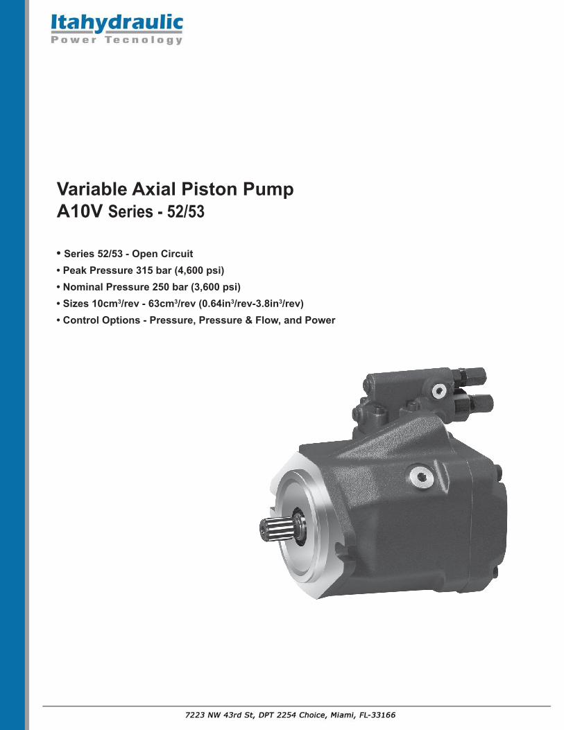
• Series 52/53 - Open Circuit• Peak Pressure 315 bar (4,600 psi)• Nominal Pressure 250 bar (3,600 psi)• Sizes 10cm3/rev - 63cm3/rev (0.64in3/rev-3.8in3/rev)• Control Options - Pressure, Pressure & Flow, and Power
Variable Axial Piston Pump A10V Series - 52/53
Series 52
w w w. F l u i D y n e F P. c o mE m a i l : sales @ F l u i D y n e F P. c o m
Axial piston pump A10V in swashplate design is used for hydrostatic transmission in open loop circuits. Flow is proportional to drive speed and displacement. By adjusting the position of the swashplate it is possible to smoothly vary the flow.
A10V - 52/53 Valveplate
Endcover
Control valveDFRPistonVariable
piston
Cylinderblock
Swashplate
Housing
Shaft
- Flange/Threaded connections SAE-UNC or metric - 2 to 3 drain ports - High permissible speeds - Good suction characteristics - Low noise level - High power/weight ratio - Long service life - Short control times - Axial and radial loading of drive shaft possible - Wide range of controls - Through drive option for multi-circuit system
Features:Variable Displacement Pump A10V, Series 52/53
Technical Data:1. Absolute Pressure at Port S (A) Psabs min.....................11 psi (0.8 bar) Psabs max....................75 psi (5 bar)
2. Output Operating Pressure Range Pressure at port B Nominal pressure PN..........3600 psi (250 bar) Peak pressure Pmax........4600 psi (315 bar) Minimum pressure Pmin........ 145 psi (10 bar)
3. Case Drain Pressure Maximum pressure of leakage fluid (at ports L, L1 and L2) 7 psi (0.5 bar) higher than input pressure at port S, but not higher than 30 psi (2 bar) absolute.
4. Direction of Flow (S to B)
5. Table of Values (theoretical values, without considering mh and v : values rounded)
Weight (without fluid) M kg (lbs) 8 (17) 18(40) 22 (48.5) 22 (48.5)
Note: Values shown are valid for an absolute pressure of 1 bar at suction port.
Variable Displacement Pump A10V, Series 52/53
Technical Data:
6. Determination of Size
Flow qv = [gpm] q v = [L/min]
Torque T = [lb-ft] T = [Nm]
Power P = [HP] P = [kW]
Vg • n • ηv
1000
V g • ∆ p
20 • π • ηmh
qv • ∆ p
Vg = Displacement per revolution in in3 (cm 3)
∆ p = Di�erential pressure in psi (bar)
n = Speed in rpm (min –1 )
ηv = Volumetric e�ciency
ηmh = Mechanical-hydraulic e�ciency
ηt = Total e�ciency
600 • ηt
Vg • n • ηv
231
24 • π • ηmh
q v • ∆ p
1714 • ηt
V g • ∆ p
(
((
)))
Fluid MR20S (Q/TCNK12-2001) ISO 32 ISO 46 ISO 68
Spee
d n/
n0
max
[rpm
]
Inle
t pre
ssur
e p
abs [
psi (
bar)
]
Displacement V g/Vg max [in3 (cm 3)]
1.00.90.80.7
1.2
1.1
1.0
0.9
23
20
17.5
14.5
13
11.5
(1.6)
(1.4)
(1.2)
(1.0)
(0.9)
(0.8)
Speed vs. Inlet PressureIf the flow is reduced or if the inlet pressure is increased the speed may be increased according to the diagram.
Variable Displacement Pump A10V, Series 52/53
Operating Viscosity Range
Vopt = 16 mm2 /s~36 mm2 /s (80 to 170 SUS)
For optimum efficiency and service life we recommend that the operating viscosity (at operating temperature) be selected in the range:
Vopt = optimum operating viscosity 16mm2 /s~36 mm2 /s referred to tank temperature (open loop circuit). Limits of Viscosity Range
(The following values are valid for extreme operating conditions) Vmin = 10 mm2/s for short periods at max. leakage oil temperature of 800C (1760F) Vmax = 1000 mm2/s
Temperature Range
tmin = -200C (-40F) ; tmax = +800C (1760F)
Filtration
Technical Data:
Installation Notes
The pump housing must be filled with fluid during commissioning and remain full when operating. The concentricity between engine transmission shaft and pump shaft must less than 0.05mm.
Visc
osity
Temperature tFluid Temperature Range
-40° -4° 32° 68° 104° 140° 176° 212° °F
-40° -20° 0° 20° 40° 60° 80° 100° °C
-40° -25° 10° 0° 10° 30° °C50° 70° 90° 115°
-40° -13° 14° 32° 50° 86° °F122° 158° 194° 240°
160074001000460060030004002000
2001000
1005006030040200
20100
06 01
mm2/sSUS24 5
80
74001600
63 071
8016
5 24SUSmm2/s
t max = 240°F (115°C)t min = -40°F (-40°C)
VG 22VG 32VG 46VG 68VG 100
In order to ensure reliable operation of the axial piston unit, the operating fluid must be maintained to a cleanliness class of at least: 16/19 to IS04406. This may be achieved with filter elements, cleanliness class of 10µm.
Variable Displacement Pump A10V, Series 52/53
Technical Data:
Drive Power and Flow
Operating material:Hydraulic fluid ISO VG 46 DIN 51519, t = 50 °C
Technical data
Operating material: ISO VG 46 DIN 51519, t = 50 °C
n = 1500 rpm n = 3600 rpm
q V
pqV min
pqV max
(250)(200)(150)(100)(50)
1000 2000Operating presure p
3000 3625
(bar)
psi
(5)
(10 )
(15 ) 20
3025
15105
(20)
00
(5)
(15 )
(25)
(35)10
7.5
5
2.5
(L/min) (kW) HPgpm
Flow
qV
Driv
e po
wer
P q
V
n = 1500 rpm
n = 2600 rpm
qv
Pqv max
Pqv min
(250)(200)(150)(100)(50)
0Operating pressure p
3625300020001000
(bar)
psi
(20)
(40)
(60)
(80)20
15
0
gpm (L/min)
5
10(10)
(20)
(30)
(40)
Driv
e po
wer
Pqv
20
40
60
0
)Wk( PH
(100)25
(120)30
(50)
(60) 80
Flow
qv
n = 1500 rpm n = 2600 rpm
qv
Pqv max
Pqv min
(250)(200)(150)(100)(50)
0Operating pressure p
3625300020001000
(bar)
psi
(20)
(40)
(60)
(80)20
15
0
5
10
(100)25
(120)30
Flow
qv
(10)
(20)
(30)
(40)
Driv
e po
wer
Pqv
20
40
60
0
)Wk( PH
(50)
(60) 80
gpm (L/min)
(140)35
(160)40
(70)
(80)100
Size 10
Size 45
Size 60/63
Variable Displacement Pump A10V, Series 52/53
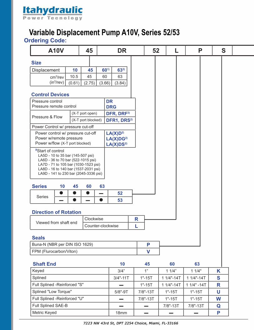
A10V 45 DR 52 L P S C 62 N00 S097
Displacement 10 45 601) 632)
cm3/rev(in3/rev)
10.5 45 60 63(0.61) (2.75) (3.66) (3.84)
Size
Control DevicesPressure controlPressure remote control
DRDRG
Pressure & Flow(X-T port open) DFR, DRF2)
(X-T port blocked) DFR1, DRS2)
Power Control w/ pressure cut-offPower control w/ pressure cut-offPower w/remote pressurePower w/flow (X-T port blocked)
LA(X)D2)
LA(X)DG2)
LA(X)DS2)
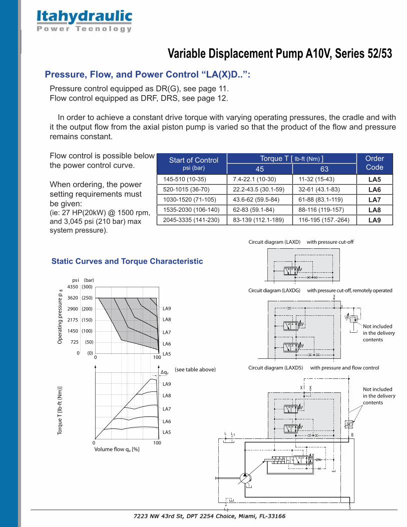
XStart of controlLA5D - 10 to 35 bar (145-507 psi)LA6D - 36 to 70 bar (522-1015 psi)LA7D - 71 to 105 bar (1030-1523 psi)LA8D - 16 to 140 bar (1537-2031 psi)LA9D - 141 to 230 bar (2045-3336 psi)
Series 10 45 60 63
Series● ● ● ▬ 52▬ ● ▬ ● 53
Direction of Rotation
Viewed from shaft endClockwise RCounter-clockwise L
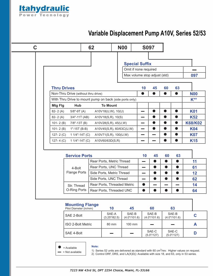
Note:1) Series 52 units are delivered as standard with 60 cm3/rev. Higher values on request.2) Control DRF, DRS, and LA(X)D(): Available with size 18, and 63, only in 53 series.
Variable Displacement Pump A10V, Series 52/53
Pressure Control “DR”:
The pressure control serves to maintain a constant pressure in the hydraulic system, within the control range of the pump. The pump therefore supplies only the amount of hydraulic fluid required by the actuators. Pressure may be smoothly set at the pilot valve.
B
S
L 1L
2L (avail. 53-design only)
Static characteristic
(at n1 = 1500 rpm; t�uid = 120 °F (50 °C))
(20)
(250)psi (bar)
3600
290
Ope
ratin
g pr
essu
re p
B
Hys
tere
sis
/ pre
ssur
e ris
e �
p max
Sett
ing
rang
e1)
Flow qv [gal (l/min)]
B Pressure portS Suction portL, L1,2 Case drain ports (L1,2 sealed)
Ports
Control DataHysteresis and repetitive accuracy p..................max. 3 bar (44 psi)
Pilot oil consumption...............max. approx. 3 L/min (0.8 gpm)
Static Characteristic
Variable Displacement Pump A10V, Series 52/53
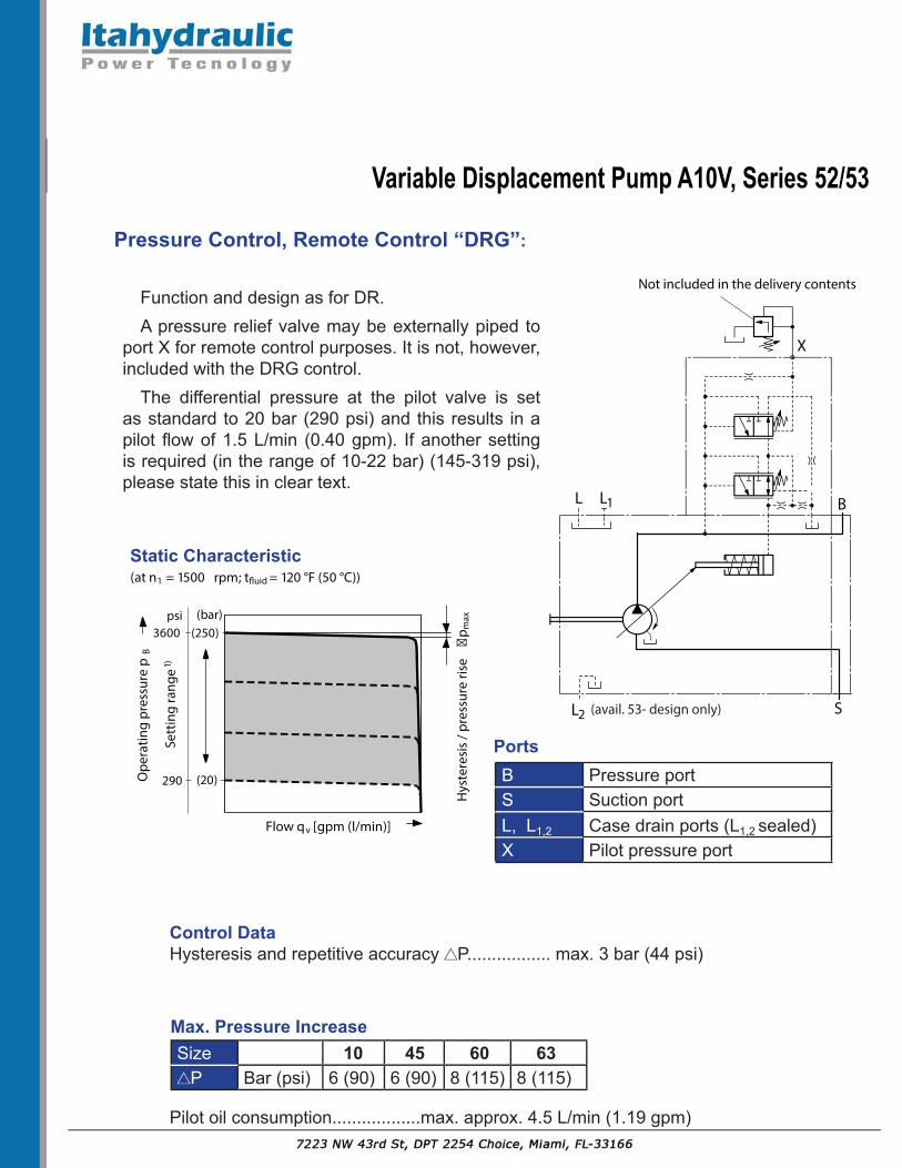
Pressure Control, Remote Control “DRG”:
Function and design as for DR.A pressure relief valve may be externally piped to
port X for remote control purposes. It is not, however, included with the DRG control.
The differential pressure at the pilot valve is set as standard to 20 bar (290 psi) and this results in a pilot flow of 1.5 L/min (0.40 gpm). If another setting is required (in the range of 10-22 bar) (145-319 psi), please state this in clear text.
B
X
L
S
1L
2L
Not included in the delivery contents
(avail. 53- design only)
Static characteristic
(at n1 = 1500 rpm; t�uid = 120 °F (50 °C))
(20)
(250)psi (bar)
3600
290
Flow qv [gpm (l/min)]
Ope
ratin
g pr
essu
re p
B
Hys
tere
sis
/ pre
ssur
e ris
e �
p max
Sett
ing
rang
e1)
B Pressure port S Suction port L, L1,2 Case drain ports (L1,2 sealed) X Pilot pressure port
Ports
Control DataHysteresis and repetitive accuracy P................. max. 3 bar (44 psi)
Max. Pressure Increase Size 10 45 60 63
P Bar (psi) 6 (90) 6 (90) 8 (115) 8 (115)
Pilot oil consumption..................max. approx. 4.5 L/min (1.19 gpm)
Static Characteristic
Variable Displacement Pump A10V, Series 52/53
Pressure/Flow Control, Load Sensing:“DFR/DRF” X-T port open, “DFR1/DRS” X-T port blocked
In addition to the pressure control function, the pump flow may be varied by means of a differential pressure at the actuator (e.g. an orifice).
In model DFR1/DRS the X orifice is plugged. 1LL B
S
X
2L
Not
incl
uded
in th
e de
liver
y co
nten
ts
Plugged in DRS (DFR1) valve
(avail. -53 design only)
B Pressure portS Suction portL, L1, 2 Case drain ports (L1,2 sealed)X Pilot pressure port
Static characteristic
Flow control at n1 = 1500 rpm; t�uid = 120 °F (50 °C))
(20)
(250)psi (bar)
3625
290Ope
ratin
g pr
essu
re p
B
Sett
ing
rang
e1)
Flow qv [gpm (l/min)]
Hys
tere
sis
/ pre
ssur
e ris
e �
p max
Ports
Flow control/differential pressure p: Adjustable between 14 and 22 bar (200-320 psi)
(higher values on request). Standard setting: 21 bar (300 psi). If a different setting is required, please state in clear text.
When port X is unloaded to tank, a zero stroke pressure of p = 21 bar (300 psi) (“stand by”) results.
Static characteristic at variable speed
Speed n [rpm]
Flow
qv [
l/min
]
Hys
tere
sis
/ pre
ssur
e ris
e �
p max
Control Data For pressure control technical data see DR Pressure control. Max. flow deviation (hysteresis and increase) measured at drive speed n = 1450 rpm
Pressure control equipped as DR(G), see page 11.Flow control equipped as DRF, DRS, see page 12.
In order to achieve a constant drive torque with varying operating pressures, the cradle and with it the output flow from the axial piston pump is varied so that the product of the flow and pressure remains constant.
Flow control is possible below the power control curve.
When ordering, the power setting requirements must be given: (ie: 27 HP(20kW) @ 1500 rpm, and 3,045 psi (210 bar) max system pressure).
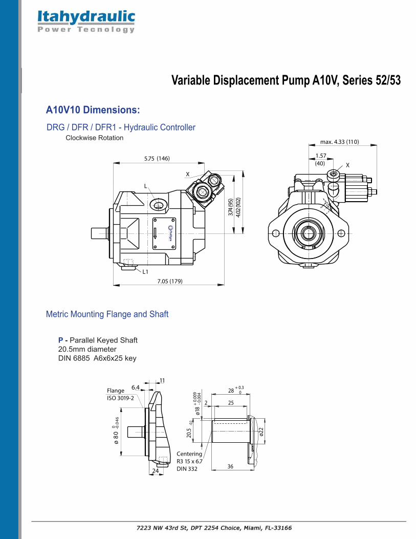
DR - Hydraulic Pressure ControllerA10V45 Dimensions:
Clockwise Rotation 2), -52 Series
1) Primary dimensions for pump apply for series -52 and -53 as seen above.2) Location of service ports S and B are turned 180˚ for counter-clockwise rotation.
5.18
(131
.5)
45°
3.07 (78)
6.77 (172 )5.75 (146)
0.56
(14.
3)3.
03 (7
7)2.
70 (6
8.5)
( Ø10
1.6
)D
IA4.
000
max. 8.68 (220.5)
1.18 (3 0)
7.44 (18 9)
L
L1
0.25 (6.3)0.47 (12 )
3.90 (99 )0.37 (9.5)
X
Flange ISO 3019-1
1.50(3 8)
1.50(3 8)
BS
89.0 AI
D) 52ø(
2.06
(52.
4)
30 °
05.1 AI
D83ø
1.41(35.7)
1.03 (26.2)
2.75
(69.
9)
30 °
View X
Port plate 61/11
Port plate 64
1.50(38)
1.50(38)
S B
Variable Displacement Pump A10V, Series 52/53
DR - Hydraulic Pressure ControllerA10V45 Dimensions:
Clockwise Rotation 2), -52 Series
Port plate 62/12
8.31 (2 11)7.01 (178 )
L
L1
3.90 (9 9)5.93 (150.5)
1.18 (3 0)0.25 (6.3)0.47 (12)0.37 (9.5)
1.41 (35.7)
max. 8.68 (220.5)
DIA
1.5
0 (ø
38)
69.9
S
Y
Flange ISO 3019-1
( Ø10
1.6
)
DIA
4.00
0
BS Z
3.54 (9 0) 3.54 (9 0)
View Y
2.06
(52.
4)D
IA 0
.98
(Ø25
)
B
1.03(26.2)
Detail Z
Variable Displacement Pump A10V, Series 52/53
LA( )D(S/G) 1) 4) - Hydraulic ControllerPressure, Flow and Power ControlClockwise Rotation 2), -53 Series
DRG / DFR / DFR1 1) 3) - Hydraulic ControllerRemote Pressure Control/ Pressure and FlowClockwise Rotation 2), -52 Series
L
L1
5.93 (150.5)
5.18
(131
.5)
max. 8.68 (220.5)2.68 (68)
X
S4.
53 (1
15)
1) Primary dimensions for pump apply for series -52 and -53 as seen on page 18.2) Location of service ports S and B are turned 180˚ for counter-clockwise rotation.3) DFR1; Pressure and flow control with blocked bleed down orifice4) Only for -53 series.
DIN 131.0"; M10 x 1.5; 17 deep1-1/2"; M12 x 1.75; 20 deep 48 lb-ft (66 Nm)
BS
Outlet Port; ThreadedInlet Port; Threaded 64 ISO 11926 1-5/16"-12UN-2B; 0.79 (20) deep
1-7/8-12UN-2B; 0.79 (20) deep 243 lb-ft (330 Nm)
L, L1, L2
4) Case Drain Ports (L1 plugged) All ISO 11926 3/4-16UNF-2B 116 lb-ft (160 Nm)
X Pilot Pressure Port All ISO 11926 7/16-20UNF-2B; 0.45 (11.5) deep 29 lb-ft (40 Nm)
1) Primary dimensions for pump apply for series -52 and -53 as seen above.2) Location of service ports S and B are turned 180˚ for counter-clockwise rotation.3) Metric fixing thread is a deviation from standard.4) Only for -53 series.
1) Primary dimensions for pump apply for series -52 and -53 as seen above.2) Location of service ports S and B are turned 180˚ for counter-clockwise rotation.
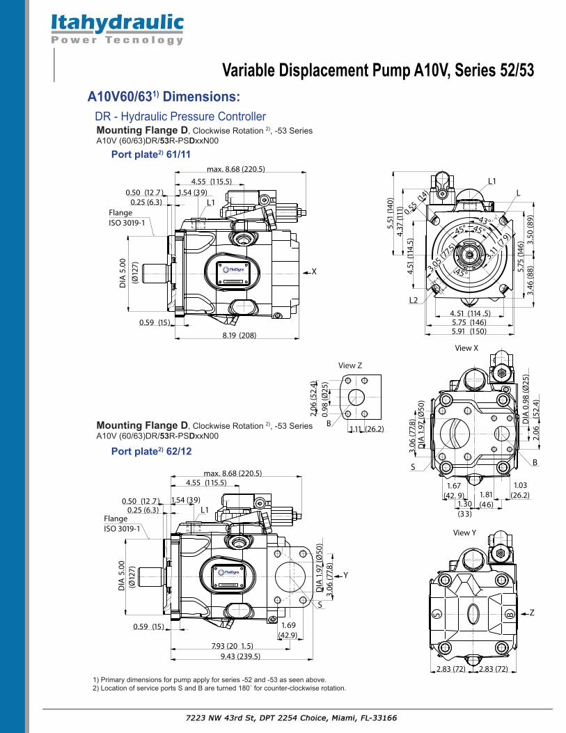
Mounting Flange D 1), Clockwise Rotation 2), -52 SeriesA10V (60/63)DR/52R-PSDxxN00
Port plate2) 62/12max. 8.68 (220.5)
0.50(12 .7)
Y
4.61 (117 )
1.57(40)
1.67(42.9)
S
7.93 (201.5)9.43 (239.5)
DIA
1.9
7 (Ø
50)
3.06
(77.8
)
0.59 (15 )
X
(Ø10
1.6
)D
IA4.
00
Flange ISO 3019-1
Z
2.83 (72) 2.83 (72)
BS
View Y
B
2.06
(52.
4)
1.11 (26.2)
0.98
(Ø25
)
View Z
3.07
(78)
114.
5
5.83
(148
)5.
41 (1
37.4
)
3.43
(87)
45°
3.09 (78.5)
5.75 (146)4.51 (114 .5)
14.3
L
L1
max. 8.68 (220.5)
0.50(12 .7)
Y
4.61 (117 )
1.57(40)
1.67(42.9)
S
7.93 (201.5)9.43 (239.5)
DIA
1.9
7 (Ø
50)
3.06
(77.8
)
0.59 (15 )
X
(Ø12
7 )
DIA
5.00
Flange ISO 3019-1 2.83 (72) 2.83 (72)
ZBSView Y
A10V60/63- D Mounting Flange
1) Primary dimensions for pump apply for series -52 and -53 as seen above.2) Location of service ports S and B are turned 180˚ for counter-clockwise rotation.
1) Primary dimensions for pump apply for series -52 and -53 as seen above.2) Location of service ports S and B are turned 180˚ for counter-clockwise rotation.
1) Primary dimensions for pump apply for series -52 and -53 as seen above and on previous pages.2) Location of service ports S and B are turned 180˚ for counter-clockwise rotation.3) DFR1/DRS; Pressure and flow control with blocked bleed down orifice.4) Only for -53 series.
DIN 131.0"; M10 x 1.5; 17 deep2.0"; M12 x 1.75; 20 deep 48 lb-ft (66 Nm)
BS
Outlet Port; ThreadedInlet Port; Threaded 64 ISO 11926 1-5/16"-12UN-2B; 0.79 (20) deep
2-1/2"-12UN-2B; 0.87 (22) deep 243 lb-ft (330 Nm)
L, L1, L2
4) Case Drain Ports (L1 plugged) All ISO 11926 7/8-14UNF-2B; 0.51 (13) deep 116 lb-ft (160 Nm)
X Pilot Pressure Port All ISO 11926 7/16-20UNF-2B; 0.45 (11.5) deep 29 lb-ft (40 Nm)
1) Primary dimensions for pump apply for series -52 and -53 as seen above and on previous pages.2) Location of service ports S and B are turned 180˚ for counter-clockwise rotation.3) Metric fixing thread is a deviation from standard.4) ANSI B92.1a, 30° pressure angle, flat root, side fit, tolerance class 5.5) Splines according to ANSI B92.1a, run out of spline is a deviation from standard.
Ports
A10V60/63 Dimensions:Drive Shafts and Port Dimensions
Q - Full Splined Shaft7/8" major dia.13T 16/32 DP 4)5)
Axial piston unit A10V0 can be supplied with a through drive, as shown in the ordering code on pages 8 and 9. The type of through drive is determined by codes (K01-K15). If the combination pump is not mounted in the factory, the simple type code is sufficient. Order the coupling kit separately. Included in the kit are: Coupling sleeve, seals and bolts.
Combination Pumps: By mounting combination pumps circuits independent of each other are available for use. 1. If the combination pump consists of two A10V pumps and if these are to be delivered ready assembled, then the two types codes are to be combined with a “+”. Ordering Example: A10V45DR/52R-PSC62K04 + A10V45DFR/52R-PSC62N00
2. If a gear pump or radial piston pump is to be mounted in the factory as a second pump. It contains a list of the various pump combinations together with the type code of the first pump.
K01 Flange SAE 82-2 (SAE A, 2-hole) for mounting of external gear pump G2 or an A10V10, A10V18 - U Shaft. Order K01 coupling separately to mate to a 5/8” dia. 9T-tooth shaft.
(Dimensions mm)
Variable Displacement Pump A10V, Series 52/53
Dimensions of Through Drives (continued):
A 5
A B
45°
4.1910 6.5
A1
A 4A 3
0.39(10 )
(ø82
.55
)
3.25
203.
2508
DIA
+0.
050
+0.
020
A 2
Omitted for NG28
Omitted for NG28to mounting �ange
Sizes A1 mm (in.) A2 mm (in.) A3 mm (in.) A445 234 (9.21”) 39.4 (1.55”) 53 (2.09”) 6-M10-1.5, (16 deep)
K68 Flange SAE 101-2 (SAE B, 2 hole) for mounting an A10V45 - U shaft or an A10V28 - S shaft. Order K68 coupling separately to mate to a 7/8” dia. 13T-tooth shaft.
A5
A B
45°
5.75(146)
A 1
A4
A3
0.39(10 )
(ø10
1.6
)
4.00
204.
0008
DIA
+0.
050
+0.
020
A2
Omitted for NG28, 45
Omitted for NG28, 45to mounting �ange
Sizes A1 mm (in.) A2 mm (in.) A3 mm (in.) A545 234 (9.21”) 42.4 (1.67”) 18 (0.71”) 2-M12-1.75, (18 deep)
K52 Flange SAE 82-2 (SAE A, 2-hole) for mounting of an A10V10, A10V18 - S shaft or an A10V28 - U shaft. Order K01 coupling separately to mate to a 3/4” dia. 11T-tooth shaft.
Variable Displacement Pump A10V, Series 52/53
K15 Flange SAE 127-4 (SAE C, 4 hole) for mounting an A10V60/63 “D” pilot pump with an S-shaft. Order K15 coupling kit separately, for mating with a 1-1/4” dia.14T-tooth spline shaft.
(ø12
7
)
5.00
205.
0008
DIA
+0.0
50+0
.020
B
A
4.51
(114
.5)
4.51 (114.5) A5 0.53(13.4)A1
A3
A4
to mounting �ange
Sizes A1 mm (in.) A3 mm (in.) A4 mm (in.) A560/63 255 (10.04”) 8 (0.31”) 59 (2.32”) 2-M12-1.75, (16 deep)
Sizes A1 mm (in.) A2 mm (in.) A3 mm (in.) A545 229 (9.02”) 48 (1.88”) 19 (0.74”) 2-M12-1.75, (18 deep)
K04 Flange SAE 101-2 (SAE B, 2 hole) for mounting an A10V45 - shaft S or an A10V60/63 - U Shaft. Order K04 coupling separately to mate to a 1” dia. 15T-tooth shaft.
A5
A B
45°5.75(146)
A 1
A4A3
0.39(10 )
(ø10
1.6
)
4.00
204.
0008
DIA
+0.0
50+0
.020
A2
Omitted for NG45
Omitted for NG45
to mounting �ange
Dimensions of Through Drives (continued):
Variable Displacement Pump A10V, Series 52/53
Installation Instructions:General
The axial piston unit must be filled with hydraulic fluid and air bled during commissioning and operation. This must also be observed following a longer standstill as the axial piston unit empty via the hydraulic lines.
Especially with the installation position “pump shaft upwards” or “pump shaft downwards”, attention must be paid to completely filling and air bleeding the pump since there is a risk of dry running.
The case drain fluid in the case interior must be directed to the reservoir via the highest case drain port ( L, L1, L2 ).
For combinations of multiple units, make sure that the respective case pressure in each unit is not exceeded. In the event of the pressure differences at the drain ports of the units, the shared drain line must be changed so that the minimum permissible case pressure of all connected units is not exceeded in any situation. If this is not possible, separate drain lines must be laid.
To achieve favorable noise values, decouple all connecting lines using elastic elements and avoid above reservoir installation.
In all operating conditions, the suction line and the case drain line must flow into the reservoir below the minimum fluid level. The permissible suction height hѕ max = 31.50 in (800 mm). The minimum suction pressure at port S must also not fall below 12 psi (0.8 bar) absolute during operation.
Installation Position:See the following examples 1 thru 12 for proper
plumbing of hydraulic lines for various pump installations. Installation positions 1 and 3 are the recommended conditions most favorable for a long extended life of the pump.
Below-Reservoir Installation (Standard)Below-reservoir installation means the axial
piston unit is installed outside of the reservoir below the minimum fluid level.
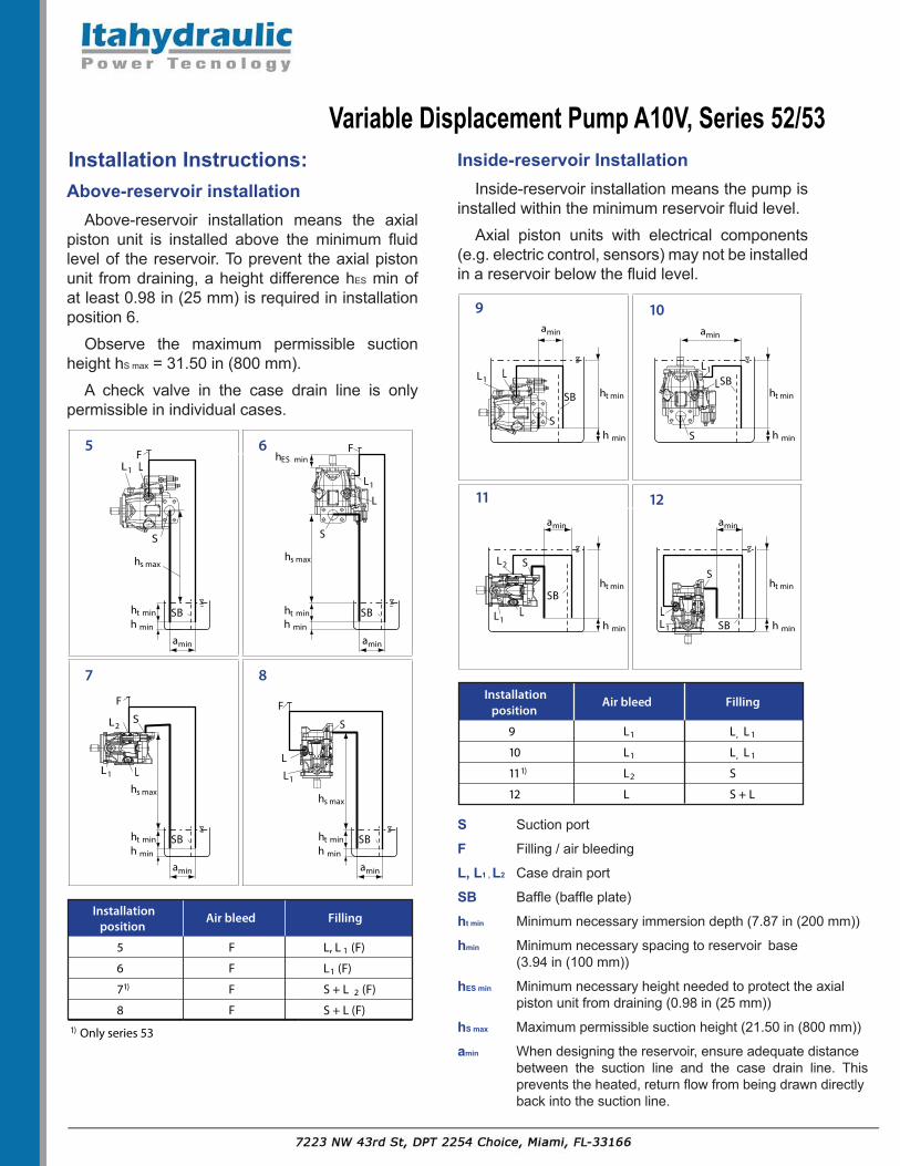
Above-reservoir installation means the axial piston unit is installed above the minimum fluid level of the reservoir. To prevent the axial piston unit from draining, a height difference hES min of at least 0.98 in (25 mm) is required in installation position 6.
Observe the maximum permissible suction height hS max = 31.50 in (800 mm).
A check valve in the case drain line is only permissible in individual cases.
Inside-reservoir InstallationInside-reservoir installation means the pump is
installed within the minimum reservoir fluid level.Axial piston units with electrical components
(e.g. electric control, sensors) may not be installed in a reservoir below the fluid level.
Installation instructions cont.:
9 10
11 12
Installation position
Air bleed Filling
9 L1 L, L 1
10 L1 L, L 1
111) L2 S
12 L S + L
S Suction port
F Filling / air bleeding
L, L 1 Case drain port
SB
ht min
hmin
hES min
hS max
amin
Above-reservoir installation
5 6
7 8
Installation position
Air bleed Filling
5 F L, L 1 (F)
6 F L1 (F)
71) F S + L 2 (F)
8 F S + L (F)
Only series 531)
X
X
LL1
S
F
hs max
ht min
amin
SB
S
F
L
L1
L
L2
L1
S
F
S
F
L
L1
h min
hs maxhs max
hs max
hES min
ht min
amin
SBh min
ht min
amin
SBh min
ht min
amin
SBh min
X
X
LL1
S
ht min
h min
ht min
h min
ht min
h min
ht min
h min
amin
amin amin
amin
SB
L
L2
L1
S
SB
LL1
S
SB
LL1
S
SB
Inside-reservoir InstallationAbove-reservoir installation means the axial piston unit isinstalled above the minimum fluid level of the reservoir.To prevent the axial piston unit from draining, a height difference hES min of at least 0.98 in (25 mm) is required in installation position 6.Observe the maximum permissible suction heighthS max = 31.50 in (800 mm).A check valve in the case drain line is only permissible in individual cases.
Minimum necessary spacing to reservoir base(3.94 in (100 mm))Minimum necessary height needed to protect theaxial piston unit from draining (0.98 in (25 mm)).
Maximum permissible suction height (21.50 in(800 mm))
When designing the reservoir, ensure adequatedistance between the suction line and the case
from being drawn directly back into the suctionline.
Inside-reservoir installation means the pump is installed withinthe minimum reservoir fluid level.Axial piston units with electrical components (e.g. electriccontrol, sensors) may not be installed in a reservoir below thefluid level.
Installation instructions cont.:
9 10
11 12
Installation position
Air bleed Filling
9 L1 L, L 1
10 L1 L, L 1
111) L2 S
12 L S + L
S Suction port
F Filling / air bleeding
L, L 1 Case drain port
SB
ht min
hmin
hES min
hS max
amin
Above-reservoir installation
5 6
7 8
Installation position
Air bleed Filling
5 F L, L 1 (F)
6 F L1 (F)
71) F S + L 2 (F)
8 F S + L (F)
Only series 531)
X
X
LL1
S
F
hs max
ht min
amin
SB
S
F
L
L1
L
L2
L1
S
F
S
F
L
L1
h min
hs maxhs max
hs max
hES min
ht min
amin
SBh min
ht min
amin
SBh min
ht min
amin
SBh min
X
X
LL1
S
ht min
h min
ht min
h min
ht min
h min
ht min
h min
amin
amin amin
amin
SB
L
L2
L1
S
SB
LL1
S
SB
LL1
S
SB
Inside-reservoir InstallationAbove-reservoir installation means the axial piston unit isinstalled above the minimum fluid level of the reservoir.To prevent the axial piston unit from draining, a height difference hES min of at least 0.98 in (25 mm) is required in installation position 6.Observe the maximum permissible suction heighthS max = 31.50 in (800 mm).A check valve in the case drain line is only permissible in individual cases.
Minimum necessary spacing to reservoir base(3.94 in (100 mm))Minimum necessary height needed to protect theaxial piston unit from draining (0.98 in (25 mm)).
Maximum permissible suction height (21.50 in(800 mm))
When designing the reservoir, ensure adequatedistance between the suction line and the case
Inside-reservoir installation means the pump is installed withinthe minimum reservoir fluid level.Axial piston units with electrical components (e.g. electriccontrol, sensors) may not be installed in a reservoir below thefluid level.
S Suction port
F Filling / air bleeding
L, L1 , L2 Case drain port
SB Baffle (baffle plate)
ht min Minimum necessary immersion depth (7.87 in (200 mm))
hmin Minimum necessary spacing to reservoir base (3.94 in (100 mm))
hES min Minimum necessary height needed to protect the axial piston unit from draining (0.98 in (25 mm))
hS max Maximum permissible suction height (21.50 in (800 mm))
amin When designing the reservoir, ensure adequate distance between the suction line and the case drain line. This prevents the heated, return flow from being drawn directly back into the suction line.