1. Chapter 10, Harris
CRYSTAL SETS TO SIDEBAND
© Frank W. Harris 2010, REV 12
Chapter 10
Variable Frequency Oscillators (VFOs) Sooner or later you'll become frustrated with being stuck on a few crystal-controlled
frequencies. You would like to have a frequency-tuning knob that covers the entire band and not
just a few kilohertz. This sounds simple, but isn’t. It’s difficult because, without the stability of
a crystal, an ordinary RF oscillator will drift hundreds of hertz while you’re sending. The fellow
you’re talking to probably has a modern transceiver with a narrow, stable passband. From his
perspective your signal quickly drifts out of his passband. His digital readout may be calibrated
to tenths of a Hertz and he will take great delight in telling you about YOUR PROBLEM.
Drift is a big deal today
In the old days, like 1950, receiver passbands were usually huge, like 10 or 20 kilohertz.
So you could drift quite a distance before your contact even noticed, let alone could no longer
hear you. Besides, everyone drifted a little back then, so it wasn’t worth mentioning. In the
really old days, like 1930, the signals drifted so much, that hams often tuned their receivers with
one hand while they copied down the Morse code with the other.
A 5 MHz VFO tuned by a mechanical variable capacitor
A stable variable frequency
oscillator can replace a crystal oscillator.
This chapter summarizes what I learned in
my odyssey through six VFO prototypes.
My early VFOs drifted hundreds of Hz and
I got loads of complaints. After I added
temperature compensation, I got the
instability down to 20 Hz drift per minute.
Some stations notice 20 Hz drift and a few
even told me about it. Eventually I built a
super-regulated power supply for the VFO
and got the drift down to about 5 Hz. I
suggest you avoid embarrassment and
work directly toward 5 Hz. According to
the ARRL handbook, +/- 5 Hz is about as
stable as you can achieve without phase
lock loop technology.
2. Chapter 10, Harris
I was recently talking to a brand new local ham on 40 meters CW. We were chatting at a
leisurely 5 words per minute. He, of course, was using a wondrous modern transceiver. It took
us an hour to communicate very little information. Finally he tired of the strain and called me on
the phone. "By the way," he said, "were you aware that you drifted over 50 Hz during our
QSO?" He thought he was informing me of a grievous defect in my rig. Less than 1 Hz per
minute? I was delighted that the drift was so low.
The test equipment needed to build a VFO are a precision multimeter for measuring
voltage down to millivolts and a frequency standard. A super-accurate, modern receiver is OK,
but a frequency counter is better for this application. The hardest part about building a stable
VFO is following all the detailed instructions on how to do it. If you’re like me, you’ll have
trouble believing that all that trivia is really necessary. Yes, you can cut a few corners, but the
more compromises you make, the more your VFO will drift.
Low frequency VFOs drift less than high frequency VFOs
It’s practical to build a VFO that operates directly on 160 meters (1.8 to 2.0 MHz) or on
80 meters (3.5 to 4.0 MHz). This makes transmitter design simple. For these bands you just
amplify the VFO signal directly. For example, if you had a crystal-controlled QRP designed for
80 meters, an 80 meter VFO could be plugged directly into the crystal socket. You might want to
attenuate the signal somewhat before directly substituting a crystal, but the VFO can replace the
crystal and allow you to tune all over the band. If you can build a really first rate VFO for 40
meters, that band would also be practical. Unfortunately, for a given level of sophistication and
precision, frequency drift is directly proportional to frequency. You will probably find that
somewhere above 5 MHz, there is too much instability to keep the drift under 5 Hz per minute.
In order to build a low drift VFO for 40 meters or above, a low frequency VFO can be
"converted" up to the desired high frequency. Conversion means adding the VFO to a high
frequency crystal oscillator signal and then extracting the sum frequency with a filter. Frequency
conversion is covered in chapter 11.
Considering the size of most HF ham bands, a VFO needs a tuning range of at least 0.5
MHz. The higher the basic frequency of the VFO, the wider the tuning range you can achieve.
ARRL handbook VFO projects have various frequencies ranging from 1.75 to 9 MHz. My CW
transmitter VFO ranges from 3.5 to 4.0 MHz. My receiver and SSB-transmitter VFOs tune from
5.0 to 5.5 MHz. In retrospect, if I were starting over, I would have built the 5 MHz VFO first,
since that frequency turns out to be more versatile. The disadvantage of a 5 MHz VFO is that it
can’t be used on any hamband directly and every hamband needs a frequency converter circuit.
(Yes, a 5 MHz VFO can reach 60 meters. But CW isn't permitted on 60 and generating SSB on
the same frequency on which you're transmitting requires a phase shift technique that is rarely
used today.)
JFET transistors
Junction Field Effect Transistors (JFETs) are ideal for building VFOs. Unlike bipolar
transistors, the main current from the drain to the source does not pass through any PN junctions.
PN junctions change their characteristics with temperature. Therefore, VFOs made from bipolar
transistors tend to drift more than JFETs. JFETs work on the same principle as a MOSFET, but
the control gate is a P-N junction diode rather than a capacitor. JFETs were explained and used
in the VFO oscillator in the direct conversion receiver in chapter 7.
3. Chapter 10, Harris
THE VFO CIRCUIT
The basic oscillator
In principle the VFO is almost the same as a quartz crystal oscillator. The crystal is
electrically equivalent to an LC resonant circuit. Therefore, to tune a VFO we use either a
variable capacitor or a variable inductor to change the resonant frequency. So far as I know,
suitable variable inductors can’t be bought or built in a home workshop. That means that the
tuning element will have to be a variable capacitor, much like the one you used to adjust the
crystal frequency in your QRP.
The circuit above is essentially what you will find in your ARRL handbook. It uses a
JFET transistor. The oscillator is a Colpitts and can be recognized by the capacitive divider
feedback, C3 and C4. Whenever the source voltage goes up, some of this change is coupled to
the gate through C3. This turns the JFET more ON. That is, the feedback is positive which
sustains the oscillation. The basic LC resonant circuit that determines the frequency is C1 and
L1. C2 is a trimmer capacitor to help adjust the desired tuning range.
So what are the values of C1, L1, C2, etc.? The answer isn’t simple. We start with a
quality variable capacitor for C1 as described below. For various reasons, C1 will probably be
about 30 pF. Starting with this capacitor and the need for a 0.5 MHz tuning range, the other
values must be determined by trial and error. The values are extremely hard to calculate because
C3, C4 and even the 1N914 diode are part of the capacitance. Don’t try too hard to get the values
right until you have studied this entire chapter and formulated a plan for your VFO. As you will
see later, C2, C3, and C4 are part of the temperature compensation strategy and will need to be
determined by those considerations first. When you have decided what to do about C3 and C4,
then you can work on L1 and C2.
The 470 µHenry choke in the source circuit serves as the load “resistor.” That is, the
oscillator sinewave output is locked in between the operating voltage, +5 volts, and ground.
Since the sinewave voltage appears across the transistor, the remainder, 5 volts minus the
sinewave, must appear across a load of some sort. This choke could be functionally replaced
with a resistor, except that a resistor dissipates energy and gets hot. The last thing you need in
your VFO is another source of heat. The choke inductance is high enough so that the current
through it changes very little during one RF cycle and its effect on the frequency of oscillation is
4. Chapter 10, Harris
minimal and unchanging.
While we’re on the subject, you might experiment with substituting an LM336-2.5 volt
precision Zener diode for the 5 volt diode. This would of course cut the amplitude of the
oscillation in half, but it will also decrease the circuit heating to one fourth. It may not work out
for you, but anything that reduces heating, increases stability.
The 1N914 diode on the gate seems counter-productive, but it is used as a clamp to keep
the base of the JFET transistor out of the forward conduction region. That is, when the
oscillation gets too vigorous and the gate P-N junction begins to turn on at 0.6 volts, the diode
will help prevent operation in this range. The VFO as a whole is powered by 12 volts. However,
5 volts derived from a Zener diode regulator (Z) power the oscillator stage and its buffer. This is
done to dissipate as little energy as possible in the oscillator and prevent the components from
heating.
The entire VFO circuit
Here is the entire VFO circuit, excluding the temperature compensation. As you can see, the
VFO also contains a buffer stage and a final amplifier. Temperature compensation consists of
special circuits that replace either C2 or C4.
Buffer
The buffer stage separates the oscillator from the final amplifier. Otherwise there would
be a subtle connection between the load on the VFO output and the oscillator. Believe it or not,
without the buffer, if you change the load on the VFO output slightly, the frequency will change
too. The buffer is connected to the other stages by C5 and C6. These capacitors should be as
small as possible to reduce the connection between the oscillator and final amplifier.
5. Chapter 10, Harris
Final amplifier
The final amplifier raises the VFO output up to the level needed to drive the transmitter.
The stage being driven in the transmitter is usually a “mixer” which we shall discuss in the next
chapter. But, if the VFO is designed for the 80 meter ham band, then the next stage after the
VFO could be a string of class C amplifiers to increase the output power to the final level, say 5
or 50 watts. The VFO final stage will need to deliver at least two volts peak sine wave. Since
we have deliberately kept the oscillator and buffer signals tiny, the final amplifier must be a
linear or Class A amplifier to get the signal level up to 2 to 5 volts peak. The drive to this
transistor is biased with a 33K resistor so that this stage is always turned on.
Low pass filter
The drive to the transmitter should be as pure a sinewave as possible to avoid radiating
harmonics outside the hamband. A low pass filter on the output attenuates most of the harmonics
above the desired frequency range. A Chebyshev low pass filter is shown designed for a 500
ohm load. In Chapter 6 you were introduced to Chebyshev filters designed for 50 ohms.
However, here we have no need for power, just voltage. Therefore, the filter is designed for 500
ohms, which is plenty of drive current for this application. Values are given for both a 80 meter
VFO (3.5 to 4.0 MHz) or a 5 MHz VFO (5.0 to 5.5 MHz).
******************************************************************************
**
The 50 secrets of avoiding drift
Suppose you were to build the above VFO without reading the details in the following
paragraphs: When you first turn it on, you will be disappointed to find that it drifts a hundred Hz
per minute or more. The drift is caused by temperature change. The components expand and
contract with temperature and this causes small changes in the capacitance and inductance of the
components. Air wafting across the board doesn’t allow the temperature to stabilize. Drift is
prevented by preventing temperature change and by choosing components that change as little
as possible with temperature.
VFO building is an art form as arcane as Grandma’s secret pie crust recipe or the fine
points of building Cub Scout Pinewood Derby racers. As you’ll see, there must be 50 ways to
improve the drift problem. I have never built a VFO that was completely "stable" and probably
never will. But perhaps that’s because I only know the 14 secrets listed below. If you apply as
many of these as possible, you should get within the 20 Hz target - and maybe even under 5 Hz.
Secret # 1. Use Junction Field Effect Transistors (JFETs). The first secret of a stable VFO is
using a JFET instead of a bipolar transistor. As described earlier, a field effect transistor is better
because it is less sensitive to temperature. I have used 2N3823, 2N5484, and 2N4416 N-channel
JFET’s for VFO oscillators. My impression is that any small N-channel FET works well.
Secret # 2. Seal the VFO in a cast metal box. Simply protecting the VFO from air currents
makes a huge improvement. Use a heavy cast metal box so that the temperature will at least
change slowly. In contrast, a flimsy sheet-metal aluminum box will heat and cool relatively
rapidly. On the other hand, ANY box is a huge improvement over not having the circuit sealed
from air currents.
6. Chapter 10, Harris
Secret # 3. Use single-sided PC board. A double-sided PC board is constructed like a
capacitor. That is, thin metal sheets are bonded to a layer of insulator. Unfortunately, the
resulting capacitor has a significant temperature coefficient. As temperature increases, the board
material expands (thickens) and the capacitance across the board drops. If the VFO is built on
traces and islands that have changing capacitance to ground, the frequency of the oscillator will
drift slightly.
Secret #4. Mount the oscillator PC board away from the metal case on standoffs.
Following the same principle as above, do not mount the single-sided PC board flush against the
metal case. By standing the board up and away from the case, the capacitance between the traces
and the metal case can be minimized.
Secret #5. Choose and mount all components affecting the oscillator LC circuit carefully.
All the L and C components in the oscillator should be designed for minimum temperature drift.
Referring to the diagram, it is not just capacitors C1 and C2 that affect the frequency. Capacitors
in series with the 220 pF capacitor, C3, C4, and even C5 affect the frequency. To at least a tiny
degree, ALL components in contact with these capacitances can affect frequency drift. These
include the diode, the RF choke, the transistor, and the 100 K resistor.
Secret # 6. Mechanical variable capacitors should be chosen carefully. Although
appropriate mechanical variable capacitors are hard to find, they may be the best solution for you.
Pick a capacitor of about 30 to 60 PF, not larger. High capacitance variable capacitors are too
sensitive to temperature change. Smaller ones don’t tune far enough. Don’t use a capacitor
with aluminum plates – they warp too much with temperature. Brass is the best metal. Try to
find a capacitor with thick, widely-spaced plates. Paper-thin plates are compact, but warp too
easily.
An assortment of variable caps is shown below. The big brass variable cap just to the
right of center is rather big physically. However, out of this group it is the best for a VFO. The
capacitor to its right is quite stable, but its capacitance is too small. The tiny green plastic
trimmer caps in the clear plastic strip are positive temperature coefficient variables useful for
VFO temperature compensation. The round ceramic white and silver trimmer just above them is
my favorite 60 pF trimmer. I used dozens of them in the projects of this book. The small
variable cap at the bottom center has surprisingly large capacitance, 250 pF. Unfortunately it's
too unstable for a VFO.
7. Chapter 10, Harris
If the capacitor tuning is linear with degrees of rotation, the frequency it produces will be
somewhat non-linear. Ideally, the capacitor plates should have a non-linear shape that allows it
to tune an LC resonant circuit so that the frequency will be linear. Rotate the capacitor through
its range and you’ll see that a compensated capacitor has rotor plates that are not simple half
circles. As they rotate, they do not mesh with the stator plates at the same point. The non-linear
correction isn’t a big deal, but it is something to be aware of. RF Parts Co. sometimes has
adequate capacitors in stock. See www.rfparts.com.
Secret # 7. Varactors are the most stable tuning element. It’s hard to buy mechanical
variable capacitors that are mechanically and thermally stable. Collins Radio formerly tuned
their VFOs with special powdered-iron slug-tuned coils, but I’ve never seen any for sale. A
varactor capacitor controlled by a quality pot can be a good solution to these problems.
Varactors are a kind of silicon diode biased with DC voltage. In my experience varactors are an
order of magnitude more thermally stable than mechanical capacitors. They are at least two
orders of magnitude more mechanically stable. You can slap the VFO with your hand and,
although other components may vibrate, the varactor will not change its capacitance.
Unfortunately, varactors produce a non-linear scale on the frequency tuning knob. This
means that the high frequency end of the VFO range will be extremely detailed while the low end
may be compressed into a few degrees of rotation. For this to be usable, ideally the
potentiometer should be non-linear to compensate. Varactors are discussed in detail below.
Secret # 8. Use NP0 fixed capacitors. When selecting fixed capacitors, look for type C0G
(formerly known as NP0). These are supposed to have minimum temperature change. Use these
for ALL fixed capacitors affecting the LC circuit.
Secret # 9. Use multiple C0G(NP0) capacitors in parallel to achieve a given value. For
example, you might use fixed capacitors for C1 or C2 in the above circuit. For each value
needed it is better to use several small ones in parallel rather than one large capacitor. The
temperature of a small capacitor stabilizes quickly, whereas heat builds up more slowly in a
larger capacitor.
Secret # 10. Temperature compensation for the LC circuit is essential. It took me four
prototypes to accept this, but temperature compensation is as important as putting the VFO in a
8. Chapter 10, Harris
box. Lots of guys claim to have succeeded without it, but I never have. Not using temperature
compensation implies that every capacitor and inductance in the VFO must have a zero
temperature coefficient. Alternatively, all negative coefficients must be balanced precisely with
components that have equivalent positive temperature coefficients. Good luck doing that!
Compensation circuits are described below.
Secret # 11. Use an air core inductor. As usual, it is most convenient to use a powdered iron
toroid core. Unfortunately, powdered iron changes its permeability (magnetism factor) with
temperature. Therefore, by not using iron, another variable is eliminated. I have successfully
used old plastic ball point pen caps as little coil forms for air-core inductors. I bore little holes in
the plastic to accept tiny pieces of stiff copper wires to serve as wiring terminals.
If you do use powdered iron, among the CWS (Amidon) cores, type #7 is supposed to
have the best thermal stability. CWS Bytemark (Amidon) #6 cores have worked reasonably well
for me but maybe #7 would be a few percent better. If you make a coil out of turns of copper
wire on a plastic form, the copper will change its dimensions slightly with temperature too. And
because an air core inductor requires more turns of wire, there is more opportunity for the copper
to change its dimensions, its interwinding capacitance, and also its resistance. Finally, an air-
core coil will couple like a transformer to nearby parts whereas a powdered iron toroid couples
far less. Sigh. Nothing is perfect.
After you have your coil wound and working over the right frequency range, epoxy or
clamp it to the board. Without the epoxy, the frequency will warble with the slightest vibration.
I once tried to use slug-tuned coils. They were convenient to adjust, but were mechanically and
thermally unstable.
Secret # 12. Precision voltage regulation for the VFO supply is vital for precision
frequency stability. The 12 volt supply for the VFO as whole must be regulated. Ordinary
voltage regulators like the LM317 or LM7812 gave me regulation within 0.1 volt. This was OK
for frequency stability down to about 20 Hz drift. But to get down to less than 5 Hz, I needed to
regulate my VFO power supply to a few millivolts. To achieve this, I built a precision supply
that just powers the VFO. The less current the supply has to deliver, the more constant its output
voltage will be. The supply is discussed in detail below.
Secret # 13. The VFO should draw as little power as possible. The less power drawn, the
less heating that occurs inside the VFO box. Also, the less power drawn, the easier it is to build
a precision voltage supply to drive the VFO. That is why the VFO was designed for a 500 ohm
load rather than 50 ohms like most ham RF circuits. The VFO as a whole should draw less 20
mA DC. 10 mA would be even better.
My next attempt at a VFO will house the oscillator and buffer inside the cast metal box
and I’ll put the "high power" final stage outside the box so its heat can't affect the oscillator.
Another idea I'm going to try is to run the oscillator on even less voltage, perhaps 1.5 to 2.5 volts.
Secret # 14. Forget tube oscillators. You old timers may be tempted to use a tube oscillator. I
first tried to update an old tube VFO, but tubes get hot and make temperature compensation too
difficult. You’ll have plenty of trouble without this extra burden. You may use bipolar
transistors for the final amplifier in your VFO, but not for the oscillator. For good measure you
may as well use a JFET for the buffer as well.
9. Chapter 10, Harris
Vernier mechanical tuning and frequency indicator
Because a VFO must be tuned precisely to the other fellow’s frequency, it is vital to use a
vernier tuning gear between the tuning knob and the variable capacitor. In my opinion, the
tuning knob should rotate at least three times around for each revolution of the capacitor.
Without vernier tuning, it will be exceedingly difficult to tune your receiver or transmitter
accurately to the other fellow’s frequency. A planetary reduction gear is generally mounted on
the front panel. Machine screws clamp it to the ¼ inch capacitor tuning shaft that protrudes from
the VFO box. Tuning gear systems are usually combined with a dial and pointer that you can
calibrate. A paper dial can be marked with ink for the calibrations. A plastic cover protects the
paper from moisture.
If you use a varactor variable capacitor as described below, you may be able to find a
multi-turn potentiometer for your tuning vernier. This solves the vernier problem, but doesn’t
offer a way to calibrate the dial. Some hams have built elaborate frequency counters or digital
voltmeters as solutions for VFO calibration. All I can say is beware of digital circuitry in your
ham equipment. Homebuilt digital circuits (in my experience) always generate radio noise that
will interfere with hearing weak signals. Commercial manufacturers make digital technology
look easy. But so far, all my digital toys have generated a static "hiss" that I have regretted.
******************************************************************************
**
Varactor Tuning
While building a new receiver, I had to construct another VFO. In this prototype I
explored replacing the mechanical tuning capacitor with a varactor. Back-biased P-N junctions
I used a National
Company brand vernier dial on
one of my VFOs shown at left.
Recent interest in QRPs has made
these available again after being
absent for some years. Look for
the ads in ham magazines.
Unfortunately, these dials are
pretty pricey. For some of my
VFOs I used a military surplus
reduction gear that had no pointer
and dial. I made the pointer out
of super-thin PC board painted
black. The dial calibrations were
on thin white cardboard covered
with 1/8 inch Lucite plastic and
screwed onto the front panel.
10. Chapter 10, Harris
block the flow of charge as if they were capacitors. They not only act like capacitors, when back-
biased, they are capacitors. The interesting aspect of this behavior is that, by biasing them with
a DC voltage, say 0 to 10 volts, the capacitance can be tuned like a variable capacitor. As more
and more voltage is placed across the diode, the ion contaminants in the semiconductor are used
up and the charge it can store is diminished. In other words, PN junction diodes change their
capacitance inversely proportional to the voltage on them. Varactors are voltage-variable
capacitors.
A VFO tuned by varactor. The round potentiometer adjusts the voltage on the varactor.
Since then I bought a varactor, Motorola type MV104, that has a capacitance of 110 pF.
(!!!) This device has the potential to provide the large tuning range needed for covering the 10
meter band. Alternatively, it can be operated over a narrow range of bias voltage and thereby
largely solves the non-linearity problem.
Varactors are specialized
P-N junction silicon diodes that
were designed just for this
purpose. However, I have seen
VFO circuits that use ordinary
silicon diodes like the 1N914 or
1N4148 as varactors. One of the
disadvantages of most varactors is
that they usually don’t have much
capacitance. 5 to 20 pF is typical.
Because of this, I didn’t believe I
could get enough tuning range
from a varactor. It turned out that
I could compensate by using two
or more varactors in parallel and
by decreasing the size of the
feedback capacitors C3 and C4.
Tuning range wasn’t a problem.
11. Chapter 10, Harris
The advantages of varactor tuning are:
1. Varactors are mechanically stable. Assuming the potentiometer driving your varactor is
mechanically stable, then the resulting VFO will be mechanically stable. You can bang the table
with your fist and the frequency will barely warble in the receiver.
2. Varactors are more thermally stable than mechanical capacitors. When testing a
mechanical capacitor VFO circuit with a hair dryer, I found that the blast of hot air on the circuit
board caused the frequency to soar or plunge hundreds of Hz, sometimes even KHz. When my
varactor VFO is given the same treatment, the frequency change is an order of magnitude less.
3. Varactors are available. Good mechanical tuning capacitors are hard to find. In contrast,
varactors can always be purchased from Digi-Key, Mouser, and other companies.
4. Varactors are tiny. Some of the ones I used are the size of a grain of sand. Soldering them
on my circuit board required patience, sharp tweezers, and a jeweler’s loupe. A VFO module
made with a varactor can be much smaller than a VFO made with a mechanical variable
capacitor. Also, the varactor can be tuned by a potentiometer located at some distance away on a
front panel.
5. Varactor VFOs may be tuned by phase-lock loops. Since the varactor VFO is tuned by a
variable DC voltage, it can be part of a modern phase-lock loop design. A homebrew VFO
doesn’t have to be confined to old technology.
The problem with varactors
Alas, varactor-tuned VFOs are non-linear. However, you can turn this to your advantage.
As the DC voltage is changed across the varactor, the frequency change it produces is not linear.
When the voltage is first applied, the holes and electrons in the PN junction are filled in readily
and decrease the capacitance rapidly. After the first big change, more and more voltage must be
applied to fill in more holes and deplete the electrons in the N-type semiconductor. In other
words, the wider the tuning range, the more non-linear the relationship between applied voltage
and frequency. This exaggerates the tuning of the high-end frequency end of the band. For
example, if the varactor is pushed to its maximum capacitance range, then 75% of the voltage
tuning range might be needed to cover the upper 25% of your total frequency range.
Suppose you are primarily interested in CW operation. The CW portion of the band is
always at the bottom of the hamband with phone at the high frequency end. The linearity
problem can become an advantage by designing the VFO frequency converter in your transmitter
or receiver so that, for each band, the high frequency end of the VFO range covers the low CW
end of the ham band. That is, the VFO frequency should be subtracted from a higher crystal
controlled converter frequency.
CW signals have little bandwidth, a few Hz, and the CW bands are often crowded. In
contrast, although phone bands are sometimes crowded, the phone bands are several times wider
and the phone signals themselves each cover 3 KHz. In other words, good bandspread, (small
frequency change for big knob rotation), is important for the CW band and not so important for
the phone band. Yes, tuning in SSB phone requires fine-tuning. But you may find that tweaking
the speech quality is more easily done with the receiver BFO knob than with the VFO tuning.
For example, in a transmitter, the VFO might range from 5.0 to 5.5 MHz. To transmit on
12. Chapter 10, Harris
40 meters (7.00 to 7.30 MHz), the transmitter could use a 12.5 MHz crystal controlled local
oscillator to cover from 7.0 to 7.5 MHz. That is, 12.5 MHz minus 5.5 MHz = 7.0 MHz. In this
way, the high end of the VFO tuning covers the LOW end of the ham band. In contrast, if you
use a low frequency crystal, 2.0 MHz (e.g., 2.0 MHz + 5.3 MHz = 7.300 MHz ), the high
frequency end of the VFO will cover the upper end of the phone band where bandspread isn’t
important. If you’re confused, frequency converters are explained in detail in chapter 11.
Frequency offset on transmit
A transmitter VFO has a problem you may not have thought about. With an old-
fashioned, wideband CW receiver, when you tune past a CW signal, you’ll hear a whistle that
changes from a high pitch to a low pitch or “zero beat,” then rises back up to a high pitch as you
continue to change frequency. If your receiver were tuned precisely to the other guy’s frequency,
he would be at the “zero beat.” His CW signal would have such a low pitch you wouldn’t be
able to hear it.
To fix this, modern transceivers automatically add a frequency offset between receive and
transmit, usually 700 or 800 Hz. Also, fancy transceivers don’t receive the lower half of the
signal unless the operator selects LSB on the front panel. In general, the lower sideband (LSB) is
used on 160, 80, and 40 meters while the upper sideband, (USB) is used on 60 meters, 30 meters
and above. With a modern, narrow bandwidth receiver, modern hams may not even be aware
that there are two sidebands. The upshot is that, when you answer a CQ with your homebrew
VFO, you must tune in the correct direction about 700 Hz above or below his zero beat point.
Otherwise he won’t even hear you. Old timers used to tune around, but modern guys don’t. I
believe I had this problem when I first got on the air with my homebrew rig. Few stations
seemed to be able to hear me. Yet, when I did talk to someone, I got good signal reports.
The simplest solution is to use the narrow bandwidth filters on your receiver so that you
can only hear the upper or lower sideband at one time. Then when you zero beat your signal on
top of the fellow calling CQ, you only hear your VFO when you are on the correct sideband.
Narrow passband filters for a homebrew receiver are discussed in chapter 13.
VFOs for transceivers
If you build a VFO for a transceiver, the VFO will be used during both receive and
transmit. As explained above, it may be useful to add a varactor tuned offset adjustment to the
VFO so that you can send and receive on slightly different frequencies. To do this, add an
auxiliary low capacitance varactor adjustor in parallel with the main tuning. The technology is
the same as for varactor tuning, but the tuning range will be less than one KHz.
******************************************************************************
A precision power supply for the VFO
One of my VFOs had a relentless upward drift of 200 Hz per hour. I was puzzled until I
noticed that my 12 volt VFO power supply had a subtle downward drift. Ordinary voltage
regulators are crude compared to temperature compensated regulator ICs. Regulators like the
LM317 or LM7812 drift hundredths of a volt per minute, especially if the load is more than 100
milliamperes. A simple Zener diode regulator can easily allow one or two tenths of a volt change
on the oscillator. The solution is to build a precision voltage regulator. This 12 volt regulator
13. Chapter 10, Harris
should be located outside the VFO box. So far as possible, anything that generates heat should
be kept outside the VFO box.
Precision Zener diodes
The trick to building a precision, temperature-compensated power supply is a precision
Zener diode reference. Ordinary Zeners vary their regulation voltage with temperature.
Precision Zeners are integrated circuits that behave like Zener diodes, but have temperature
compensation circuitry and can be adjusted to exactly the rated voltage. The LM336–5.0 Zener
diode can be adjusted with a trim pot to precisely 5.000 volts DC. It is designed to have the best
temperature compensation at that exact voltage. Other than the pot and the diodes, this part is
used like an ordinary Zener.
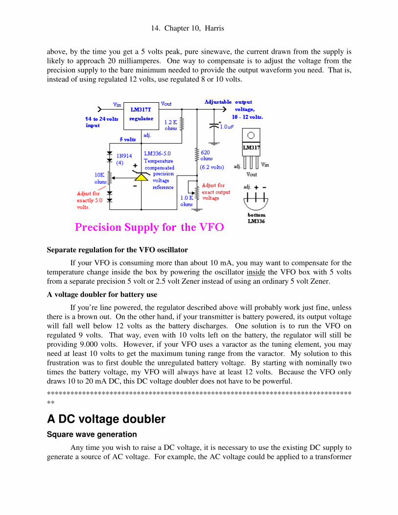
A precision 12 volt power supply
The precision voltage regulator shown below comes from the National Semiconductor
Data Book for linear integrated circuits. This regulator will hold the VFO voltage constant to
within about 2 millivolts. It uses a programmable LM317T regulator. (The "T" at the end
identifies the TO-220 case style.) The output of the big regulator is “modified” with a precision
Zener reference regulator to hold the output voltage constant. The LM317 regulates the voltage
across the 1.2 K ohm resistor to about 1.2 volts. The precision reference then regulates the
voltage across the 620 ohm resistor to exactly 6.2 volts - that is, 1.2 volts plus 5.000 volts. Since
the voltage across the 620 ohm resistor is held constant, the current passing through the 1K
potentiometer is also held constant. Therefore, adjusting the 1K pot can adjust the total voltage.
In order to maintain this high degree of precision, the above regulator just powers the
VFO. When I tried to run other transmitter stages with the precision power supply, the load rose
to several hundred milliamperes. Although the regulator chips were operating within
specifications, the extra load ruined the millivolt precision regulation. I retrofitted my old
capacitor-tuned VFO with the same precision regulator and found the frequency stability became
as good as my newer varactor VFO.
I try to keep my VFO supply current down to less than 10 milliamperes. If you need more
than a 3 volts peak output voltage, you’ll probably find this difficult. In the full circuit shown
Yeah, I know. I promised I
wouldn't use ICs that I couldn't build
myself. I'm afraid precision regulators are
beyond me. I've tried, but my attempts
never exceeded the precision of the most
ordinary IC voltage regulators. I did
manage to build a pretty good voltage
reference consisting of Zeners regulating
other Zeners in a cascade in which some of
the resistors were thermistors.
Unfortunately, the final output was only
stable at tiny voltages and tiny load currents
and I couldn't successfully leverage it up to
useful voltages and currents.
14. Chapter 10, Harris
above, by the time you get a 5 volts peak, pure sinewave, the current drawn from the supply is
likely to approach 20 milliamperes. One way to compensate is to adjust the voltage from the
precision supply to the bare minimum needed to provide the output waveform you need. That is,
instead of using regulated 12 volts, use regulated 8 or 10 volts.
Separate regulation for the VFO oscillator
If your VFO is consuming more than about 10 mA, you may want to compensate for the
temperature change inside the box by powering the oscillator inside the VFO box with 5 volts
from a separate precision 5 volt or 2.5 volt Zener instead of using an ordinary 5 volt Zener.
A voltage doubler for battery use
If you’re line powered, the regulator described above will probably work just fine, unless
there is a brown out. On the other hand, if your transmitter is battery powered, its output voltage
will fall well below 12 volts as the battery discharges. One solution is to run the VFO on
regulated 9 volts. That way, even with 10 volts left on the battery, the regulator will still be
providing 9.000 volts. However, if your VFO uses a varactor as the tuning element, you may
need at least 10 volts to get the maximum tuning range from the varactor. My solution to this
frustration was to first double the unregulated battery voltage. By starting with nominally two
times the battery voltage, my VFO will always have at least 12 volts. Because the VFO only
draws 10 to 20 mA DC, this DC voltage doubler does not have to be powerful.
******************************************************************************
**
A DC voltage doubler
Square wave generation
Any time you wish to raise a DC voltage, it is necessary to use the existing DC supply to
generate a source of AC voltage. For example, the AC voltage could be applied to a transformer
15. Chapter 10, Harris
to produce as high an AC voltage as you need. The high AC voltage would then be rectified
back into DC at the required high voltage. Instead of using a transformer, the voltage doubler
described below uses a capacitive charge pump to raise the voltage. As you’ll see, this
technique is a specialized kind of rectification.
The first task is to convert the DC supply to square wave pulses. It turns out there are
many ways to generate square waves using integrated circuits. For example, I used an
operational amplifier IC to generate the dots in the electronic bug in chapter 9. You may use an
IC if you like, but you might enjoy doing it the hard way. As usual, if you’re new to electronics,
you’ll learn some interesting concepts.
A simplified astable
multivibrator oscillator is
shown to the left. As you can
see, this circuit consists of two
grounded emitter amplifiers
wired so that any change on the
collector of one transistor is
immediately coupled to the
base of the other. Let’s assume
that the capacitor on the left is
charged to a low voltage, say 1
volt. The capacitor on the right
is charged to nearly 12 volts.
The capacitor on the left is charging toward 12 volts through the 7.5 K resistor on the right. As
the positive charge flows out of the capacitor and into the base, the left transistor turns on. This
pulls its collector and its respective capacitor toward ground.
Since the voltage across the capacitor on the right can’t change instantly, the voltage on
the right base is pushed downward to roughly –12 volts. This extreme negative voltage turns off
the right hand transistor. The right hand capacitor with its –12 volts will discharge toward zero
volts since there is now no source of voltage to maintain negative 12 volts. This discharge takes
a significant length of time because the current must bleed into it through the 7.5 K ohm resistor.
Eventually, the voltage on the right transistor’s base rises above +0.6 volts, which will turn that
transistor back on. When the right transistor turns on, it pushes the left hand capacitor back
down to –12 volts turning off the left transistor.
A practical multivibrator
The simplified multivibrator described above oscillates OK, but it doesn’t always start
spontaneously. In fact, you will find that it only runs at a specific range of supply voltage and
must be turned on abruptly. If you turn up the supply voltage gradually, the multivibrator
remains stable with one or both sides turned off and the oscillation never begins.
The unreliability of the simple multivibrator can be fixed by biasing the transistors partly
ON with the 100K ohm resistors. These resistors insure that the capacitors will always be
charging or discharging. Now the circuit will generate square waves even with very low
voltages. When the power supply voltage is turned up slowly, the oscillation will always start.
Also, the ON state of each transistor is maintained longer and a better square wave results.
16. Chapter 10, Harris
Bistable multivibrators are
RAM flip-flops
This is off the subject,
but suppose that the two
capacitors in the above circuit
were replaced with high
resistance resistors. Since there
would be no reactance to charge
or discharge, the circuit would
“lock up” with one transistor
ON and the other OFF. This is
called a stable- or bistable-
multivibrator. If a pulse is introduced to one transistor or the other, the circuit can be made to
“flip-flop” to the opposite stable state in which the OFF transistor turns ON and the ON
transistor turns OFF. The flip-flop circuit is the basis of static RAM memory (SRAM). One
flip-flop can store one bit of information. So long as the supply voltage is applied, the circuit
will “remember” one bit of information indefinitely. Or, it will remember it until another pulse
comes along and resets it to the opposite state. In an integrated circuit SRAM literally millions
of flip-flops are printed on a chip storing megabits of information.
Squaring up the low power square wave to drive a doubler charge pump
Now that we have a low-power, square-wave voltage, we need to clean up the waveform
and amplify it so that we can produce about 30 mA squarewave AC for our VFO power supply.
This is done with a simple buffer amplifier to make it square. A square waveform is important
because the less time that the circuit spends “half turned on,” the more efficient the power supply
will be.
This square wave
buffer is just a high gain
voltage amplifier. During
the sloping, rising input
voltage, the upward slope of
this voltage is exaggerated
by 10 or 20 times. This
diminishes the rise time until
the rise time becomes
negligible.
Diode voltage doubler
17. Chapter 10, Harris
12 volt supply. In other words, 12 volts plus 12 more volts equals 24 volts. This pulsing, 24 volt
signal then charges up the large 100 µF storage capacitor on the right to 24 volts. Provided the
current drawn from the 24 volts supply is small, the capacitor on the right can maintain a
relatively constant voltage approaching 24 volts.
As shown above, the PNP and NPN transistors work together to pull the left hand
capacitor up and push it down. When the PNP transistor is turned on, the bottom end of the
capacitor is connected to ground. In this condition the diode on the left charges up the capacitor
to 12 volts. When the PNP turns off and the NPN turns on, the bottom end of the capacitor is
suddenly shoved “up” and tied to the 12 volt supply line. Since the top of the capacitor is
suddenly 12 volts higher than the supply line, the diode on the left is back-biased and can no
longer charge it. Instead, the diode on the right is now forward biased and will discharge the 12
volts into the storage capacitor on the right. The capacitor on the right charges toward 24 volts
thereby creating twice the original voltage.
Complementary transistors in action
In chapter four I mentioned that it was often convenient to have transistors that work with
opposite polarities. As the drive to one transistor turns it on, the same polarity turns its
complement transistor off. The output is taken off the emitters. In effect, the complementary
transistors connect the output back and forth between ground and the 12 volt supply without any
resistors becoming hot and wasting energy.
By the way, the logic circuits in your personal computer are almost entirely implemented
with integrated circuits made from Complementary N-channel and P-channel MOSFET
transistors. These ICs are called CMOS. By avoiding resistor loads on the FET drains, heating is
minimized and switching speed is maximized.
Use Schottky rectifiers for best efficiency
Now we have loads of extra voltage, even when the battery supplying the transmitter is
nearly exhausted, so there is still plenty of voltage for the precision regulator to generate 12.000
volts. The supply works best if the two diodes in the voltage doubler are power Schottky diodes.
These rectifier diodes only waste about 0.2 volts per diode when conducting current.
How can we “double”
DC voltage using diodes?
The idea is to repeatedly
charge the 33 µF capacitor to
+12 volts as though that
capacitor were a rechargeable
battery. Then the capacitor is
switched out of its “charging
mode” and added like a
battery on top of the existing
18. Chapter 10, Harris
VFO power supply board. It has a variable battery voltage input, precision regulated 12 volts
output.
******************************************************************************
TEMPERATURE COMPENSATON
Supposedly, good VFOs can be built without temperature compensation. Personally, I’ve
never succeeded, but don’t let me be a wet blanket! Go ahead and try. Just leave room on the
PC board to add compensation later.
The challenge is that most VFO parts such as variable capacitors, PC boards, etc. all have
negative temperature coefficients. That is, their capacitance drops as temperature rises. The
strategy of compensation is to substitute C2 or C4 with a capacitor that has an adjustable positive
temperature coefficient. Therefore by paralleling the capacitance with a capacitor that has an
equal but opposite positive temperature coefficient, the capacitance change will be cancelled. I
suggest you start with this method of temperature compensation since it is the easiest.
Positive coefficient trimmer capacitive compensation
If you look in Digi-Key, Mouser, or other parts catalogs you’ll occasionally find trimmer
capacitors with positive temperature coefficients. These are capacitors that increase their
capacitance with rising temperature. I used 20 to 40 pF variable trimmer capacitors made by
Sprague-Goodman, type GCL. I replaced some of the fixed capacitance in the capacitive divider,
C2 and C4, with two positive coefficient trimmers in parallel. The clever part is obtaining both
the correct positive coefficient and the correct amount of positively changing capacitance.
This is done by using a similar negative coefficient trimmer in parallel with the positive
trimmer. By balancing the positive coefficient trimmer directly against an ordinary negative
coefficient trimmer, you can produce a total positive coefficient value that compensates for the
actual negative coefficient of the rest of your LC circuit.
The down side of
Schottky rectifiers is that
they can usually only tolerate
about 30 volts maximum, but
that’s plenty for this
application. In the circuit
shown on the left I used
ordinary 1N4001 silicon
rectifier diodes. Each of
these wastes about 0.7 volts
when turned on.
Consequently, my 24 volt
supply only delivers about 22
volts when the input is 12
volts.
19. Chapter 10, Harris
Adjusting VFO temperature compensation
Put a 500 ohm load on the VFO output and put probes across the load for your scope
and frequency counter. Check that your voltage supply is set where you want it, say 12.000 volts.
It should be rock stable within a millivolt or two. If you’re using a mechanical variable
capacitor, set the capacitor to maximum capacitance. Now adjust the positive and negative
coefficient trimmers to midscale at the desired low-end frequency of the VFO. For example,
with a 5 to 5.5 MHz VFO, you would set it to 5.000 MHz (or just below). Check that you can
still tune up to 5.5 MHz using the main tuning capacitance. If you can’t, you may have to change
C3, or fiddle with C4 or C2. Remember that C2 can also be a positive or negative coefficient
trimmer, depending on what you need.
Now put the lid on the box but don’t screw it down. Watch the frequency drift on your
frequency counter. You will almost certainly see it drift relentlessly up or down. If it is going
down, assume this is caused by increasing temperature in the box. Turn a positive trimmer to
LESS capacitance, then adjust a negative trimmer to restore the frequency back to where you
started. Repeat this again and again until the drift direction reverses. Now it should be going
relentlessly UP. Now take off just a bit of the negative trimmer until the drift comes to a halt.
When you get them balanced well, the frequency will still change, but now it will wander up and
down but soon return to the same frequency. That is, the frequency will no longer march
continuously in the same direction. When you get to this point, you have done as well as you can
with your present set of components. With luck, during any given minute it won’t wander up or
down more than 5 Hz.
******************************************************************************
**
Thermistor temperature compensation
You may find that your positive trimmer capacitance compensator just doesn’t give you
enough positive compensation to do a good job. A thermistor compensation circuit may be just
20. Chapter 10, Harris
what you need. I had good results with the ARRL handbook circuit below.
Resistors are
usually designed to
change as little as possible
with temperature.
However thermistors are
resistors made from
semiconductor that has a
large temperature
coefficient. The
coefficient can either be
positive or negative, and
both kinds can be used in
the above circuit. The
thermistors are placed in a
bridge circuit with a
thermistor on each side of
the bridge. The entire
circuit is powered by a
precision regulated
supply, 5 to 10 volts. By
adjusting the 5K and 500K trimmer pots at the top and middle, the degree and direction of the
compensation can be selected. Tuning the 500K pot to the right selects more positive
compensation. Tuning to the left selects less positive compensation or possibly even negative
compensation. If you need more capacitance, you can always parallel two (or more) varactors.
The tune up is done much like the capacitive compensation version. The good news is that I
found the thermistor-varactor compensation much easier to adjust.
Temperature regulation
Another approach to temperature compensation is to hold the temperature constant by
heating the VFO and regulating the temperature with a thermostat. I built such a device inside
the lid of my cast metal box. The heater had a resistive heater element and a thermistor-
controlled temperature regulation feedback system. The good news was that it regulated the box
temperature to within 0.1 degree Fahrenheit. The bad news was that it took the temperature at
least 30 minutes to stabilize and, when installed in the transmitter, the regulator was trying to
heat the entire transmitter and perhaps the whole room. In other words, a heated VFO box will
need extensive thermal insulation in order to be practical. I gave up on this idea.
In conclusion,
Precision voltage regulation, temperature compensation and careful adjustment can
produce a homebuilt VFO that doesn’t drift like a homebuilt. When you get on the air and
describe your rig as “all homebrew,” the stations you work will (sometimes) shower you with
praise. Enjoy every compliment. If you needed as many prototypes as I did to develop a
reasonably good VFO, you deserve kudos. Actually, the best complements I've had were when I
21. Chapter 10, Harris
yacked with guys for an hour without any complaints about my drift. This was especially true if I
was able to avoid discussing my funky homebrew transmitter. For all they knew, I was using a
first rate modern transceiver.


![Harmonic method of intercomparing the oscillators of the ...Lapham] Intercomparison oj Piezo Oscillators 493 the frequency of the standard to be compared with the reference standard](https://static.documents.pub/doc/80x56/5e6b468a4aa1ea6f7b11df3a/harmonic-method-of-intercomparing-the-oscillators-of-the-lapham-intercomparison.jpg)


