Page 1
1
American Institute of Aeronautics and Astronautics
Variable Wing Span Using the Compliant Spar Concept
Rafic M. Ajaj1 and Michael I. Friswell
2
1College of Engineering, Swansea University, Swansea, SA2 8PP, UK
Erick I. Saavedra Flores3
2Departamento de Ingeniería en Obras Civiles, Universidad de Santiago de Chile,
Av. Ecuador 3659, Santiago, Chile
Askin T. Isikveren4
3Bauhaus Luftfahrt e.V., Lyonel-Feininger-Str.
1 28, Munich, 80807, Germany
and
Hamdi Chaouk5
4Department of Mechanical and Aerospace Engineering,
University of Balamand, Balamand, Lebanon
This paper develops and models the Compliant Spar concept that allows the wing span to be varied to
provide roll control and enhance the operational performance for a medium altitude long endurance
(MALE) UAV. The wing semi-span is split into morphing partitions and the concept maybe incorporated
in each partition; however only the tip partition is considered here. The Compliant Spar is made of
compliant joints arrange in series to allow the partition to be flexible under axial (spanwise) loads but at
the same time stiff enough to resist bending loads. Each compliant joint consists of two concentric
overlapping Aluminium (AL) 2024-T3 tubes joined together using elastomeric material. Under axial
(spanwise) loading, the elastomeric material deforms in shear allowing the overlapping distance between
the tubes to vary and hence the length (in the spanwise direction) of the joint/spar to vary. High fidelity
modelling of the concept is performed. Then, multidisciplinary design optimisation (MDO) studies are
performed to minimise the axial stiffness and the structural mass of the concept for various design
constraints. The flexible skin and actuation system to be used are also addressed.
I. Introduction
ontinuous demands to enhance flight performance and control authority have focused the interest of
aircraft designers on span morphing. Wings with large spans have good range and fuel efficiency, but lack
manoeuvrability and have relatively low cruise speeds. By contrast, aircraft with low aspect ratio wings can fly
faster and become more manoeuvrable, but show poor aerodynamic efficiency [1]. A variable span wing can
potentially integrate into a single aircraft the advantages of both designs, making this emerging technology
especially attractive for military UAVs. Increasing the wingspan, increases the aspect ratio and wing area, and
decreases the spanwise lift distribution for the same lift. Thus, the drag of the wing could be decreased, and
consequently, the range or endurance of the vehicle increased. Unfortunately, the wing-root bending moment
can increase considerably due to the larger span. Thus the aerodynamic, structural, aeroelastic, and control
characteristics of the vehicle should be investigated in the design of variable-span morphing wings. Most span
1 Lecturer in Aerospace Engineering, College of Engineering, Swansea University, Swansea, UK, SA2 8PP,
AIAA member. 2 Professor of Aerospace Structures, College of Engineering, Swansea University, Swansea, UK, SA2 8PP.
3 Lecturer in Civil Engineering Department at the University of Santiago Chile, Av. Ecuador 3659, Santiago,
Chile. 4 Head of Visionary Aircraft Concepts Group, Bauhaus Luftfahrt e.V., Munich 80807, Germany, AIAA
member. 5 Associate rofessor, Department of Mechanical and Aerospace Engineering, University of Balamand,
Balamand, Lebanon.
C
54th AIAA/ASME/ASCE/AHS/ASC Structures, Structural Dynamics, and Materials Conference
April 8-11, 2013, Boston, Massachusetts
AIAA 2013-1451
Copyright © 2013 by Rafic Mohammad Ajaj. Published by the American Institute of Aeronautics and Astronautics, Inc., with permission.
Page 2
2
American Institute of Aeronautics and Astronautics
morphing concepts are based on a telescopic mechanism, following the ideas of Ivan Makhonine, a Russian
expatriate, where the wing outer panel telescoped inside the inner panel to enable span and wing area changes.
The MAK-10 was the first design with a telescopic wing and it first flew in 1931. The mechanism was powered
pneumatically and enabled span increases up to 62% (from 13 to 21m) and area increases up to 57% (from 21 to
33m2) [2]. Blondeau et al. [3] designed and fabricated a three segmented telescopic wing for a UAV. Hollow
fiberglass shells were used to preserve the spanwise aerofoil geometry and ensure compact storage and
deployment of the telescopic wing. To reduce the weight, they replaced the wing spars with inflatable actuators
that could support the aerodynamic loads on the wing (in excess of 73kg/m2). Their telescopic spar design
consisted of three concentric circular aluminium tubes of decreasing diameter and increasing length, connected
by ceramic linear bearings, and deployed and retracted using input pressures of 345–483kPa (50–70psi). The
wing could undergo a 114% change in the aspect ratio, while supporting aerodynamic loads.
Blondeau et al. [4] adopted two identical telescopic spars instead of one, mechanically coupled by the ribs,
to prevent wing twist and fluttering. The new prototype could undergo a 230% change in aspect ratio, and seam
heights were reduced giving less parasitic drag. In its fully deployed condition the telescopic wing could achieve
lift-to-drag ratios as high as 16, which was similar to its solid foam-core wing counterpart. The most dramatic
morphing wing involving span change that has been realized as a wind tunnel prototype is the Agile Hunter by
Lockheed Martin [5-7]. Funded by DARPA within the MAS program, the prototype was based on a military
UAV capable of folding the inner sections of the wing near to the fuselage, to reduce the surface area and drag
during transonic flight at low altitude (also called a Z-wing). The major challenge was the realization of suitable
hinges that connect the two wing portions; the hinges have to sustain the aerodynamic loads but offer a smooth,
continuous aerodynamic surface. Several materials were considered, including silicone-based and Shape
Memory Polymer skins. Wind tunnel tests at Mach 0.6 showed a morphing capability from 0° to 130° over 65s
with a controllable, reliable and precise actuation. Bae et al. [8] performed both static aerodynamic and
aeroelastic studies on the wing of a long-range cruise missile and highlighted some of the benefits and
challenges associated with the design of a morphing wing capable of span change. The total drag decreased by
approximately 25%, and the range increased by approximately 30%. The aeroelastic analysis showed that the
flexibility of the morphing wing structure increased as the wingspan increased. At a given flight condition, the
deformation from the aerodynamic loads was much larger than that of the conventional wing. Static aeroelastic
considerations that a variable-span wing requires increased bending stiffness because the bending deformation is
more significant than twist.
Asymmetrical span morphing can be used for roll control. Ajaj et al. [9] investigated the use of asymmetric
span morphing to replace conventional ailerons and provide roll control for a medium altitude long endurance
(MALE) UAV. In addition, they optimised the rolling strategy to minimise drag for a steady roll manoeuvre.
Seigler et al. [10] investigated asymmetrical span extension for increased manoeuvrability of bank-to-turn cruise
missiles. By formulating a full nonlinear model of the missile, due to the shift of the missile centre of mass and
the dependence of the rolling moment on the angle of attack, they showed that the control authority can be
significantly larger when compared to conventional tail surface control. Improved manoeuvrability, however, is
highly dependent upon the angle of attack, linear actuation speed, and extension length. Moreover, as the mass
of the extending wings becomes large relative to the missile body, the rigid body dynamics can become
increasingly complex and a nonlinear control law was formulated to control the roll, angle of attack, and side
slip angle dynamics in accordance with bank-to-turn guidance. The control method proved to be adept in
tracking commanded inputs while effectively eliminating sideslip. Seigler et al. [11] studied the modelling and
flight control of vehicles with large-scale planform changes. The equations of atmospheric flight were derived in
a general form, methods to integrate the aerodynamic forces examined, and various approaches and methods of
flight control distinguished. A more extensive review on span morphing technology (applications and concepts)
for both fixed-wing and rotary-wing aircraft is given in Barbarino et al. [12].
The main objective of this paper is to develop a structural concept that allows the wing span to be varied to
provide roll control and enhance the operational performance of a MALE UAV. High fidelity modelling and
MDO studies are performed to maximise the ratio of bending to axial stiffness and minimise the structural mass
of the concept. The flexible skin and actuation system to be used are also addressed.
II. Benefits of Span Morphing
Ajaj et al. [13,14] investigated the use of asymmetric span morphing to provide roll control and replace
conventional ailerons. In addition, they assessed the potential benefits of symmetric span morphing in reducing
vortex induced drag, extending endurance, and reducing take-off field length (TOFL) and landing distance (LD)
for a medium altitude long endurance (MALE) UAV. The UAV they considered is similar to the BAE Systems
Herti UAV shown in Fig. 1. The UAV has a maximum lift to drag ratio of about 20 and a maximum endurance
capability of about 18 hours. A representative flight profile, shown in Fig. 2, was assumed in this analysis. The
Copyright © 2013 by Rafic Mohammad Ajaj. Published by the American Institute of Aeronautics and Astronautics, Inc., with permission.
Page 3
3
American Institute of Aeronautics and Astronautics
UAV takes-off with a weight of 800kg and it cruises and loiters for about 18 hours with a speed of 50m/s
(M0.16) at 6100m (20,000ft) and then it descends and lands.
Figure 1. BAE Systems Herti UAV [15].
Figure 2. Mission profile of the UAV.
The design parameters of the vehicle are given in Table 1.
Table 1: Design parameters of the UAV.
Design Parameters Values
MTOW 800 kg
BOW 500 kg
Fuel weight 150 kg
Endurance 18 hrs.
Lift-to-Drag 20
Aerofoil NACA 63-015A
Span 12 m
Chord 1.87 m
Wing area 22.44 m2
MTOW: Maximum take-off weight
BOW: Basic operating weight
Ajaj et al. [13,14] used the Tornado Vortex Lattice Method (VLM) to estimate induced drag. Parasitic drag
(skin-friction and form) were estimated using semi-empirical correlations. Endurance is expected to vary as the
accuracy of the aerodynamic model increases, but the variation will be small as endurance is mainly related to
the loitering flight phase at which the angle of attack is fairly small and the flow is expected to remain attached.
A convergence study was performed to ensure that the prediction of their VLM code is robust with minimal
numerical errors. The outcomes of their study [13,14] can be summarised as
The wing must be able to extend on both sides by up to 22% and must be able to retract on both sides
by up to 22% to provide sufficient roll control over the entire flight profile.
The rolling moment generated by asymmetric span morphing is very sensitive to the angle of attack
(AOA). This sensitivity to AOA doesn’t exist with conventional ailerons. This proves that morphing
Copyright © 2013 by Rafic Mohammad Ajaj. Published by the American Institute of Aeronautics and Astronautics, Inc., with permission.
Page 4
4
American Institute of Aeronautics and Astronautics
structures should not be operated in the same way as conventional control surfaces. The benefits that
can be achieved from coupled manoeuvres must be exploited via the design of “ad hoc” flight control
systems.
Span morphing induces some additional inertial terms in the roll equation of motion. These increase the
importance of the transient response compared to ailerons due to the larger and heavier structure to be
actuated.
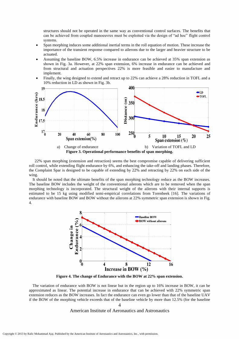
Assuming the baseline BOW, 6.5% increase in endurance can be achieved at 35% span extension as
shown in Fig. 3a. However, at 22% span extension, 6% increase in endurance can be achieved and
from structural and actuation perspectives 22% is more feasible and easier to manufacture and
implement.
Finally, the wing designed to extend and retract up to 22% can achieve a 28% reduction in TOFL and a
10% reduction in LD as shown in Fig. 3b.
a) Change of endurance b) Variation of TOFL and LD
Figure 3. Operational performance benefits of span morphing.
22% span morphing (extension and retraction) seems the best compromise capable of delivering sufficient
roll control, while extending flight endurance by 6%, and enhancing the take-off and landing phases. Therefore,
the Complaint Spar is designed to be capable of extending by 22% and retracting by 22% on each side of the
wing.
It should be noted that the ultimate benefits of the span morphing technology reduce as the BOW increases.
The baseline BOW includes the weight of the conventional ailerons which are to be removed when the span
morphing technology is incorporated. The structural weight of the ailerons with their internal supports is
estimated to be 15 kg using modified semi-empirical correlations from Torenbeek [16]. The variations of
endurance with baseline BOW and BOW without the ailerons at 22% symmetric span extension is shown in Fig.
4.
Figure 4. The change of Endurance with the BOW at 22% span extension.
The variation of endurance with BOW is not linear but in the region up to 16% increase in BOW, it can be
approximated as linear. The potential increase in endurance that can be achieved with 22% symmetric span
extension reduces as the BOW increases. In fact the endurance can even go lower than that of the baseline UAV
if the BOW of the morphing vehicle exceeds that of the baseline vehicle by more than 12.5% (for the baseline
Copyright © 2013 by Rafic Mohammad Ajaj. Published by the American Institute of Aeronautics and Astronautics, Inc., with permission.
Page 5
5
American Institute of Aeronautics and Astronautics
BOW) and 16% (for the BOW without ailerons). This implies that the span morphing system (structure and
actuator) must be as light as possible to maximise the gain in endurance.
In the literature there many span morphing concepts varying from telescopic structures with sliding skins
actuated pneumatically or hydraulically to compliant structures with flexible skins actuated using SMA or
muscles. However, only a limited number of aircraft with span morphing wings has been built and flown as
shown in Fig. 5. There are many reasons for this and they are beyond the scope of this paper. Table 2
summarises the morphing concepts (structure and actuation) used with those aircraft.
Figure 5. Aircraft that flew span morphing wings.
Table 2: Air-vehicles flew with span morphing technology.
Vehicle Category Morphing Structure Skin Actuator
MAK-10 GAA Span Telescopic Sliding Pneumatic
MAK-123 GAA Span Telescopic Sliding Pneumatic
FS-20 Glider Span Telescopic Sliding Screw jacks
FLYRT UAV Span - - -
Virginia Tech UAV Span Telescopic Sliding Rack & pinion
MFX-1 UAV Aspect Ratio &
Sweep
Articulated lattice
structure
Stretchable
GAA: General Aviation Aircraft
Table 2 shows that most of the vehicles used telescopic structures where the morphing partition(s) can slide
in and out through the fixed inboard partition. These vehicles do not require any compliant or flexible skin, as
the sliding/telescopic mechanism allows rigid covers and semi-monocoque construction. This is the main driver
for developing the Complaint Spar concept, to enable a fully compliant structure that allows the coupling of
span and sweep and allows distributed actuation along the span of the wing.
III. The Compliant Spar
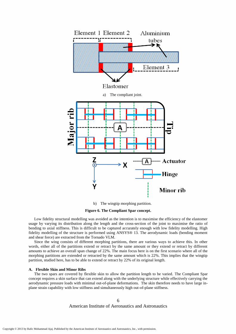
The Complaint Spar concept consists of compliant joints that allow the spar to be flexible under axial
(spanwise) loads but at the same time stiff enough to resist bending loads. The compliant joint (Element 2)
shown in Fig. 6a consists of two concentric overlapping AL 2024-T3 tubes joined together using elastomeric
material. Under axial (spanwise) loading, the elastomeric material deforms in shear allowing the overlapping
distance between the tubes to vary and hence the length (in the spanwise direction) of the joint/spar to vary. The
elastomeric material is bonded to the AL tubes. The bonding process and the manufacturing/integration of the
spar are beyond the scope of this paper.
To assess the feasibility of the Compliant Spar concept, the wing semi-span is split into 5 morphing
partitions and the Compliant Spar is embedded in each partition. In this paper only the wingtip morphing
partition is studied. The entire wing with Compliant Spars will be considered in future work. The wingtip
partition has two Compliant Spars bounded by two major ribs, one at the root and one at the tip. The front spar
is located at 20% of the chord while the rear spar is located at 65% of the chord. A schematic of the Compliant
Spar concept inside the tip morphing partition is shown in Fig. 6b.
Copyright © 2013 by Rafic Mohammad Ajaj. Published by the American Institute of Aeronautics and Astronautics, Inc., with permission.
Page 6
6
American Institute of Aeronautics and Astronautics
a) The compliant joint.
b) The wingtip morphing partition.
Figure 6. The Compliant Spar concept.
Low fidelity structural modelling was avoided as the intention is to maximise the efficiency of the elastomer
usage by varying its distribution along the length and the cross-section of the joint to maximise the ratio of
bending to axial stiffness. This is difficult to be captured accurately enough with low fidelity modelling. High
fidelity modelling of the structure is performed using ANSYS® 13. The aerodynamic loads (bending moment
and shear force) are extracted from the Tornado VLM.
Since the wing consists of different morphing partitions, there are various ways to achieve this. In other
words, either all of the partitions extend or retract by the same amount or they extend or retract by different
amounts to achieve an overall span change of 22%. The main focus here is on the first scenario where all of the
morphing partitions are extended or retracted by the same amount which is 22%. This implies that the wingtip
partition, studied here, has to be able to extend or retract by 22% of its original length.
A. Flexible Skin and Minor Ribs
The two spars are covered by flexible skin to allow the partition length to be varied. The Compliant Spar
concept requires a skin surface that can extend along with the underlying structure while effectively carrying the
aerodynamic pressure loads with minimal out-of-plane deformations. The skin therefore needs to have large in-
plane strain capability with low stiffness and simultaneously high out-of-plane stiffness.
Copyright © 2013 by Rafic Mohammad Ajaj. Published by the American Institute of Aeronautics and Astronautics, Inc., with permission.
Page 7
7
American Institute of Aeronautics and Astronautics
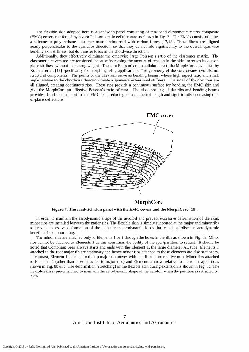
The flexible skin adopted here is a sandwich panel consisting of tensioned elastomeric matrix composite
(EMC) covers reinforced by a zero Poisson’s ratio cellular core as shown in Fig. 7. The EMCs consist of either
a silicone or polyurethane elastomer matrix reinforced with carbon fibres [17,18]. These fibres are aligned
nearly perpendicular to the spanwise direction, so that they do not add significantly to the overall spanwise
bending skin stiffness, but do transfer loads in the chordwise direction.
Additionally, they effectively eliminate the otherwise large Poisson’s ratio of the elastomer matrix. The
elastomeric covers are pre-tensioned, because increasing the amount of tension in the skin increases its out-of-
plane stiffness without increasing weight. The zero Poisson’s ratio cellular core is the MorphCore developed by
Kothera et al. [19] specifically for morphing wing applications. The geometry of the core creates two distinct
structural components. The points of the chevrons serve as bending beams, whose high aspect ratio and small
angle relative to the chordwise direction create a spanwise extensional stiffness. The sides of the chevrons are
all aligned, creating continuous ribs. These ribs provide a continuous surface for bonding the EMC skin and
give the MorphCore an effective Poisson’s ratio of zero. The close spacing of the ribs and bending beams
provides distributed support for the EMC skin, reducing its unsupported length and significantly decreasing out-
of-plane deflections.
Figure 7. The sandwich skin panel with the EMC covers and the MorphCore [19].
In order to maintain the aerodynamic shape of the aerofoil and prevent excessive deformation of the skin,
minor ribs are installed between the major ribs. The flexible skin is simply supported at the major and minor ribs
to prevent excessive deformation of the skin under aerodynamic loads that can jeopardise the aerodynamic
benefits of span morphing.
The minor ribs are attached only to Elements 1 or 2 through the holes in the ribs as shown in Fig. 8a. Minor
ribs cannot be attached to Elements 3 as this constrains the ability of the spar/partition to retract. It should be
noted that Compliant Spar always starts and ends with the Element 1, the large diameter AL tube. Elements 1
attached to the root major rib are stationary and hence minor ribs attached to those elements are also stationary.
In contrast, Element 1 attached to the tip major rib moves with the rib and not relative to it. Minor ribs attached
to Elements 1 (other than those attached to major ribs) and Elements 2 move relative to the root major rib as
shown in Fig. 8b & c. The deformation (stretching) of the flexible skin during extension is shown in Fig. 8c. The
flexible skin is pre-tensioned to maintain the aerodynamic shape of the aerofoil when the partition is retracted by
22%.
Copyright © 2013 by Rafic Mohammad Ajaj. Published by the American Institute of Aeronautics and Astronautics, Inc., with permission.
Page 8
8
American Institute of Aeronautics and Astronautics
a) Schematic of a minor rib.
b) Partition before extension.
c) Partition after extension.
Figure 8. Minor ribs to support the flexible skin.
B. Structural Modelling in ANSYS
The concentric tubes, made from AL 2024-T3, are modelled using the SHELL 181 element in ANSYS®.
SHELL181 is suitable for analysing thin to moderately-thick shell structures. It has four nodes with six degrees
of freedom per node. Furthermore, it is suitable for linear large rotation, and both full and reduced integration
schemes are supported [20]. The elastomer is modelled using the SOLID 185 element. The SOLID 185 is used
for 3 dimensional modelling of solid structures. It has eight nodes, each node having three degrees of freedom
(translations in the nodal x, y, and z directions). The element formulation allows deformations of nearly
incompressible elastoplastic materials and fully incompressible hyperelastic materials to be simulated [20]. A
rigid beam element is used to model the major rib at one side of the partition where the other side is clamped.
The rigid beam is modelled using the MPC 184 element which is well suited for linear, large rotation
applications. MPC184 is multipoint constraint element that applies kinematic constraints between nodes [20].
The major rib ensures that the front and rear spar work in parallel in resisting the out-of-plane and the in-plane
loads.
Copyright © 2013 by Rafic Mohammad Ajaj. Published by the American Institute of Aeronautics and Astronautics, Inc., with permission.
Page 9
9
American Institute of Aeronautics and Astronautics
i. Assumptions
The analysis in this paper is based on the following assumptions:
The strain in the elastomer due to span extension is below the value at which the behaviour of the elastomer
becomes nonlinear.
Nonlinear geometric effects are neglected.
The elastomer is assumed to be isotropic and fully incompressible.
ii. Elastomer distribution
As highlighted before, the compliant joint consists of two concentric overlapping AL 2024-T3 tubes joined
together using elastomeric material. The design of such a compliant joint is quite challenging. The bending
stiffness must be high while the axial stiffness (spanwise direction) must be very low to minimise the actuation
requirements. In addition, the weight of the partition must be low to maintain the benefits of the span morphing
technology. Polyurethane elastomer is used in this analysis and the material properties are given in Table 3.
Table 3: Material properties of Polyurethane elastomer [21].
Properties Value
10 MPa
45 MPa
1250 kg/m3
0.5
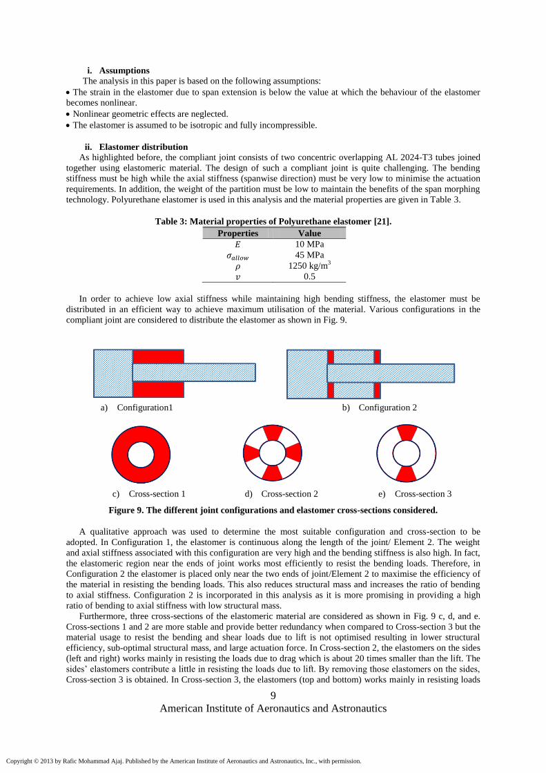
In order to achieve low axial stiffness while maintaining high bending stiffness, the elastomer must be
distributed in an efficient way to achieve maximum utilisation of the material. Various configurations in the
compliant joint are considered to distribute the elastomer as shown in Fig. 9.
a) Configuration1 b) Configuration 2
c) Cross-section 1 d) Cross-section 2 e) Cross-section 3
Figure 9. The different joint configurations and elastomer cross-sections considered.
A qualitative approach was used to determine the most suitable configuration and cross-section to be
adopted. In Configuration 1, the elastomer is continuous along the length of the joint/ Element 2. The weight
and axial stiffness associated with this configuration are very high and the bending stiffness is also high. In fact,
the elastomeric region near the ends of joint works most efficiently to resist the bending loads. Therefore, in
Configuration 2 the elastomer is placed only near the two ends of joint/Element 2 to maximise the efficiency of
the material in resisting the bending loads. This also reduces structural mass and increases the ratio of bending
to axial stiffness. Configuration 2 is incorporated in this analysis as it is more promising in providing a high
ratio of bending to axial stiffness with low structural mass.
Furthermore, three cross-sections of the elastomeric material are considered as shown in Fig. 9 c, d, and e.
Cross-sections 1 and 2 are more stable and provide better redundancy when compared to Cross-section 3 but the
material usage to resist the bending and shear loads due to lift is not optimised resulting in lower structural
efficiency, sub-optimal structural mass, and large actuation force. In Cross-section 2, the elastomers on the sides
(left and right) works mainly in resisting the loads due to drag which is about 20 times smaller than the lift. The
sides’ elastomers contribute a little in resisting the loads due to lift. By removing those elastomers on the sides,
Cross-section 3 is obtained. In Cross-section 3, the elastomers (top and bottom) works mainly in resisting loads
Copyright © 2013 by Rafic Mohammad Ajaj. Published by the American Institute of Aeronautics and Astronautics, Inc., with permission.
Page 10
10
American Institute of Aeronautics and Astronautics
due to lift and therefore maximising the efficiency of the material usage. In addition, Cross-section 3 increases
the ratio of bending to axial stiffness (lower actuation forces). Therefore, Configuration 2 with Cross-section 3
is adopted for the compliant joints.
Figure 10 shows the Compliant Spars of the wingtip partition labelled and meshed in ANSYS® 13. The
distance separating the centres of the spars is 0.85 m. Each spar consists of 6 joints (which is the general case).
The spars are clamped on one side (root of the partition) and on the other side (tip of the partition) they are
constrained together to artificially model the effect of the major rib at the tip.
Figure 10. The Compliant Spars in ANSYS® 13.
It should be noted that the representative Compliant Spars shown in Fig. 8 are not the optimised version of
the concept that has minimal axial stiffness and sufficient bending stiffness. The deformations of those spars
under 1g aerodynamic loads and 22% span extension in different views are shown in Fig. 11.
Copyright © 2013 by Rafic Mohammad Ajaj. Published by the American Institute of Aeronautics and Astronautics, Inc., with permission.
Page 11
11
American Institute of Aeronautics and Astronautics
a) Isometric view.
b) Side view.
Figure 11. Deformed Compliant Spars in various views.
C. Loads: Aerodynamics and Actuation
The Tornado VLM was used for aerodynamic predictions. Tornado VLM is a linear aerodynamics code, and
discounts wing thickness and viscous effects [22,23]. These limitations imply that Tornado can only be used for
angles of attack up to 8-10° for slender wings. The aerodynamic forces and moments are extracted from
Tornado VLM. These forces and moments are used to estimate an equivalent shear force and equivalent torque
that are placed at the end of the partition (tip) on the midpoint of the connecting element/major rib. The UAV
can experience a load factor up to 6g due to vertical gusts [24]. This implies that the tip morphing partition
(mainly the elastomer) must withstand those high limit loads without excessive deformations and/or permanent
plastic deformation especially if the span morphing is used to provide various functionalities including roll
control which is essential for the safety and survivability of the UAV. Therefore, the aerodynamic loads
extracted from Tornado VLM are amplified to simulate the 6g scenario.
In addition to the aerodynamic loads, an axial (spanwise) extension equivalent to 22% of the partition length
is imposed at the end of the partition to simulate the 22% extension scenario.
Finally, the self-weight of the partition is also considered in the analysis. This provides some inertial relief
for the aerodynamic loads. The worst case loading scenario, full extension at 6g vertical gust, is considered in
this chapter with a of 1.5.
Copyright © 2013 by Rafic Mohammad Ajaj. Published by the American Institute of Aeronautics and Astronautics, Inc., with permission.
Page 12
12
American Institute of Aeronautics and Astronautics
IV. MDO Studies
Two MDO studies are performed in this section. In the first study, the axial stiffness of the partition is
minimised for different geometric constraints. In the second study, the optimum solutions obtained from
minimising the axial stiffness are further optimised to minimise the structural mass of the partition. These
studies are performed using an MDO suite that consists of the GA optimiser, Tornado VLM, and ANSYS® 13.
A flowchart describing the MDO suite is shown in Fig. 12. It should be noted that aeroelastic coupling is not
considered.
Figure 12. Flowchart for the MDO suite.
The “Matlab GA Toolbox”, developed by Chipperfield et al. [25,26] was incorporated in this analysis. A
fitness value is assigned to every individual of the initial population through an objective function that assesses
the performance of the individual in the problem domain. Then, individuals are selected based on their fitness
index and crossover between them is performed to generate new offspring. Finally, mutation of the new
offspring is performed to ensure that the probability of searching any subspace of the problem is never zero.
These abovementioned processes iterate until the optimum solution is achieved depending on the convergence
criteria of the problem.
A. Axial Stiffness
Reducing the axial stiffness of the Compliant Spars is a main design driver as it determines the magnitude of
the actuation forces and power. The actuation forces and power have a direct impact on the size, weight, and
number of the actuators required. The partition original length before morphing is 1.2 m (20% of the wing
semi-span). A schematic showing the design variables of the compliant joint is shown in Fig. 13.
Copyright © 2013 by Rafic Mohammad Ajaj. Published by the American Institute of Aeronautics and Astronautics, Inc., with permission.
Page 13
13
American Institute of Aeronautics and Astronautics
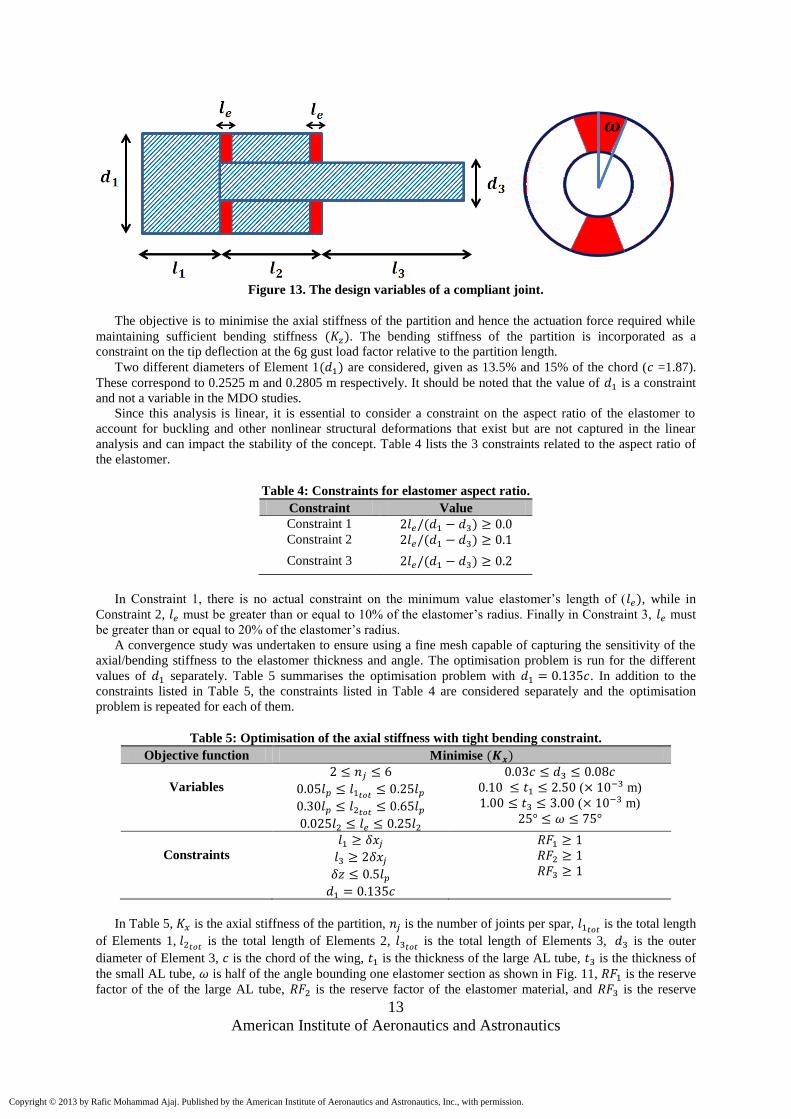
Figure 13. The design variables of a compliant joint.
The objective is to minimise the axial stiffness of the partition and hence the actuation force required while
maintaining sufficient bending stiffness . The bending stiffness of the partition is incorporated as a
constraint on the tip deflection at the 6g gust load factor relative to the partition length.
Two different diameters of Element 1 are considered, given as 13.5% and 15% of the chord ( =1.87).
These correspond to 0.2525 m and 0.2805 m respectively. It should be noted that the value of is a constraint
and not a variable in the MDO studies.
Since this analysis is linear, it is essential to consider a constraint on the aspect ratio of the elastomer to
account for buckling and other nonlinear structural deformations that exist but are not captured in the linear
analysis and can impact the stability of the concept. Table 4 lists the 3 constraints related to the aspect ratio of
the elastomer.
Table 4: Constraints for elastomer aspect ratio.
Constraint Value
Constraint 1
Constraint 2
Constraint 3
In Constraint 1, there is no actual constraint on the minimum value elastomer’s length of ( , while in
Constraint 2, must be greater than or equal to 10% of the elastomer’s radius. Finally in Constraint 3, must
be greater than or equal to 20% of the elastomer’s radius.
A convergence study was undertaken to ensure using a fine mesh capable of capturing the sensitivity of the
axial/bending stiffness to the elastomer thickness and angle. The optimisation problem is run for the different
values of separately. Table 5 summarises the optimisation problem with . In addition to the
constraints listed in Table 5, the constraints listed in Table 4 are considered separately and the optimisation
problem is repeated for each of them.
Table 5: Optimisation of the axial stiffness with tight bending constraint.
Objective function Minimise
Variables
( m)
( m)
Constraints
In Table 5, is the axial stiffness of the partition, is the number of joints per spar, is the total length
of Elements 1, is the total length of Elements 2,
is the total length of Elements 3, is the outer
diameter of Element 3, is the chord of the wing, is the thickness of the large AL tube, is the thickness of
the small AL tube, is half of the angle bounding one elastomer section as shown in Fig. 11, is the reserve
factor of the of the large AL tube, is the reserve factor of the elastomer material, and is the reserve
Copyright © 2013 by Rafic Mohammad Ajaj. Published by the American Institute of Aeronautics and Astronautics, Inc., with permission.
Page 14
14
American Institute of Aeronautics and Astronautics
factor of the small AL tube, is the axial deformation of the compliant joint, and is the out of plane
deformation of the tip end of the morphing partition. , , and can be obtained from Equations (1), (2),
(3), and (4) respectively as
(1)
and
(2)
and
(3)
and
(4)
The constraints are essential to ensure that the ultimate stresses in the AL tubes and the elastomer are
below the corresponding allowable strengths. In addition to the constraints, two geometric constraints are
added to ensure that when the partition is retracted by 22%, the outer tubes (Elements 1) of the adjacent joints
don’t collide with each other.
After investigating the convergence criteria of the GA, the number of generations of the optimiser is fixed to
100 with 100 individuals per generation. For the sake of accuracy and consistency, each optimisation run is
repeated 5 times. Table 6 summarises the outcomes of the study.
Table 6: Minimum axial stiffness at for different constraints.
Parameter Constraint 1 Constraint 2 Constraint 3
(kN/m) 0.65 1.25 5.10
(kN/m) 5.40 6.00 5.40
8.30 4.80 1.10
(kg) 14 14.5 18
2 2 2
(m) 0.29 0.29 0.28
(m) 0.56 0.52 0.42
(m) 0.35 0.39 0.50
(m) 0.0075 0.008 0.017
(m) 0.058 0.090 0.074
( m) 2.20 1.90 1.30
( m) 3.00 3.00 3.00
26.0° 25.0° 25.0°
The MDO study is repeated for and the outcomes are summarised in Table 7.
Copyright © 2013 by Rafic Mohammad Ajaj. Published by the American Institute of Aeronautics and Astronautics, Inc., with permission.
Page 15
15
American Institute of Aeronautics and Astronautics
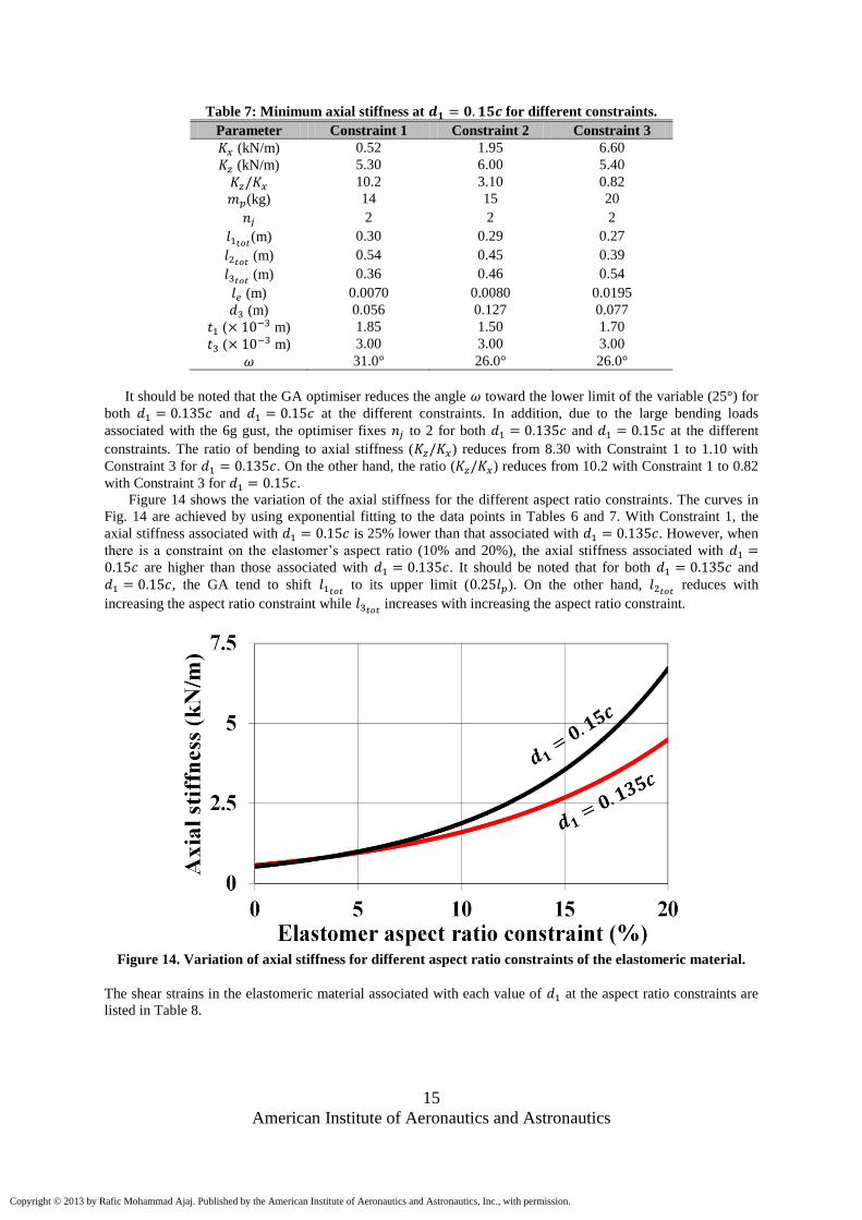
Table 7: Minimum axial stiffness at for different constraints.
Parameter Constraint 1 Constraint 2 Constraint 3
(kN/m) 0.52 1.95 6.60
(kN/m) 5.30 6.00 5.40
10.2 3.10 0.82
(kg) 14 15 20
2 2 2
(m) 0.30 0.29 0.27
(m) 0.54 0.45 0.39
(m) 0.36 0.46 0.54
(m) 0.0070 0.0080 0.0195
(m) 0.056 0.127 0.077
( m) 1.85 1.50 1.70
( m) 3.00 3.00 3.00
31.0° 26.0° 26.0°
It should be noted that the GA optimiser reduces the angle toward the lower limit of the variable (25°) for
both and at the different constraints. In addition, due to the large bending loads
associated with the 6g gust, the optimiser fixes to 2 for both and at the different
constraints. The ratio of bending to axial stiffness ( ) reduces from 8.30 with Constraint 1 to 1.10 with
Constraint 3 for . On the other hand, the ratio ( ) reduces from 10.2 with Constraint 1 to 0.82
with Constraint 3 for .
Figure 14 shows the variation of the axial stiffness for the different aspect ratio constraints. The curves in
Fig. 14 are achieved by using exponential fitting to the data points in Tables 6 and 7. With Constraint 1, the
axial stiffness associated with is 25% lower than that associated with . However, when
there is a constraint on the elastomer’s aspect ratio (10% and 20%), the axial stiffness associated with are higher than those associated with . It should be noted that for both and
, the GA tend to shift to its upper limit ( ). On the other hand,
reduces with
increasing the aspect ratio constraint while increases with increasing the aspect ratio constraint.
Figure 14. Variation of axial stiffness for different aspect ratio constraints of the elastomeric material.
The shear strains in the elastomeric material associated with each value of at the aspect ratio constraints are
listed in Table 8.
Copyright © 2013 by Rafic Mohammad Ajaj. Published by the American Institute of Aeronautics and Astronautics, Inc., with permission.
Page 16
16
American Institute of Aeronautics and Astronautics
Table 8: Shear strain of the elastomer for the optimum solutions.
Parameter
C1 C2 C3 C1 C2 C3
Shear strain ( )
(radian)
0.94 1.03 0.98 0.87 1.05 0.93
C1: Constraint 1, C2: Constraint 2, C3: Constraint 3
The shear strains listed in Table 8 are very large but well below the allowable shear strain of Polyurethane
elastomer. However, at such large strains, the stress-strain curve becomes nonlinear and this is not captured in
this analysis. Future work will address geometric and material nonlinearity associated with the Compliant Spar.
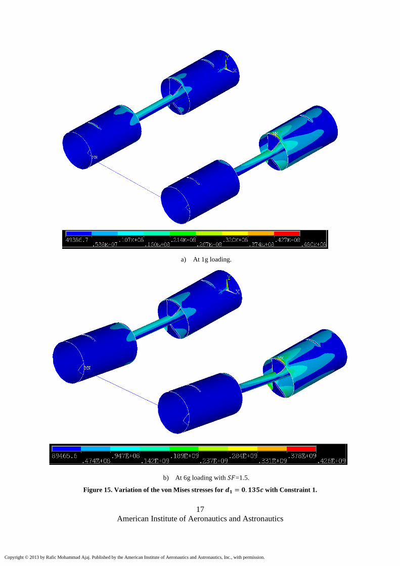
Furthermore, the variation of the von Mises stresses on the following optimum solutions are shown in Fig.
15 and 16:
with Constraint 1
with Constraint 1
Figures 15 & 16 show the stress variations for the optimum solutions at the normal 1g loading and at the
ultimate 6g loading scenarios.
It should be noted that the front spar is subject to higher bending loads than the rear spar due to the
equivalent torque applied, since the spars resist the equivalent torque mainly by bending. The front spar bends
up due to the torque which adds up to the bending loads due the equivalent shear force, while the rear spar bends
down due to the torque which subtracts from the bending loads due to the equivalent shear force. This results in
the front spar carrying higher bending loads and hence subject to higher stresses. This is obvious in Fig. 15 & 16
where the front spar has higher von Mises stresses especially at the interface between the elastomer and the AL
tubes close to the root of the partition (clamped). The interface region is highly loaded as the bending loads are
transferred from the small AL tube to the large tube through the elastomer. The contact area between the
elastomer and Element 1 is relatively small resulting in high stress concentrations.
Figures 15 & 16 show that increasing from 13.5% to 15% of the chord reduces the von Mises stresses in
the large AL tube (Element 1) and at the interface between the tubes and the elastomeric material.
Copyright © 2013 by Rafic Mohammad Ajaj. Published by the American Institute of Aeronautics and Astronautics, Inc., with permission.
Page 17
17
American Institute of Aeronautics and Astronautics
a) At 1g loading.
b) At 6g loading with =1.5.
Figure 15. Variation of the von Mises stresses for with Constraint 1.
Copyright © 2013 by Rafic Mohammad Ajaj. Published by the American Institute of Aeronautics and Astronautics, Inc., with permission.
Page 18
18
American Institute of Aeronautics and Astronautics
a) At 1g loading.
b) At 6g loading with =1.5.
Figure 16. Variation of the von Mises stresses for with Constraint 1.
Copyright © 2013 by Rafic Mohammad Ajaj. Published by the American Institute of Aeronautics and Astronautics, Inc., with permission.
Page 19
19
American Institute of Aeronautics and Astronautics
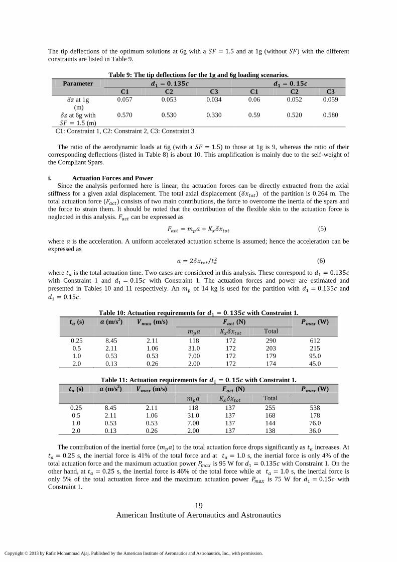
The tip deflections of the optimum solutions at 6g with a and at 1g (without ) with the different
constraints are listed in Table 9.
Table 9: The tip deflections for the 1g and 6g loading scenarios.
Parameter
C1 C2 C3 C1 C2 C3
at 1g
(m)
0.057 0.053 0.034 0.06 0.052 0.059
at 6g with
(m)
0.570 0.530 0.330 0.59 0.520 0.580
C1: Constraint 1, C2: Constraint 2, C3: Constraint 3
The ratio of the aerodynamic loads at 6g (with a ) to those at 1g is 9, whereas the ratio of their
corresponding deflections (listed in Table 8) is about 10. This amplification is mainly due to the self-weight of
the Compliant Spars.
i. Actuation Forces and Power
Since the analysis performed here is linear, the actuation forces can be directly extracted from the axial
stiffness for a given axial displacement. The total axial displacement of the partition is 0.264 m. The
total actuation force ( ) consists of two main contributions, the force to overcome the inertia of the spars and
the force to strain them. It should be noted that the contribution of the flexible skin to the actuation force is
neglected in this analysis. can be expressed as
(5)
where is the acceleration. A uniform accelerated actuation scheme is assumed; hence the acceleration can be
expressed as
(6)
where is the total actuation time. Two cases are considered in this analysis. These correspond to
with Constraint 1 and with Constraint 1. The actuation forces and power are estimated and
presented in Tables 10 and 11 respectively. An of 14 kg is used for the partition with and
.
Table 10: Actuation requirements for with Constraint 1.
(s) (m/s2) (m/s) (N) (W)
Total
0.25 8.45 2.11 118 172 290 612
0.5 2.11 1.06 31.0 172 203 215
1.0 0.53 0.53 7.00 172 179 95.0
2.0 0.13 0.26 2.00 172 174 45.0
Table 11: Actuation requirements for with Constraint 1.
(s) (m/s2) (m/s) (N) (W)
Total
0.25 8.45 2.11 118 137 255 538
0.5 2.11 1.06 31.0 137 168 178
1.0 0.53 0.53 7.00 137 144 76.0
2.0 0.13 0.26 2.00 137 138 36.0
The contribution of the inertial force ( ) to the total actuation force drops significantly as increases. At
s, the inertial force is 41% of the total force and at s, the inertial force is only 4% of the
total actuation force and the maximum actuation power is 95 W for with Constraint 1. On the
other hand, at s, the inertial force is 46% of the total force while at s, the inertial force is
only 5% of the total actuation force and the maximum actuation power is 75 W for with
Constraint 1.
Copyright © 2013 by Rafic Mohammad Ajaj. Published by the American Institute of Aeronautics and Astronautics, Inc., with permission.
Page 20
20
American Institute of Aeronautics and Astronautics
The actuation energy is mainly needed to strain the elastomeric material. The majority of this actuation
energy is stored in the form of strain energy in the elastomer. Once the locking mechanism is released, the
stored strain energy returns the partition to its original configuration. This is an advantage for the Compliant
Spar in comparison with telescopic spars that require actuation energy to morph and unmorph them.
After thorough consideration of the state-of-the-art actuation technologies, electromechanical actuators are
selected for the Compliant Spar concept due to their good performance and low associated weight. The lead
angle of the screw is low to provide a self-locking mechanism without the need for continuous power supply to
hold in any specific position.
ii. Shear Strain Constraint
In the previous section, the wingtip partition was designed to have a tip deflection smaller than or equal to
50% of its length at the ultimate loading scenario (6g with a ). Therefore, the GA optimiser reduced the
number of joints to 2 per spar to maintain sufficient bending stiffness for the different constraints. This resulted
in higher shear strains in the elastomer (due to lower number of joints). In this section, the partition is designed
to have a tip deflection smaller than or equal to 10% of its length at the 1g normal loading scenario. The tip
deflections at the ultimate loading scenario are not considered. Constraints on the thicknesses of the AL tubes
are added to ensure that they don’t fail or undergo permanent deformation when subject to the ultimate loads.
The main driver of this section is to reduce the shear strain in the elastomer. Therefore a constraint on the shear
strain in the elastomer is imposed to ensure that it doesn’t exceed 0.75 rad. The analysis is performed for both
and with Constraint 1. The optimisation problems are summarised in Tables 12
( ) and 13 ( ).
Table 12: Minimise axial stiffness for at the 1g flight condition.
Objective function Minimise
Variables
rad
Constraints
=2.20 ( m)
=3.00 ( m)
Table 13: Minimise axial stiffness for at the 1g flight condition.
Objective function Minimise
Variables
rad
Constraints
=1.85 ( m)
=3.00 ( m)
The outcomes of the optimisation problems are summarised in Table 14.
Copyright © 2013 by Rafic Mohammad Ajaj. Published by the American Institute of Aeronautics and Astronautics, Inc., with permission.
Page 21
21
American Institute of Aeronautics and Astronautics
Table 14: Outcomes of the optimisation problems.
Parameter Constraint 1
Constraint 1
(kN/m) 0.80 0.66
(kN/m) 2.55 2.55
3.20 3.90
(kg) 18 20
4 4
(m) 0.73 0.73
(m) 0.21 0.21
(m) 0.26 0.26
(m) 0.007 0.007
(m) 0.070 0.090
68 50 (rad) 0.63 0.61
Table 14 shows that shear strain drops from 0.94 rad when the partition was designed for the ultimate
loadings (without a shear strain constraint) to 0.63 rad when it is designed for the 1g normal loading (with shear
strain constraint) for with Constraint 1, and it drops from 0.87 rad to 0.61 for with
Constraint 1. This is mainly due to the higher . Increasing reduces the shear strain and the axial stiffness
but it also reduces significantly the bending stiffness. In order to maintain the bending stiffness, and are
increased by the optimiser which in the end results in a higher axial stiffness when compared to the case of
ultimate loads without a shear strain constraint. It should be noted that the values of ,
, and are the
same for and . The GA optimiser maximises the to its upper limit to increase the
bending stiffness of the partition. The variation of von Mises stresses on the optimal solutions is shown in Fig.
17. The lower shear strains in the elastomer ensure that the assumption of linear elastic behaviour is valid.
Copyright © 2013 by Rafic Mohammad Ajaj. Published by the American Institute of Aeronautics and Astronautics, Inc., with permission.
Page 22
22
American Institute of Aeronautics and Astronautics
a) For .
b) For .
Figure 17. Variation of the von Mises stresses for the optimum solutions at 1g with a shear strain
constraint.
Copyright © 2013 by Rafic Mohammad Ajaj. Published by the American Institute of Aeronautics and Astronautics, Inc., with permission.
Page 23
23
American Institute of Aeronautics and Astronautics
B. Structural Mass
After minimising the axial stiffness of the partition for different values of at different geometric/aspect
ratio constraints, the optimum solutions are further optimised to reduce the structural mass without affecting the
ratio of bending to axial stiffness. Only two cases are considered (without the shear strain constraint) in this
section. These correspond to with Constraint 2 and with Constraint 2. Tables 15 and
16 summarise the optimisation problem for each case.
Table 15: Minimise structural mass for with Constraint 2.
Objective function Minimise
Variables
( m)
( m)
Constraints
m
m
Table 16: Minimise structural mass for with Constraint 2.
Objective function Minimise
Variables
( m)
( m)
Constraints
m
m
The number of generations for each case is reduced to 50 with 100 individuals per generation, because the
number of design variables has reduced in comparison to the axial stiffness optimisation. Table 17 summarises
the outcomes of the study.
Table 17: Minimum structural mass of the partition with Constraint 2.
Parameter Constraint 2
Constraint 2
(kg) 8 9
(kN/m) 1.24 1.95
2 2
(m) 0.38 0.31
(m) 0.52 0.45
(m) 0.30 0.44
(m) 0.008 0.008
(m) 0.090 0.127
( m) 0.75 0.94
( m) 0.90 0.80
25.0° 26.0°
For , the mass of the partition (only the spars) reduces from 14.5 kg to 8 kg, which corresponds
to a 45% reduction in the structural mass. On the other hand, for the mass reduces from 15 kg to 9
kg which corresponds to a 40% reduction in the structural mass of the partition.
Copyright © 2013 by Rafic Mohammad Ajaj. Published by the American Institute of Aeronautics and Astronautics, Inc., with permission.
Page 24
24
American Institute of Aeronautics and Astronautics
V. Conclusions
The Compliant Spar has shown to be a promising concept capable of delivering the required variation in the
partition’s span. High fidelity modelling of the concept was performed using ANSYS® 13. MDO studies using
a Genetic Algorithm optimiser were conducted to maximise the ratio of bending to axial stiffness and to
minimise the structural mass of the concept to enhance its feasibility and preserve the benefits of span
morphing. The actuation force is mainly required to strain the spar. An actuation power of about 95 W is
required to morph the two Compliant Spars in 1 s. Sandwich skin panels consisting of elastomeric matrix
composite (EMC) covers reinforced by a zero Poisson’s ratio cellular core are adopted to maintain the
aerodynamic shape of the aerofoil.
Acknowledgments
The research leading to these results has received funding from the European Research Council under the
European Union's Seventh Framework Programme (FP/2007-2013) / ERC Grant Agreement n. [247045]. E.I.
Saavedra Flores acknowledges the support of the Department of Civil Engineering, University of Santiago,
Chile.
References 1McCormik, B.W. Aerodynamics, Aeronautics and Flight Mechanics, 2nd Edition, Wiley, New York, 1995. 2Weisshaar, T.A. “Morphing Aircraft Technology – New Shapes for Aircraft Design,” RTO-MP-AVT-141, Neuilly-sur-
Seine, France, 2006. 3Blondeau J. and Pines D. “Design and Testing of a Pneumatic Telescopic wing for Unmanned Aerial Vehicles,” AIAA,
Journal of Aircraft, 44(4), 2007. 4Blondeau J., Richeson, J. and Pines D.J. “Design, Development and Testing of a Morphing Aspect Ratio Wing Using an
Inflatable Telescopic Spar,” 44th AIAA/ASME/ASCE/AHS/ASC Structures, Structural Dynamics and Materials Conference,
Norfolk, VA, AIAA 2003-1718, 2003. 5Ivanco, T.G., Scott, R.C., Love, M.H., Zink, S. and Weisshaar, T.A., “Validation of the Lockheed Martin Morphing
Concept with Wind Tunnel Testing,” 48th AIAA/ASME/ASCE/AHS/ASC Structures, Structural Dynamics, and Materials
Conference, Honolulu, Hawaii, AIAA 2007-2235, 2007. 6Bye, D.R. and McClure, P.D. ‘‘Design of a Morphing Vehicle,’’ 48th AIAA/ASME/ASCE/AHS/ASC Structures,
Structural Dynamics, and Materials Conference, 23-26 April, Honolulu, HI, AIAA 2007-1728, 2007. 7Love, M.H., Zink, P.S., Stroud, R.L., Bye, D.R., Rizk, S. and White, D. “Demonstration of Morphing Technology
through Ground and Wind Tunnel Tests,” 48th AIAA/ASME/ASCE/AHS/ASC Structures, Structural Dynamics, and
Materials Conference, Honolulu, Hawaii, AIAA 2007-1729, 2007. 8Bae, J.S., Seigler, T. M., and Inman, D. J., "Aerodynamic and Aeroelastic Characteristics of a Variable-Span Morphing
Wing," Journal of Aircraft, 2005, Vol. 42, No. 2, pp. 528-534. 9Ajaj, R.M., Friswell, M.I., Saavedra-Flores, E.I., et al. “Span Morphing: A Conceptual Design Study,” 20th
AIAA/ASME/AHS Adaptive Structures Conference, 23-26 April 2012, Honolulu, Hawaii, USA, paper AIAA-2012-1510,
2012. 10Seigler, T.M., Bae, J.S. and Inman, D.J. ‘‘Flight Control of a Variable Span Cruise Missile,’’ In: Proceedings of 2004
ASME International Mechanical Engineering Congress and Exposition, 13-19 November, Anaheim, CA, Paper No.
IMECE2004-61961, 2004. 11Seigler, T.M., Neal, D.A., Bae, J.S., and Inman, D.J., "Modeling and Flight Control of Large-Scale Morphing
Aircraft," Journal of Aircraft, Vol. 44, No. 4, 2007, pp. 1077-1087. 12Barbarino, S., Bilgen, O., Ajaj, R.M., Friswell, M.I., and Inman, D.J., “A Review of Morphing Aircraft,” Journal of
Intelligent Material Systems and Structures, 22(9), 823-877, June 2011. 13Ajaj, R.M., Saavedra Flores, E.I., Friswell, M.I., Isikveren, A.T., Allegri, G., Adhikari, S., and Chaouk, H. 2013. “An
Integrated Conceptual Design Study
Using Span Morphing Technology,” Journal of Intelligent Material Systems and Structures, (Submitted). 14Ajaj, R.M., Friswell, M.I., Saavedra Flores, E.I., Little, O., and Isikveren, A.T. 2012. “Span Morphing: A Conceptual
Design Study,” 20th AIAA/ASME/AHS Adaptive Structures Conference, 23-26th April, Honolulu, Hawaii, USA, AIAA-
2012-1510. 15Austin, R. 2010. Unmanned Aircraft Systems: UAV Design, Development, and Deployment, John Wiley & Sons Ltd,
pp.313. 16Torenbeek, E. “Development and Application of a Comprehensive, Design-sensitive Weight Prediction Model for
Wing Structures of Transport Category Aircraft,” Report LR-693, Delft University of Technology, September 1992. 17Bubert, E.A., Woods, B.K.S., Lee, K., Kothera, C.S., and Wereley, N.M., 2010, "Design and Fabrication of a Passive
1D Morphing Aircraft Skin," Journal of Intelligent Material Systems and Structures, 21(17): 1699-1717. DOI:
10.1177/1045389X10378777 18Murray, G., Gandhi, F., and Bakis, C., “Flexible Matrix Composite Skins for One-dimensional Wing Morphing,”
Journal of Intelligent Material Systems and Structures, April 2010, Vol. 21, No. 17, pp. 1771-1781. DOI:
10.1177/1045389X10369719.
Copyright © 2013 by Rafic Mohammad Ajaj. Published by the American Institute of Aeronautics and Astronautics, Inc., with permission.
Page 25
25
American Institute of Aeronautics and Astronautics
19Kothera, C.S., Woods, B.K.S., Bubert, E.A., Wereley, N.M., and Chen, P.C., “Cellular Support Structures used for
Controlled Actuation of Fluid Contact Surfaces,” US Patent No. 7,931,240, Techno-Sciences, Inc., Beltsville, MD, issued on
Apr. 26, 2011. 20ANSYS® Academic Research, Release 13.0. 2013. Help System, ANSYS, Inc. 21Groover, M.P. 2010. Fundamentals of Modern Manufacturing: Materials. Processes, and Systems, 4th Edition, John
Wiley & Sons. 22Melin, T. “A Vortex Lattice MATLAB Implementation for Linear Aerodynamic Wing Applications,” Master’s Thesis,
Royal Institute of Technology (KTH), Department of Aeronautics, Sweden, 2000. 23Melin, T. “User’s guide and reference manual for Tornado,” Royal Institute of Technology (KTH), Department of
Aeronautics, Sweden, 2000. 24Neubauer, M., Gunthe,r G., and Fullhas, K. “Structural design aspects and criteria for military UAV,” RTO-MP-AVT
145 UAV Design Processes and Criteria 2007. 25Chipperfield, A. J. and Fleming, P. J. “The Matlab Genetic Algorithm Toolbox,” IEE Colloquium on Applied Control
Techniques using Matlab, Digest No.1995/014, 1996. 26Chipperfield, A. J., Fleming, P. J., and Fonseca, C. M. “Genetic Algorithm Tools for Control Systems Engineering,”
Proc.1st Int. Conf. Adaptive Computing in Engineering Design and Control, Plymouth Engineering Design Centre, UK, 21-
22 September, pp. 128-133, 1994.
Copyright © 2013 by Rafic Mohammad Ajaj. Published by the American Institute of Aeronautics and Astronautics, Inc., with permission.