Page 1
Variables & signals.Simulation
Module: Electronics & Telecommunications, 3rd year
Digital Systems Design withHardware Description Languages
1Rajda & Kasperek © 2019 Dept. of Electronics, AGH UST
Page 2
Agenda
Signals in VHDLprocesses, declarations, delays, hazards
SimulationDelta-Time cycle, sensitivity list,resolution function, attributes
2Rajda & Kasperek © 2019 Dept. of Electronics, AGH UST
Page 3
Signals in VHDL
Structural description
entity COMPARE isport (A, B: in bit;
C: out bit);end COMPARE;
architecture STRUCTURAL of COMPARE issignal I: bit; -- internal signal – no direction!
component XR2 port (X, Y: in bit; Z: out bit);end component ;component INV port (X: in bit; Z: out bit);end component ;
beginU0: XR2 port map (A, B, I);U1: INV port map (I, C);
end STRUCTURAL;
XR2 INV
U0 U1
IC
A
B
X
Y
Z X Z
3Rajda & Kasperek © 2019 Dept. of Electronics, AGH UST
Page 4
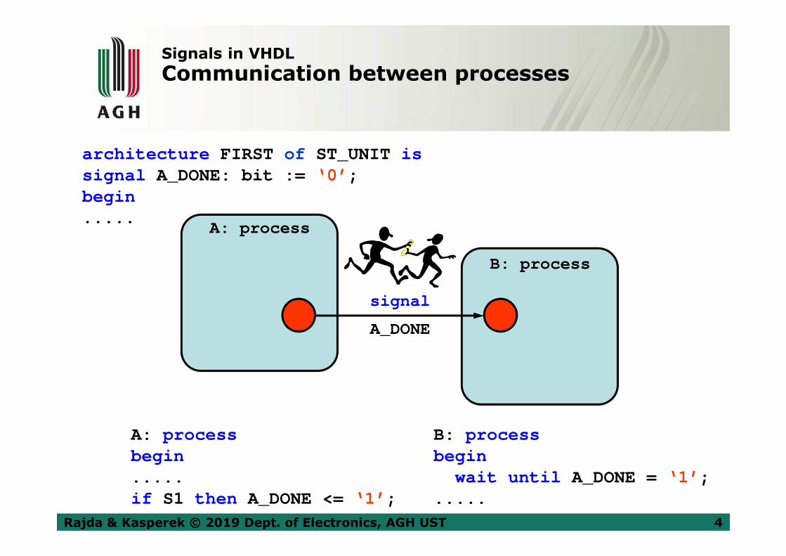
Signals in VHDL
Communication between processes
architecture FIRST of ST_UNIT issignal A_DONE: bit := ‘0’ ;begin.....
A: processbegin.....if S1 then A_DONE <= ‘1’ ;
B: processbegin
wait until A_DONE = ‘1’ ;.....
A: process
B: process
signal
A_DONE
4Rajda & Kasperek © 2019 Dept. of Electronics, AGH UST
Page 5
Signals in VHDL
Communication between processes
• Processes can communicate with each otherby giving the value to the signal(s).
• Process may suspend its operation and waitfor the change on its input signal.
• Variables declared in the process may not passtheir values to other processes.
• VHDL‘93 defines the global variables that may be used for communication between processes.
5Rajda & Kasperek © 2019 Dept. of Electronics, AGH UST
Page 6
Signals in VHDL
Signal declarations in VHDL
• Signals may be declared in:
� packets – global signals� declaration section in entity - signals global
for entity
- ports: in , out , inout , buffer- other declarations
� declaration section in architecture - signalslocal for architecture
• Signals are initialized with := operator
• Values are given to signals with <= operator
6Rajda & Kasperek © 2019 Dept. of Electronics, AGH UST
Page 7
Signals in VHDL
Signal declarations in VHDL
Signals global for entity:entity BOARD_DESIGN is
port (DATA_IN: in bit;DATA_OUT: out bit);
signal SYS_CLK: bit := ‘1’ ;end BOARD_DESIGN;
Signals local for architecture:architecture DATA_FLOW of BOARD_DESIGN is
signal INT_BUS: bit;begin..........
Global signals:package SIGDEC is
signal VCC: bit := ‘1’ ;signal GROUND: bit := ‘0’ ;
end SIGDEC;
7Rajda & Kasperek © 2019 Dept. of Electronics, AGH UST
Page 8
Signals in VHDL
Signal declarations in VHDL
A declaration of signal in the port statement of entity should specify:
the name of the signal, its direction, type and optionally the initial value.
Syntax:port (name [, more_names]: direction type [:= expression] [; more_ports]);
Examples:
port (DATA_IN: in bit; DATA_OUT: out bit);
port (B, A: in MyLib.MyPkg.MyType);
Direction Usage
in The right side of the assignment to the variable or signal
out The left side of the assignment to the variable or signal
inout Both above
buffer As above, but only one driver (not used in practice)
8Rajda & Kasperek © 2019 Dept. of Electronics, AGH UST
Page 9
Signals in VHDL
Feedback
Question: What is the most likely direction of the signal Q?
DffD
C
Q
9Rajda & Kasperek © 2019 Dept. of Electronics, AGH UST
Page 10
Signals in VHDL
Feedback
entity ...port (D: in ...
C: in ...Q: buffer ... );
end entity ;
architecture wrongbegin
process (C)begin
if C and C’event thenQ <= Q xor D;
end if ;end process ;
end wrong;
The rules of connections between the modules require correspondingmodes of ports, eg: buffer � buffer . But this is not convenient...
entity ...port (D: in ...
C: in ...Q: out ... ); -- OUT direction
end entity ;
architecture goodsignal : T ... -- T aux signal
beginprocess (C)begin
if C and C’event thenT <= T xor D; -- T usage
end if ;end process ;Q <= T; -- concurrent assignment
end good;
� �
10Rajda & Kasperek © 2019 Dept. of Electronics, AGH UST
Page 11
Signals in VHDL
Transport delay
Modeling of connections is made using the transport delay.All the changes of the signal value are propagated, regardlessof their duration.
Syntax:signal <= transport expression after transport-delay;
Example:Y <= transport A after 10 ns; A Y
time(ns) 15 30 45 60
Y
A
11Rajda & Kasperek © 2019 Dept. of Electronics, AGH UST
Page 12
Signals in VHDL
Inertial delay
Modeling of elements is done using inertial delays (default).Only these changes of the signal value, which last longer thanthe delay, are propagated.
Syntax:
signal <= [inertial ] expression after inertial-delay;
Example:Y <= A after 10 ns; A Y
time(ns) 15 30 45 60
Y
A
12Rajda & Kasperek © 2019 Dept. of Electronics, AGH UST
Page 13
Signals in VHDL
Inertial delay
VHDL-93 allows the modeling of elements that respond to pulses shorter than the delay of these elements.
Syntax:
signal <= reject reject-delay inertial expression after inertial-delay;
Example:Y <= reject 4 ns inertial A after 10 ns;
A Y
time(ns) 15 30 45 60
Y
A
13Rajda & Kasperek © 2019 Dept. of Electronics, AGH UST
Page 14
Signals in VHDL
Modeling the delays in process
Assigning values to the signals is sequential inside the processes,but concurrent outside of them.
Inside the processes, the signal assignments are stopped until thesimulation cycle is run. This is triggered by the execution of the waitstatement.
Example:
processbegin
sys_clk <= not (sys_clk) after 50 ns;int_bus <= data_in after 10 ns;data_out <= my_function (int_bus) after 10 ns;wait .....
end process ;
14Rajda & Kasperek © 2019 Dept. of Electronics, AGH UST
Page 15
Signals in VHDL
Modeling the delays with signals
Assignment statements may contain values of the signals for several various moments in time. This feature is useful for describing the clock signals and other repetitive waveforms.
Example:S <= ‘1’ after 4 ns, ‘0’ after 7 ns;T <= 1 after 1 ns, 3 after 2 ns, 6 after 8 ns;
Inside the process, each signal should have only one source at a time. Otherwise, only the last assignment is taken into account.
Example:processbegin
xyz <= 1 after 5 ns; -- despite of the time...xyz <= 2 after 4 ns; -- ...only this occures!...pqr <= 10 after 5 ns; -- ...and of course this one.
wait .....
15Rajda & Kasperek © 2019 Dept. of Electronics, AGH UST
Page 16
Signals in VHDL
Modeling the delays with signals
signal X, Y: integer;processbegin
wait on Y;X <= Y + 1 after 10 ns;
In the above example, X takes the new value exactly after 10 ns,not after 9.999 or 10.001 ns.
Specification of delays is ignored by synthesis tools.
signal X: integer;process .....begin.....X <= X + 1 after 10 ns;.....
1 x
16Rajda & Kasperek © 2019 Dept. of Electronics, AGH UST
Page 17
Signals in VHDL
Zero delay
Example:
entity VAR isport (A: in bit_vector ( 0 to 7);
INDEX: in integer range 0 to 7;OUTPUT: out bit);
end VAR;
architecture VHDL_1 of VAR isbegin
processbegin
OUTPUT <= A(INDEX); -- 0 ns delaywait .....; -- wait initializes the assignment
.....end VHDL_1;
17Rajda & Kasperek © 2019 Dept. of Electronics, AGH UST
Page 18
Signals in VHDL
Variables versus signals
Main differences between the assignments of value to variables and signals
Signal assignments Variable assignments
• according to time regimes • no time regimes
• delays taken into account • no delays
• after fulfilling the condition in wait • immediate
18Rajda & Kasperek © 2019 Dept. of Electronics, AGH UST
Page 19
Signals in VHDL
Examples:
X <= 1; -- 0 ns delaywait .....; -- assignment occures after execution of wait
X <= Y; -- 0 ns delaty – signals swapY <= X;wait .....; -- both assignment occure after wait execution
V := 1; -- variable assignemnt occures immediatelyS <= V;A := S; -- A receives the previous value of S wait .....; -- S receives V value (=1) after wait executes
X <= 1;X <= 2;wait for 0 ns; -- after wait execution X recevies value =2
19Rajda & Kasperek © 2019 Dept. of Electronics, AGH UST
Page 20
Signals in VHDL
Hazards
entity MUX isport (Ain, Bin: in bit;
SEL: in boolean;Y: out bit);
end MUX;
architecture WRONG of MUX issignal MUXVAL: integer range 0 to 1;
beginprocessbegin
MUXVAL <= 0;if (SEL) then
MUXVAL <= MUXVAL + 1;end if ;case MUXVAL is
when 0 => Y <= Ain after 10 ns;when 1 => Y <= Bin after 10 ns;
end case ;wait on Ain, Bin, SEL;
end process ;end WRONG;
20Rajda & Kasperek © 2019 Dept. of Electronics, AGH UST
Page 21
Signals in VHDL
Hazards
entity MUX isport (Ain, Bin: in bit;
SEL: in boolean;Y: out bit);
end MUX;
architecture BETTER of MUX isbegin
processvariable MUXVAL: integer range 0 to 1; -- variable!
beginMUXVAL := 0; -- variable!if (SEL) then
MUXVAL := MUXVAL + 1; -- variable!end if ;case MUXVAL is -- variable!
when 0 => Y <= Ain after 10 ns;when 1 => Y <= Bin after 10 ns;
end case ;wait on Ain, Bin, SEL;
end process ;end BETTER;
21Rajda & Kasperek © 2019 Dept. of Electronics, AGH UST
Page 22
Simulation
Signals versus variables
Question:How will above counters count ?
architecture sig of counter issignal SIG: ...beginprocess (CLK)begin
if CLK and CLK'event thenSIG <= SIG + 1;if SIG = 9 then
SIG <= 0; end if;
end if;end process ;
architecture var of counter isbeginprocess (CLK)
variable VAR: ...beginif CLK and CLK'event then
VAR := VAR + 1;if VAR = 9 then
VAR := 0; end if;
end if;end process ;
Rule: Must the newly assigned value be used in the same run of simulationloop? If so, then use the variable. In other cases – use the signal (slowersimulation of signals �).
22Rajda & Kasperek © 2019 Dept. of Electronics, AGH UST
Page 23
Simulation
Simulation cycle
• Former simulators: One-List Algorithm (evaluation and assignment).• VHDL simulators: Two-List Algorithm (evaluation / assignment).
Example (in process):A <= B;B <= A;
Simulation of events with zero delay time is performed during the fictional time unit called delta-time. It is a complete cycle of a simulation, but without advancing the time counter:
• simulator models the events with zero delay time, using the delta-time cycle,
• events executed at the same time are simulated during the delta-timein a given order,
• logic connected with them is then resimulated to propagate changes for the next cycle,
• delta-time cycles are repeated until no changes are detected.
23Rajda & Kasperek © 2019 Dept. of Electronics, AGH UST
Page 24
Simulation
Simulation cycle
time
signals assignmentsprocess execution,
expressions evaluation
Enter Begin Middle End Leave
24Rajda & Kasperek © 2019 Dept. of Electronics, AGH UST
Page 25
Simulation
Simulation cycle
Simulation of concurrent assignments with ∆-cycles.
Example:X <= A and B;Y <= not X;
time(ns) 15 30 45 60
B
A
X
30ns+0 ∆ 50ns+0 ∆
Y
30ns+1 ∆ 50ns+1 ∆
A YX
B
25Rajda & Kasperek © 2019 Dept. of Electronics, AGH UST
Page 26
Simulation
Simulation cycle
Question: What are the values of X and A after one cycleof the delta-time?
processbegin
X <= 1;X <= 2;A <= X;X <= 3;
wait for 0 ns;
26Rajda & Kasperek © 2019 Dept. of Electronics, AGH UST
Page 27
Simulation
wait statement
wait statement variants:
• wait on A, B;Suspends the execution until the event on A or B occures.
• wait until A > 10;Suspends the execution until the event on A occures andthe condition A > 10 is met.
• wait for 10 ns;Suspends the execution for 10ns time.
• wait ;Suspends the execution forever. Used as ‘kill’.
27Rajda & Kasperek © 2019 Dept. of Electronics, AGH UST
Page 28
Simulation
Simulation and wait statement
Rather than wait statement, the user can specify the list of signals
that activate a process (called a 'sensitivity list'). These signals are
listed in parentheses after the process keyword.
This is equivalent to the wait statement, occurring at the end of
the process. The process may contain either the list or such a waitstatement.
Przykład:process (CLK) processbegin begin..... ............... ..........<statements> <statements>..... ............... wait on CLK;end process ; end process ;
28Rajda & Kasperek © 2019 Dept. of Electronics, AGH UST
Page 29
Simulation
Sensitivity list
Question:
What is the difference in the behavior of the two following processes?
process (A, B)beginS <= A;T <= B;V <= S or T;end process ;
process (A, B, S, T)beginS <= A;T <= B;V <= S or T;end process ;
29Rajda & Kasperek © 2019 Dept. of Electronics, AGH UST
Page 30
Simulation
Resolution function
VHDL allows to drive signals from many sources, but:
• all drivers must be placed in a separate processes or in different concurrent assignments,
• for such signals there must be declared a resolution function,
• this function is pre-declared for the std_logic type. This is the preferred type of objects (it's easier to use one type in the whole project), but does not allow for detection (during compilation) of accidental connections of two or more drivers. This is only possible during the simulation.
30Rajda & Kasperek © 2019 Dept. of Electronics, AGH UST
Page 31
Simulation
Resolution function
architecture SEQUENTIAL of TRISTATE issignal Ain,Bin,Asel,Bsel,Sout: STD_LOGIC;
begin
A: process (Ain,Asel)begin
Sout <= ‘Z’ ;if (Asel= ‘1’ ) then
Sout <= Ain;end if ;
end process ;
B: process (Bin,Bsel)begin
Sout <= ‘Z’ ;if (Bsel= ‘1’ ) then
Sout <= Bin;end if ;
end process ;end SEQUENTIAL;
Asel
Bsel
Ain
Bin
Sout
architecture CONCURRENT of TRISTATE issignal Ain,Bin,Asel,Bsel,Sout: STD_LOGIC;begin
Sout <= Ain when Asel = ‘1’ else ‘Z’ ;Sout <= Bin when Bsel = ‘1’ else ‘Z’ ;
end CONCURRENT;
31Rajda & Kasperek © 2019 Dept. of Electronics, AGH UST
Page 32
Simulation
Resolution function – STD_LOGIC_1164
TYPE std_ulogic IS ( 'U' , 'X' , '0' , '1' , 'Z' , 'W' , 'L' , 'H' , '-' );
TYPE std_ulogic_vector IS ARRAY (NATURAL RANGE<>) OF std_ulogic;
FUNCTION resolved (s : std_ulogic_vector) RETURNstd_ulogic;
SUBTYPEstd_logic IS resolved std_ulogic;
TYPE std_logic_vector IS ARRAY (NATURAL RANGE<>) OF std_logic;
TYPE stdlogic_table IS ARRAY (std_ulogic, std_ulogic) OF std_ulogic;
CONSTANTresolution_table : stdlogic_table := (
--------------------------------------------------
--| U X 0 1 Z W L H - | |
--------------------------------------------------
( 'U' , 'U' , 'U' , 'U' , 'U' , 'U' , 'U' , 'U' , 'U' ), -- | U |
( 'U' , 'X' , 'X' , 'X' , 'X' , 'X' , 'X' , 'X' , 'X' ), -- | X |
( 'U' , 'X' , '0' , 'X' , '0' , '0' , '0' , '0' , 'X' ), -- | 0 |
( 'U' , 'X' , 'X' , '1' , '1' , '1' , '1' , '1' , 'X' ), -- | 1 |
( 'U' , 'X' , '0' , '1' , 'Z' , 'W' , 'L' , 'H' , 'X' ), -- | Z |
( 'U' , 'X' , '0' , '1' , 'W' , 'W' , 'W' , 'W' , 'X' ), -- | W |
( 'U' , 'X' , '0' , '1' , 'L' , 'W' , 'L' , 'W' , 'X' ), -- | L |
( 'U' , 'X' , '0' , '1' , 'H' , 'W' , 'W' , 'H' , 'X' ), -- | H |
( 'U' , 'X' , 'X' , 'X' , 'X' , 'X' , 'X' , 'X' , 'X' )); -- | - |
32Rajda & Kasperek © 2019 Dept. of Electronics, AGH UST
Page 33
Simulation
Resolution function – STD_LOGIC_1164
FUNCTION resolved (s: std_ulogic_vector ) RETURNstd_ulogic IS
VARIABLE result : std_ulogic := 'Z' ; -- weakest state default
BEGIN
-- The test for a single driver is essential otherwi se the
-- loop would return 'X' for a single driver of '-' and that
-- would conflict with the value of a single driver unresolved
-- signal.
IF (s'LENGTH = 1) THEN RETURNs(s'LOW);
ELSE
FOR i IN s'RANGE LOOP
result := resolution_table(result, s(i));
END LOOP;
END IF ;
RETURNresult;
END resolved;
33Rajda & Kasperek © 2019 Dept. of Electronics, AGH UST
Page 34
Simulation
Resolution function
Function:
• returns one value,
• has all the arguments in input mode,
• passes the arguments by their values.
Resolution function:
• is required when the signal (node) is controlled by more than one driver,
• performs the arbitration of signals,
• is invoked in case of change in any of the signal drivers,
• receives an array of signals for arbitration,
• is a user-defined function,
• is associated with a subtype.
34Rajda & Kasperek © 2019 Dept. of Electronics, AGH UST
Page 35
Signals in VHDL
Timing attributes of signals
• signal_name‘event - returns TRUE if an event has occurred
on signal in the current simulation cycle
• signal_name‘last_event - returns the amount of time since last event
occurred on signal
• signal_name‘last_value - returns the previous value of signal before
last event occurred on it
Examples:
if CLK’event and CLK=‘1’ then ...
if SD_DAT'event and (SD_DAT=‘H’ or SD_DAT=‘Z’ ) andSD_DAT'last_value= ‘1’ then ...
Defined in libraries functions rising_edge and falling_edge :
if rising_edge(CLK) then ...are equivalent to statements like:
if CLK’event and CLK=‘1’ and CLK’last_value= ‘0’ then ...
35Rajda & Kasperek © 2019 Dept. of Electronics, AGH UST
Page 36
Signals in VHDL
Timing attributes of signals
time(ns) 15 30 45 60
S
S’event
S’last_value
15 20 25 0 5 10 0 5 10 15 20 S’last_event
36Rajda & Kasperek © 2019 Dept. of Electronics, AGH UST
Page 37
Simulation
Predefined attributes
Predefined attributes allow to get information about objects, types, subprograms, etc.
Signal attributes:
37Rajda & Kasperek © 2019 Dept. of Electronics, AGH UST
Page 38
Simulation
Predefined attributes
Attributes of scalar types:
Attributes of discrete and physical types and subtypes:
Attributes of array types and array-type objects:
38Rajda & Kasperek © 2019 Dept. of Electronics, AGH UST
Page 39
To be continued…
39Rajda & Kasperek © 2019 Dept. of Electronics, AGH UST