24
® dental & technik VARIOstar K 50 T 50 1 Operation Manual 01-2018 en brushless Handpiece

®
dental & technik
VARIOstarK50T50
www.zubler.de 1Operation Manual 01-2018
en
brushlessHandpiece

2 2Page

33Page
Important instructions and warnings 1. For your safety, please read all operating instructions before putting the device
into operation. 2. Observe the occupational health and safety regulations of the employer’s liability
insurance. 3. Before starting, ensure the supply voltage corresponds to the data on the type plate. 4. Remove the chuck-/service-tools before switching the device on. 5. Provide good lighting, safety glass shields, eye protection and an extraction
system at the workplace. 6. The handpiece is intended exclusively for dry grinding. 7. Before using the handpiece, make sure the tool is seated firmly and cannot be
pulled out. 8. Use only functional, certified tools (drill bits, milling bits, cutting disks, polishing
tools, grinding tools, etc.) and observe the tool manufacturer’s instructions for use (e.g. maximum permissible speed of rotation).
9. Make sure that the handpiece does not start unintentionally or run unsupervised. 10. Operate the handpiece only with a tool or pin locked in the chuck. 11. Do not turn the chuck while the handpiece is rotating. 12. Clean the chuck regularly according to the instructions (never use compressed air
for cleaning / see section 2.1). 13. Repair and maintenance work on the electrical part of the equipment may only be
performed by an approved or certified repair technician. 14. Electrical devices may not be used in a damp or wet environment. 15. For 115V, use the grounded power cable SVT3x18AWG with IEC socket and
grounded plug. 16. Any interruption in the protective ground conductor inside and outside the device
or loosening of the protective ground connection can lead to the device posing a threat to the operator. Intentional interruption is not permitted.
17. In case of defects or damage where safe operation is no longer ensured, the device must be secured against unintentional use.
18. This device is not suitable for use in potentially explosive environments or on patients.

4 4
Contents0. Introduction Page 5 0.1 Declaration of conformity 0.2 General notes 0.3 Scope of delivery K50 0.4 Commissioning K50 0.5 Scope of delivery T50 0.6 Commissioning T50
1. Operation Page 10 1.1 Handling K50 kneecontroller 1.2 Handling D50 tabletop controller 1.3 Handling the handpiece
2. Maintenance Page 15 2.1 Changing the fuse in the controller 2.2 Malfunction 2.3 Cleaning and replacing the chuck 2.4 Replacing the motor cable 2.5 Spindle change is simple 2.6 Troubleshooting
3. Data Page 20 3.1 Technical data 3.2 Scope of delivery VARIOstar K50 3.3 Scope of delivery VARIOstar T50 3.4 Product overview VARIOstar and Spare parts
4. Safety notes Page 22
5. Warranty terms Page 23
Page

0.
55
Thank you!
We are delighted that you have chosen the Zubler VARIOstar D50 and we hope that you will enjoy working with it. The constant further development of our technology is based on cooperation with experienced dental technicians. Our primary goal is to construct dental equipment of maximum quality, flexibility and sustaina-bility. Performance and profitability are the basic prerequisites for this.
In order to ensure trouble-free usage, ple-ase read the operation manual carefully.
Introduction
0.1 Declaration of conformity
Page
We, Zubler Gerätebau GmbH Buchbrunnenweg 26 89081 Ulm Jungingen
hereby declare that the products
VARIOstar K50VARIOstar T50conform to the regulations of the following EU directives:
2006/42/EC Machinery Directive
2014/35/EU Low Voltage Directive
2014/30/EU EMC Directive
This declaration loses its validity if the products are modified without our agreement.
Kurt Zubler Chief Executive Officer
Fig. 1

12
1
3
21
19 11
2
417
18
20
6 6
1 Knee controller
2 Handpiece
3 Table mount
4 Handpiece stand
11 On/Off switch
12 Digital speed display
13 Socket for handpiece
14 Socket for data cable 15 Socket for external display
16 Power cord connector
17 Flat spanner
18 Chuck tool
19 Knee plate
20 Power cord
21 Fixing knob
22 Assembly diagram
0.3 Scope of delivery: VARIOstar K50 knee controller
Functional principle: Thanks to its special brushless design, the VARIOstar K50/T50 handpiece enables smooth, fatigue-free and thus economical working in continuous operation. The device is constantly moni-tored for overload through microprocessor control. An additional thermal fuse provides the handpiece with increased safety.
0.2 General notes
Fig . 2
Page

1615
14
13
3
ZUBLER Gerätebau GmbHBuchbrunnenweg 26D-89081 UlmTel. +49(0)731 1452-0 / www.zubler.de
VARIOstar K50Drehzahl 50.000/minSpannung AC 230VLeistung max. 270WF: T2AK50 / 00-11111-22
Made in Geramay
77
Fasten the table mount 3 at your workplace with the help of the assembly diagram 22. You can find the assembly diagram between the knee controller 1 and the table mount 3.
Hook the knee controller 1 into the table mount 3 and push the knee controller 1 into the table mount 3 to the stop; secu-re the knee controller with the fixing knob 21.
Connecting the handpiece
Connect the VARIOstar handpiece 2 to the socket 13 (align to the notch) and secure the plug by twisting the ring.
Place the motor handpiece 2 in the handpiece stand 4.
Connecting the power cable
n Compare the voltage specification on the type plate with the mains voltage.
n If they match, plug the power cable into socket 16.
n Then plug the power plug into the main power socket.
0.4 Installing the VARIOstar K50 knee controller
Type plate(see below)
Fig . 4
Fig . 3
Page
Connecting the SL-AP data cable (Zubler suction only!)
Connect socket 14 with the data socket of your Zubler suction unit (align to notch and secure by turning). The data connec-tion enables a disturbance free working.
If using the data cable SL-AP the power cord 20 must not be plugged into the power socket of the suction unit.

6
2
17 18
20
4
12
24
5
T2
23
11
8 8
2 Handpiece
4 Handpiece stand
5 Tabletop controller T50
6 VARIO foot pedal
11 On/Off switch
12 Digital speed display
13 Socket for handpiece
14 Socket for data cable
16 Power cord connector
26 Socket for VARIO foot pedal
20 Power cord
23 Tool tray
24 Speed knob
0.5 Scope of delivery: Tabletop controller VARIOstar T50
Page
Fig . 5

1326
1614
Zubler Gerätebau
numberplate
Tension XXXXXX
Number:
Fone:
ZUBLER Gerätebau GmbHBuchbrunnenweg 26D-89081 UlmTel. +49(0)731 1452-0 / www.zubler.de
VARIOstar T50Drehzahl 50.000/minSpannung AC 230VLeistung max. 270WF: T2AK50 / 00-11111-22
Made in Geramay
99
Connecting the handpiece
Connect the VARIOstar handpiece 2 to socket 13 (align to notch and secure by turning).
Installing the VARIOstar T50 desktop controller
Connecting the knee-/foot-pedal
Connect the VARIOstar Foot Pedal 6 to socket 26 (align to notch and secure by turning).
Connecting the power cable
After comparing the Power Supply data with the Voltage requirement data on the type plate, plug the Power Cord 20 into Power Cord Connection 16, then into the Power Supply or Wall Outlet.
Connecting the SL-AP data cable (Zubler suction only!)
Connect socket 14 control unit with the data socket of your Zubler suction unit (align to notch and secure by turning). The data connection enables a distur-bance free working.
If using the data cable SL-AP the power cord 20 must not be plugged into the power socket of the suction unit.
Page
Fig . 6
Fig . 7
Type plate

Without written modi�cation from you to SERIART G2 within 24 hours conditions above are considered as agreed and accepted
MOD. 47 rev .03 Car tiglio25-03-2015
Overlay
ZUBLER
Leonardo Seno�eni
Polyplate
date
description
customer
product line
drawing by
ATTENTION !!! this drawing may contain modi�cations necessar y to the technical feasibility of the ar ticle
Glossy P olicarbonate 175mlike Alicia
Material 1 Material 2
ZUBFROPOL0000 glossy/matt Acrilyc Adhesivelike Alicia
Chrome - lik e Alicia button
Ral 7011
HKS 15
Matt br ushed - lik e Alicia
Glossy tansparent
Colors FinishCode
modif. rev01 date
sheetsdeliver y
notes
General tollerance ±0.2
MATT ZONE GLUE ZONE
EMBOSSED
GLOSSY ZONE NO GLUE ZONE
11.50 mm
15.50 mm
1.
T2
T3
L3
T1 L1 L212
T45 0
10 10
Operation
The handpiece 2 is started by pressing the knee plate 19. Due to the wide range of movement you can control the speed with ease.
Cruise control
The cruise control is enabled by pressing pushbutton T1, LED L1 lights up.
Pressing and holding the knee plate 19 for 3 sec. on the desired speed will acti-vate the cruise control and the handpiece is running even without pressing the knee plate 19.
To stop the handpiece, press the knee plate 19 again or press pushbutton T1 to disable the cruise control, LED L1 is no longer lit.
Turn the controller ON (I) using the mains switch 11.
The speed display 12 indicates the pre-selected speed. You can change the speed with pushbutton T4 (+)or T3 (-).
1.1 Operating the VARIOstar K50 knee controller
12 Digital speed display
L1 LED Automatic Speed Control
L2 LED safety switch
L3 LED anticlockwise rotation
T1 Automatic speed control
T2 Safety switch
T3 - pushbutton / counterclock-wise rotation
T4 + pushbutton / clockwise rotation
Page
Fig . 8

12
1
1911
1111
Speed limit
The VARIOstar K50 is equipped with an adjustable speed limiter to limit the maxi-mum speed (e.g. 10k rpm for cutting disc).
Press pushbutton T2 to deactivate the speed limiter, LED L2 lights up.
Press pushbutton T2 again to activate the speed limiter, LED L2 is no longer lit.
The speed limiter is factory set to 40k rpm.
Changing the speed limit
Press and hold pushbutton T2 until LED L2 starts flashing. Adjust the maximum speed with pushbutton T4 (+) or T3 (-). (max. 40k rpm).
To save the setting press pushbutton T2 again, LED L2 no longer flashes.
Changing the direction of rotation
Changing to CCW:
Switch ON (I) the control unit with the mains switch 11, while pressing and hol-ding pushbutton T3, LED L3 lights up.
Changing to CW:
Switch ON (I) the control unit with the mains switch 11, while pressing and hol-ding pushbutton T4, LED L3 is no longer lit.
The rotational direction is factory set to CW.
Fig. 9
Page
Caution: Observe the tool manufacturers specified speeds.

12 12Page
11 On/Off switch
12 Digital speed display
24 Speed knob/ Direction switch
T2 “maximum” Button
L1 LED
L2 LED “max”
L3 LED left
1.2 Operating the VARIOstar T50 tabletop controller
Fig . 10Cruise control (with Foot-/Knee-pedal only!)
The cruise control is enabled by pressing the speed knob 24, LED L1 lights up.
Pressing and holding the Foot-/Knee-pedal 6 for 3 sec. on the desired speed will activate the cruise control and the handpiece is kept running.
To stop the handpiece press the Foot-/Knee-pedal 6 again shortly or press the speed knob 24 to disable the cruise control, LED L1 is no longer lit.
12
24
11
T2
L3
L1
L2
Turn the controller ON (I) using the mains switch 11.
The speed display 12 indicates the pre-selected speed. Use the speed knob 24, to set the desired maximum speed.
Manual Start/Stop (without Foot-/Knee-pedal only!)
Press the speed knob 24 to start/stop the handpiece manually.

1313
Fig . 11
Speed limit
The VARIOstar T50 is equipped with an adjustable speed limiter to limit the maximum speed (e.g. 10k rpm for cutting disc).
Press pushbutton T2 to deactivate the speed limiter, LED L2 lights up.
Press pushbutton T2 again to activate the speed limiter, LED L2 is no longer lit.
The speed limiter is factory set to 40k rpm.
Changing the speed limit
Press and hold pushbutton T2 until LED L2 starts flashing. Adjust the maximum speed with speed knob 24. (max. 40k rpm).
Press pushbutton T2 to save the setting, LED L2 stops flashing.
Changing the direction of rotation
The rotational direction can be toggled by switching ON (I) the control unit with the mains switch 11, while pressing and holding the speed knob 24. Once the direction is set to CCW, LED L3 lights up.
The rotational direction is factory set to CW.
Page

29
27
30
45
31
14 14
open
close
Tool change:
The chuck on the handpiece is opened or closed by turning the grip 27.
The chuck 30 is opened and the tool can be removed.
After inserting the tools the chuck 30 is closed again by turning the grip 27 in the opposite direction.
An optional 3.00 mm chuck can be used (see 2.1)
In order to avoid deformation of the chuck, a tool or the pin provided must always be inserted in the chuck.
Check before using the handpiece that the tool is seated firmly and cannot be pulled out.
Only change the tool with the motor turned off!
1.3 Operating the handpiece
27 Grip
28 Cap
29 Pin
30 Chuck
31 Tip
45 Motor cable
Page
Fig . 12
Page

16
2.
16
1515
If the handpiece is overloaded or blok-ked, the device switches off for safety reasons. Switch the device off and on again. The device is ready for use again immediately.
2.2 Malfunctions
2.1 Changing the main fuse
Repair and maintenance work on the electrical part of the device may only be carried out by technical personnel or by persons trained in the factory who have been instructed about the safety regulations. For maintenance work, disconnect the power cord or isolate the device from the power supply so there is no electrical current.
The fuse is located in the fuse drawer in the power input connector 16. Open the drawer and replace the fuse. The fuse value is marked on the type plate.
Reasons for a blown fuse: short-circuit in the device or overvoltage.
Return the device to your distributor for evaluation if the cause is unclear.
Page
Zubler accepts no warranty claims if the Micromotor VARIOstar K50/T50 is not operated in accordance with the operation manual.
Fig. 14
Maintenance
Fig. 13

30
Ø2,35Ø3,00
18
31
17
·
Í
¸
»
{
º
Ø2,35 Ø3,00
16 16
2.3 Cleaning or replacement of the chuck
Page
2.3.1 Removing the chuck
¶ Open the chuck 30 and remove the tool.
· Push the chuck tool 18 onto the chuck 30.
¸ Fix the chuck 30.
Í Turn the chuck 30 with the help of the chuck tool 18 until the flanks of the spindle are visible at the tip 01 and the flat spanner 17 can be inserted.
º Insert the flat spanner 17 and hold it tight.
» Open the chuck 30.
{ Turn the chuck tool 18 counter-clockwise to loosen and unscrew the chuck 30.
Screw in the chuck 30 in the clockwise direction up to the end stop and lightly tighten it.
Fig . 15
Fig . 16
Fig . 17
Fig . 18

30
1717
2.3.2 Cleaning the chuck
Remove accumulated dirt if possible using a suitable twist drill (max. 2 mm). Then clean in an ultrasonic bath, repeating if necessary. Dry the chuck well with com-pressed air!
Also clean the cone before inserting. To do this, dip one end of a Q-Tip in cleaning agent (Vaseline). Ensure that the handpi-ece opening is held vertically down-wards in order to prevent liquid getting into the ball bearing. Clean the cone with rotary movements. Subsequently, dry the cone using the dry end of the Q-Tip.
Do not blow out with air! Lightly grease the chuck all round on the cone and on the thread side and insert in the shaft.
Do not clean handpieces with compressed air!
Page
Fig. 19
The digital display in the handpiece stand, which is available as an accessory, can be connected to the knee controller via socket 15.
The VARIOstar K50 knee controller also includes a data interface/switching signals for controlling an extraction system. To use this function, connect your extraction system to the K50 knee controller via socket 14.
Fig . 20

50 45
5152
18 18
2.5 Spindle change is simple
Page
Unscrew the cap 52 from the motor and release the cable by pulling off the hand-piece connector 50.
Plug in a new motor cable 45 and secure it with the cap 52. Use only an original motor cable with a new cap 52.
The instructions for changing the spindle (OrderN° 896-1003) are attached to the replacement spindle.
2.4 Replacing the Motor Cable
45 Motor Cable
50 Handpiece Connector
51 Motor Cable Connector
52 Cap
Fig. 21
1919
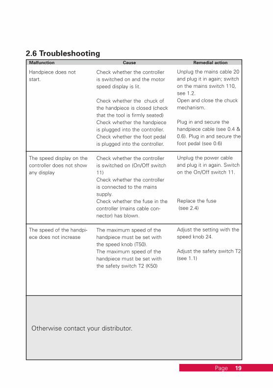
Otherwise contact your distributor.
Malfunction Cause Remedial action
Handpiece does not start.
The speed display on the controller does not show any display
The speed of the handpi-ece does not increase
Check whether the controller is switched on and the motor speed display is lit.
Check whether the chuck of the handpiece is closed (check that the tool is firmly seated)Check whether the handpiece is plugged into the controller.Check whether the foot pedal is plugged into the controller.
Check whether the controller is switched on (On/Off switch 11)Check whether the controller is connected to the mains supply.Check whether the fuse in the controller (mains cable con-nector) has blown.
The maximum speed of the handpiece must be set with the speed knob (T50).The maximum speed of the handpiece must be set with the safety switch T2 (K50)
Unplug the mains cable 20 and plug it in again; switch on the mains switch 110, see 1.2.Open and close the chuck mechanism.
Plug in and secure the handpiece cable (see 0.4 & 0.6). Plug in and secure the foot pedal (see 0.6)
Unplug the power cable and plug it in again. Switch on the On/Off switch 11.
Replace the fuse (see 2.4)
Adjust the setting with the speed knob 24.
Adjust the safety switch T2 (see 1.1)
2.6 Troubleshooting
Page

3.
20 20
3.2 Scope of delivery VARIOstar K50:Knee control unit VARIOstar K50 230V 804-3012Knee control unit VARIOstar K50 115V 804-3011Table mount 896-1022 Fixing knob 896-1023Assembly diagram 896-1024 Power cord 896-1020Operation Manual
Data
Page
3.1 Technical Data:Dimensions: VARIOstar K50 VARIOstar T50Control unitWidth 95mm 180mmHeight 250mm 140mmDepth 310mm 200mmWeight 5,6kg 7,1kgRated voltage AC 230V/115V AC 230V/115VRated frequency 50/60 Hz 50/60 HzPower consumption (max.) 270W 270WVARIOstar Handpiece VARIOstarSpeed range 1.000- 50.000/minMax. Torque max. 7,8NcmProtection class ILength 162mmDiameter 30mmWeight 235g

804-1016 804-1015 804-1017
2121
3.4 Poduct overview VARIOstar and spare parts:Handpiece VARIOstar with Chuck Ø2,35mm only 804-3002Handpiece VARIOstar with Chuck Ø3,00mm only 804-3005Handpiece Stand standard 896-1019Handpiece Stand with digital speed display K50 896-1021Tip 896-1001O-ring for tip 896-1002Spindle, completely assembled 896-1003Chuck, 2.35 mm 896-1004Protection pin, 2.35 mm 896-1005Chuck, 3.00 mm 896-1006Protection, pin 3.00 mm 896-1007Ring, red 896-1015Motor cable 896-1016Flat spanner, tool 1 896-1017Chuck holder, tool 2 896-1018
3.3 Scope of delivery VARIOstar T50:Tabletop control unit VARIOstar T50 230V 804-3052Tabletop control unit VARIOstar T50 115V 804-3051VARIO Foot Pedal, standard 804-1016VARIO Rotary Foot Lever 804-1015VARIO Knee Pedal (can be mounted left or right) 804-1017Power cord 896-1020Operation Manual
Page

K50
4.
22 22
Safety notesEven if you barely remove any material and cannot see dust particles, milling and grinding generates fine dust that is sus-pended in the air throughout the entire room. The distance between your face and the grinding position is so small that you inhale high concentrations of this dust, even if you consider the grinding amount to be insignificant. The fine com-ponents of the dust in particular penetra-te deeply into the lungs with ease. Alveolar dust particles with a size of less than 5 µm can settle in the lungs and lead to permanent asthmatic suffering and serious lung diseases.
Remember, it’s your job. You are exposed to this contamination every day!
Dust in dental technology – a great danger!Dental technicians are especially endangered. According to statistics held by the employer’s liability insurance association, occupationally-related skin and lung diseases are considerably higher here than the average in the industries united in the employer’s liability insurance association for fine mechanics and electrical engineering.
Fine dust in the air is particularly dangerous. Damaging effects on the skin and the respiratory organs have also been found with dental gypsum, embedding compounds and unclassified mixed dusts that are assigned to the general dust limit values.
The Ordinance on Hazardous Substances principally prescribes the extraction of dusts as a legal requirement.
An optimization of the intake systems and the use of modern dust collectors can decrease the dust concentration many times over.
Zubler offers a dust collection solution to suit laboratories of all sizes.
Page

5.
2323
In accordance with its General Terms and Conditions of Business, Zubler Gerätebau GmbH (Zubler) guarantees the perfect function of the equip-ment and its freedom from material and manufacturing defects for a peri-od of 12 months from the date of purchase certified by the seller.
We give a lifetime guarantee on armature and winding.
In case of valid complaints, from the armature and winding Zubler provides replacement parts or repairs free of charge.
The warranty does not cover defects and their consequences if they are caused or could have been caused by: natural wear and tear; inappropriate treatment, cleaning or maintenance; disregard of the maintenance, opera-ting or connection instructions; corrosion; contamination; chemical or electrical effects that are unusual or impermissible.
The warranty claim will not be accepted if defects or their consequences are due to interference with or modifications to the product. Warranty claims can only be asserted if they are notified without delay to Zubler in writing. A copy of the invoice or delivery note is to be attached to the notification.
In addition to the guarantee, the purchaser’s legal warranty claims apply, wherein the warranty period is 12 months.
Warranty terms
Page
Service

Zubler Gerätebau GmbHBuchbrunnenweg 26D-89081 Ulm-Jungingen
www.zubler.de
®
dental & technik
en M-V
AR
IOst
ar 3
6/20
18en
tech
nisc
he Ä
nder
unge
n vo
rbeh
alte
n!


