35
Various surface processing of cables against RWIV Olivier FLAMAND – CSTB – Nantes - FRANCE

Various surface processing of cables against RWIVOlivier FLAMAND – CSTB – Nantes - FRANCE
1 Introduction
prevention against RWIV + drag reduction
2 Surface indentation : the Japanese way
how the surface indented cables for the Tatarabridge were designed
3 Spiraled wires
how the helical rib sheath for the Normandiebridge was designed
4 Following studies
how the helical rib sheath was improved for bigger diameter
5 Recent development
what should we do now
6 Conclusion
Pres
enta
tion
Plan

Cable stayed bridges : Ever longer spans
1986 : Annacis 465 m1995 : Normandie 856 m1999 : Tatara 890 m
2007 : Stonecutters 1018 m2008 : Sutong 1088 m

EvenEven if if thesethesebridges are bridges are
«« cablecable stayedstayed »»
The stays are generally not highlighted
Low technical content ?

When length of cables increases, their excitability increases too.
A survey on japanese bridges, after Yamada
Because frequencies and damping are lower

The balance of drag The balance of drag force for a 900m spanforce for a 900m span
the deck
the cables
the pylon
35%
15%
50%
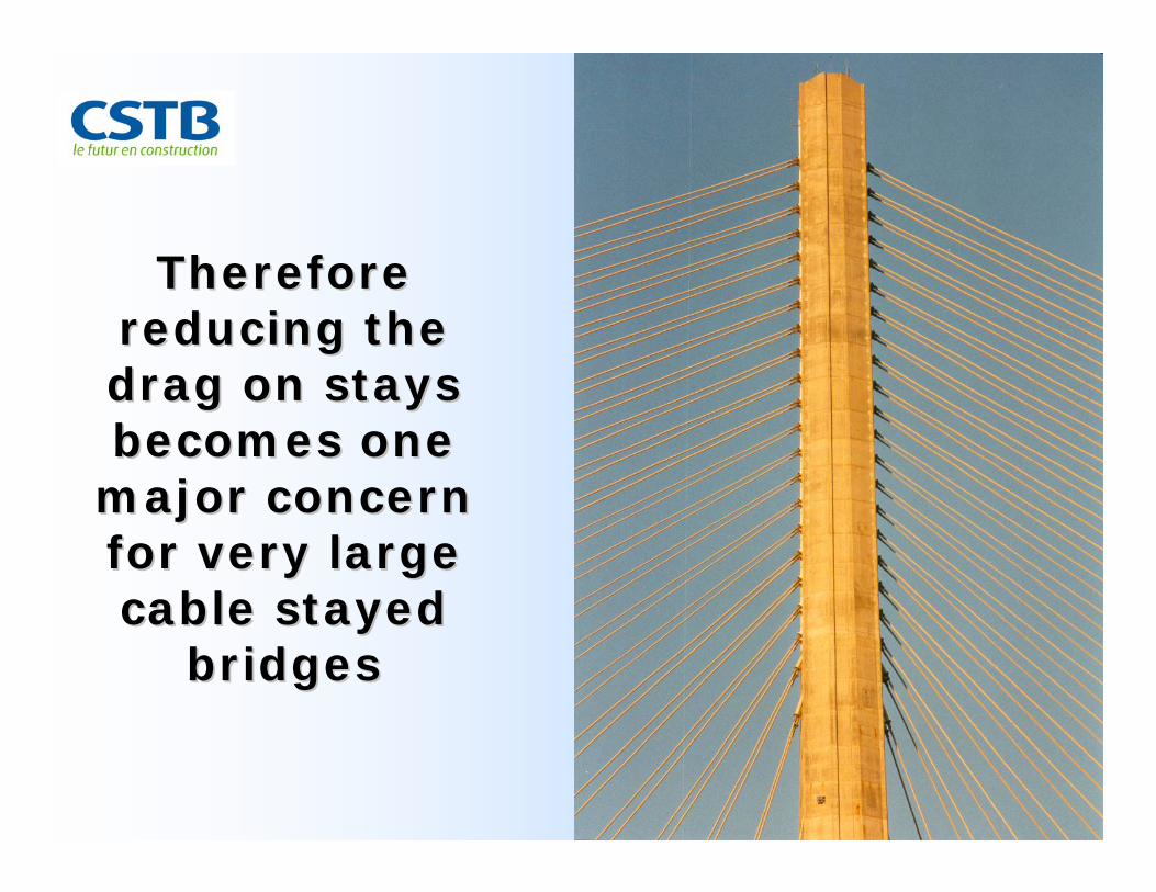
Therefore Therefore reducing the reducing the drag on stays drag on stays becomes one becomes one
major concern major concern for very large for very large cable stayed cable stayed
bridgesbridges

When designing the cable system, When designing the cable system, one can act on size and shapeone can act on size and shape

Why does the best shape, from the Why does the best shape, from the aerodynamic point of view, usually aerodynamic point of view, usually
be the circular cylinder ?be the circular cylinder ?
Wind tunnel tests for the Normandie Bridge
Because it is symmetrical :
Smaller risk of galloping
No drag force change with wind direction
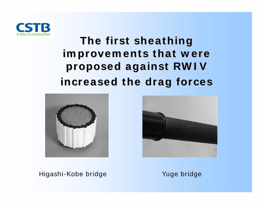
The first sheathing The first sheathing improvements that were improvements that were proposed against RWIV proposed against RWIV
increased the drag forcesincreased the drag forces
Higashi-Kobe bridge Yuge bridge

Surface indentation : the Surface indentation : the JapaneseJapanese wayway
The initial idea came from aerodynamicists :
• The shark-skin principle : reducing the forcesby a surface processing
• The drag force crisis on circular cylinders can be attainedwith lower wind speed

Drag crisis is well Drag crisis is well documented for cylinders documented for cylinders
and other shapesand other shapes
After FAGE A. and WARSAP J.H. - 1930

Drag crisis for cylinders depends Drag crisis for cylinders depends on the roughness of the surfaceon the roughness of the surface
2 105
4 105
Re
Increasing the roughness, one can trigger the occurrence of supercritical Cd at lower wind speed
0.70
0.90But the drag force increases too
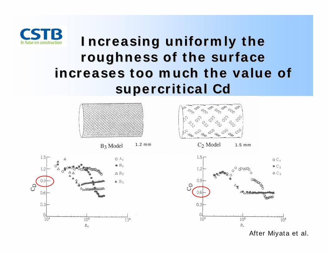
Increasing uniformly the Increasing uniformly the roughness of the surface roughness of the surface
increases too much the value of increases too much the value of supercritical supercritical CdCd
1.2 mm 1.5 mm
After Miyata et al.
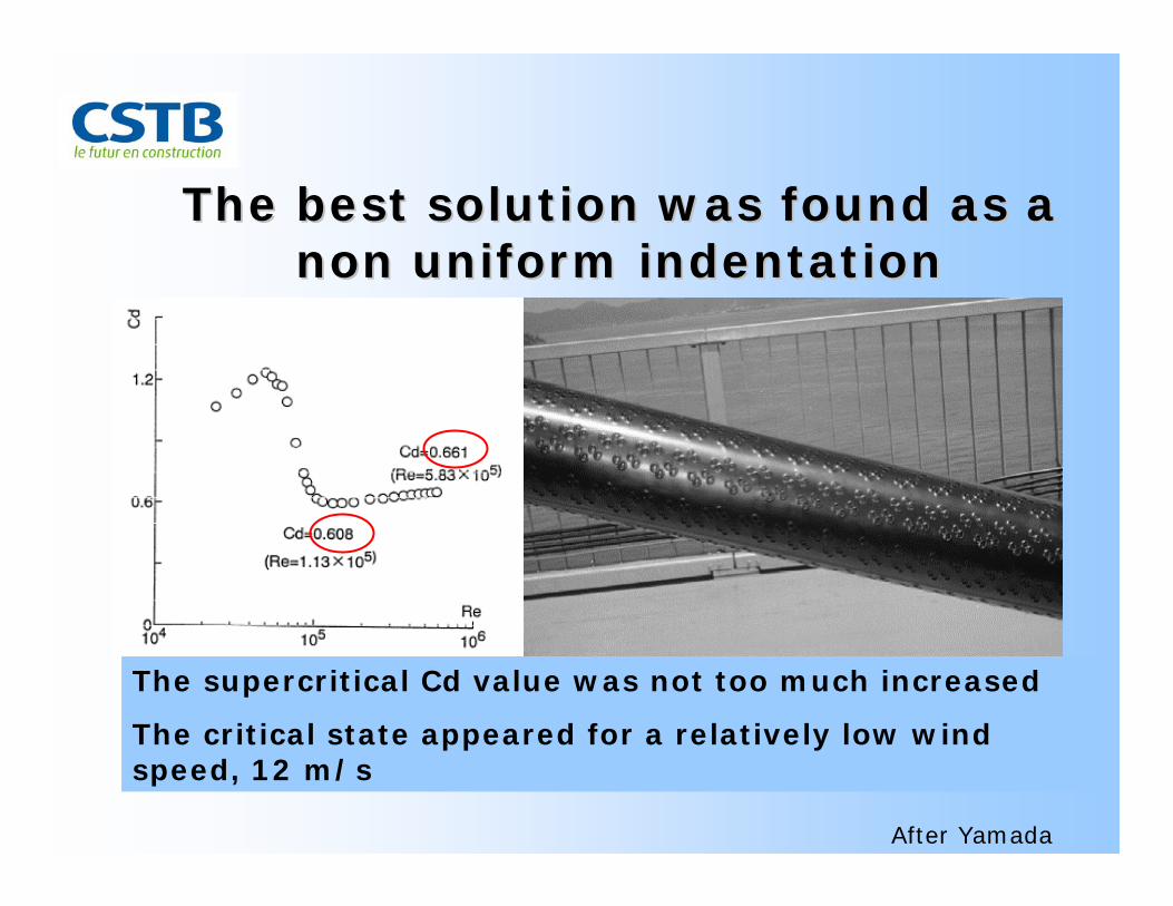
The best solution The best solution waswas foundfound as a as a non non uniformuniform indentationindentation
The supercritical Cd value was not too much increased
The critical state appeared for a relatively low wind speed, 12 m/s
After Yamada

SpiraledSpiraled wireswires
The initial idea came from experience :
• Another 2 dimensions excitation, the vortex shedding,
is easily suppressed when the birth of vortexes is
decorrelated along the line like structure.
• Spirals are commonly used on cylinders for this purpose

The helical strakes are used on The helical strakes are used on stacks, submarine risers, …stacks, submarine risers, …
However, they do increase the drag forces

The idea was to design a circular The idea was to design a circular sheathing with a minimum strakesheathing with a minimum strake
Parameters :
•Wire diameter
•Helical step
•Wire shape

This design was made for the This design was made for the stays of the stays of the NormandieNormandie bridgebridge
•Wire diameter
•Helical step
•Wire shape
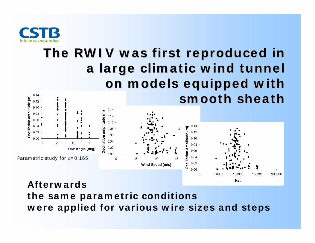
The RWIV was first reproduced in The RWIV was first reproduced in a large climatic wind tunnela large climatic wind tunnel
on models equipped withon models equipped withsmooth sheathsmooth sheath
Afterwards the same parametric conditionswere applied for various wire sizes and steps
Parametric study for φ=0.165


As it was proved to be efficient, As it was proved to be efficient, the wire size was optimized to the wire size was optimized to yield the smallest drag force, yield the smallest drag force,
CxCx=0.62=0.62

Normandie bridgeTatara bridge
Ten years ago we had two Ten years ago we had two solutions at our disposalsolutions at our disposal
Why was only one of both widely used afterwards ?

Following studies : the same Following studies : the same kind of tests with greater sizekind of tests with greater size
Every time a sheathing was tested, the thickness of the rib was reduced with great care, step by step, to attain the minimum still efficient against RWIV.

The sheathing were tested The sheathing were tested against RWIVagainst RWIV
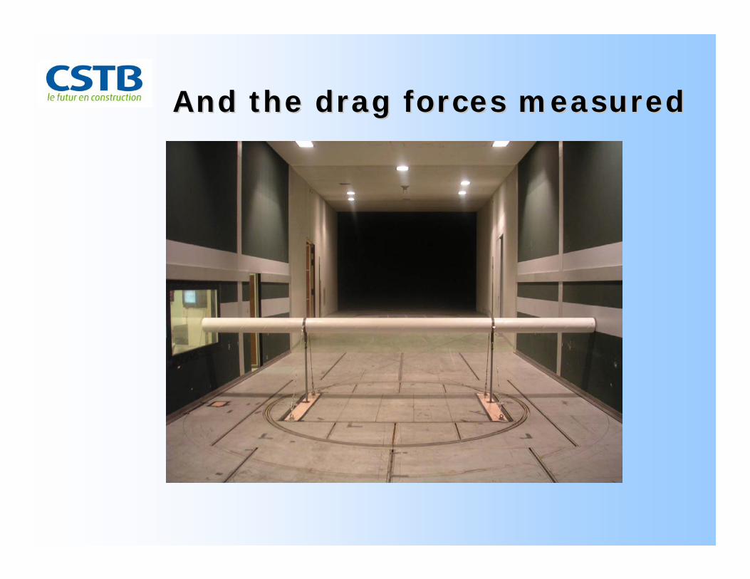
And the drag forces measuredAnd the drag forces measured

The results for smooth sheathing The results for smooth sheathing showed an evolution in the RWIV showed an evolution in the RWIV intensity with increasing diameterintensity with increasing diameter
180 mm diam, smooth pipe, α=20°
-0,6
-0,5
-0,4
-0,3
-0,2
-0,1
00 5 10 15 20
wind speed (m/s)
dam
ping
/ cr
itica
l (%
) β = 20°
β = 30°
β =35°
β = 40°
β = 50°
225 mm diam, smooth pipe, α=20°
-0,2
-0,15
-0,1
-0,05
00 5 10 15 20
wind speed (m/s)
dam
ping
/crit
ical
(%)
β = 20°β = 30°
180 mm diam, smooth pipe, α=30°
-0,6
-0,5
-0,4
-0,3
-0,2
-0,1
00 5 10 15 20
wind speed (m/s)
dam
ping
/ cr
itica
l (%
)
β = 20°
225 mm diam, smooth pipe, α=30°
-0,2
-0,15
-0,1
-0,05
00 5 10 15 20
wind speed (m/s)
dam
ping
/crit
ical
(%)
β = 10°β = 15°β = 30°

With the same conditions the With the same conditions the sheathing with a double helical rib sheathing with a double helical rib stayed stable at any tested speed.stayed stable at any tested speed.
180 mm diameter pipe with helical thread, α=30°
0
0,1
0,2
0,3
0,4
0,5
0 5 10 15 20U (m/s)
dam
ping
(% o
f crit
ical
)
β=10°
β=20°
β=30°
mech. 0.05%

The change in drag force with The change in drag force with diameter was noticeable toodiameter was noticeable too
Drag coefficient Cx for the 160mm diameter sheath
0,55
0,57
0,59
0,61
0,63
0,65
0,67
0,0 20,0 40,0 60,0 80,0
wind speed (m/s)
Cx
coef
ficie
nt
Drag coefficient Cx for the 200mm diameter sheath
0,55
0,57
0,59
0,61
0,63
0,65
0,67
0,0 20,0 40,0 60,0 80,0
wind speed (m/s)
Cx
coef
ficie
nt
Drag coefficient for the 225 mm diameter sheath
0,55
0,57
0,59
0,61
0,63
0,65
0,67
0,0 20,0 40,0 60,0 80,0
Wind speed (m/s)
Cx
coef
ficie
nt
Drag coefficient for the 250 mm diameter sheath
0,55
0,57
0,59
0,61
0,63
0,65
0,67
0,0 20,0 40,0 60,0 80,0
Wind speed (m/s)
Cx
coef
ficie
nt
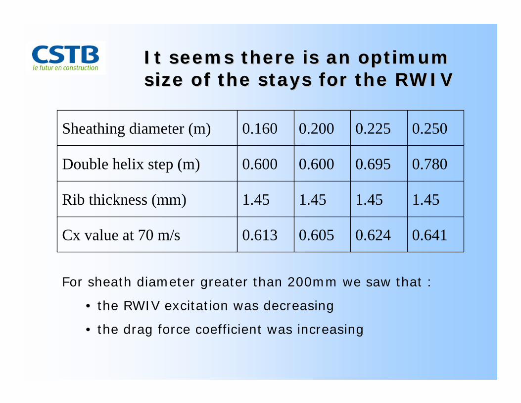
It seems there is an optimum It seems there is an optimum size of the stays for the RWIVsize of the stays for the RWIV
0.6410.6240.6050.613Cx value at 70 m/s
1.451.451.451.45Rib thickness (mm)
0.7800.6950.6000.600Double helix step (m)
0.2500.2250.2000.160Sheathing diameter (m)
For sheath diameter greater than 200mm we saw that :
• the RWIV excitation was decreasing
• the drag force coefficient was increasing

Recent developmentRecent developmentThe monitoring of more and more in service bridges may yield very useful information, if measurements are made with care.
Minimum requirement : wind speed and direction, 3dof disp. of deck, 2 dof disp. of pylon, 2dof dip. of various cables.

Efficiency of sheath ?Efficiency of sheath ?
Few occurrences of vibrations of cables equipped with double helical ribs were reported.
• Parametric excitation from deck or pylon?
• Dry cable galloping ?
• 3D vortex shedding ?
• Icing ?
Does it mean the sheaths designed against RWIV are not efficientagainst other potential sources of excitation ?
Does it mean the sheaths were not carefully designed with respect to the pitch of the rib?

Another approachAnother approach
In any case, consider the stay is not responsible for the vibration,
but the stay is dissipating, though its vibration, the energy contained in the whole bridge structure.
The effect of any of the aerodynamic instabilities
•galloping
•vortex shedding
• RWIV…
is only to reduce the aerodynamic damping of the cables.

Research topicsResearch topics
Research is now focused on the modeling of the upper rivulet.
The next step will be to model the aerodynamic damping of the stays, with respect to the outer conditions
Wind speed and direction, rain, ice, roughness and water repellancy of the surface…
Finally, include these model of damping of cables, with models of damping for the deck and the pylons, in a whole bridge calculation, compare it with monitoring data.

For the new generation of very long cable stayed bridges (span >1000 m)
Conclusion
• Careful design of the sheathing with regard to drag forces and efficiency against RWIV
• Design of the bridge as a whole, cables-deck-pylon, taking into account the aerodynamic damping of each part
• Provide additional structural damping


