92
VariStep3 – Stepper Motor Driver Operating Manual P/N 01.50.020 – EN | Rev. 08/2018

VariStep3 – Stepper Motor Driver
Operating Manual
P/N 01.50.020 – EN | Rev. 08/2018

Original instructions
Copyright © Copyright 2018 MOTORTECH GmbH. All rights reserved.
Distribution and reproduction of this publication or parts thereof, regardless of the specific purpose and form, are not permissible without express written approval by MOTORTECH. Information contained in this publication may be changed without prior notice.
Trademarks MOTORTECH products and the MOTORTECH logo are registered and/or common law trademarks of the MOTORTECH Holding GmbH. All further trademarks and logos displayed or used in this publication are the property of the respective entitled person.

Rev. 08/2018 3
1 General Information .................................................................................................... 6 1.1 What Is the Purpose of this Operating Manual? ......................................................... 6 1.2 Who Is this Operating Manual Targeted to? ............................................................... 6 1.3 Which Symbols Are Used in the Operating Manual? ................................................... 6 1.4 Which Abbreviations/Acronyms Are Used in the Operating Manual? ........................... 7
2 Safety Instructions ..................................................................................................... 8 2.1 General Safety Instructions ..................................................................................... 8 2.2 Electrostatic Discharge Hazards .............................................................................. 9 2.3 Information on Electric Isolation .............................................................................. 9 2.4 Special Safety Instructions for the Device .............................................................. 10 2.5 Proper Disposal .................................................................................................... 12
3 Intended Use ............................................................................................................. 13 3.1 Functional Description .......................................................................................... 13 3.2 Applications ......................................................................................................... 13
4 Product Description ................................................................................................... 15 4.1 Technical Data ...................................................................................................... 15 4.1.1 Certifications ..................................................................................................... 15 4.1.2 Mechanical Data ................................................................................................ 17 4.1.3 Warning Notices on the Device ............................................................................ 17 4.1.4 Product Identification – Labeling on the Device .................................................... 18 4.1.5 Electrical Data .................................................................................................... 19 4.1.6 Interfaces .......................................................................................................... 20 4.1.7 Overview Drawings ............................................................................................. 21
5 Installation Instructions ............................................................................................. 24 5.1 Installation Instructions ........................................................................................ 24
6 Wiring of the Device ................................................................................................... 25 6.1 Wiring Power Supply ............................................................................................. 27 6.2 Wiring Stepper Motor and Encoder ........................................................................ 28 6.3 Wiring Binary Inputs ............................................................................................. 30 6.4 Wiring Binary Outputs........................................................................................... 31 6.5 Wiring Analog Inputs and Outputs ......................................................................... 32 6.6 Wiring CAN Bus .................................................................................................... 33 6.7 Wiring Modbus ..................................................................................................... 34
7 Functions ...................................................................................................................36 7.1 Manual and Automatic Operation ........................................................................... 36
Table of Contents

Table of Contents
4 Rev. 08/2018
7.2 Reference Run ...................................................................................................... 36 7.3 Open/Closed Positions ......................................................................................... 37 7.4 Configurable Opening Angles (Position 1 and 2) ...................................................... 37 7.5 Change of Opening Angles via Binary and Analog Inputs ......................................... 37 7.6 Analysis of Positions via Analog Outputs or Field Bus ............................................. 38 7.7 Access Control ...................................................................................................... 38
8 Settings via the MICT ................................................................................................. 40 8.1 MICT System Requirements ................................................................................... 40 8.2 MICT Installation .................................................................................................. 40 8.3 Access Levels in the MICT ..................................................................................... 41 8.4 Configuration Pages (Overview) ............................................................................ 42 8.5 Menu Bar and Toolbar........................................................................................... 43 8.6 Online Update Settings ........................................................................................ 46 8.7 Access Control of the Stepper Motor Driver ............................................................ 47 8.7.1 Enable/Disable Access Control ........................................................................... 47 8.7.2 Login/Logout .................................................................................................... 47 8.7.3 Changing the PIN ............................................................................................... 48 8.7.4 Reset all PINs .................................................................................................... 48 8.8 Working with Configurations ................................................................................. 49 8.8.1 Create, Open, Save ............................................................................................ 50 8.8.2 Upload, Download ..............................................................................................51 8.8.3 Compatibility Information ...................................................................................51 8.9 Configuration ....................................................................................................... 52 8.9.1 External Device .................................................................................................. 53 8.9.2 Inputs/Outputs – Control Setup ......................................................................... 56 8.9.3 Positions – Values ............................................................................................. 59 8.9.4 Miscellaneous – Communication ........................................................................ 60 8.9.5 Miscellaneous – Service Contact ........................................................................ 62 8.10 Runtime Data ..................................................................................................... 63 8.10.1 Runtime Data – Overview .................................................................................. 64 8.10.2 Runtime Data – Message Log ............................................................................ 66 8.10.2.1 Information ................................................................................................... 67 8.10.2.2 Warnings ...................................................................................................... 67 8.10.2.3 Errors ........................................................................................................... 68 8.10.3 Runtime Data – Diagnostics .............................................................................. 69 8.10.4 Runtime Data – Information ............................................................................... 71 8.11 Log ...................................................................................................................... 71

Table of Contents
Rev. 08/2018 5
9 Operation .................................................................................................................. 73 9.1 Firmware Update................................................................................................... 73
10 Errors ....................................................................................................................... 77 10.1 Troubleshooting .................................................................................................. 77 10.2 Possible Faults ................................................................................................... 78 10.3 Acknowledging Faults ......................................................................................... 79 10.4 Customer Service Information .............................................................................. 79 10.5 Returning Equipment for Repair/Inspection .......................................................... 80 10.6 Instructions for Packaging the Equipment ............................................................ 80
11 Maintenance ............................................................................................................. 81 11.1 Spare Parts and Accessories ................................................................................. 81
12 Annex ..................................................................................................................... 82 12.1 Replacement of the Stepper Motor Driver .............................................................. 82 12.1.1 VariStep to VariStep3 Stepper Motor Driver ........................................................ 82 12.1.2 VariFuel2 to VariStep3 Stepper Motor Driver....................................................... 85
13 Index ....................................................................................................................... 89

6 Rev. 08/2018
Read through this operating manual carefully before use and become familiar with the product. Installation and start-up should not be carried out before reading and understanding this document. Keep this manual readily available so that you can reference it as needed.
1.1 What Is the Purpose of this Operating Manual? This manual serves as an aid for the installation and operation of the product and supports the technical staff with all operating and maintenance tasks to be performed. Furthermore, this manual is aimed at preventing dangers to life and health of the user and third parties.
1.2 Who Is this Operating Manual Targeted to? The operating manual provides a code of conduct for personnel tasked with the setup, operation, maintenance, and repair of gas engines. A certain level of technical knowledge with respect to the operation of gas engines and basic knowledge of electronic ignition systems are necessary. Persons who are only authorized to operate the gas engine shall be trained by the operating company and shall be expressly instructed concerning potential hazards.
1.3 Which Symbols Are Used in the Operating Manual? The following symbols are used in this manual and must be observed:
Example
This symbol indicates examples, which point out necessary handling steps and techniques. In addition, you receive additional information from the examples, which will increase your knowledge.
Notice
This symbol indicates important notices for the user. Follow these. In addition, this symbol is used for overviews that give you a summary of the necessary work steps.
Warning
This symbol indicates warnings for possible risks of property damage or risks to health. Read these warning notices carefully and take the mentioned precautionary measures.
1 General Information

1 General Information
Rev. 08/2018 7
Danger
This symbol indicates warnings for danger to life, especially due to high voltage. Read these warning notices carefully and take the mentioned precautionary measures.
1.4 Which Abbreviations/Acronyms Are Used in the Operating Manual? In the manual or the user interface, the following abbreviations / acronyms are used.
Abb. Term Description Explanation
CAN bus Controller Area Network bus
Bus for control devices / networks
Asynchronous serial connection system for linking control units
CE Conformité Européenne
Conformity with EU directives
Mark based on EU legislation for certain products in conjunction with product safety
CPU Central Processing Unit
Central processing unit
DC Direct Current Direct current
EMC Electromagnetic Compatibility
Compatibility of electrical or electronic equipment items with their surroundings
ESD Electrostatic Discharge
Electrostatic discharge
ITB Integrated Throttle Body
Throttle with integrated stepper motor
LED Light Emitting Diode Light emitting diode Light emitting electronic semiconductor
MICT MOTORTECH Integrated Configuration Tool
Configuration software for MOTORTECH control units
TG Throttle Gear Throttle drive
USB Universal Serial Bus Serial connection system to link a computer to external devices
8 Rev. 08/2018
2.1 General Safety Instructions MOTORTECH equipment is manufactured as state of the art and therefore safe and reliable to operate. Nevertheless the equipment can cause risks or damage can occur, if the following instructions are not complied with:
– The gas engine must only be operated by trained and authorized personnel.
– Operate the equipment only within the parameters specified in the technical data.
– Use the equipment correctly and for its intended use only.
– Never apply force.
– For all work such as installation, conversion, adaptation, maintenance, and repair, all equipment must be disconnected from the mains and secured against unintentional reactivation.
– Perform only such maintenance and repair work as is described in this operating manual, and follow the instructions given while working.
– For maintenance of the equipment, only use spare parts supplied by MOTORTECH.
– Further work must only be performed by personnel authorized by MOTORTECH. Non-compliance with the instructions will void any warranties for the proper function of the equipment as well as the responsibility for the validity of the certifications.
– Safety devices must not be dismounted or disabled.
– Avoid all activities that can impair the function of the equipment.
– Operate the equipment only while it is in proper condition.
– Investigate all changes detected while operating the gas engine or ignition system.
– Ensure compliance with all laws, directives and regulations applicable to the operation of your system, including such not expressly stated herein.
– If the system is not entirely tight and sealed, gas may escape and result in explosion hazard. The inhalation of gas can also lead to death or severe health damages. Therefore, upon completion of all assembly works, always check the system's tightness.
– Always ensure adequate ventilation of the engine compartment.
– Ensure a safe position at the gas engine.
– There is a risk of burning on hot surfaces. Allow the engine to cool down before starting work.
– Personal protective equipment (PPE), e.g. safety shoes and gloves, must be worn during all work on the engine.
– Your behavior can reduce possible residual risks to a minimum. Ensure responsible handling of the engine.
2 Safety Instructions

2 Safety Instructions
Rev. 08/2018 9
2.2 Electrostatic Discharge Hazards Electronic equipment is sensitive to static electricity. To protect these components from damage caused by static electricity, special precautions must be taken to minimize or prevent electrostatic discharge.
Observe these safety precautions while you work with the equipment or in its vicinity.
– Before performing maintenance or repair work, ensure that the static electricity inherent to your body is discharged.
– Do not wear clothing made from synthetic materials to prevent static electricity from building up. Your clothing should therefore be made of cotton or cotton mix materials.
– Keep plastics such as vinyl and Styrofoam materials as far away from the control system, the modules, and the work environment as possible.
– Do not remove the circuit boards from the housing of the device.
2.3 Information on Electric Isolation If ground and earth potential are not properly isolated, the following problems as well as others can occur:
– Electromagnetic interferences (e.g. ground loops)
– Signal corruption (e.g. of the analog voltage signal)
– Unwanted leakage currents
Therefore, earth potential and the negative pole of the power supply of all devices in the electric assembly that provide the option, should be connected separately. If possible, the negative pole of the power supply should only be connected to earth potential at one point in the entire system.
Wiring Example Device with
shielded wires Device featuring protection class II

2 Safety Instructions
10 Rev. 08/2018
Occurrence of ground loops
The devices shown in the following image do not feature the possibility to connect the earth potential and the negative pole of the power supply separated from each other. How ground loops are created.
A ground loop is a ground connection of an electric wiring assembly that is closed as a loop. Due to impedance (resistance R > ) of the loop, low-frequency interference currents can lead to an unwanted voltage drop in the signal path.
Device 1 Device 2
Ground loop
2.4 Special Safety Instructions for the Device
Gas! Danger to life!
Leaking gas may cause death or serious health damage if inhaled. Upon completion of all assembly works, always check the system's tightness. When operating a VariFuel2, make sure that the gauge ports are closed.
All works involving gas-carrying parts must be executed by trained personnel only.

2 Safety Instructions
Rev. 08/2018 11
Explosion hazard!
If the system is not entirely tight and sealed, gas may escape and result in explosion hazard. Upon completion of all assembly works, always check the system's tightness. The formation of explosive gases in the area of the device must be prevented, e.g. by adequate ventilation or the use of gas sensors which switch off the gas supply.
All works involving gas-carrying parts must be executed by trained personnel only.
Explosion hazard!
Do not disconnect any connectors while the system is live. If the system is located in a hazardous area, there is a risk of explosion.
Operational safety!
All screws of the connectors must be adequately tightened.
Risk of destruction due to electrostatic discharge!
The VariStep3 stepper motor driver may only be installed by specialized personnel who has been trained in handling ESD sensitive components and with due regard to relevant ESD standards. It must be installed into a control cabinet, and it must comply with the ESD standard DIN EN 61340-5-1; VDE 0300-5-1:2008-07.
Damage caused by electrostatic discharge is not covered by warranty.
Risk of burning!
The surfaces of the system may heat up to high temperatures. Ensure good heat transfer through ventilation when installing in the control cabinet.

2 Safety Instructions
12 Rev. 08/2018
2.5 Proper Disposal After the expiration of its service life, MOTORTECH equipment can be disposed of with other commercial waste, or it may be returned to MOTORTECH. We will ensure its environmentally friendly disposal.
Rev. 08/2018 13
3.1 Functional Description The VariStep3 stepper motor driver drives the stepper motor of a gas mixer or throttle. This stepper motor carries out position changes:
– The stepper motor adjusts the openings for the gas supply of the gas mixer and thereby alters the composition of the gas-air mix.
– In the throttles the stepper motor changes the opening angle of the throttle and thereby controls the supply of the gas-air mix.
Control can be manual or automatic. Manual adjustments can be made using buttons on the stepper motor driver via a connected PC. In automatic mode, binary or analog input signals, such as those provided by a master control, are analyzed. In addition, a connection via CAN bus and Modbus is possible.
The stepper motor driver is configured using a connected PC. The software used for this purpose is also used to display current system data and error messages.
3.2 Applications The VariStep3 stepper motor driver can be used for the following MOTORTECH devices:
– Gas mixer with stepper motor (e.g. VariFuel2)
– ITB throttles with integrated stepper motor
– TG throttle drives
If several devices which are to be controlled via the VariStep3 stepper motor driver are to be used in one system, several stepper motor drivers are needed. An additional splitter is not necessary.
Any use other than the one described in the operating manual shall be considered improper use and will result in the voiding of all warranties.
3 Intended Use

3 Intended Use
14 Rev. 08/2018
System Overview (Example)
VariStep3 stepper motor drivers Engine
VariFuel2 gas mixer Wiring rail (ignition)
ITB throttle with integrated stepper motor Gas supply
SC100 speed control Gas train
Air supply
Air filter

Rev. 08/2018 15
4.1 Technical Data
4.1.1 Certifications The stepper motor driver is certified in accordance with the following standards:
CE – EMC Directive
– EN 61000-6-1:2007 – Electromagnetic compatibility (EMC). Generic standards; Immunity for residential, commercial and light-industrial environments
– EN 61000-6-2:2005 + AC:2005 – Electromagnetic compatibility (EMC). Generic standards. Immunity for industrial environments
– EN 61000-6-3:2007 + A1:2011 – Electromagnetic compatibility (EMC). Generic standards. Emission standard for residential, commercial and light-industrial environments
– EN 61000-6-4:2007 + A1:2011 – Electromagnetic compatibility (EMC). Generic standards. Emission standard for industrial environments
– EN 55011:2009 + A1:2010 – Industrial, scientific and medical equipment. Radio-frequency disturbance characteristics. Limits and methods of measurement
4 Product Description
4 Product Description
16 Rev. 08/2018
4 Product Description
Rev. 08/2018 17
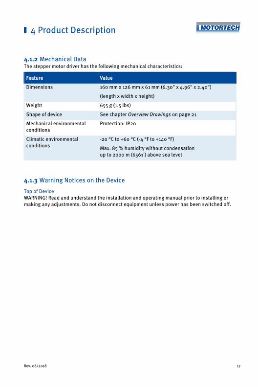
4.1.2 Mechanical Data The stepper motor driver has the following mechanical characteristics:
Feature Value
Dimensions 160 mm x 126 mm x 61 mm (6.30" x 4.96" x 2.40")
(length x width x height)
Weight 655 g (1.5 lbs)
Shape of device See chapter Overview Drawings on page 21
Mechanical environmental conditions
Protection: IP20
Climatic environmental conditions
-20 °C to +60 °C (-4 °F to +140 °F)
Max. 85 % humidity without condensation up to 2000 m (6561') above sea level
4.1.3 Warning Notices on the Device Top of Device WARNING! Read and understand the installation and operating manual prior to installing or making any adjustments. Do not disconnect equipment unless power has been switched off.

4 Product Description
18 Rev. 08/2018
4.1.4 Product Identification – Labeling on the Device The numbers required for unique product identification are on the device:
Top of Device
Abb. Meaning
P/N Part number of the stepper motor driver
S/N Serial number of the stepper motor driver
A/N Arrangement number of the stepper motor driver
R/N Revision number of the stepper motor driver

4 Product Description
Rev. 08/2018 19
4.1.5 Electrical Data The stepper motor driver has the following electrical characteristics:
Feature Value
Power consumption max. 60 W
Power supply Nominal voltage: 24 V DC Operating voltage: 18 V DC to 32 V DC
Required current max. 5.0 A
Electrical Data for Inputs and Outputs The inputs and outputs of the stepper motor driver have the following electrical data:
Inputs and outputs Values/characteristics
Binary inputs – Galvanically isolated
– Input voltage up to 32 V DC
– Input current at least 5 mA for high level
– Save low level: Voltages below 1.0 V DC for at least 70 μs
– Save high level: Voltages above 4.5 V DC for at least 5 μs
Diagram of the Signal
When the reset signal is given, the high level must be present at the relevant input for at least 50 ms before it is possible to initiate the reset.

4 Product Description
20 Rev. 08/2018
Inputs and outputs Values/characteristics
Binary outputs – Galvanically isolated
– Inactive: output is high-impedance
– Active: output is low-impedance
– Switching voltage: max. 32 V
– Current: max. 100 mA
– Max. voltage drop at 100 mA: 2.5 V
Analog voltage input Permissible voltage: 0 V to 10 V
Input resistance: 12.4 kΩ
Analog current input Permissible current: 0 mA to 20 mA
Max. difference in potential relative to device ground: +3.5 V
Input resistance: max. 25 Ω
Analog voltage output Output voltage: 0 V to 10 V
Working resistance: min. 500 Ω
Analog current output Output current: 0 mA to 20 mA
Working resistance: max. 500 Ω
4.1.6 Interfaces USB – Compatible with USB 1.1 and USB 2.0
– The connector type B is only suitable for temporary data exchange and not for a permanent connection.
CAN Bus 2.0B Interface – As per ISO 11898, up to 1 Mbit/s
– Transient-proof (automotive classification)
– Max. 110 participants
Modbus Interface – RS485 standard
– Max. 32 participants
– Full duplex (4-pole) or half duplex (2-pole)

4 Product Description
Rev. 08/2018 21
4.1.7 Overview Drawings Ports/Connections and LEDs
Designation Function
Binary Inputs Binary inputs that are used to change the position of the stepper motor. In addition, a binary input is available for a reset signal (see Wiring Binary Inputs on page 30).
Binary Outputs Binary outputs which signal the position of the stepper motor and the status of the stepper motor driver (see Wiring Binary Outputs on page 31).
Analog Inputs/Outputs
Analog inputs and outputs by use of which you can change and resend the position of the stepper motor (see Wiring Analog Inputs and Outputs on page 32).

4 Product Description
22 Rev. 08/2018
Designation Function
Manual/Auto (switch) Switch for changing between manual and automatic operation (see Manual and Automatic Operation on page 36)
Open/Close; Reset
In manual mode the stepper motor can be driven via the buttons Open and Close (see Manual and Automatic Operation on page 36). In the case of an error, the error can be reset followed by a reference run if you press the two buttons simultaneously.
The Open LED and the Close LED are flashing when the stepper motor is moved into the corresponding direction via the buttons. When a stop has been reached, the corresponding LED lights up permanently.
Status You can find details about status signaling in the following information box.
The LED flashes:
– green: The stepper motor driver is working properly.
– Orange: A warning occurred.
– red: An error occurred.
For additional information on warnings and errors, read section Runtime Data – Message Log on page 66.
Manual/Auto (LED) The LED lights up:
– green: The stepper motor driver is in automatic mode and is controlled by the master control.
– Orange: The stepper motor driver is in manual mode.
USB Port for data transmission to the PC. Data transmission is signaled by the LEDs blinking.
CAN Port for communication via CAN bus with master control. Data transmission is signaled by the LEDs blinking.
RS485 Port for communication via Modbus with superordinate control devices. Data transmission is signaled by the LEDs blinking.
Stepper Motor + Encoder
Port for the stepper motor and the encoder. LEDs A, B and I are flashing when the stepper motor is moving (see Wiring Stepper Motor and Encoder on page 28).
Power Connection for the supply voltage (see Wiring Power Supply on page 27). This LED lights up if the supply voltage is available.

4 Product Description
Rev. 08/2018 23
Status signaling
The status of the VariStep3 stepper motor driver is signaled via the LED Status.
– Flashing green: Error-free operation
– Flashing orange: Warning Warnings can be acknowledged by simultaneous pressing of buttons Open and Close (in manual Mode) or by the external reset signal. Warnings can for example be caused by:
– Overload of the device
In addition, the LED flashes orange for the following reasons.
– No device type has been configured (device type: None or Unknown).
– Device connected was changed.
– Overtemperature or over current error confirmed by MICT.
– A reference run is required.
The first two cases make downloading a modified configuration to the device a priority.
– Flashing red: Error Errors can be acknowledged by simultaneous pressing of buttons Open and Close or by the external reset signal. Errors can for example be caused by:
– Step loss
– Overtemperature
– Low voltage
– Over current
– Alternate flashing of red and green: The supply voltage for the device was too low during start up.
24 Rev. 08/2018
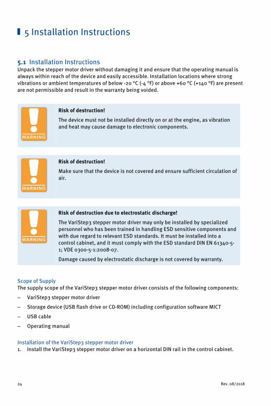
5.1 Installation Instructions Unpack the stepper motor driver without damaging it and ensure that the operating manual is always within reach of the device and easily accessible. Installation locations where strong vibrations or ambient temperatures of below -20 °C (-4 °F) or above +60 °C (+140 °F) are present are not permissible and result in the warranty being voided.
Risk of destruction!
The device must not be installed directly on or at the engine, as vibration and heat may cause damage to electronic components.
Risk of destruction!
Make sure that the device is not covered and ensure sufficient circulation of air.
Risk of destruction due to electrostatic discharge!
The VariStep3 stepper motor driver may only be installed by specialized personnel who has been trained in handling ESD sensitive components and with due regard to relevant ESD standards. It must be installed into a control cabinet, and it must comply with the ESD standard DIN EN 61340-5-1; VDE 0300-5-1:2008-07.
Damage caused by electrostatic discharge is not covered by warranty.
Scope of Supply The supply scope of the VariStep3 stepper motor driver consists of the following components:
– VariStep3 stepper motor driver
– Storage device (USB flash drive or CD-ROM) including configuration software MICT
– USB cable
– Operating manual
Installation of the VariStep3 stepper motor driver 1. Install the VariStep3 stepper motor driver on a horizontal DIN rail in the control cabinet.
5 Installation Instructions

Rev. 08/2018 25
Risk of damage to the device!
Incorrectly installed wiring can cause damage to the device. Please adhere to the following points:
– Do not disconnect connectors under load. This can cause an arc.
– Use the prescribed wire cross sections and suitable wire end ferrules.
Wiring of components
If you are not using wiring harnesses manufactured by MOTORTECH, carry out the wiring according to the following specifications:
– Power supply: 3-wire cable, min. conductor cross-section 0.75 mm², max. cable length 10 m (32') If the cable length is longer, a respective larger cross-section must be selected.
– Stepper motor: 4-wire, shielded cable, min. conductor cross-section 1.5 mm², max. cable length 30 m (98')
– Encoder: 5-wire, shielded cable, min. conductor cross-section 0.2 mm², max. cable length 30 m (98')
– Binary inputs and outputs: multicore cable, min. conductor cross-section 0.2 mm², max. cable length 30 m (98')
– Analog inputs and outputs: multicore, shielded cable, min. conductor cross-section 0.2 mm², max. cable length 30 m (98')
– CAN bus: 2-pair, shielded bus cable, min. conductor cross-section 0.34 mm², max. cable length 250 m (820')
– Modbus: 3-pair, shielded bus cable, min. conductor cross-section 0.25 mm², max. cable length 250 m (820')
6 Wiring of the Device

6 Wiring of the Device
26 Rev. 08/2018
Replacing VariStep and VariStep3
Pin assignment of connectors is identical for the VariStep and VariStep3 stepper motor drivers except for the connector Analog Inputs/Outputs. The identical plugs can simply be plugged from the old device into the new device. This also applies to CAN and Modbus (RS485) interfaces.
The socket for the stepper motor and encoder for the VariStep3 stepper motor driver has 12 poles. However, the 11-pole plug can still be used. It just needs to be plugged in at the far right. Pin 0 of the socket is currently not in use and therefore locked.
When changing the plug for the power supply, be aware that Earth and negative pole (–) must be connected separately on the VariStep3.

6 Wiring of the Device
Rev. 08/2018 27
6.1 Wiring Power Supply
Risk of injury!
The stepper motor may be started unintentionally when the supply voltage is applied. Especially if a throttle is connected, there is a risk of fingers or other body parts being trapped or squashed. Therefore, work on the connected devices (throttle or gas mixer) must always be carried out with disconnected supply voltage.
The power supply is wired using the 3-pole plug. In order to comply with the EMC requirements, it is absolutely necessary that the earth contact is connected with a wire separate from the negative pole (L -).
L≙ 18 V DC to 32 V DC (nominal voltage: 24 V DC)
Variations
1 Battery Generator Control Unit
2 Power supply
3 Battery Charger

6 Wiring of the Device
28 Rev. 08/2018
6.2 Wiring Stepper Motor and Encoder
Risk of destruction!
To rule out the possibility of moving the devices connected out of the control area, observe the following procedure when connecting the stepper motor to the VariStep3 stepper motor driver:
1. Configure the VariStep3 stepper motor driver for your device type (see section External Device on page 53.
2. Separate the stepper motor driver from the power supply.
3. Connect the stepper motor of the VariFuel2 air/gas mixer or the throttle to the stepper motor driver.
4. Connect the VariStep3 stepper motor driver again to the power supply.
▸ Now, the stepper motor driver will initiate a reference run. The device is ready for operation.
Assignment of the wire colors
Take the assignment of the wire colors of the wiring harness from the wiring diagram enclosed with the wiring harness.
Wiring via the 11-pole plug on the stepper motor driver. The socket for the stepper motor and encoder has 12 poles. The 11-pole plug must be plugged in at the far right. Pin 0 of the socket is currently not in use and therefore locked. The VariStep3 stepper motor driver has been approved for residential environments if the wiring of the stepper motor and encoder does have a length of no more than 10 m (32').

6 Wiring of the Device
Rev. 08/2018 29
Encoder
Stepper motor
Pin assignment when using the original MOTORTECH wiring harness:
Pin VariStep3 Designation Pin stepper motor and encoder
0 Encoder Data Currently not used
1 Encoder GND (Ground) J
2 Encoder Power (supply voltage) I
3 Encoder A E
4 Encoder B F
5 Encoder I (index) G
6 Encoder Shield H
7 Stepper Motor Phase B2 D
8 Stepper Motor Phase B1 C
9 Stepper Motor Shield H
10 Stepper Motor Phase A2 B
11 Stepper Motor Phase A1 A

6 Wiring of the Device
30 Rev. 08/2018
6.3 Wiring Binary Inputs The binary inputs are wired using the 10-pole plug. The inputs can be switched both on the side of the operating voltage and on the ground side.
L ≙ 5 V DC to 32 V DC
Pin Designation Function
1 Dir + The level at the binary input indicates whether the openings of the gas supply of the gas mixer or the throttle move in the open or closed direction when pulses occur at the input Steps (see Inputs/Outputs – Control Setup on page 56).
2 Dir -
3 Steps + Pulses on the input modify the openings for the gas supply of the gas mixer or the throttle step by step (see Inputs/Outputs – Control Setup on page 56).
4 Steps -
5 Pos. 1 + If a high level is applied, position 1 as defined in the configuration is approached. 6 Pos. 1 -
7 Pos. 2 + If a high level is applied, position 2 as defined in the configuration is approached. 8 Pos. 2 -
9 Reset + If a high level is applied for at least 50 ms, the device exits the error mode and the stepper motor driver is reset. Subsequently, it initiates a reference run. 10 Reset -

6 Wiring of the Device
Rev. 08/2018 31
6.4 Wiring Binary Outputs The binary outputs are wired using the 12-pole plug. The outputs can switch both the operating voltage and the ground. L≙ 5 V DC to 32 V DC; max. 100 mA
Pin Designation Function
11 Error + The output is low-resistance if an error has occurred and the stepper motor driver is in automatic mode. To exit the error state, the error needs to be acknowledged (refer to Acknowledging Faults on page 79).
12 Error -
13 Close + The output is low-resistance if the stepper motor has reached the closed position. 14 Close -
15 Open + The output is low-resistance if the stepper motor has reached the open position. 16 Open -
17 Pos. 1 + The output is low-resistance if the stepper motor has reached the configured position 1. 18 Pos. 1 -
19 Pos. 2 + The output is low-resistance if the stepper motor has reached the configured position 2. 20 Pos. 2 -
21 Offline + The output is low-resistance if the stepper motor driver is in a state in which it does not react to external control signals (e.g. manual mode or reference run). 22 Offline -

6 Wiring of the Device
32 Rev. 08/2018
6.5 Wiring Analog Inputs and Outputs The analog inputs and outputs are wired via an 8-pin connector and are therefore not compatible with the corresponding 14-pin connector of the VariStep stepper motor driver.
Pin Designation Function
23
Anal
og In
puts
Position U in + Voltage input for adjustment of the openings for the gas supply of the gas mixer or the throttle (see Inputs/Outputs – Control Setup on page 56). The input has a value range from 0 V to 10 V.
24 Position GND
25 Position I in + Current input for adjustment of the openings for the gas supply of the gas mixer or the throttle (see Inputs/Outputs – Control Setup on page 56. The input has a value range from 0 mA to 20 mA.
26 Position I in -
27 Shield Shield
28
Anal
og O
utpu
ts Position U out + Voltage and current output with shared ground. The
outputs export the current position of the stepper motor as appropriate signal. They have a value range from 0 V to 10 V and from 0 mA to 20 mA
29 Position GND
30 Position I out +

6 Wiring of the Device
Rev. 08/2018 33
Unused inputs and outputs
Please note that the terminals for the analog inputs and outputs not selected in the MICT must remain unoccupied.
6.6 Wiring CAN Bus The CAN bus interface is wired using the 4-pole plug.
First device Second-to-last device
Second device Last device

6 Wiring of the Device
34 Rev. 08/2018
CAN bus wiring
Note the following when connecting the CAN bus:
– Each bus end must be fitted with a terminating resistor of 120 Ω (see drawing).
– The maximum wire length depends on the bit rate:
Bit rate Maximum wire length
Maximum length of a stub
Maximum length of all stubs
1 Mbit/s 25 m (82') 1.5 m (5') 7.5 m (25')
800 kbit/s 50 m (164') 2.5 m (8') 12.5 m (41')
500 kbit/s 100 m (328') 5.5 m (18') 27.5 m (90')
250 kbit/s 250 m (820') 11 m (36') 55 m (180')
125 kbit/s 500 m (1,640') 22 m (72') 110 m (360')
50 kbit/s 1,000 m (3,280') 55 m (180') 275 m (902')
– Only use cables that are specified by the manufacturer for CAN bus.
6.7 Wiring Modbus The Modbus can be wired as half duplex or full duplex, and twisted cables must be used. With both variants the load resistance RT is the characteristic impedance of the cable.
Wiring Half Duplex First device Last device
Second device Second-to-last device
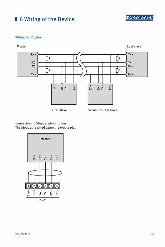
6 Wiring of the Device
Rev. 08/2018 35
Wiring Full Duplex Master Last slave
First slave Second-to-last slave
Connection to Stepper Motor Driver The Modbus is wired using the 6-pole plug.

36 Rev. 08/2018
7.1 Manual and Automatic Operation Adjusting the opening of the throttle or the openings for the gas supply in the gas mixer can be carried out via the stepper motor driver in two operating modes:
– Manual operation
– Automatic operation
Manual and automatic operation can be switched via the Manual/Auto switch or via the MICT. In this case, the MICT overwrites the switch position on the device. You can block the switch-over feature of the Manual/Auto switch based on particular setting in the MICT. If the status LEDs Manual or Auto are lighted up, this indicates the operation mode the stepper motor driver is currently in.
Manual Operation In manual operation, the external input signals of the master control are ignored. You can use the two buttons Open and Close to modify the position of the throttle and the openings of the gas supply for the gas mixer. The stepper motor driver must also be in manual operation for configuration via the MICT and for transferring settings to the device.
Risk of destruction!
In manual operation, the signals of the master control are not analyzed. If you make any adjustments in the manual mode with the gas engine running, make sure that these settings do not endanger the correct operation of the gas engine.
Automatic Operation In automatic operation, the stepper motor driver evaluates the external input signals of the control unit connected. The buttons Open and Close are deactivated. The device cannot be configured via the MICT. In automatic operation, the MICT can only be used to display the data and to create log files.
7.2 Reference Run After the device is switched on or was reset, the VariStep3 stepper motor driver initiates a reference run. This means that the stepper motor determines its current position. In automatic mode, the stepper motor subsequently approaches the position defined by the master control. In manual mode the device connected initially remains in the following position:
– Gas mixer remains in the open position.
– Throttles remain in the closed position.
During reference run, the Offline output is low impedance and the corresponding LED lights up. The signals of the inputs are not analyzed. A reference run can also be triggered via the MICT.
7 Functions

7 Functions
Rev. 08/2018 37
7.3 Open/Closed Positions The Open and the Close position are specified as follows:
– Open: The throttle or the openings for gas supply of the gas mixer are fully opened (100 % open).
– Closed: The throttle or the openings for gas supply of the gas mixer are fully closed (0 % open).
When one of the two positions is reached, the respective binary output Open or Close is switched and the corresponding LED lights up. The connected devices cannot be moved beyond these two positions and all corresponding signals are limited.
7.4 Configurable Opening Angles (Position 1 and 2) The MICT can be used to configure two opening angles, and these openings can be controlled directly via binary inputs (Pos. 1, Pos. 2). If the signals Pos. 1 and Pos. 2 are simultaneously present, position 1 will be approached. When the stepper motor reaches one of the two positions, the respective binary output (Pos. 1, Pos. 2) is switched and the corresponding LED lights up. In this way, you can define the opening angles for certain operating states such as starting or purging the gas engine.
You can configure positions 1 and 2 with the MICT. For further information, refer to the section Positions – Values on page 59.
7.5 Change of Opening Angles via Binary and Analog Inputs In automatic mode the opening angle can be controlled directly via the following inputs.
– Binary inputs Dir and Steps
– Analog voltage input 0-10 V
– Analog current input 0-20 mA
– Field buses CAN and Modbus
Depending on which master control you are using, you can select the required input using the MICT. If one of both end positions (open or closed) has been reached, the signals are limited at the inputs in the corresponding direction.
You can configure the inputs with the MICT. Refer to the section Inputs/Outputs – Control Setup on page 56.

7 Functions
38 Rev. 08/2018
7.6 Analysis of Positions via Analog Outputs or Field Bus The current position of the throttle or the openings of the gas supply for the gas mixer can be sent to the master control via an analog voltage output or an analog current output or a field bus. Using the MICT, it is possible to configure which of the two analog outputs is to be used and which voltage or current value corresponds to the open or close position. The current or voltage applied on the output is then set accordingly proportional to the current opening of the fuel ring.
You can configure the outputs with the MICT. Refer to the section Inputs/Outputs – Control Setup on page 56.
7.7 Access Control You can protect the VariStep3 stepper motor driver against unauthorized access by establishing the access control in the MICT. The access control has four operating levels, three of which can be secured with different PINs. As a default setting, the access control is not activated. If the access control for the stepper motor driver is activated, it is independent from the access levels that control authorizations within the MICT.
Access control
A user is logged in to the Advanced Service access level on the MICT. He changes a configuration and would like to download the change to the stepper motor driver. Although he has the full authorization set in the MICT, he is prompted to log in with the PIN for the Level 3 (Master). This ensures that it is not possible for any user with an MICT and the generally valid password to change the configuration of your stepper motor driver.

7 Functions
Rev. 08/2018 39
Various functions are at your disposal on the four operating levels. The figure below illustrates this:
The following functions are available on the different levels:
– Level 0 (Read Only) Enables read-only access for all users.
– Level 1 (Operator) At this level the user can make position changes (closed and open position, position 1 and position 2, and make manual changes to the opening). Beyond that, he can change the operation mode and can confirm errors.
– Level 2 (Service) The service personnel can also initiate a reference run and reset the counter in the runtime data for the maximum number of step losses that occurred.
– Level 3 (Master) At this level, the master can also reset all PINs and enable or disable the access control. Moreover, only the master is authorized to download a changed configuration to the stepper motor driver.
For information on the access levels in the MICT, refer to the section Access Levels in the MICT on page 41.

40 Rev. 08/2018
MICT is an abbreviation for MOTORTECH Integrated Configuration Tool. You configure your VariStep3 stepper motor driver via the MICT and can adjust it to the master control and the device connected (gas mixer or throttle).
If you are using a different version of the MICT than shown in the following sections, the scope of functions may differ.
8.1 MICT System Requirements For the installation of the MICT, the following minimum requirements must be fulfilled:
– x86-compatible PC, at least performance class Intel Pentium 4 with 2 GHz
– 128 MB free RAM
– 250 MB free disk space
– USB interface 1.1 or higher
– Display with a resolution of at least 1440 x 900 pixels (WXGA+)
– Microsoft® Windows 7, Windows 10
8.2 MICT Installation The software for the installation of the MICT is on the data storage device (USB flash dive or CD-ROM) enclosed with the VariStep3 stepper motor driver.
To install the MICT, proceed as follows:
1. Start the installation:
– Via the menu: Start the file Start.exe on the storage device. Start the installation routine of the MICT via Software -> Install MICT.
– Directly from the storage device: Start the installation routine of the MICT directly. It is on the storage device in the subdirectory Installation and for example named as follows: MICT-2.0.0-setup.exe.
2. Run the installation. Follow the instructions of the installation routine. Note that the license agreement terms must be accepted before using the MICT.
3. Install the USB driver via the menu as well or directly from the storage device.
– Via the menu: Software -> USB Drivers -> Install USB Drivers
– Directly from the storage device: Start the exe file in subdirectory Drivers(e.g. CDM21226_Setup.exe).
▸ You have installed the MICT and can now connect your computer to the stepper motor driver via the USB interface.
8 Settings via the MICT
8 Settings via the MICT
Rev. 08/2018 41
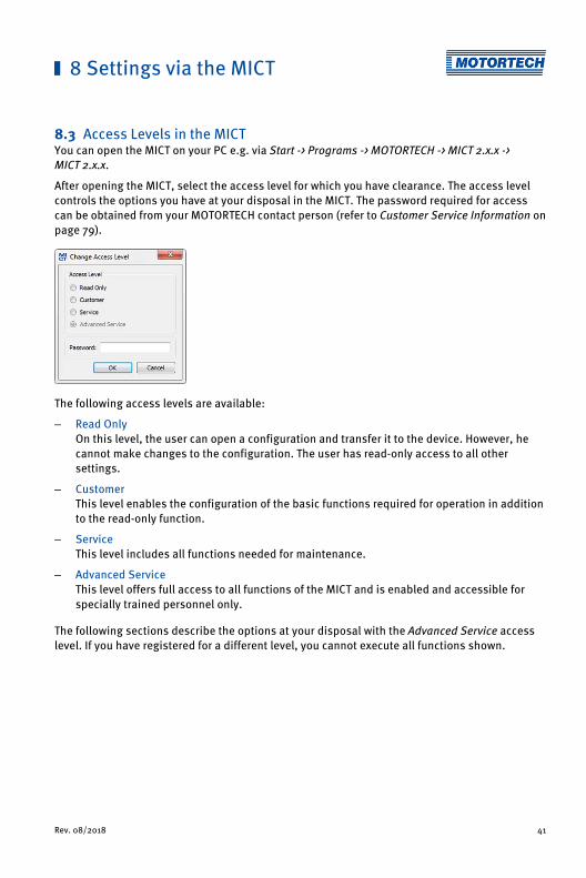
8.3 Access Levels in the MICT You can open the MICT on your PC e.g. via Start -> Programs -> MOTORTECH -> MICT 2.x.x -> MICT 2.x.x.
After opening the MICT, select the access level for which you have clearance. The access level controls the options you have at your disposal in the MICT. The password required for access can be obtained from your MOTORTECH contact person (refer to Customer Service Information on page 79).
The following access levels are available:
– Read Only On this level, the user can open a configuration and transfer it to the device. However, he cannot make changes to the configuration. The user has read-only access to all other settings.
– Customer This level enables the configuration of the basic functions required for operation in addition to the read-only function.
– Service This level includes all functions needed for maintenance.
– Advanced Service This level offers full access to all functions of the MICT and is enabled and accessible for specially trained personnel only.
The following sections describe the options at your disposal with the Advanced Service access level. If you have registered for a different level, you cannot execute all functions shown.

8 Settings via the MICT
42 Rev. 08/2018
8.4 Configuration Pages (Overview) The configuration pages are divided into the following sections:
Item no. Area
Menu bar
Toolbar
Navigation bar
Configuration section
Status bar
The functions in the menu, navigation bar, and the toolbar as well as the configuration section will be described in the following.
The status bar provides you with the following information (from left to right):
– Status display Indicates whether a connection is established with the device:
– Green display: connection established

8 Settings via the MICT
Rev. 08/2018 43
– Red display: the connection was interrupted and is being restored
– Gray display: the connection is not established and is not being restored
– Indication of the interface being used for the connection to the device
– Indication of the device ID
– Indication of the access level of the user in the MICT
– Indication of the operating level for the VariStep3 if access control has been activated and the user has logged on with a PIN.
– Indication of the MICT program version
8.5 Menu Bar and Toolbar The following functions are available to you via the symbols on the toolbar and the entries in the menu bar:
Symbol Menu Function
File -> New Creates a new configuration.
File -> Open Opens an existing configuration.
File -> Save / File -> Save As
Saves the current configuration.
File -> Recent Documents The last five configuration files used are offered for selection.
File -> Close Closes the current configuration.
File -> Open trace Opens a runtime data record (trace file). Refer to the section Runtime Data on page 63.
File -> Open pickup trace Opens a saved recording of pickup signals (putrace file), for example from a MOTORTECH ignition controller. Pickup signals cannot be recorded by the VariStep3.
File -> Change Access Level
Changes the access level for accessing the configuration data and functions.
File -> Print Prints the current configuration.

8 Settings via the MICT
44 Rev. 08/2018
Symbol Menu Function
File -> Print To PDF File Prints the configuration to a PDF file.
File -> Print Preview Opens a print preview of the configuration.
File -> Quit Exits the MICT.
Device -> Connect Connects to the device.
Device -> Disconnect Cuts the connection to the device.
Device -> Download to device
Downloads configuration data from the PC to the device. This function can only be executed in manual mode.
Device-> Upload from device
Uploads configuration data from the device to the PC.
Device -> Runtime data Opens the window Runtime Data. Refer to the section Runtime Data on page 63.
Device -> Log Opens the window Log (Advanced Service only). Refer to the section Log on page 71.
Device -> Select Mode Opens the window Select operation mode in which you can select the operation mode. The following modes are possible: Manual operation mode, Automatic operation mode or Switch controls operation mode.
Device -> Manual Adjustment
Opens a window in which you can manually adjust the opening angle.
Device -> Open Position Completely opens the throttle or the gas supply for the gas mixer in manual mode.
Device -> Close Position Completely closes the throttle or the gas supply for the gas mixer in manual mode.
Device -> Position 1 In manual mode, drives to the position 1 defined in the configuration by a percentage.
Device -> Position 2 In manual operation, drives to the position 2 defined in the configuration by a percentage.

8 Settings via the MICT
Rev. 08/2018 45
Symbol Menu Function
Device -> Reference Run Initiates a reference run in manual mode (Service and Advanced Service only).
Device -> Temperature Extremes
Opens a window in which the maximum and minimum temperature are displayed. These values are measured throughout the operating time on the board of the stepper motor driver.
Device -> Error Acknowledge
All operating errors are acknowledged.
Device -> Trigger Error The process carried out by the stepper motor driver (e.g. a reference run), is canceled and the stepper motor driver switches into error mode.
Device -> Access Control The setup for the access control to the device is described in a separate section. Please read the section Access Control of the Stepper Motor Driver on page 47.
Settings -> Language Opens the window Select Language in which you can change the interface language of the MICT.
Settings -> Online update settings
Opens the window Online Update Settings. Refer to the section Online Update Settings on page 46.
Settings-> Database settings
Opens a dialogue window in various databases can be assigned as source for the MICT.
Settings -> Temperature scale
Opens the window Select Temperature Scale, in which you can change the unit for the temperatures shown in the MICT.
Settings -> Display by cylinders
This function is available for certain MOTORTECH ignition controllers and has no effect in conjunction with the VariStep3.
Document Has no function with the VariStep3.
Tools -> Coils Opens a database with information on MOTORTECH ignition coils.
Help -> Help Opens the online help function.
Help -> About MICT Opens detailed information on the MICT.

8 Settings via the MICT
46 Rev. 08/2018
8.6 Online Update Settings The MICT uses data from various databases for the configuration. Such data can be updated with automatic online updates. The settings for the update can be entered with the following entry in the menu bar:
Settings -> Online update settings
You have the following options:
– Enable automatic database updates Using the check box, you can enable and disable automatic online updates. As the default setting, the online update is activated and is executed daily (if an internet connection is established) at first start-up of the MICT.
– Use a proxy to access the web Use the checkbox to activate settings for internet access via a proxy server, which you can then set up by entering http-Proxy and Port.
– Show Log With this button, you can open a window in which the online updates performed are logged.
– Update Now With this button, you manually start an online update.
Online update
After the online update, the updated data will only be used if these have been downloaded onto the device. However, this requires the relevant authorization.
Whenever the configuration is uploaded from the device, the version of the configuration saved in the device will be compared with the version in the database. If the two versions are not the same, a window with additional instructions will open up.

8 Settings via the MICT
Rev. 08/2018 47
8.7 Access Control of the Stepper Motor Driver If the access control to the stepper motor driver is activated, access to the following areas is possible with a PIN only:
– Troubleshooting
– Position changes (open, closed, position 1 and 2, manual adjustment, reference run)
– Configuration (transfer of a configuration to the stepper motor driver)
The access control regulates the accesses to the stepper motor driver via the MICT. For explanations concerning access control of the stepper motor driver and the delimitation of the access levels in the MICT, refer to section Access Control on page 38.
The access control functions can be accessed in the menu bar via:
Device -> Access Control
8.7.1 Enable/Disable Access Control
Enable/Disable access control
As a default setting, the access control is not activated, and all PINs are set to 0000. Once the access control has been activated, and the PINs were changed, these PINs will continue to be used. To activate the access control again, you will need the PIN for level 3 (Master). It is therefore recommended to reset all PINs before disabling.
If that was not done, or a system must be unlocked for another reason, a request key can be issued in the MICT. Refer to the section Reset all PINs on page 48.
To enable or disable the access control, proceed as follows:
1. Open the input dialog via Device -> Access Control -> Enable or Disable access control.
2. Enter the PIN for the level Master (Level 3).
3. Confirm the input with OK.
8.7.2 Login/Logout If the access control is activated, you are prompted to log in if you want to execute functions that are allocated to a specific operating level. In addition, you can log in specifically to an operating level via the menu bar.
To log into a specific operating level, proceed as follows:
1. Open the input dialog via Device-> Access Control -> Login.
2. First select the level you wish to log on to.

8 Settings via the MICT
48 Rev. 08/2018
3. Enter the PIN for the desired level.
4. Confirm the input with OK.
▸ You are now logged into the corresponding level and can execute all functions that are allocated to this operating level without having to log in again.
After completing the log-in, you can log out again as follows:
Device -> Access Control -> Logout
8.7.3 Changing the PIN To change the PIN for a specific operating level, proceed as follows:
1. Open the input dialog via Device -> Access Control -> Change PIN.
2. First select the level for which you wish to change the PIN.
3. Enter the current PIN for the desired level.
4. Enter the new PIN in the two subsequent fields.
5. Confirm the input with OK.
▸ The PIN for this operating level has now been changed.
8.7.4 Reset all PINs To reset all PINs, proceed as follows:
1. Open the input dialog via Device -> Access Control -> Reset all PINs.
2. If you are not yet logged into the Master (level 3) level, you will be prompted to log in with the relevant PIN.
3. Confirm the input with OK.
4. To reset all PINs, you will be prompted again to enter the PIN for the level Master (Level 3).
5. Confirm the input with OK.
▸ All PINs are now reset to the value 0000.
To reset all PINs, you need the PIN for the level Master (level 3). To be able to unlock a system in case of emergency that was locked in this way, you have the following option:
1. In the menu bar, select the entry Device -> Access Control -> Get reset all PINs request key to open a window with the same name.
2. Send the request key with the serial number to your service contact person at MOTORTECH (refer to Customer Service Information on page 79). This key is valid only for the respective controller and only for a certain amount of time.
▸ Your information will be verified, and you will receive an authorization key from your contact person.
8 Settings via the MICT
Rev. 08/2018 49
3. From the menu bar, select the entry Device -> Access Control -> Set reset all PINs authorization key to open a window with this name.
4. Enter the authorization key received in the input field.
5. Confirm the input with OK.
▸ If the input was correct, all PINs are reset to the default value 0000.
8.8 Working with Configurations To ensure that the VariStep3 stepper motor driver interprets incoming data correctly and converts them to the desired control signals, it requires information on the device connected and the master control connected. This information is stored in a configuration file on the stepper motor driver.
You need the MICT for the following tasks:
– Creating configuration files
– Opening configuration files from a storage device
– Processing configuration files
– Saving configuration files on a storage device
– Downloading configuration files to a VariStep3 stepper motor driver
– Uploading configuration files from a stepper motor driver
– Displaying current and saved runtime data

8 Settings via the MICT
50 Rev. 08/2018
8.8.1 Create, Open, Save
Click on the symbol to create a new configuration and select the entry Stepper Motor Cards -> VariStep3.
Click on the symbol to open a saved configuration.
Click on the symbol to save the configuration currently displayed in the MICT to a storage device.

8 Settings via the MICT
Rev. 08/2018 51
8.8.2 Upload, Download
Click the symbol to upload the current configuration from the VariStep3 stepper motor driver to the MICT. If applicable, the MICT first establishes a connection to the stepper motor driver connected.
Click the symbol to download the configuration set in the MICT to the VariStep3 stepper motor driver. This function can only be executed when the stepper motor driver is in manual mode. This action overwrites the existing configuration on the device. If applicable, the MICT first establishes a connection to the stepper motor driver connected.
Existing configuration is cleared!
If you download a configuration to a VariStep3 stepper motor driver, the previously used configuration is deleted and the new settings are immediately implemented.
8.8.3 Compatibility Information
If you upload a configuration from the VariStep3 stepper motor driver to the MICT that does not correspond to the status of your MICT, or if you open this type of configuration in the MICT, the following situations may occur:
– No values are present in the configuration for certain MICT functions. The MICT assumes the standard values for these functions.
– The configuration contains function values that are not support by the MICT.
The following situations can occur if you download a configuration from the MICT to a VariStep3 stepper motor driver whose firmware does not correspond to the status of your MICT:
– No values are present in the configuration for certain firmware functions. The firmware continues to use the preset values for these functions.
– The configuration contains function values that are not support by the firmware.
If you download a configuration to the stepper motor driver and are notified of functions that are not supported by the MICT, you should check the stepper motor driver settings. Re-upload the configuration from the stepper motor driver to the MICT. You can then see which settings are not transmitted to the MICT.
8 Settings via the MICT
52 Rev. 08/2018
Perform a firmware update, if necessary and/or update your MICT so that you can use all the functions of the VariStep3 stepper motor driver without restriction.
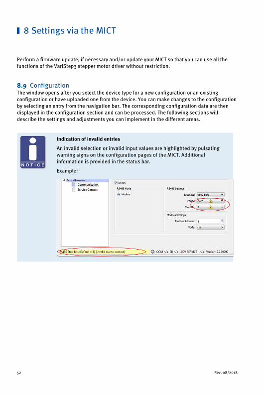
8.9 Configuration The window opens after you select the device type for a new configuration or an existing configuration or have uploaded one from the device. You can make changes to the configuration by selecting an entry from the navigation bar. The corresponding configuration data are then displayed in the configuration section and can be processed. The following sections will describe the settings and adjustments you can implement in the different areas.
Indication of invalid entries
An invalid selection or invalid input values are highlighted by pulsating warning signs on the configuration pages of the MICT. Additional information is provided in the status bar.
Example:

8 Settings via the MICT
Rev. 08/2018 53
8.9.1 External Device
To change the device type, approval for the access level Advanced Service is required.
Device type Select the device type you wish to configure and control with the VariStep3 stepper motor driver from the drop-down list.
When the device type has been changed and the modified device configuration has been downloaded to the device, the Status LED flashes orange. This indicates that a reference run in required.
– Gas Mixer Select this option in order to select from the following drop-down list the type of gas mixer that corresponds to the device that you want to configure (e.g. VF2 200-120 Rev. B for a VariFuel2 type 200-120 with a revision B stepper motor). Note the stepper motor revision when making your selection. Type RK1 corresponds to the stepper motor conversion kit for gas mixers (MWM TBG620 series).
– Throttle Select this option to select the throttle from the following drop-down list with integrated stepper motor (ITB) or the throttle gear (TG) that corresponds to your application.

8 Settings via the MICT
54 Rev. 08/2018
– Unknown This option corresponds to the factory setting and cannot be reassigned once the device has been changed.
– None Select this option if you want to shut down or store your VariStep3 stepper motor driver temporarily. In addition, this option can be selected if the VariStep3 stepper motor driver was configured for one device type and is then to be used for another device type. For this, also read the information box Changing the device type. If the device type has been changed to None and the modified configuration has been downloaded to the device, the Status and Manual/Auto LEDs are flashing orange.
Note the stepper motor revision
The revision of the stepper motor can be identified from the nameplate on the stepper motor of your VariFuel2.
VariFuel2 stepper motors whose revisions are not stated on the nameplate or which are supplied without a nameplate are revision A stepper motors. For revision A, select the entry for your VariFuel2 type without a revision specification under External Device (e.g. VF2 200-120 for a VariFuel2 type 200-120 with revision A stepper motor).
If no VariFuel2 types with matching stepper motor revision are displayed under External device, the VariFuel database of your MICT is not up-to-date. In this case, perform an online update. For further information, refer to the section Online Update Settings on page 46.

8 Settings via the MICT
Rev. 08/2018 55
Changing the device type
The process how to exchange one VariFuel2 type for another is described below. However, the process can also be carried out correspondingly if you change the device type. For example, you want to use the VariStep3 which you used for a VariFuel2 gas mixer for a throttle.
Scenario: You have replaced one VariFuel2 gas mixer with another VariFuel2 type.
Problem: After connecting the new VariFuel2 gas mixer, the stepper motor driver performs a reference run. However, since this configuration still contains data from the first gas mixer, it is possible that the VariFuel2 may leave the traversing range and be mechanically damaged as a result, or there is a risk that the VariFuel2 has to be readjusted.
Solution: The following procedure will help to solve the problem:
1. Separate the first VariFuel2 from the stepper motor driver.
2. Connect the MICT to the stepper motor driver.
▸ The defective connection with the stepper motor causes an operating error.
3. Switch to manual mode.
4. Acknowledge the error via the MICT (Device -> Error Acknowledge).
5. Change the configuration to the new VariFuel2 type.
6. Download the altered configuration to the device.
7. Separate the stepper motor driver from the supply voltage.
8. Connect the new VariFuel2 with the stepper motor driver.
9. Reconnect the stepper motor driver to the supply voltage.
▸ A reference run will be performed. The new VariFuel2 is then ready for operation.
Tip: When you first configure the VariStep3 stepper motor driver with the option None in the drop-down list Device Type no operating error is triggered after the device has been separated from the stepper motor driver. You can now reconfigure the stepper motor driver directly.

8 Settings via the MICT
56 Rev. 08/2018
8.9.2 Inputs/Outputs – Control Setup
The settings on the configuration page depend on the inputs and outputs used by your master control. In this case, refer to all information given in the relevant documentations of the control units. To make changes, approval for the access level Advanced Service is required.
Selection – Input
Select the input that is to be used for position setting by the master control connected. The following options are possible:
– Analog voltage Position setting is achieved via the analog voltage signal.
– Analog Current Position setting is achieved via the analog current signal.
– Digital Steps/Dir Position setting is achieved via binary signals (Steps, Dir).
– Field bus Position setting is achieved via a field bus. This requires corresponding configuration of the communication with the desired field bus (see Miscellaneous – Communication on page 60).

8 Settings via the MICT
Rev. 08/2018 57
– Output Select the analog output that is to be used by the master control connected.
– External manual/automatic selection enabled Disable the check box to deactivate the Manual/Auto switch on the stepper motor driver. The stepper motor driver may then only be put in manual mode via the MICT with the corresponding authorization.
Input Voltage/Input Current Depending on which input is selected, you have different adjustment options available. For the analog inputs, enter the values for the open and closed position of the fuel ring. Here, please adhere to the following values:
– Input voltage: 0 V to 10 V
– Input current: 0 mA to 20 mA
Click this button to apply the settings of the analog input (current or voltage) to the output selected. If you have selected another input as output (e. g. input: current; output: voltage), the adjusted values are converted in accordance with the output's value range.
Input Step Count/Step Count Configuration Define both the Direction and the Init Position of the steps of the binary inputs. The initial position (=Init Position) will be approached after the reference run of the stepper motor.
To make these settings, refer to all additional information as provided in the following note.
Output Voltage/Output Current Depending on the selection, enter the relevant current or voltage values, which are to correspond to the open and closed position. Here, the same value ranges are applicable as with the analog inputs.

8 Settings via the MICT
58 Rev. 08/2018
Settings of the input selected
Analog Inputs (Current or Voltage) Based on the values used by your master control, you can define the values of the Open and the Close position for the analog inputs in the MICT. The value applied to the input is then converted proportionally to the values entered in a corresponding opening angle of the throttle or the fuel ring of the VariFuel2.
Example:
Your master control works with a current input of 4 mA to 20 mA. In the MICT, you configure 4 mA to refer to the closed position and 20 mA to the open position. If the current on the input is now 16 mA, the opening is 75 %.
Binary inputs In the MICT, enter the settings for the binary inputs Dir and Steps. The level on the Dir determines the direction in which the fuel ring of the VariFuel2 or the throttle will move if there are pulses on the Steps.
Example:
You have selected the option High -> Open in the MICT under Direction. If a high level is applied on the Dir, with each pulse on the Steps one step is added to the current position. The fuel ring or throttle will then move gradually from the Closed to the Open direction.
Unused inputs and outputs
Please note that the terminals for the analog inputs and outputs not selected in the MICT must remain unoccupied.

8 Settings via the MICT
Rev. 08/2018 59
8.9.3 Positions – Values
Position 1/Position 2 You can define two configurable positions using these two input fields. This requires approval for the access level Service or Advanced Service. Enter the desired opening angle of the gas supply for the gas mixer or throttle as a percentage value (100 % corresponds to open, 0 % corresponds to closed). The openings specified here can be set in manual mode via the MICT and in automatic mode via fieldbus or via the binary inputs of the stepper motor driver.
For further information, refer to the section Configurable Opening Angles (Position 1 and 2) on page 37.

8 Settings via the MICT
60 Rev. 08/2018
8.9.4 Miscellaneous – Communication
CAN Via the field CAN, deactivate or activate the CAN interface of the device.
– ALL-IN-ONE (J1939)/CANopen Select the desired protocol, depending on whether you want to set the communication for the ALL-IN-ONE or for another master control.
– Source Address/CANopen Node ID In the protocol ALL-IN-ONE (J1939) the source address can be assigned between 0 and 253. In the CANopen protocol, a CANopen node ID from 1 to 127 can be assigned. Note that IDs cannot be assigned more than once.
– Baudrate Select the desired data transfer rate from the list. In the protocol ALL-IN-ONE (J1939), 250 kbit/s and 500 kbit/s are available for selection. In the CANopen protocol, a baud rate from 50 kbit/s to 1 Mbit/s can be set. For both protocols, we suggest the use of a baud rate of 250 kbit/s.

8 Settings via the MICT
Rev. 08/2018 61
RS485
Via the field RS485, deactivate or activate the RS485 interface of the device.
– RS485 Settings
– Baudrate Select the desired data transfer rate from the list. The Modbus baud rate can be defined between 9600 bit/s and 115200 bit/s, the recommended value being 19200 bit/s.
– Parity Define if a parity bit is used and if the parity is to be even or odd.
– Stopbits Determine if one or two stop bits are to be sent. Two stop bits can only be sent if no parity has been selected.
– Modbus Settings
– Modbus Address The Modbus address can be assigned between 1 and 247. Note that IDs cannot be assigned more than once.
– Mode Define if the data are transferred in the ASCII or RTU mode.
Setting the transfer rate
Please note that all devices connected with a bus must be set to the same transfer rate.

8 Settings via the MICT
62 Rev. 08/2018
8.9.5 Miscellaneous – Service Contact This configuration page can be viewed by all users, but changes can only be made with authorization for the Advanced Service access level.
Service Contact In this area, you can store individual contact data.

8 Settings via the MICT
Rev. 08/2018 63
8.10 Runtime Data
Click on the symbol to open the window Runtime Data. The following sections will give you an overview of the data you can view on the individual tabs.
You can print and record the runtime data. For this purpose, the following functions are at your disposal in the toolbar in the window:
Symbol Function
Prints the runtime data.
Prints the runtime data to a PDF file.
Opens the print preview.
Starts the runtime data trace.
Stops the runtime data trace.
Save runtime data locally
You should always save runtime data on the local computer and not on a network drive or external storage device. Trace files can only be moved freely once the recording is stopped.

8 Settings via the MICT
64 Rev. 08/2018
8.10.1 Runtime Data – Overview
In this screen, you can find the following information:
Configured The status display indicates if the stepper motor driver has a valid configuration:
– green: The stepper motor driver has a valid configuration.
– red: The stepper motor driver has no or an invalid configuration. An existing configuration can for example become invalid during a firmware update. A valid configuration must be downloaded to the stepper motor driver in order to make the device operational.
Reference Run The status display provides information on the reference run:
– green: The reference run was completed successfully.
– yellow: The reference run is being carried out.
– red: Errors occurred during the reference run. The reference point was not found.
8 Settings via the MICT
Rev. 08/2018 65
Manual/Auto The status display indicates the operation mode selected:
– green: The operation mode is set.
– yellow: A command is carried out in the operation mode selected. In automatic operation mode, the status display will only turn yellow if position 1 or 2 is approached.
– red: An error occurred in the operation mode selected.
Stepper Motor The status display indicates the condition of the stepper motor:
– green: The stepper motor is ready.
– yellow: The stepper motor is active.
– red: An error occurred.
Warning/Error A red status display indicates that an error or a warning message occurred. The display will go out if the error or warning is acknowledged via the MICT (Device -> Error Acknowledge). Refer to the section Runtime Data – Message Log on page 66.
Opening – Target
The value is assigned to the stepper motor driver in automatic mode by the master control or, in manual mode, by the MICT or the Open/Close buttons on the device.
– Actual The displayed value corresponds to the opening percentage of the throttle or the gas supply of the gas mixer.

8 Settings via the MICT
66 Rev. 08/2018
8.10.2 Runtime Data – Message Log
In the view Message Log, information, warnings and errors are listed.
The following information is provided:
– Operating Hours Operating hours counter reading at the time of message
– Time Time and date cannot be shown for VariStep3 stepper motor drivers.
– Category Message type (information, warning, error)
– Message Message text; you can find more information on the message text in the following sections.

8 Settings via the MICT
Rev. 08/2018 67
You have the following options:
– Automatic scrolling If this box is checked, the system automatically displays the last list entry until a new event occurs.
8.10.2.1 Information Information
Configuration changed.
Device (firmware version) started at a supply voltage of value.
Device switched off.
Message log cleared.
NVRAM formatted.
One or more messages are lost due to exhausted memory pool or message queue overrun.
Shutdown timestamps cleared.
Step control heavy load.
Step loss error self acknowledged.
For each information, the status of the stepper motor driver at the time the information occurred is provided. Additional parameters are provided if necessary.
8.10.2.2 Warnings Warning
Cpu usage.
General warning.
Reset life time.
Step control overload.
Use backup life time.
For each warning, the status of the stepper motor driver at the time the warning occurred is provided. Additional parameters are provided if necessary.

8 Settings via the MICT
68 Rev. 08/2018
8.10.2.3 Errors Errors
CAN handler message queue full.
Error triggered by command.
Coprocessor handler message queue full.
General error.
Input handler message queue full.
Interframe step loss.
Low Power
Output handler message queue full.
Over current.
Over temperature.
Stop step loss.
Timeout.
For each error message, the status of the stepper motor driver at the time the error occurred is provided. Additional parameters are provided if necessary.

8 Settings via the MICT
Rev. 08/2018 69
8.10.3 Runtime Data – Diagnostics
In this screen, you can find the following information:
Operation mode The operation mode section shows which operation mode (Manual or Automatic) is currently active and how the operation mode was adjusted. Here, there are the following two options:
– Ctrl Displays whether the operation mode was adjusted using the MICT or the switch Manual/Auto on the device (Hardware).
– Mode The set operating mode is displayed.
States This area shows the current conditions of the stepper motor driver, the stepper motor and all individual phases of the reference run.

8 Settings via the MICT
70 Rev. 08/2018
CPU Load Current capacity utilization of the processor.
Supply voltage Current supply voltage of stepper motor driver.
Current Temp. Current temperature of board.
Max Temp Maximum reached temperature of the board since the stepper motor driver was switched on the last time.
Min Temp Minimum reached temperature of the board since the stepper motor driver was switched on the last time.
Max. Step Loss Internal diagnosis parameters associated with the control of the stepper motor. The maximum step losses that have occurred since the last switch-on are displayed. If the step losses are too high, this will cause an error message.

8 Settings via the MICT
Rev. 08/2018 71
8.10.4 Runtime Data – Information
In this view, you can find an overview of the device and version data. You can also print the current runtime data or, in case of problems, send them to the MOTORTECH Service Department via fax or as a PDF file via e-mail. For fast support, we will then immediately have all required information.
8.11 Log
Click on the symbol to open the window Log. This window is only available to users with authorizations starting at the access level Advanced Service.

8 Settings via the MICT
72 Rev. 08/2018
The window Log serves to support error diagnostics by MOTORTECH.
– Automatic scrolling If the function is active, the view panel focuses on the latest message.
– Log level The selection of the log level is specified by MOTORTECH if needed.
– Write log to file This checkbox activates or deactivates, respectively, the saving of the logged data in a selected file. If the function is disabled, the logged data are merely shown on the display.
– Select file With this button, you can select a file to which you want to save the logged data.
If you are prompted to create a log file in the case of a service request, proceed as follows:
1. Open the window Log via the toolbar or the menu bar.
2. Select a path with the Select file button and enter the file name for the log file.
▸ If the file does not yet exist, it is automatically created with the extension .log.
3. Activate the checkbox Write log to file.
4. Select the level specified by MOTORTECH from the list Log level.
5. Leave the window open.
▸ The log messages are logged both in the window and in the selected file.

Rev. 08/2018 73
9.1 Firmware Update Using the MOTORTECH Flash Tool, you can perform a firmware update for the stepper motor driver. The program is provided on the storage device (USB flash drive or CD-ROM supplied).
Install MOTORTECH Flash Tool Install the MOTORTECH Flash Tool as follows:
1. Start the installation:
– Via the menu: Start the file Start.exe on the storage device. Start the installation routine for the MOTORTECH Flash Tool via Software -> MOTORTECH Flash Tool -> Install MOTORTECH Flash Tool.
– Directly from the storage device: Start the installation routine of the MOTORTECH Flash Tool directly. It is on the storage device in the subdirectory Installation and for example named as follows: MOTORTECH-Flash-Tool-0.9.00003-setup.exe.
2. Install the program. Follow the instructions of the installation routine. Note that the license agreement terms must be accepted before using the MOTORTECH Flash Tool.
3. If the USB driver is not yet installed, also install it via the menu or directly from the storage device.
– Via the menu: Software -> USB Drivers -> Install USB Drivers
– Directly from the storage device: Start the exe file in subdirectory Drivers (e.g. CDM v2.10.00 WHQL Certified.exe).
▸ The MOTORTECH Flash Tool is set up. You can now connect your PC to the stepper motor driver via the USB interface.
9 Operation

9 Operation
74 Rev. 08/2018
Menu Bar and Toolbar After launching the MOTORTECH Flash Tool, the following functions are available to you via the icons on the toolbar and the entries in the menu bar:
Symbol Menu Function
File -> Open Opens a firmware file.
File -> Quit Exits the program.
View -> Extended file information view
Fades in / out additional information of the firmware file.
View -> Extended connection settings
Fades in / out additional information and settings of the connection to the device.
View -> Reload file Reloads the file information of the selected firmware file.
Device -> Search devices Restarts the search for connected devices.
Device -> Flash device Starts the update process or downgrade process.
Settings -> Language Opens the window Select Language in which you can change the interface language of the program.
Help -> Help Opens the online help function.
Help -> About MOTORTECH Flash Tool
Opens detailed information on the program.
Start Firmware Update
Access control for firmware update
If you have activated the access control for the device, you need the PIN for the level Master for the firmware update. For more information read the section Access Control of the Stepper Motor Driver on page 47.

9 Operation
Rev. 08/2018 75
Backup the existing configuration
Your device's configuration may be lost if the firmware update is not performed properly. Always backup the existing configuration via the MICT prior to performing an update. For more information read the section Working with Configurations on page 49.
To start a firmware update, proceed as follows:
1. If an MICT is connected with the stepper motor driver, disconnect this connection.
2. Start the MOTORTECH Flash Tool via Start -> Programs -> MOTORTECH -> MOTORTECH Flash Tool -> x.x.x (e.g. 0.9.00003) -> MOTORTECH Flash Tool.
▸ The MOTORTECH Flash Tool will now start.
▸ The software automatically checks all ports for connected devices.
3. In the Status section under Device, check if your device has been recognized properly.
▸ If the MOTORTECH Flash Tool does not recognize a device that is connected to your PC via the USB interface, you can usually still carry out a firmware update. To do so, observe the instructions in the information windows of the MOTORTECH Flash Tool for the following steps.
4. Select in area File using the Select button the desired update file.
5. By reading the displayed file information, ensure that the update file is correct for your device.
6. Start the update process using the Flash button or using the menu or toolbar.
▸ The stepper motor driver will be restarted automatically.
▸ Now, a window opens informing you about the firmware version currently used on your stepper motor driver and also about the relevant update version.
7. Confirm with Yes to proceed with the update process.
▸ Now the update will start.
▸ If the firmware update was successful, you will see a relevant message.
▸ Now, the stepper motor driver will initiate a reference run.
8. After a successful firmware update, check all configuration data.
Downgrade process
The process for a downgrade is largely the same as the update process. You will only be informed that a new firmware has been installed on the device.

9 Operation
76 Rev. 08/2018
Help with connection problems
If a correctly connected device is not found during the automatic search, this can, for example, be because too many communication interfaces are assigned and must be checked. In this case, an interface from the drop-down list Port in the area Connection can be selected and thus specified.
If the desired port is not yet displayed in the list or if the problem should continue, an adjustment of the time-outs for the connection helps. The time-out settings are displayed in the main view by the following entry in the menu bar: View -> Extended connection settings
Enter the following settings:
– Update Request Timeout Adjustment range: 1000 ms to 10000 ms, standard value: 3000 ms. An extension of the time-out can be an advantage, especially with connection problems that occur because the computer has many assigned ports.
– Time-out for the Start adjustment range: 1000 ms to 10000 ms, standard value: 3000 ms. A time-out change can be an advantage, especially with connection problems that occur because the communication between the computer and the device has been interrupted.

Rev. 08/2018 77
10.1 Troubleshooting If the stepper motor driver detects any error, the LED status starts blinking in red. You can find details about status signaling in the following information box. In automatic mode, the binary output Error is also activated in the event of a fault and the corresponding LED lights up. Using the MICT you can see the type of error occurred. Refer to the section Runtime Data – Message Log on page 66.
Status signaling
The status of the VariStep3 stepper motor driver is signaled via the LED Status.
– Flashing green: Error-free operation
– Flashing orange: Warning Warnings can be acknowledged by simultaneous pressing of buttons Open and Close (in manual Mode) or by the external reset signal. Warnings can for example be caused by:
– Overload of the device
In addition, the LED flashes orange for the following reasons.
– No device type has been configured (device type: None or Unknown).
– Device connected was changed.
– Overtemperature or over current error confirmed by MICT.
– A reference run is required.
The first two cases make downloading a modified configuration to the device a priority.
– Flashing red: Error Errors can be acknowledged by simultaneous pressing of buttons Open and Close or by the external reset signal. Errors can for example be caused by:
– Step loss
– Overtemperature
– Low voltage
– Over current
– Alternate flashing of red and green: The supply voltage for the device was too low during start up.
10 Errors

10 Errors
78 Rev. 08/2018
10.2 Possible Faults Low Power Supply voltage has dropped below 11 V.
Potential causes:
– The power supply is dimensioned too small.
– The battery is worn out.
– The wiring for the power supply is defective.
– The wiring for the power supply is routed incorrectly.
Step loss The steps predefined by the stepper motor driver have not been carried out by the stepper motor.
Potential causes:
– The belt tension of the VariFuel2 is too high.
– The fuel ring of the VariFuel2 or throttle is stuck (e.g. due to deposits).
– The wiring to the stepper motor is defective or incorrect.
– The stepper motor is defective.
Overtemperature The temperature of the board of the stepper motor driver has been exceeded.
Potential causes:
– The ambient temperature is too high.
– Air circulation around the device is insufficient.
Reference run failed It was not possible to determine the reference point of the stepper motor.
Potential causes:
– The belt tension of the VariFuel2 is too high.
– The fuel ring of the VariFuel2 or throttle is stuck (e.g. due to deposits).
– The wiring to the stepper motor is defective or incorrect.
– The stepper motor is defective.
Overcurrent The current running to the stepper motor is too high.
Potential causes:
– The wiring to the stepper motor is defective or incorrect.
– The stepper motor is defective.
– The stepper motor driver is defective.

10 Errors
Rev. 08/2018 79
Device does not react The throttle connected or gas mixer connected does not react to the signals of the stepper motor driver.
Potential causes:
– The connection between the stepper motor and throttle or gas mixer has been interrupted.
10.3 Acknowledging Faults In manual mode, you have the following options for acknowledging operating errors:
– Via Error confirmation in the MICT
– By pressing the Open and Close button simultaneously
In automatic mode, you have the following options for acknowledging operating errors:
– The master control sends a signal to the binary reset input
– By pressing the Open and Close button simultaneously
– Via Error confirmation in the MICT
Critical errors can only be acknowledged by switching the device off and on.
Error confirmation in automatic operation
If the VariStep3 stepper motor driver is in automatic mode and an error immediately reoccurs after the acknowledgment of this error via the MICT, switch over into the manual mode before re-acknowledging the error again. After you have acknowledged the error, you can correct a defective configuration and transfer it to the device via download.
10.4 Customer Service Information You can reach our customer service during business hours at the following phone and fax number, or by email:
Phone: +49 5141 93 99 0
Fax: +49 5141 93 99 99
Email: [email protected]

10 Errors
80 Rev. 08/2018
10.5 Returning Equipment for Repair/Inspection To return the device for repair and inspection, obtain a return form and return number from MOTORTECH.
Fill out the return form completely. The completely filled out return form guarantees fast, uncomplicated processing of your repair order.
Send the device and the return form to one of the two addresses below or to the nearest MOTORTECH representative:
MOTORTECH GmbH Hogrevestr. 21-23 29223 Celle
Germany
Phone: +49 5141 93 99 0 Fax: +49 5141 93 99 98
www.motortech.de [email protected]
MOTORTECH Americas, LLC 1400 Dealers Avenue, Suite A New Orleans, LA 70123
USA
Phone: +1 504 355 4212 Fax: +1 504 355 4217
www.motortechamericas.com [email protected]
10.6 Instructions for Packaging the Equipment For return shipment, equipment should be packaged as follows:
– Use packaging material that does not damage the equipment surfaces.
– Wrap the equipment with sturdy materials and stabilize it inside the packaging.
– Use sturdy adhesive film to seal the packaging.

Rev. 08/2018 81
11.1 Spare Parts and Accessories For spare parts and accessories, please refer to our current Product Guide, which is available for you to download on the internet at www.motortech.de.
11 Maintenance

82 Rev. 08/2018
12.1 Replacement of the Stepper Motor Driver
12.1.1 VariStep to VariStep3 Stepper Motor Driver
Replacing VariStep and VariStep3
Pin assignment of connectors is identical for the VariStep and VariStep3 stepper motor drivers except for the connector Analog Inputs/Outputs. The identical plugs can simply be plugged from the old device into the new device. This also applies to CAN and Modbus (RS485) interfaces.
The socket for the stepper motor and encoder for the VariStep3 stepper motor driver has 12 poles. However, the 11-pole plug can still be used. It just needs to be plugged in at the far right. Pin 0 of the socket is currently not in use and therefore locked.
When changing the plug for the power supply, be aware that Earth and negative pole (–) must be connected separately on the VariStep3.
Assignment of the wire colors
Take the assignment of the wire colors of the wiring harness from the wiring diagram enclosed with the wiring harness.
12 Annex

12 Annex
Rev. 08/2018 83
VariStep3 Stepper Motor Driver (P/N 31.01.960)
VariStep Stepper Motor Driver (P/N 31.01.955)
Binary inputs
Binary outputs
Analog Inputs/ Outputs
Digital Inputs
Digital Outputs
Analog Inputs/ Outputs
CAN Modbus
(RS485) Stepper Motor + Encoder
Power CAN Modbus (RS485)
Power IN Stepper Motor + Encoder
Connector Digital Inputs -> Connector Binary Inputs
Labeling VariStep Pin Labeling VariStep3
DIRin + 1 Dir +
DIRin - 2 Dir -
STEPSin + 3 Steps +
STEPSin - 4 Steps -
POS1in + 5 Pos. 1 +
POS1in - 6 Pos. 1 -
POS2in + 7 Pos. 2 +
POS2in - 8 Pos. 2 -
RESET + 9 Reset +
RESET - 10 Reset -

12 Annex
84 Rev. 08/2018
Connector Digital Outputs -> Connector Binary Outputs
Labeling VariStep Pin Labeling VariStep3
ERRORout + 11 Error +
ERRORout - 12 Error -
CLOSEout + 13 Close +
CLOSEout - 14 Close -
OPENout + 15 Open +
OPENout - 16 Open -
POS1out + 17 Pos. 1 +
POS1out - 18 Pos. 1 -
POS2out + 19 Pos. 2 +
POS2out - 20 Pos. 2 -
OFFLINEout + 21 Offline +
OFFLINEout - 22 Offline -
Connector Analog Inputs/Outputs
Labeling VariStep Pin VariStep Pin VariStep3 Labeling VariStep3
Uin + 23 23 Position U in +
Uin GND 24 24 Position GND
Iin + 25 25 Position I in +
Iin - 26 26 Position I in -
– – 27 Shield
Uout + 28 29 Position U out +
Uout/Iout GND 29 30 Position GND
Iout + 30 31 Position I out +
Connector Power
Labeling VariStep Pin VariStep Pin VariStep3 Labeling VariStep3
Power IN + 1 1 L +
Power IN - (Earth) 2 2 L -
Power IN - (Earth) 3 3 Earth

12 Annex
Rev. 08/2018 85
Connector Stepper Motor + Encoder
Labeling Pin VariStep/ VariStep3
Encoder GND 1
Encoder 5V/Power 2
Encoder A 3
Encoder B 4
Encoder I 5
Encoder Shield 6
Stepper Motor Phase B2 7
Stepper Motor Phase B1 8
Stepper Motor Shield 9
Stepper Motor Phase A2 10
Stepper Motor Phase A1 11
12.1.2 VariFuel2 to VariStep3 Stepper Motor Driver
Assignment of the wire colors
Take the assignment of the wire colors of the wiring harness from the wiring diagram enclosed with the wiring harness.

12 Annex
86 Rev. 08/2018
VariStep3 Stepper Motor Driver (P/N 31.01.960)
VariFuel2 Stepper Motor Driver (P/N 31.01.951, 31.01.950-X)
Binary inputs
Binary outputs
Analog Inputs/ Outputs Connector 4 Connector 3
CAN Modbus
(RS485) Stepper Motor + Encoder
Power Connector 1 Connector 2 DIL1*
DIL Switch is ON (top position)
Connector Binary Inputs
Pin VariStep3 VariFuel2 stepper motor driver
Dir + 1 Connector 1, Pin 1
Dir - 2 Connector 1, Pin 2
Steps + 3 Connector 1, Pin 3
Steps - 4 Connector 1, Pin 4
Pos. 1 + 5 Connector 1, Pin 5
Pos. 1 - 6 Connector 1, Pin 6
Pos. 2 + 7 Connector 1, Pin 7
Pos. 2 - 8 Connector 1, Pin 8
Reset + 9 Connector 1, Pin 9
Reset - 10 Connector 1, Pin 10

12 Annex
Rev. 08/2018 87
Connector Binary Outputs
Pin VariStep3 VariFuel2 stepper motor driver
Error + 11 Connector 4, Pin 32
Error - 12 Connector 4, Pin 31
Close + 13 –
Close - 14 –
Open + 15 –
Open - 16 –
Pos. 1 + 17 Connector 3, Pin 26
Pos. 1 - 18 Connector 3, Pin 25
Pos. 2 + 19 Connector 3, Pin 28
Pos. 2 - 20 Connector 3, Pin 27
Offline + 21 Connector 3, Pin 30
Offline - 22 Connector 3, Pin 29
Connector Analog Inputs/Outputs
Pin VariStep3 VariFuel2 stepper motor driver DIL1 *
Position U in + 23 Connector 2, Pin 17
Position GND 24 Connector 2, Pin 18
Position I in + 25 Connector 2, Pin 17
Position I in - 26 Connector 2, Pin 18
Shield 27 –
Position U out + 28 Connector 2, Pin 19
Position GND 29 Connector 2, Pin 20
Position I out + 30 Connector 2, Pin 19

12 Annex
88 Rev. 08/2018
Connector Power
Pin VariStep3 VariFuel2 stepper motor driver
L + 1 Connector 4, Pin 40
L - 2 Connector 4, Pin 39
Earth 3 –
Connector Stepper Motor + Encoder
Pin VariStep3 VariFuel2 stepper motor driver
Encoder GND 1 Connector 2, Pin 16
Encoder Power 2 Connector 2, Pin 15
Encoder A 3 Connector 2, Pin 11 (Encoder 1)
Encoder B 4 Connector 2, Pin 12 (Encoder 2)
Encoder 5 Connector 2, Pin 13 (Encoder Home Pos1)
Encoder Shield 6 –
Stepper Motor Phase B2 7 Connector 4, Pin 33
Stepper Motor Phase B1 8 Connector 4, Pin 34
Stepper Motor Shield 9 Connector 4, Pin 35 + 36
Stepper Motor Phase A2 10 Connector 4, Pin 37
Stepper Motor Phase A1 11 Connector 4, Pin 38

Rev. 08/2018 89
A Abbreviation ................................................... 7 Access control
Activate ..................................................... 47 Disable ..................................................... 47 Function .................................................... 38
Access level MICT ......................................................... 41
Advanced service Access level .............................................. 41
C CAN bus
Configure .................................................. 60 Select ....................................................... 56 Technical data ........................................... 20 Wiring ....................................................... 33
Close position Approach .................................................. 43 Declaration ............................................... 37
Customer Access level .............................................. 41
D Declaration of conformity ............................... 15 Dimensions ................................................... 21
F Failure
Acknowledge ....................................... 43, 79 Logging ..................................................... 71
Field bus Configure .................................................. 60 Select ....................................................... 56 Technical data ........................................... 20 Wiring ................................................. 33, 34
I Information ................................................... 71 Inputs
Configure .................................................. 56 Function .................................................... 37 Technical data ........................................... 19 Wiring ................................................. 30, 32
Installation MICT ......................................................... 40
Interfaces ...................................................... 20
L Log file
Create ....................................................... 71
M Mechanical Data ............................................ 17 MICT
Access level ............................................... 41 Design ..................................................... 42 Installation ............................................... 40 Menu overview .......................................... 43 Operation ................................................. 42 Symbol overview ........................................ 43 System requirements ................................ 40 Type selection ..................................... 50, 53 Update ..................................................... 46
Modbus Configure ................................................. 60 Select........................................................ 56 Technical data .......................................... 20 Wiring ....................................................... 34
MOTORTECH Address .................................................... 80
O Open position
Approach .................................................. 43 Declaration ................................................ 37
Operating data Overview .................................................. 64 Printing .....................................................63
Operation mode Function ....................................................36 Switch ....................................................... 43
Outputs Configure .................................................. 56 Function ................................................... 38 Technical data ........................................... 19 Wiring ................................................. 31, 32
P Part number .................................................. 18 PIN
Change .................................................... 48 Reset ....................................................... 48
Position 1, 2 Approach .................................................. 43 Configure .................................................. 59 Declaration ................................................ 37
Power supply Wiring ....................................................... 27
13 Index
13 Index
90 Rev. 08/2018
R Read only
Access level .............................................. 41 Reference run
Carry out ................................................... 43 Function ................................................... 36
Regulations ................................................... 15 Repair .......................................................... 80 Return shipment ........................................... 80 RS485
Configure .................................................. 60 Select ....................................................... 56 Technical data ........................................... 20 Wiring ...................................................... 34
Runtime Data Overview .................................................. 64 Printing .................................................... 63
S Safety instructions .......................................... 8 Scope of supply ............................................ 24 Serial number ............................................... 18 Service
Access level .............................................. 41 Service contact
Setting ..................................................... 62 Software
Access level .............................................. 41 Design ...................................................... 42 Installation ............................................... 40 Menu overview .......................................... 43 Operation ................................................. 42 Symbol overview ....................................... 43 System requirements ................................ 40 Type selection ...................................... 50, 53 Update ..................................................... 46
Step loss ...................................................... 69 Stepper motor
Wiring ...................................................... 28 System requirements
MICT ......................................................... 40
T Temperature ................................................. 69 Throttle
Select ....................................................... 53 Switch ...................................................... 53
V VariFuel2
Select ....................................................... 53 Switch ...................................................... 53
W Wiring
Analog inputs ............................................ 32 Analog outputs .......................................... 32 Binary inputs ............................................. 30 Binary outputs .......................................... 31 CAN bus .................................................... 33 Encoder .................................................... 28 Modbus .................................................... 34 Power supply ............................................ 27 Stepper motor ........................................... 28

Rev. 08/2018 91


