+ All Categories
Home > Documents > Varistor Specification

Varistor Specification

Date post: 13-Feb-2022
Category:
Upload: others
View: 22 times
Download: 0 times
Share this document with a friend
15
Varistor Specification TYEE Varistor Varistor are voltage dependent, nonlinear device which have an electrical behavior similar to back-to-back zener diodes. TYEE series zinc oxide varistor are nonlinear resistors, consisting main of zinc oxide and several kinds of metal oxide additive. They are bilateral and symmetrical V-I characteristics curve and unparalleled large peak current capability are used for absorption of transient voltage, suppression of pulse noise and circuit voltage stabilization. Applications Features Surge Protection in consumer electronics Fast response -- industrial electronics Excellent voltage ratio -- telephone and telecommunication systems High stabilization for circuit voltage -- automobile equipments Unparalleled absorption for transient voltage -- measuring and controller systems characteristics -- electronic home appliances Bilateral and symmetrical V-I Characteristics -- gas and petroleum appliances curve Absorption of switching surge from various kinds of relays and electro-magnetic valves. Electrostatic discharge an spike noise suppression. Protection of various kinds of transistors, diodes, ICs, thyristors, triac semiconductors, and etc. Automobile control system such as transistorized ignition system and electronic fuel injection system, and etc. Related Standards UL1414, UL1449(2nd Edition), CSA, VDE Explanation of Part Numbers 05 D 2 2 0 Element Dia. Type 05 ψ5.0mm D Examples K:±10% 07 ψ7.0mm 10 ψ10.0mm 22 × 10 0 = 22V special 14 ψ14.0mm 18 ψ18.0mm 20 ψ20.0mm 22 × 10 1 = 220V Varistor Voltage requirement Tolerance K or customer 2 2 0 2 2 1 TYEE Products Inc. http://www.tyeeusa.com Page : 1/15
Transcript

Varistor Specification

TYEE VaristorVaristor are voltage dependent, nonlinear device which have anelectrical behavior similar to back-to-back zener diodes.TYEE series zinc oxide varistor are nonlinear resistors, consisting main of zinc oxide and several kinds of metal oxide additive.They are bilateral and symmetrical V-I characteristics curve and unparalleled large peak current capability are used for absorption of transient voltage, suppression of pulse noise and circuitvoltage stabilization.

Applications Features● Surge Protection in consumer electronics ● Fast response -- industrial electronics ● Excellent voltage ratio -- telephone and telecommunication systems ● High stabilization for circuit voltage -- automobile equipments ● Unparalleled absorption for transient voltage -- measuring and controller systems characteristics -- electronic home appliances ● Bilateral and symmetrical V-I Characteristics -- gas and petroleum appliances curve● Absorption of switching surge from various kinds of relays and electro-magnetic valves.● Electrostatic discharge an spike noise suppression.● Protection of various kinds of transistors, diodes, ICs, thyristors, triac semiconductors, and etc.● Automobile control system such as transistorized ignition system and electronic fuel injection system, and etc.

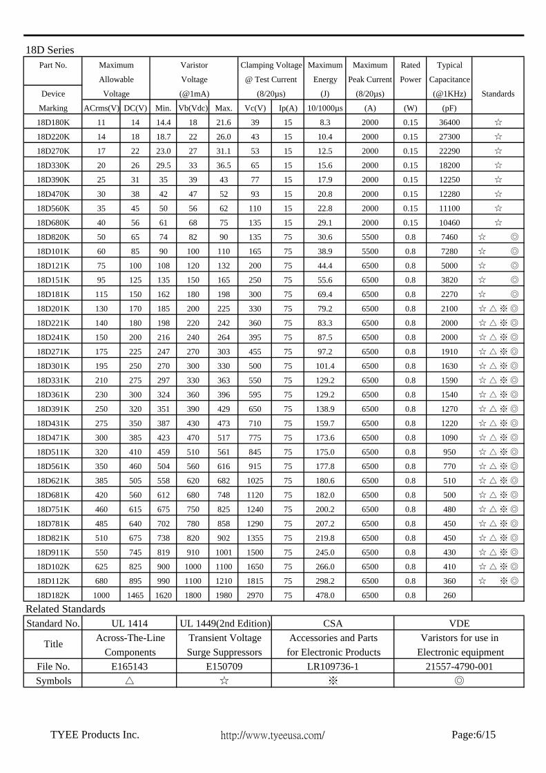
Related Standards● UL1414, UL1449(2nd Edition), CSA, VDE

Explanation of Part Numbers

05 D 2 2 0

Element Dia. Type05 ψ5.0mm D Examples K:±10%07 ψ7.0mm10 ψ10.0mm 22 × 100 = 22V special14 ψ14.0mm18 ψ18.0mm20 ψ20.0mm 22 × 101 = 220V

Varistor Voltage

requirement

Tolerance

K

or customer 2 2 0

2 2 1

TYEE Products Inc. http://www.tyeeusa.com Page : 1/15

Device Ratings and Characteristics05D Series

Part No. Maximum Maximum Rated Typical

Energy Peak Current Power Capacitance

Device (J) (8/20µs) (@1KHz) Standards

Marking ACrms(V) DC(V) Min. Vb(Vdc) Max. Vc(V) Ip(A) 10/1000µs (A) (W) (pF)

05D180K 11 14 14.4 18 21.6 44 1 0.4 100 0.01 1600 ☆

05D220K 14 18 18.7 22 26.0 51 1 0.5 100 0.01 1500 ☆

05D270K 17 22 23.0 27 31.1 60 1 0.6 100 0.01 1450 ☆

05D330K 20 26 29.5 33 36.5 73 1 0.8 100 0.01 1400 ☆

05D390K 25 31 35 39 46 86 1 0.9 100 0.01 700 ☆

05D470K 30 38 42 47 55 104 1 1.1 100 0.01 650 ☆

05D560K 35 45 50 56 66 123 1 1.3 100 0.01 600 ☆

05D680K 40 56 61 68 80 150 1 1.6 100 0.01 580 ☆

05D820K 50 65 74 82 90 145 5 2.5 400 0.10 310 ☆ ◎

05D101K 60 85 90 100 110 175 5 3.0 400 0.10 290 ☆ ◎

05D121K 75 100 108 120 132 210 5 4.0 400 0.10 270 ☆ ◎

05D151K 95 125 135 150 165 260 5 4.8 400 0.10 240 ☆ ◎

05D181K 115 150 162 180 198 325 5 5.9 400 0.10 140 ☆ ◎

05D201K 130 170 185 200 225 355 5 6.5 400 0.10 120 ☆ △ ※ ◎

05D221K 140 180 198 220 242 380 5 7.0 400 0.10 110 ☆ △ ※ ◎

05D241K 150 200 216 240 264 415 5 8.0 400 0.10 110 ☆ △ ※ ◎

05D271K 175 225 247 270 303 475 5 8.5 400 0.10 100 ☆ △ ※ ◎

05D301K 195 250 270 300 330 505 5 9.0 400 0.10 100 ☆ △ ※ ◎

05D331K 210 275 297 330 363 600 5 10.0 400 0.10 90 ☆ △ ※ ◎

05D361K 230 300 324 360 396 620 5 10.0 400 0.10 80 ☆ △ ※ ◎

05D391K 250 320 351 390 429 675 5 12.0 400 0.10 80 ☆ △ ※ ◎

05D431K 275 350 387 430 473 745 5 13.0 400 0.10 70 ☆ △ ※ ◎

05D471K 300 385 423 470 517 810 5 15.0 400 0.10 70 ☆ △ ※ ◎

05D511K 320 410 459 510 561 880 5 15.0 400 0.10 65 ☆ △ ※ ◎

05D561K 350 460 504 560 616 940 5 15.0 400 0.10 65 ☆ △ ※ ◎

05D621K 385 505 558 620 682 1050 5 15.0 400 0.10 65 ☆ △ ※ ◎

05D681K 420 560 612 680 748 1150 5 15.0 400 0.10 60 ☆ △ ※ ◎

05D751K 460 615 675 750 825 1290 5 15.0 400 0.10 60 ☆ △ ※ ◎

Standard No.

File No.Symbols

Selection guide1.Determine the necessary steady-state voltage (working voltage).2.Establish the transient energy absorbed by the varistor3.Calculate the peak transient current through the varistor4.Determine power dissipation requirement.5.Select a model to provide the required voltage-clamping characteristics

Title

Application Notes for UL Recognized ComponentsRelated Standards

VDEVaristors for use in

Electronic equipment21557-4790-001

Accessories and Partsfor Electronic Products

LR109736-1◎※

UL 1449(2nd Edition)Transient Voltage

UL 1414Across-The-Line

ComponentsE165143

Surge SuppressorsE150709

CSA

(@0.1mA) (8/20µs)

Maximum

Allowable

Voltage

Varistor Clamping Voltage

Voltage @ Test Current

TYEE Products Inc. http://www.tyeeusa.com/ Page:2/15

07D SeriesPart No. Maximum Maximum Rated Typical

Energy Peak Current Power Capacitance

Device (J) (8/20µs) (@1KHz) Standards

Marking ACrms(V) DC(V) Min. Vb(Vdc) Max. Vc(V) Ip(A) 10/1000µs (A) (W) (pF)

07D180K 11 14 14.4 18 21.6 42 2.5 0.9 250 0.02 3800 ☆

07D220K 14 18 18.7 22 26.0 47 2.5 1.1 250 0.02 3600 ☆

07D270K 17 22 23.0 27 31.1 53 2.5 1.4 250 0.02 3400 ☆

07D330K 20 26 29.5 33 36.5 65 2.5 1.7 250 0.02 2900 ☆

07D390K 25 31 35 39 43 77 2.5 2.1 250 0.02 1600 ☆

07D470K 30 38 42 47 52 93 2.5 2.5 250 0.02 1550 ☆

07D560K 35 45 50 56 62 110 2.5 3.1 250 0.02 1500 ☆

07D680K 40 56 61 68 75 135 2.5 3.6 250 0.02 1200 ☆

07D820K 50 65 74 82 90 135 10 5.5 1200 0.25 860 ☆ ◎

07D101K 60 85 90 100 110 165 10 6.5 1200 0.25 750 ☆ ◎

07D121K 75 100 108 120 132 200 10 7.8 1200 0.25 530 ☆ ◎

07D151K 95 125 135 150 165 250 10 9.7 1200 0.25 410 ☆ ◎

07D181K 115 150 162 180 198 300 10 11.7 1200 0.25 300 ☆ ◎

07D201K 130 170 185 200 225 340 10 13.0 1200 0.25 250 ☆ △ ※ ◎

07D221K 140 180 198 220 242 360 10 14.0 1200 0.25 250 ☆ △ ※ ◎

07D241K 150 200 216 240 264 395 10 15.0 1200 0.25 240 ☆ △ ※ ◎

07D271K 175 225 247 270 303 455 10 18.0 1200 0.25 220 ☆ △ ※ ◎

07D301K 195 250 270 300 330 500 10 20.0 1200 0.25 190 ☆ △ ※ ◎

07D331K 210 275 297 330 363 550 10 25.0 1200 0.25 180 ☆ △ ※ ◎

07D361K 230 300 324 360 396 595 10 25.0 1200 0.25 170 ☆ △ ※ ◎

07D391K 250 320 351 390 429 650 10 25.0 1200 0.25 160 ☆ △ ※ ◎

07D431K 275 350 387 430 473 710 10 28.0 1200 0.25 150 ☆ △ ※ ◎

07D471K 300 385 423 470 517 775 10 30.0 1200 0.25 130 ☆ △ ※ ◎

07D511K 320 410 459 510 561 845 10 30.0 1200 0.25 120 ☆ △ ※ ◎

07D561K 350 460 504 560 616 915 10 30.0 1200 0.25 120 ☆ △ ※ ◎

07D621K 385 505 558 620 682 1025 10 30.0 1200 0.25 120 ☆ △ ※ ◎

07D681K 420 560 612 680 748 1120 10 30.0 1200 0.25 110 ☆ △ ※ ◎

07D751K 460 615 675 750 825 1240 10 33.0 1200 0.25 100 ☆ △ ※ ◎

07D781K 485 640 702 780 858 1290 10 37.0 1200 0.25 90 ☆ △ ※ ◎

07D821K 510 670 738 820 902 1355 10 40.0 1200 0.25 90 ☆ △ ※ ◎

Standard No.

File No.Symbols △ ☆ ※ ◎

E165143 E150709 LR109736-1 21557-4790-001

Varistors for use inComponents Surge Suppressors for Electronic Products Electronic equipment

Title Across-The-Line Transient Voltage Accessories and Parts

Related StandardsUL 1414 UL 1449(2nd Edition) CSA VDE

Voltage

Varistor Clamping Voltage

Voltage @ Test Current

(@1mA) (8/20µs)

Maximum

Allowable

TYEE Products Inc. http://www.tyeeusa.com/ Page:3/15

10D SeriesPart No. Maximum Maximum Rated Typical

Energy Peak Current Power Capacitance

Device (J) (8/20µs) (@1KHz) Standards

Marking ACrms(V) DC(V) Min. Vb(Vdc) Max. Vc(V) Ip(A) 10/1000µs (A) (W) (pF)

10D180K 11 14 14.4 18 21.6 39 5 2.1 500 0.05 16000 ☆

10D220K 14 18 18.7 22 26.0 43 5 2.5 500 0.05 11000 ☆

10D270K 17 22 23.0 27 31.1 53 5 3.0 500 0.05 8000 ☆

10D330K 20 26 29.5 33 36.5 65 5 4.0 500 0.05 6300 ☆

10D390K 25 31 35 39 43 77 5 4.6 500 0.05 5200 ☆

10D470K 30 38 42 47 52 93 5 5.5 500 0.05 4600 ☆

10D560K 35 45 50 56 62 110 5 7.0 500 0.05 3750 ☆

10D680K 40 56 61 68 75 135 5 8.2 500 0.05 2800 ☆

10D820K 50 65 74 82 90 135 25 12.0 2500 0.40 1920 ☆ ◎

10D101K 60 85 90 100 110 165 25 15.0 2500 0.40 1800 ☆ ◎

10D121K 75 100 108 120 132 200 25 18.0 2500 0.40 1500 ☆ ◎

10D151K 95 125 135 150 165 250 25 22.0 2500 0.40 1200 ☆ ◎

10D181K 115 150 162 180 198 300 25 27.0 2500 0.40 620 ☆ ◎

10D201K 130 170 185 200 225 340 25 30.0 2500 0.40 570 ☆ △ ※ ◎

10D221K 140 180 198 220 242 360 25 32.0 2500 0.40 560 ☆ △ ※ ◎

10D241K 150 200 216 240 264 395 25 35.0 2500 0.40 550 ☆ △ ※ ◎

10D271K 175 225 247 270 303 455 25 40.0 2500 0.40 530 ☆ △ ※ ◎

10D301K 195 250 270 300 330 500 25 42.0 2500 0.40 500 ☆ △ ※ ◎

10D331K 210 275 297 330 363 550 25 47.0 2500 0.40 450 ☆ △ ※ ◎

10D361K 230 300 324 360 396 595 25 47.0 2500 0.40 450 ☆ △ ※ ◎

10D391K 250 320 351 390 429 650 25 60.0 2500 0.40 430 ☆ △ ※ ◎

10D431K 275 350 387 430 473 710 25 65.0 2500 0.40 400 ☆ △ ※ ◎

10D471K 300 385 423 470 517 775 25 70.0 2500 0.40 300 ☆ △ ※ ◎

10D511K 320 410 459 510 561 845 25 70.0 2500 0.40 260 ☆ △ ※ ◎

10D561K 350 460 504 560 616 915 25 70.0 2500 0.40 200 ☆ △ ※ ◎

10D621K 385 505 558 620 682 1025 25 70.0 2500 0.40 170 ☆ △ ※ ◎

10D681K 420 560 612 680 748 1120 25 70.0 2500 0.40 160 ☆ △ ※ ◎

10D751K 460 615 675 750 825 1240 25 75.0 2500 0.40 150 ☆ △ ※ ◎

10D781K 485 640 702 780 858 1290 25 80.0 2500 0.40 150 ☆ △ ※ ◎

10D821K 510 670 738 820 902 1355 25 85.0 2500 0.40 150 ☆ △ ※ ◎

10D911K 550 745 819 910 1001 1500 25 93.0 2500 0.40 140 ☆ △ ※ ◎

10D102K 625 825 900 1000 1100 1650 25 102.0 2500 0.40 140 ☆ △ ※ ◎

10D112K 680 895 990 1100 1210 1815 25 115.0 2500 0.40 130 ☆ ※ ◎

Standard No.

File No.Symbols △ ☆ ※ ◎

E165143 E150709 LR109736-1 21557-4790-001

Varistors for use inComponents Surge Suppressors for Electronic Products Electronic equipment

Title Across-The-Line Transient Voltage Accessories and Parts

Related StandardsUL 1414 UL 1449(2nd Edition) CSA VDE

Voltage

Clamping Voltage

@ Test Current

(8/20µs)

Varistor

Voltage

(@1mA)

Maximum

Allowable

TYEE Products Inc. http://www.tyeeusa.com/ Page:4/15

14D SeriesPart No. Maximum Maximum Rated Typical

Energy Peak Current Power Capacitance

Device (J) (8/20µs) (@1KHz) Standards

Marking ACrms(V) DC(V) Min. Vb(Vdc) Max. Vc(V) Ip(A) 10/1000µs (A) (W) (pF)

14D180K 11 14 14.4 18 21.6 39 10 4.0 1000 0.1 25000 ☆

14D220K 14 18 18.7 22 26.0 43 10 5.0 1000 0.1 20000 ☆

14D270K 17 22 23.0 27 31.1 53 10 6.0 1000 0.1 16000 ☆

14D330K 20 26 29.5 33 36.5 65 10 7.5 1000 0.1 12200 ☆

14D390K 25 31 35 39 43 77 10 8.6 1000 0.1 7000 ☆

14D470K 30 38 42 47 52 93 10 10.0 1000 0.1 6750 ☆

14D560K 35 45 50 56 62 110 10 11.0 1000 0.1 6500 ☆

14D680K 40 56 61 68 75 135 10 14.0 1000 0.1 5500 ☆

14D820K 50 65 74 82 90 135 50 22.0 4500 0.6 4300 ☆ ◎

14D101K 60 85 90 100 110 165 50 28.0 4500 0.6 3500 ☆ ◎

14D121K 75 100 108 120 132 200 50 32.0 4500 0.6 2500 ☆ ◎

14D151K 95 125 135 150 165 250 50 40.0 4500 0.6 2100 ☆ ◎

14D181K 115 150 162 180 198 300 50 50.0 4500 0.6 1250 ☆ ◎

14D201K 130 170 185 200 225 340 50 57.0 4500 0.6 1150 ☆ △ ※ ◎

14D221K 140 180 198 220 242 360 50 60.0 4500 0.6 1100 ☆ △ ※ ◎

14D241K 150 200 216 240 264 395 50 63.0 4500 0.6 1050 ☆ △ ※ ◎

14D271K 175 225 247 270 303 455 50 70.0 4500 0.6 1000 ☆ △ ※ ◎

14D301K 195 250 270 300 330 500 50 73.0 4500 0.6 900 ☆ △ ※ ◎

14D331K 210 275 297 330 363 550 50 93.0 4500 0.6 850 ☆ △ ※ ◎

14D361K 230 300 324 360 396 595 50 93.0 4500 0.6 800 ☆ △ ※ ◎

14D391K 250 320 351 390 429 650 50 100.0 4500 0.6 800 ☆ △ ※ ◎

14D431K 275 350 387 430 473 710 50 115.0 4500 0.6 650 ☆ △ ※ ◎

14D471K 300 385 423 470 517 775 50 125.0 4500 0.6 550 ☆ △ ※ ◎

14D511K 320 410 459 510 561 845 50 125.0 4500 0.6 450 ☆ △ ※ ◎

14D561K 350 460 504 560 616 915 50 125.0 4500 0.6 400 ☆ △ ※ ◎

14D621K 385 505 558 620 682 1025 50 125.0 4500 0.6 350 ☆ △ ※ ◎

14D681K 420 560 612 680 748 1120 50 130.0 4500 0.6 350 ☆ △ ※ ◎

14D751K 460 615 675 750 825 1240 50 143.0 4500 0.6 330 ☆ △ ※ ◎

14D781K 485 640 702 780 858 1290 50 148.0 4500 0.6 330 ☆ △ ※ ◎

14D821K 510 670 738 820 902 1355 50 157.0 4500 0.6 330 ☆ △ ※ ◎

14D911K 550 745 819 910 1001 1500 50 175.0 4500 0.6 300 ☆ △ ※ ◎

14D102K 625 825 900 1000 1100 1650 50 190.0 4500 0.6 300 ☆ △ ※ ◎

14D112K 680 895 990 1100 1210 1815 50 213.0 4500 0.6 200 ☆ ※ ◎

14D182K 1000 1465 1620 1800 1980 2970 50 337.0 4500 0.6 150 ☆

Standard No.

File No.Symbols △ ☆ ※ ◎

E165143 E150709 LR109736-1 21557-4790-001

Varistors for use inComponents Surge Suppressors for Electronic Products Electronic equipment

Title Across-The-Line Transient Voltage Accessories and Parts

Related StandardsUL 1414 UL 1449(2nd Edition) CSA VDE

Voltage (@1mA) (8/20µs)

Maximum Varistor Clamping Voltage

Allowable Voltage @ Test Current

TYEE Products Inc. http://www.tyeeusa.com/ Page:5/15

18D SeriesPart No. Maximum Maximum Rated Typical

Energy Peak Current Power Capacitance

Device (J) (8/20µs) (@1KHz) Standards

Marking ACrms(V) DC(V) Min. Vb(Vdc) Max. Vc(V) Ip(A) 10/1000µs (A) (W) (pF)

18D180K 11 14 14.4 18 21.6 39 15 8.3 2000 0.15 36400 ☆

18D220K 14 18 18.7 22 26.0 43 15 10.4 2000 0.15 27300 ☆

18D270K 17 22 23.0 27 31.1 53 15 12.5 2000 0.15 22290 ☆

18D330K 20 26 29.5 33 36.5 65 15 15.6 2000 0.15 18200 ☆

18D390K 25 31 35 39 43 77 15 17.9 2000 0.15 12250 ☆

18D470K 30 38 42 47 52 93 15 20.8 2000 0.15 12280 ☆

18D560K 35 45 50 56 62 110 15 22.8 2000 0.15 11100 ☆

18D680K 40 56 61 68 75 135 15 29.1 2000 0.15 10460 ☆

18D820K 50 65 74 82 90 135 75 30.6 5500 0.8 7460 ☆ ◎

18D101K 60 85 90 100 110 165 75 38.9 5500 0.8 7280 ☆ ◎

18D121K 75 100 108 120 132 200 75 44.4 6500 0.8 5000 ☆ ◎

18D151K 95 125 135 150 165 250 75 55.6 6500 0.8 3820 ☆ ◎

18D181K 115 150 162 180 198 300 75 69.4 6500 0.8 2270 ☆ ◎

18D201K 130 170 185 200 225 330 75 79.2 6500 0.8 2100 ☆ △ ※ ◎

18D221K 140 180 198 220 242 360 75 83.3 6500 0.8 2000 ☆ △ ※ ◎

18D241K 150 200 216 240 264 395 75 87.5 6500 0.8 2000 ☆ △ ※ ◎

18D271K 175 225 247 270 303 455 75 97.2 6500 0.8 1910 ☆ △ ※ ◎

18D301K 195 250 270 300 330 500 75 101.4 6500 0.8 1630 ☆ △ ※ ◎

18D331K 210 275 297 330 363 550 75 129.2 6500 0.8 1590 ☆ △ ※ ◎

18D361K 230 300 324 360 396 595 75 129.2 6500 0.8 1540 ☆ △ ※ ◎

18D391K 250 320 351 390 429 650 75 138.9 6500 0.8 1270 ☆ △ ※ ◎

18D431K 275 350 387 430 473 710 75 159.7 6500 0.8 1220 ☆ △ ※ ◎

18D471K 300 385 423 470 517 775 75 173.6 6500 0.8 1090 ☆ △ ※ ◎

18D511K 320 410 459 510 561 845 75 175.0 6500 0.8 950 ☆ △ ※ ◎

18D561K 350 460 504 560 616 915 75 177.8 6500 0.8 770 ☆ △ ※ ◎

18D621K 385 505 558 620 682 1025 75 180.6 6500 0.8 510 ☆ △ ※ ◎

18D681K 420 560 612 680 748 1120 75 182.0 6500 0.8 500 ☆ △ ※ ◎

18D751K 460 615 675 750 825 1240 75 200.2 6500 0.8 480 ☆ △ ※ ◎

18D781K 485 640 702 780 858 1290 75 207.2 6500 0.8 450 ☆ △ ※ ◎

18D821K 510 675 738 820 902 1355 75 219.8 6500 0.8 450 ☆ △ ※ ◎

18D911K 550 745 819 910 1001 1500 75 245.0 6500 0.8 430 ☆ △ ※ ◎

18D102K 625 825 900 1000 1100 1650 75 266.0 6500 0.8 410 ☆ △ ※ ◎

18D112K 680 895 990 1100 1210 1815 75 298.2 6500 0.8 360 ☆ ※ ◎

18D182K 1000 1465 1620 1800 1980 2970 75 478.0 6500 0.8 260

Standard No.

File No.Symbols △ ☆ ※ ◎

E165143 E150709 LR109736-1 21557-4790-001

Varistors for use inComponents Surge Suppressors for Electronic Products Electronic equipment

Title Across-The-Line Transient Voltage Accessories and Parts

Related StandardsUL 1414 UL 1449(2nd Edition) CSA VDE

Voltage (@1mA) (8/20µs)

Maximum Varistor Clamping Voltage

Allowable Voltage @ Test Current

TYEE Products Inc. http://www.tyeeusa.com/ Page:6/15

20D SeriesPart No. Maximum Maximum Rated Typical

Energy Peak Current Power Capacitance

Device (J) (8/20µs) (@1KHz) Standards

Marking ACrms(V) DC(V) Min. Vb(Vdc) Max. Vc(V) Ip(A) 10/1000µs (A) (W) (pF)

20D180K 11 14 14.4 18 21.6 39 20 11.0 2000 0.2 40000 ☆

20D220K 14 18 18.7 22 26.0 43 20 14.0 2000 0.2 30000 ☆

20D270K 17 22 23.0 27 31.1 53 20 18.0 2000 0.2 24500 ☆

20D330K 20 26 29.5 33 36.5 65 20 23.0 2000 0.2 20000 ☆

20D390K 25 31 35 39 43 77 20 26.0 2000 0.2 13800 ☆

20D470K 30 38 42 47 52 93 20 33.0 2000 0.2 13500 ☆

20D560K 35 45 50 56 62 110 20 41.0 2000 0.2 12200 ☆

20D680K 40 56 61 68 75 135 20 46.0 2000 0.2 11500 ☆

20D820K 50 65 74 82 90 135 100 38.0 6500 1.0 8200 ☆ ◎

20D101K 60 85 90 100 110 165 100 45.0 6500 1.0 8000 ☆ ◎

20D121K 75 100 108 120 132 200 100 55.0 6500 1.0 5500 ☆ ◎

20D151K 95 125 135 150 165 250 100 70.0 6500 1.0 4200 ☆ ◎

20D181K 115 150 162 180 198 300 100 85.0 6500 1.0 2500 ☆ ◎

20D201K 130 170 185 200 225 340 100 95.0 6500 1.0 2300 ☆ △ ※ ◎

20D221K 140 180 198 220 242 360 100 100.0 6500 1.0 2200 ☆ △ ※ ◎

20D241K 150 200 216 240 264 395 100 108.0 6500 1.0 2200 ☆ △ ※ ◎

20D271K 175 225 247 270 303 455 100 127.0 6500 1.0 2100 ☆ △ ※ ◎

20D301K 195 250 270 300 330 500 100 150.0 6500 1.0 1800 ☆ △ ※ ◎

20D331K 210 275 297 330 363 550 100 163.0 6500 1.0 1750 ☆ △ ※ ◎

20D361K 230 300 324 360 396 595 100 163.0 6500 1.0 1700 ☆ △ ※ ◎

20D391K 250 320 351 390 429 650 100 180.0 6500 1.0 1400 ☆ △ ※ ◎

20D431K 275 350 387 430 473 710 100 190.0 6500 1.0 1350 ☆ △ ※ ◎

20D471K 300 385 423 470 517 775 100 220.0 6500 1.0 1200 ☆ △ ※ ◎

20D511K 320 410 459 510 561 845 100 220.0 6500 1.0 1050 ☆ △ ※ ◎

20D561K 350 460 504 560 616 915 100 220.0 6500 1.0 850 ☆ △ ※ ◎

20D621K 385 505 558 620 682 1025 100 220.0 6500 1.0 570 ☆ △ ※ ◎

20D681K 420 560 612 680 748 1120 100 230.0 6500 1.0 550 ☆ △ ※ ◎

20D751K 460 615 675 750 825 1240 100 255.0 6500 1.0 530 ☆ △ ※ ◎

20D781K 485 640 702 780 858 1290 100 265.0 6500 1.0 500 ☆ △ ※ ◎

20D821K 510 675 738 820 902 1355 100 282.0 6500 1.0 500 ☆ △ ※ ◎

20D911K 550 745 819 910 1001 1500 100 310.0 6500 1.0 480 ☆ △ ※ ◎

20D102K 625 825 900 1000 1100 1650 100 342.0 6500 1.0 460 ☆ △ ※ ◎

20D112K 680 895 990 1100 1210 1815 100 383.0 6500 1.0 400 ☆ ※ ◎

20D182K 1000 1465 1620 1800 1980 2970 100 625.0 6500 1.0 250

Standard No.

File No.Symbols △ ☆ ※ ◎

E165143 E150709 LR109736-1 21557-4790-001

Varistors for use inComponents Surge Suppressors for Electronic Products Electronic equipment

Title Across-The-Line Transient Voltage Accessories and Parts

Related StandardsUL 1414 UL 1449(2nd Edition) CSA VDE

Voltage (@1mA) (8/20µs)

Maximum Varistor Clamping Voltage

Allowable Voltage @ Test Current

TYEE Products Inc. http://www.tyeeusa.com/ Page:7/15

Dimension Table Unit:mm Model

Symbol

D(max.) 7.5 9.0 14.0 17.5 23.0 25.0 H(max.) 10.0 12.0 17.0 20.5 26.0 28.0 W(±1.0) 5.0 5.0 7.5 7.5 7.5 10.0L(min.) 25.0 25.0 25.0 25.0 25.0 25.0

d(±0.02) 0.6 0.6 0.8 0.8 0.8 1.0

T(max). Table Unit:mmPart No 05D 07D 10D 14D 18D 20D Part No 05D 07D 10D 14D 18D 20D

180K 3.3 3.5 3.9 4.0 4.2 4.3 301K 3.9 4.1 4.3 4.4 4.6 4.7220K 3.6 3.8 4.2 4.3 4.5 4.6 331K 4.0 4.2 4.5 4.6 4.8 4.9270K 3.8 4.0 4.4 4.5 4.7 4.8 361K 4.1 4.3 4.7 4.8 5.0 5.1330K 3.3 3.5 3.9 4.0 4.2 4.3 391K 4.2 4.4 4.8 4.9 5.1 5.2390K 3.5 3.7 4.1 4.2 4.4 4.5 431K 4.4 4.6 5.0 5.1 5.3 5.4470K 3.7 3.9 4.3 4.4 4.6 4.7 471K 4.6 4.8 5.2 5.3 5.5 5.6560K 4.0 4.2 4.6 4.7 4.9 5.0 511K 4.8 5.0 5.3 5.4 5.6 5.7680K 4.3 4.5 4.9 5.0 5.2 5.3 561K 5.0 5.2 5.5 5.6 5.7 5.9820K 3.3 3.5 3.9 4.0 4.2 4.3 621K 5.3 5.5 5.7 5.8 6.0 6.1101K 3.6 3.8 4.2 4.3 4.5 4.6 681K 5.4 5.6 5.8 5.9 6.1 6.2121K 3.8 4.0 4.4 4.5 4.7 4.8 751K 5.6 5.8 6.0 6.1 6.3 6.4151K 4.1 4.3 4.7 4.8 5.0 5.1 781K 5.8 6.0 6.3 6.4 6.6 6.7181K 3.2 3.4 3.8 3.9 4.1 4.2 821K x 6.3 6.5 6.6 6.8 6.9201K 3.3 3.5 3.9 4.0 4.2 4.3 911K x x 6.6 6.7 6.9 7.0221K 3.4 3.6 4.0 4.1 4.3 4.4 102K x x 7.0 7.1 7.3 7.4241K 3.5 3.7 4.1 4.2 4.4 4.5 112K x x 7.4 7.5 7.7 7.9271K 3.7 3.9 4.2 4.3 4.5 4.6 182K x x x 11.5 11.7 11.9

Packing Quantity

20002000

200001000060004000

10000500030002000

10001000500500

Min. Q'ty(pcs) /CartonPart No. Min. Q'ty(pcs)

/ BagsMin. Q'ty(pcs)

/Inner Box

250250

10001000

14DXXXK18DXXXK20DXXXK

05DXXXK07DXXXK10DXXXK

Dimension of Standard Products

18D 20D05D 07D 10D 14D

TYEE Products Inc. http://www.tyeeusa.com/ Page:8/15

Crimped Lead Type

Unit:mmSeries

Symbol

A max. Varistor Voltage 18V to 330V 13.0 15.0 19.5 22.5 30.5

V1mA(V) 360V to 1800V 13.0 15.0 20.5 23.5 32.0

Dmax. 7.5 9.0 14.0 17.5 25.0

K 1.2±0.4 1.2±0.4 1.4±0.4 1.4±0.4 1.6±0.4

W 5.0±1.0 5.0±1.0 7.5±1.0 7.5±1.0 10.0±1.0

CL 5.0±0.5 5.0±0.5 5.0±0.5 5.0±0.5 5.0±0.5

φd 0.6 0.6 0.8 0.8 1.0Symbol T : Product thickness please refer to dimension of standard products

Packing QuantityCut-off

Type I LeadCut-off

Type II LeadCut-off

Type III LeadMin. Q'ty (pcs)/Bags

Min. Q'ty (pcs)/Inner Box

Min. Q'ty (pcs)/Carton

-TTK -TTI -TTH 1000 15000 30000

-TTK -TTI -TTH 1000 15000 30000

-TTK -TTI -TTH 500 5000 10000

-TTK -TTI -TTH 500 3000 6000

N/A N/A N/A 250 1500 3000

N/A N/A N/A 250 1500 3000

Type IIIType IIType I

05D Series 07D Series 10D Series 14D Series 20D Series

20DXXXK-TTS

10DXXXK-TTS

14DXXXK-TTS

18DXXXK-TTS

Cut-off Straight Lead

05DXXXK-TTS

07DXXXK-TTS

TYEE Products Inc. http://www.tyeeusa.com/ Page:9/15

Tape and Reel Fig.

05D、07D Type I Lead FIG 1 05D、07D Straight Lead FIG 2

10D Type I Lead FIG 3 FIG 4

14D Type I Lead FIG 5 14D Straight Lead FIG 6Taping product ordering Information

-TRK -TRI -TRH -BTK -BTI -BTH-TRK -TRI -TRH -BTK -BTI -BTH-TRK -TRI -TRH -BTK -BTI -BTH-TRK -TRI -TRH OUTSIDE INSIDE CRIMPED

OUTSIDE INSIDE CRIMPED KINK KINKKINK KINK

10D Straight Lead

10DXXXK-TRS14DXXXK-TRS

Striaght LeadStriaght Lead Type I Lead Type II Lead

Type III Lead

05DXXXK-TRS 05DXXXK-BTS

Type III Lead

Tape & Reel Flax Box

07DXXXK-TRS

Type I Lead Type II Lead

07DXXXK-BTS10DXXXK-BTS

TYEE Products Inc. http://www.tyeeusa.com/ Page:10/15

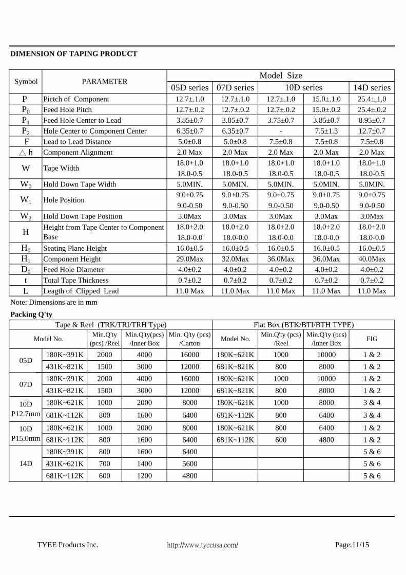
05D series 07D series 14D seriesP Pictch of Component 12.7±.1.0 12.7±.1.0 12.7±.1.0 15.0±.1.0 25.4±.1.0P0 Feed Hole Pitch 12.7±.0.2 12.7±.0.2 12.7±.0.2 15.0±.0.2 25.4±.0.2P1 Feed Hole Center to Lead 3.85±0.7 3.85±0.7 3.75±0.7 3.85±0.7 8.95±0.7P2 Hole Center to Component Center 6.35±0.7 6.35±0.7 - 7.5±1.3 12.7±0.7 F Lead to Lead Distance 5.0±0.8 5.0±0.8 7.5±0.8 7.5±0.8 7.5±0.8△ h Component Alignment 2.0 Max 2.0 Max 2.0 Max 2.0 Max 2.0 Max

18.0+1.0 18.0+1.0 18.0+1.0 18.0+1.0 18.0+1.018.0-0.5 18.0-0.5 18.0-0.5 18.0-0.5 18.0-0.5

W0 Hold Down Tape Width 5.0MIN. 5.0MIN. 5.0MIN. 5.0MIN. 5.0MIN.9.0+0.75 9.0+0.75 9.0+0.75 9.0+0.75 9.0+0.759.0-0.50 9.0-0.50 9.0-0.50 9.0-0.50 9.0-0.50

W2 Hold Down Tape Position 3.0Max 3.0Max 3.0Max 3.0Max 3.0Max18.0+2.0 18.0+2.0 18.0+2.0 18.0+2.0 18.0+2.018.0-0.0 18.0-0.0 18.0-0.0 18.0-0.0 18.0-0.0

H0 Seating Plane Height 16.0±0.5 16.0±0.5 16.0±0.5 16.0±0.5 16.0±0.5H1 Component Height 29.0Max 32.0Max 36.0Max 36.0Max 40.0MaxD0 Feed Hole Diameter 4.0±0.2 4.0±0.2 4.0±0.2 4.0±0.2 4.0±0.2t Total Tape Thickness 0.7±0.2 0.7±0.2 0.7±0.2 0.7±0.2 0.7±0.2L Leagth of Clipped Lead 11.0 Max 11.0 Max 11.0 Max 11.0 Max 11.0 Max

Note: Dimensions are in mmPacking Q'ty

180K~391K 2000 4000 16000 180K~621K 1000 10000 1 & 2431K~821K 1500 3000 12000 681K~821K 800 8000 1 & 2180K~391K 2000 4000 16000 180K~621K 1000 10000 1 & 2431K~821K 1500 3000 12000 681K~821K 800 8000 1 & 2180K~621K 1000 2000 8000 180K~621K 1000 8000 3 & 4

681K~112K 800 1600 6400 681K~112K 800 6400 3 & 4

180K~621K 1000 2000 8000 180K~621K 800 6400 1 & 2681K~112K 800 1600 6400 681K~112K 600 4800 1 & 2180K~391K 800 1600 6400 5 & 6431K~621K 700 1400 5600 5 & 6681K~112K 600 1200 4800 5 & 6

Symbol PARAMETERModel Size

10D series

Height from Tape Center to Component Base

Tape & Reel (TRK/TRI/TRH Type) Flat Box (BTK/BTI/BTH TYPE)

W Tape Width

W1 Hole Position

10D P12.7mm

14D

05D

07D

10D P15.0mm

Min.Q'ty (pcs) /Reel

Min.Q'ty (pcs) /Inner Box FIG

DIMENSION OF TAPING PRODUCT

Model No. Model No.Min.Q'ty (pcs) /Reel

Min.Q'ty(pcs) /Inner Box

Min. Q'ty (pcs) /Carton

H

TYEE Products Inc. http://www.tyeeusa.com/ Page:11/15
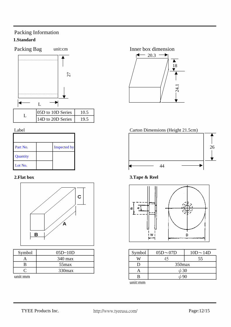
1.Standard

Packing Bag unit:cm Inner box dimension

05D to 10D Series 10.514D to 20D Series 19.5

Label Carton Dimensions (Height 21.5cm)

Part No. Inspected by

Quantity

Lot No.

2.Flat box 3.Tape & Reel

Symbol SymbolA WB DC A

unit:mm Bunit:mm

ψ90

05D~07D 10D~14D5545

L

Packing Information

350maxψ30

05D~10D340 max55max

330max

20.3

24.1

18

L

27

44

26

TYEE Products Inc. http://www.tyeeusa.com/ Page:12/15

Performance Characteristics(Electrical)

Classification ( Nominal varistor voltage )

Test Voltage ( AC )

V0.1 mA, V1 mA ≦330V 1000 Vrms

V0.1 mA, V1 mA >330V 1500 Vrms

05D180K to 05D680K 0.5A (2 ms)05D820K to 05D471K 20A (8/20μs)07D180K to 07D680K 18A (8/20μs)07D820K to 07D471K 50A (8/20μs)10D180K to 10D680K 50A (8/20μs)10D820K to 10D112K 100A (8/20μs)14D180K to 14D680K 75A (8/20μs)14D820K to 14D182K 150A (8/20μs)20D180K to 20D680K 120A (8/20μs)20D820K to 20D182K 200A (8/20μs)

Characteristics Test Methods/Description Specifications

Standard Test ConditionEnvironmental conditions under which every measuring is done without doubt on the measuring results. Unless specially specified, temperature, relative humidity are 5 to 35 ℃, 45 to 85 % RH.

Varistor VoltageThe voltage between two terminals with the specified measuring current CmA DC applied is called Vc or VcmA . The measurement shall be made as fast as possible to avoid heat affection.

To meet the specified value

Maximum Allowable Voltage The maximum sinusoidal RMS voltage or maximum DC voltage that can be applied continuously in the specified environmental temperature range.

Clamping Voltage

The maximum voltage between two terminals with the specified standard impulse current (8/20μs) illustrated below applied.

Rated Power The power that can be applied in the specified ambient temperature.

Maximum EnergyThe maximum energy within the varistor voltage change of ± 10 % when one impulse of 2 ms or 10/1000 μs is applied.

Maximum peak Current Withstanding

Surge Current

2 timesThe maximum current within the varistor voltage change of ± 10 % with the standard impulse current (8/20μs) applied two times with an interval of 5 minutes.

1 timesThe maximum current within the varistor voltage change of ± 10 % with the standard impulse current (8/20μs) applied one times.

Temperature Coefficient of Varistor Voltage × × 100 ( %/ ℃ ) - 0.05 %/℃ max

CapacitanceCapacitance shall be measured at 1 KHz ± 10 %, 1Vrms max . 0V bias and 20±2℃

To meet the specified value

Withstanding Voltage ( Body Insulation )

The specified voltage shall be applied both terminals of the specimen connected together and metal foil closely wrapped round its body for 1 minute. Electrical breakdown shall be examined.

No breakdown

Impulse Life(I)

The change of Vc shall be measured after the impulse listed below is applied 10000 times continuously with the interval of ten seconds at room temperature .

△VcmA / VcmA≦±10%

5 Series

7 Series

20 Series

Note: Varistor voltage change of forward direction shall be measured in the test of uni-pole surge life and DC load life

10 Series

14 Series

Vc at 85 ℃ ─ Vc at 25 ℃

Vc at 25 ℃

160

TYEE Products Inc. http://www.tyeeusa.com/ Page: 13/15

(Electrical)

05D180K to 05D680K 0.45A (2 ms)05D820K to 05D471K 14A (8/20μs)07D180K to 07D680K 12A (8/20μs)07D820K to 07D471K 35A (8/20μs)10D180K to 10D680K 35A (8/20μs)10D820K to 10D471K 70A (8/20μs)14D180K to 14D680K 45A (8/20μs)14D820K to 14D471K 90A (8/20μs)20D180K to 20D680K 55A (8/20μs)20D820K to 20D471K 100A (8/20μs)

(Mechanical)

Approximately 95% of the terminals shall becovered with solder uni-formly

Resistance to Soldering Heat

After each lead shall be dipped into a solder bath having a temperature 260±5℃ (3 series: 250±5℃) to a point 2.0 to 2.5 mm from the body of the unit, using shieldig board (t=1.5mm), be held there for specified time (3series: 3±1 s, 5 series: 5±1 s and others: 10±1 s ), and then be stored at room temperature and humidity for 1 to 2 hours. The change of Vc and mechanical damages are examined.

△VcmA/VcmA≦±5%No outstandingdamage

Vibration

After repeadly applying a single harmonic vibration (amplitude: 0.75 mm) double amplitude:1.5mm with 1 minute vibration frequency cycles (10 Hz to 55 Hz to 10 Hz) to each of three perpendicular directions for 2 hours. Thereafter, the unit shall be visually examined.

SolderadiltyAfter dipping the terminals to a depth of approximately 3mm from the body in a soldering bath of 235±5℃ for 2±0.5 seconds, the terminal shall be visually examined.

Robustness of Terminations (Bending)

The unit shall be secured with its terminal kept vertical and the force specified below be applied in the axial direction.

The terminal shall gradually be bent by 90° in one direction, then 90°in the opposite direction, and again back to the original position.

The damage of the terminal shall be visually examined. Terminal diameter Force Ø 0.6 mm 4.9 N (0.5Kgf) Ø 0.8 mm 4.9 N (0.5Kgf) Ø 1.0 mm 9.8 N (1.0Kgf)

Characteristics Test Methods Specifications

Robustness of Terminations (Tensile)

After gradually applying the force specified below and keeping the unit fixed for the seconds, the terminal shall be visually examined for any damage.

No outstanding damage

Terminal diameter Force Ø 0.6 mm 9.8 N (1.0Kgf) Ø 0.8 mm 9.8 N (1.0Kgf) Ø 1.0 mm 19.6 N (2.0Kgf)

20 Series

Note: Varistor voltage change of forward direction shall be measured in the test of uni-pole surge life and DC load life

10 Series

14 Series

Characteristics Test Methods Specifications

Impulse Life(II)

The change of Vc shall be measured after the impulse listed below is applied 100000 times continuously with the interval of ten seconds at room temperature .

△VcmA/VcmA≦±10%

5 Series

7 Series

TYEE Products Inc. http://www.tyeeusa.com/ Page:14/15
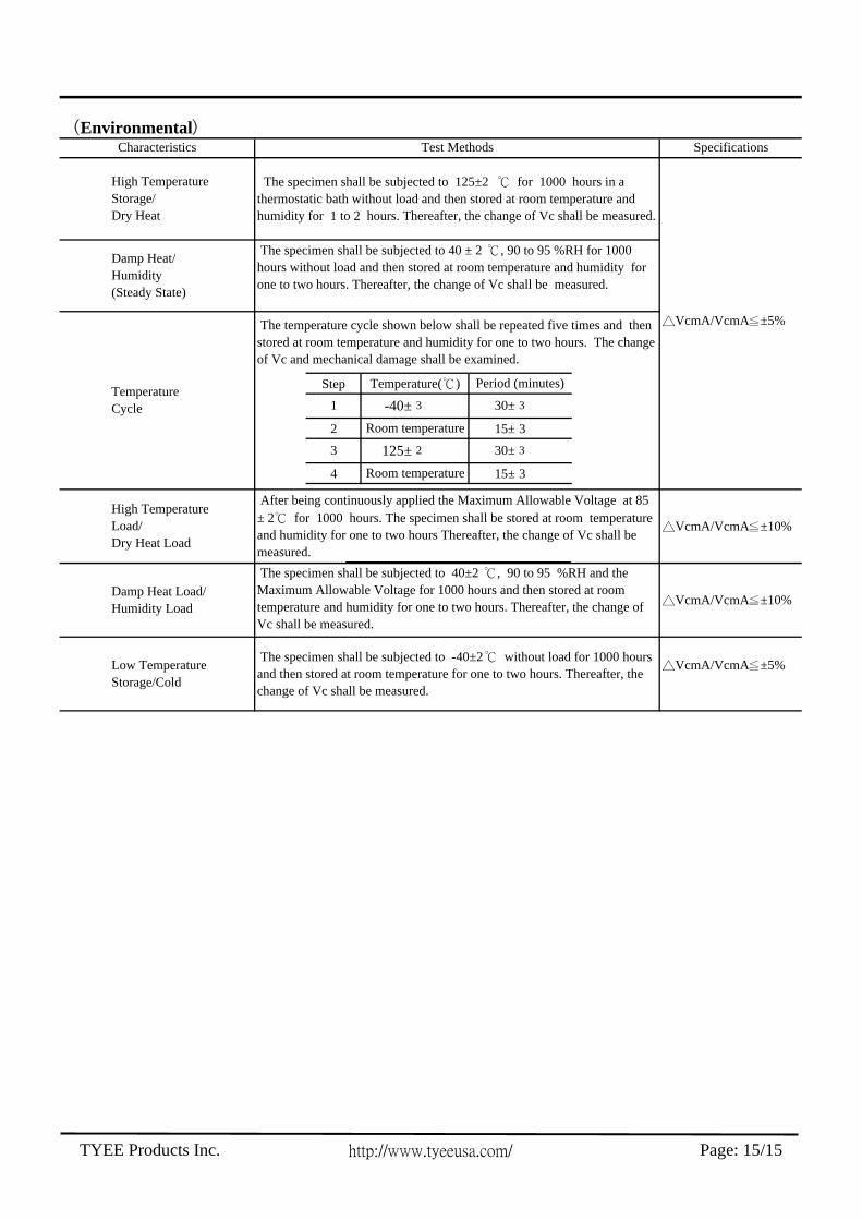
(Environmental)

Step

2 15± 3

4 15± 3

Characteristics Test Methods Specifications

High Temperature Storage/ Dry Heat

The specimen shall be subjected to 125±2 ℃ for 1000 hours in a thermostatic bath without load and then stored at room temperature and humidity for 1 to 2 hours. Thereafter, the change of Vc shall be measured.

△VcmA/VcmA≦±5%

Damp Heat/ Humidity (Steady State)

The specimen shall be subjected to 40 ± 2 ℃, 90 to 95 %RH for 1000 hours without load and then stored at room temperature and humidity for one to two hours. Thereafter, the change of Vc shall be measured.

Temperature Cycle

The temperature cycle shown below shall be repeated five times and then stored at room temperature and humidity for one to two hours. The change of Vc and mechanical damage shall be examined.

Temperature(℃) Period (minutes)

1 -40± 3 30± 3

Room temperature

3 125± 2 30± 3

Room temperature

High Temperature Load/ Dry Heat Load

After being continuously applied the Maximum Allowable Voltage at 85 ± 2℃ for 1000 hours. The specimen shall be stored at room temperature and humidity for one to two hours Thereafter, the change of Vc shall be measured.

Low Temperature Storage/Cold

The specimen shall be subjected to -40±2℃ without load for 1000 hours and then stored at room temperature for one to two hours. Thereafter, the change of Vc shall be measured.

△VcmA/VcmA≦±5%

△VcmA/VcmA≦±10%

Damp Heat Load/ Humidity Load

The specimen shall be subjected to 40±2 ℃, 90 to 95 %RH and the Maximum Allowable Voltage for 1000 hours and then stored at room temperature and humidity for one to two hours. Thereafter, the change of Vc shall be measured.

△VcmA/VcmA≦±10%

TYEE Products Inc. http://www.tyeeusa.com/ Page: 15/15


Recommended