VASE: Filtering IP spoofing traffic with agility Guang Yao ⇑ , Jun Bi, Peiyao Xiao Tsinghua University, FIT Building Room 4-204, Beijing 100084, China article info Article history: Received 8 November 2011 Received in revised form 24 May 2012 Accepted 9 August 2012 Available online 21 September 2012 Keywords: TCP/IP IP spoofing Agility abstract Filtering out traffic with forged source address on routers can significantly improve the security of Internet. However, despite intermittent IP spoofing attacks, existing filtering mechanisms inspect each packet all the time, consuming considerable resource on routers even there is no spoofing at all. This article considers the requirement for a solution performing IP spoofing filtering with agility, which consumes resource in proportional to the size of attack. A novel IP spoofing filtering mechanism named Virtual Anti-Spoofing Edge (VASE) is proposed in this article. VASE uses sampling and on-demand filter configu- ration to reduce unnecessary overhead in peace time. The evaluation based on simulation shows VASE has obvious advantages over commonly used mechanisms in various scenar- ios. VASE is fully compatible with current IP spoofing filtering practices and can be imple- mented with commodity routers. In the campus network of Tsinghua University, VASE is providing real benefits. Ó 2012 Elsevier B.V. All rights reserved. 1. Introduction IP spoofing [1], which means attackers make use of forged source IP addresses to launch attacks, has been long recognized as a serious security problem on the Internet. By modifying the source address of attacking traffic to address assigned to others or even unassigned, an attacker can hide its actual location, or circumvent access control rules on source, or utilize the flaw of the victim system, or gain the capability of launching reflection based attack. A number of notorious attacks rely on IP spoofing, includ- ing SYN flooding [2], Smurf [3], DNS amplification [4], etc. In 2006, a DNS amplification attack against Top Level Domain (TLD) name server severely degraded the capacity of the TLD name server for several days [5]. According to the observation of CAIDA, there are at least 3000 (D)DoS attacks based on IP spoofing in a week [6]. In the NANOG 50th meeting, a presentation from ARBOR shows spoofing is quite significant in despite of large size of zombie networks [7]. To filter IP spoofing traffic, Internet Service Providers (ISPs) generally deploy filtering mechanisms on routers to perform prefix granularity filtering, i.e., Ingress/Egress Filtering [8]. The measurement from MIT Spoofer project [9] shows Ingress Filtering (or similar mechanisms) has been deployed on 76.2% ASs of all the participants. The statistic work of ARBOR Networks shows Ingress Filtering has been deployed on approaching 60% ISP networks investigated [10]. uRPF [11] is the most common approach to implement Ingress Filtering. It filters the packet based on looking up in the forwarding table to check whether the incoming interface of a packet matches the forwarding interface to the source. However, due to the requirement of robustness and load-balance, the Internet network path is becoming more and more diversified and asymmetric. uRPF will drop legitimate traffic whenever the incoming interface is not exactly the forwarding interface resulting from asymmetric routing. In the real deployment, uRPF is only used on the access port of the edge network. Such deployment does not have defense capability against spoofing traffic from undeployed networks or other do- mains. The other way to implement Ingress Filtering is using Access Control List (ACL). Whenever ACL is 1389-1286/$ - see front matter Ó 2012 Elsevier B.V. All rights reserved. http://dx.doi.org/10.1016/j.comnet.2012.08.018 ⇑ Corresponding author. Tel./fax: +86 010 62795818x6948. E-mail address: [email protected](G. Yao). Computer Networks 57 (2013) 243–257 Contents lists available at SciVerse ScienceDirect Computer Networks journal homepage: www.elsevier.com/locate/comnet
Transcript
Computer Networks 57 (2013) 243–257
Contents lists available at SciVerse ScienceDirect
Guang Yao ⇑, Jun Bi, Peiyao XiaoTsinghua University, FIT Building Room 4-204, Beijing 100084, China
a r t i c l e i n f o
Article history:Received 8 November 2011Received in revised form 24 May 2012Accepted 9 August 2012Available online 21 September 2012
Keywords:TCP/IPIP spoofingAgility
1389-1286/$ - see front matter � 2012 Elsevier B.Vhttp://dx.doi.org/10.1016/j.comnet.2012.08.018
⇑ Corresponding author. Tel./fax: +86 010 627958E-mail address: [email protected] (G. Y
a b s t r a c t
Filtering out traffic with forged source address on routers can significantly improve thesecurity of Internet. However, despite intermittent IP spoofing attacks, existing filteringmechanisms inspect each packet all the time, consuming considerable resource on routerseven there is no spoofing at all. This article considers the requirement for a solutionperforming IP spoofing filtering with agility, which consumes resource in proportional tothe size of attack. A novel IP spoofing filtering mechanism named Virtual Anti-SpoofingEdge (VASE) is proposed in this article. VASE uses sampling and on-demand filter configu-ration to reduce unnecessary overhead in peace time. The evaluation based on simulationshows VASE has obvious advantages over commonly used mechanisms in various scenar-ios. VASE is fully compatible with current IP spoofing filtering practices and can be imple-mented with commodity routers. In the campus network of Tsinghua University, VASE isproviding real benefits.
� 2012 Elsevier B.V. All rights reserved.
1. Introduction
IP spoofing [1], which means attackers make use offorged source IP addresses to launch attacks, has been longrecognized as a serious security problem on the Internet.By modifying the source address of attacking traffic toaddress assigned to others or even unassigned, an attackercan hide its actual location, or circumvent access controlrules on source, or utilize the flaw of the victim system,or gain the capability of launching reflection based attack.A number of notorious attacks rely on IP spoofing, includ-ing SYN flooding [2], Smurf [3], DNS amplification [4], etc.In 2006, a DNS amplification attack against Top LevelDomain (TLD) name server severely degraded the capacityof the TLD name server for several days [5]. According tothe observation of CAIDA, there are at least 3000 (D)DoSattacks based on IP spoofing in a week [6]. In the NANOG50th meeting, a presentation from ARBOR shows spoofingis quite significant in despite of large size of zombienetworks [7].
. All rights reserved.
18x6948.ao).
To filter IP spoofing traffic, Internet Service Providers(ISPs) generally deploy filtering mechanisms on routersto perform prefix granularity filtering, i.e., Ingress/EgressFiltering [8]. The measurement from MIT Spoofer project[9] shows Ingress Filtering (or similar mechanisms) hasbeen deployed on 76.2% ASs of all the participants. Thestatistic work of ARBOR Networks shows Ingress Filteringhas been deployed on approaching 60% ISP networksinvestigated [10]. uRPF [11] is the most common approachto implement Ingress Filtering. It filters the packet basedon looking up in the forwarding table to check whetherthe incoming interface of a packet matches the forwardinginterface to the source. However, due to the requirementof robustness and load-balance, the Internet network pathis becoming more and more diversified and asymmetric.uRPF will drop legitimate traffic whenever the incominginterface is not exactly the forwarding interface resultingfrom asymmetric routing. In the real deployment, uRPF isonly used on the access port of the edge network. Suchdeployment does not have defense capability againstspoofing traffic from undeployed networks or other do-mains. The other way to implement Ingress Filtering isusing Access Control List (ACL). Whenever ACL is
244 G. Yao et al. / Computer Networks 57 (2013) 243–257
processed by the processor of the router, the router mustscan the ACL entries until finding a match. It is known suchACL will degrade the performance of the router greatly,especially whenever the network load is heavy [12].Though packet inspection with TCAM (Ternary ContentAddressable Memory) based ACL can be performed at linespeed, TCAM is expensive and limited resource on routers,shared by routing, QoS and other functions requiring IPlooking-up. Unfortunately, the explosion of route entrieshas made a large number of routers just load all the routeentries [13]. The required TCAM resource in a spoofing fil-tering mechanism is determined by the filtering granular-ity. Prefix granularity IP spoofing filtering on routers willcost at least the same amount TCAM entries of the routingfunction, because it must map each prefix to the corre-sponding incoming interface, just as the routing functionmust map each prefix to the corresponding forwardinginterface.
There are also other proposed spoofing filtering mecha-nisms, which are generally classified into filtering-on-path[14–17] and end-to-end authentication [18,19]. Till nowno mechanism is known to obtain better data plane pro-cessing performance and less resource consumption thanTCAM based ACL. In these mechanisms, other than the dataplane cost, control plane also generates unnecessary costwhen no spoofing happens. Take route based mechanismas an example, whenever route changes, the filtering ruleson routers must be reconstructed just to avoid discardinglegitimate packet even there is no spoofing at all [15].
Despite the processing overhead on all packets and per-manent occupied resource, there is not always spoofingbased attack in the network. IP spoofing is typically usedto launch DDoS attack, which is generally short and fierce.According to the analysis of CAIDA [6], 80% attacks are lessthan 30 min, but only 1% attacks are more than 10 h. In along period, the ratio of spoofing traffic is trivial to legiti-mate traffic; however, to filter out the spoofing traffic,the load of the router is significantly increased all the time.
Though serious resource waste exists in current anti-spoofing mechanisms, there has been no solution knownto reduce the waste. In authors’ opinion, the key factor toreduce the waste is to perform filtering with agility. In thisarticle, a novel spoofing IP flow filtering mechanism namedVirtual Anti-Spoofing Edge (VASE) is proposed to provideagile IP spoofing filtering capability. It minimizes the dataplane cost when no spoofing happens and provides maxi-mum filtering capability whenever spoofing is detected.VASE forms a protective perimeter which protects insidenodes from spoofing from the outside. Routers on theperimeter perform sampling but do not check each packet.The samples are redirected to the VASE server whichcaptures and analyses the samples. Instead of deploying al-ways configured filters on routers, VASE adaptively config-ures filters on routers in attack and removes filters if nospoofing is detected. A novel filter generation mechanismis designed to help identify spoofing packet. Though simu-lation, we found VASE can greatly reduce the resourcerequirement on routers without reducing filtering ability.VASE is fully compatible with existing commercial routers,and it has been deployed in the campus network of Tsing-hua University for almost a year.
This work is of following contributions:
� It is the first work known concerning the unnecessarycost of existing IP spoofing filtering mechanisms. Thereis not always spoofing traffic in the network. Even whenthere is a spoofing attack, it is usually of no need to con-figure all the filtering rules on routers. Always-and-allconfigured filtering rules introduce significant overheadon routers and may cause discarding legitimate trafficin case of route change. It proposes the object thatspoofing filtering must be performed with agility.� It proposes a solution, VASE, which enables IP spoofing
filtering with agility. VASE configures filtering rules onthe router on-demand to avoid unnecessary cost onthe routers when there is no spoofing traffic. On-demand filtering rule generation mechanism is usedto reduce the overhead of control plane. Through makeuse of the existing interfaces of current routers, VASE isfully compatible with current commercial routers and iseasy to deploy in the real network.� VASE has been deployed in real IPv6 networks for
around one year. It has captured quite a large numberof IP address misuses from a private 6to4 tunnel inreality. Excluding the misuses, over the last year, VASEserver only configured one rule hundreds of times onone router to filter spoofing caused by a controversialconfiguration error. The deployment proves VASE is afeasible solution to avoid unnecessary cost in peacetime.
The following of this article is structured as follows. Thefollowing section is the detailed description of the VASEarchitecture. Then we evaluate VASE through simulationand analyze the result of the simulation. An implementa-tion of VASE and its real deployment is introduced in thefollowing section. Then main IP spoofing prevention mech-anisms are summarized. The interfaces of commodity rou-ters used by VASE are introduced as background. In thenext section, we discuss the deployment and securityproblems of VASE, and conclude the contributions with fu-ture work.
2. Virtual Anti-Spoofing Edge architecture
2.1. Overview
The architecture of VASE is illustrated in Fig. 1. To avoidperforming validation on each packet, filtering is notalways performed; instead, sampling is performed on rou-ters. A controller named VASE server is used to collect sam-ple packet from routers. To identify spoofing from thesampled packets, VASE server generates filtering rulesbased on flow path computation which is introduced inSection 2.3. If a sample is matched by filtering rule, adap-tive rules will be configured on the corresponding inter-face. The configured rules will be removed if no spoofingis detected for a certain time later. In this way, the unnec-essary cost in peace time can be reduced, and spoofing traf-fic can still be filtered effectively.
Such architecture is inspired by the recent emergencesof researches which propose using a server to provide a
100
101
102
103
0
0.005
0.01
0.015
0.02
0.025
0.03
0.035
Duration(min)
pdf
Log-Normal Fitting ModelSampled Value
Fig. 2. The fitting model of duration distribution of spoofing attacks.
Fig. 1. The Virtual Anti-Spoofing Edge architecture.
G. Yao et al. / Computer Networks 57 (2013) 243–257 245
global view of the network [20–22]. The global view canhelp the network perform load balance or other tasks bet-ter than when they are performed by each router with a lo-cal view. IP spoofing identification requires a lot ofresource on routers; however, if this task is performed bya separate server, the resource on routers can be saved. Be-sides, the server can perform better filtering because it hasthe global view of the network.
Another feature to reduce data plane cost is the protec-tion perimeter. For a network with a certain scale, thenumber of interfaces managed by the VASE server can beenormous. In order to make the solution scalable, a perim-eter concept is introduced. The routers chosen to filterspoofing traffic can form one or more perimeters separat-ing the inside routers from the other part of the network,as illustrated in Fig. 1. Inside the perimeters, samplingand filtering are only performed at the interfaces wherethe perimeter connects with the other part of the networkand the interface attached by the stub network. There is noneed to check packet on the interfaces connected to otherrouters inside the perimeter, because the incoming traffichas either been validated whenever it intersects the perim-eter, or leaves the stub network. The perimeter concept isessential: however large the VASE coverage is, the numberof interfaces to manage is only the sum of the amount ofstub networks in the perimeter and the amount of linksintersecting the perimeter. It is worth noting that when-ever all the routers are contained in VASE, filtering willbe only performed on interfaces attached by the stubnetwork.
Hereafter, the perimeters are named by VASE perimeterand the routers inside the perimeters are named by VASErouter. Interfaces on which sampling and filtering are per-formed are denoted by VASE interface, specially, the inter-faces on links that intersect VASE perimeter are denoted byVASE border interface.
2.2. Traffic sampling and sample collecting
Whenever routers to perform filtering are determined,sampling is configured on the VASE interfaces. Trafficsarriving at VASE interfaces are sampled to the VASE server
by sampling mechanism on routers, discussed in Section5.2.
The sampling rate must be set with the considering ofthe tradeoff between the recall ratio of spoofing flow andload on routers. To capture an attack, at least one spoofingpacket must be sampled in the attacking period. Threeparameters are essential for designing an appropriate sam-pling rate: (1) the duration of attacks; (2) the ratio ofspoofing packets to all the packets; (3) the rate of packeton the link.
Inspired by the shape of pdf (probability densityfunction) diagram of duration in [7], we use log-normaldistribution Log � N(l,r2) to model the spoofing flowduration, as illustrated in Fig. 2. Levenberg–Marquardtalgorithm [23] is used to get the nonlinear least squares fit-ting result based on samples from the statistic result of [7],the estimated parameters based on these given values arel = 3.0541, r2 = 1.0804. Based on the model of attack dura-tion, more than 99.9% spoofing flows last more than0.85 min. Note that attacks with less duration than 1 minare eliminated from the statistic result; thus the result isbiased. However, an attack of very short duration is notof great damage. Thus, the bias is not vital.
To launch an successful (D)DoS attack, attackers will trytheir best to utilize the available bandwidth to send attack-ing traffic. Denote the ratio of spoofing packet by r. Ifattacks are required to be captured with probability no lessthan P, the required sampling times c is:
c Plnð1� PÞlnð1� rÞ
The corresponding sampling rate is determined by thepacket per second (PPS) on interface. Denote the PPS of linkby pps. If requiring capturing attacks with duration no lessthan m seconds, the required sampling rate is:
rate Pc
pps �m Plnð1� PÞ
pps �m � lnð1� rÞ
Take 1% link occupation as a serious attack and 90% asthe required capture rate. It requires 1:106 sampling rateon a 10 GE interface when average packet size is 1500 -bytes, and the link is of 10% load, or 1:2.2 � 107 in the casethat link is of 100% load and average packet size is64 bytes.
246 G. Yao et al. / Computer Networks 57 (2013) 243–257
The cost of such sampling rates is trivial for currentrouters. For a network with 1000 10 GE VASE interfacesconfigured, the collection rate on the VASE server is lessthan 88.9 kpps, or approximately 100 Mbps. If using a10 GE interface to collect the sampled packet, samplingcan be configured on 105 10 GE interfaces, which is muchlarger than current network size.
If the higher sampling rate is set to capture spoofingflow with short duration, it is suggested to use multiplecollectors. If the link occupancy by spoofing traffic is tootrivial, it is difficult for the attack to vanquish the victim,or at least it is not of significant value to filter the spoofingtraffic.
2.3. Check and confirm
A validation module on the VASE server performs checkon samples according to bindings between router inter-faces and prefixes/flows. However, there are no existingbindings on the VASE server; thus, the bindings must bebuilt from another mechanism. There is no need to tightlycouple VASE with a specified filter rule generation mecha-nism. VASE can cooperate with any filtering rule genera-tion mechanism, e.g., SAVE [15], manual configuration, oreven uRPF.
Considering the backwards compatibility requirements,only direction based filtering can be performed on routersthrough well-supported ACL function. Thus, the filteringrules must be route based, i.e., filtering rules are generatedbased on ‘‘predicting’’ the incoming interface of prefixes/flows. Considering the generated filter rule may violateinstant flow path due to routing change, false positiveand false negative can be introduced. False negative is gen-erally not regarded as a serious problem. A number ofspoofing traffic will be let pass, but this problem can beeliminated through performing routine synchronization.However, false positive can cause legitimate traffic to befiltered.
In uRPF, the route path between two nodes can beasymmetric due to the delay of routing convergence. Untilthe route convergences, uRPF will discard legitimate traf-fic. This outer-sync problem exists even if an activeforwarding information distribution protocol is designed.For example, though SAVE can actively distribute the for-warding information, it still requires time to propagatethe update. Thus, mechanisms using always configured fil-tering rules can hardly avoid the false positive caused byroute change. However, most of the time the forwardinginformation distribution and regeneration of filtering rulesare unnecessary, because there is no spoofing at all.
Considering the necessity to eliminate the false positivefrom outer-sync and reduce the control panel cost and, apassive rule generation mechanism is designed. In thismechanism, whenever required, filtering rules are gener-ated through calculating the flow path. The output of thealgorithm is the flows to deny on each VASE interface.However, the filtering rules are not actively synced withthe routing state. Instead, the checking procedure confirmsthe consistency of the filtering rules and the instant flowpath before announcing a spoofing traffic. Whenever aspoofing packet is found, instead of announcing spoofing
immediately, the filtering rules are synced with the routingstate. Only when a tetrad is still invalid after confirmation,a spoofing event is announced, and filter configuration istriggered. Though false negative can be increased due toroute change, the false positive is avoided without signifi-cant cost.
The filtering rule generation mechanism for VASE isspecified as follows. This mechanism makes use of the glo-bal view on the VASE server to generate more effectivefiltering rules than mechanisms based on local view ofeach router.
2.3.1. Flows with complete path knownWe can calculate the whole path of a part of flows based
on collected interface table and routing table from routers.Thus, for any router, it can be determined whether theseflows can pass it, and through which interface(s) if the rou-ter is on the path of the flow. If a flow passes the routerthrough an interface not on the calculated path, the flowmust be with spoofing source. Only flow with forgedsource can travel along a path violating the calculated pathfor the flow.
Formally, for any flow (s,d) in the whole flow space F, itwill either arrive at one or more interfaces of a router, ordoes not pass the router at all. The flows not passing a rou-ter are denoted by arriving on a virtual interface on therouter, indexing by 0. Thus, if we get known the paths ofall flows, we can build a map from interface to the flowsthat must be permitted on the interface. Denote the setof flows on the interface i of router r by Fri. For a routerwith N interfaces, all the flow sets can be listed as {Fr0,Fr1,Fr2,Fr3, . . . ,FrN}, in which Fri # F, and
SNi¼0Fri ¼ F. Fr0 con-
tains the flows not passing the router.However, to get known all the flow paths, we must
collect MIB from all the routers in the network, which isgenerally difficult. In general, we can only get MIB from apart of routers, and compute complete paths of a part ofthe flows. Denote the set of flows known complete pathby f. For any router, we can still map each flow in f to itsinterface: {fr0, fr1, fr2, fr3, . . . , frN}, in which fri # f, fri # Fri,and
SNi¼0 fri ¼ f . We denote the mapping from interfaces
to the corresponding flows by FlowTable. As an instance,Fig. 3. illustrates the FlowTable on router E whenever col-lecting route table from router A–E.
If we find a packet (s,d) from interface i of router r, if(s,d) 2 fri, the flow must be allowed because it follows thecalculated data path. If (s,d) R fri, (s,d) 2 frj, j – i, the flowviolates calculated data path; thus it must be a spoofingflow. If (s,d) R f, the data path of the flow is unknown; thusit can arrive at any interface of the router.
In summary, we can perform maximum direction basedfiltering [14] on VASE interfaces, which can be representedas the following function:
Vðr; i; s;dÞ ¼true ðs;dÞ 2 fri
false ðs;dÞ R f ri; ðs;dÞ 2 frj; i – j
true ðs;dÞ R f
8><>:
Obviously, the difference between the performance ofVASE and a perfect direction based filtering mechanism
Fig. 3. Flow table generated on router E from collecting MIBs fromrouters A–E.
G. Yao et al. / Computer Networks 57 (2013) 243–257 247
(which can find exact flow set for each interface) can berepresented by the difference between f and F.
Now take the perimeter into consideration. If the rou-ters to get MIB are all inside VASE, the interfaces throughwhich flows originating from outside of VASE cannot bedecided. Thus, a straightforward filtering mechanism canbe made: filtering f on the VASE interfaces.
To make VASE have an advantage in filtering againstIngress Filtering, MIBs must be collected from at leasttwo neighboring routers. Whenever MIBs can be collectedfrom all the routers, perfect direction based filtering can beperformed on routers selected to perform filtering.
2.3.2. Semi-path flowsOther than the flows whose complete path can be calcu-
lated, there are a number of flows whose paths from theorigin to the VASE can be calculated, but the path is incom-plete from collected information, as described in Fig. 4. Thecalculated path can also be used in filtering. When onesuch flow is calculated to arrive at one of the VASEinterfaces on the VASE border router, if such flows are
( a )
( b )
Spoofing flow
Spoofing flow
Calculated Flow PathUnknown Flow Path
Spoofing Flow
Virtual Edge
Fig. 4. Flows with incomplete path known: (a) flow originated from theoutside of VASE; (b) flow originated from the inside of VASE.
found arriving at another interface of the VASE router,the flow can be regarded as spoofing, because there shouldbe no loop in the routing. However, there is no assurancewhether such flows can arrive on other routers; thus suchflow should be let pass whenever arriving at other routers.
Formally, for any flow (s,d) whose complete pathcannot be calculated but the path from its origin to theVASE can be calculated, if it passes interface i on router r,we denote such flow by f 0ri. Denote the set containing allsuch flows by f0, and such flows that pass router r by f 0r .The filtering function is changed to:
Vðr; i; s;dÞ ¼
true ðs;dÞ 2 fri [ f 0ri
false ðs;dÞ R f ri [ f 0ri; ðs; dÞ 2 frj [ f 0rj; i – j
true ðs;dÞ 2 f 0; ðs; dÞ R f
true ðs;dÞ R f [ f 0
8>>>>><>>>>>:
2.4. Filter configuration
Whenever VASE server detects a spoofing sample,matching filters will be configured to cut the spoofing flow.To deny spoofing flows, corresponding ACL rules should beconfigured on routers. However, the rule number can beenormous. For instance, to set up a complete semi-maxi-mum filtering [14] on one router, the number of rules isapproximately the same as the number of route entries.If a router performs a complete maximum filtering, therule number on the router is the number of flows thatcan pass it after aggregation. If configuring all the filterson one router, the performance of the router will be de-graded seriously, and a lot of resources will be occupied.
Besides, the configuration of ACL rules will usually costa lot of time. According to an experiment on a commodityrouter, the configuration time is in direct proportion to thenumber of rules, as illustrated in Fig. 5. Thus, if performingan all-in-one ACL rule configuration on routers, the highlatency will make the filtering not timely. The situationwill be even worse if the route changes during or shortlyafter configuration.
However, if only configuring the deny rule for the de-tected flow is usually meaningless in preventing spoofing
Fig. 5. Time cost in filtering rule configuration.
Fig. 6. Filter bitmap and rule generation.
Table 1Algorithm for searching maximum rectangle.
1. PrefixPair (SourcePrefix x, DestPrefix y, SourcePrefix Length i,DestPrefixLength j)
2. If (no IsAllOneSpace (x,y, i, j))3. Return MaximumValue;4. Else5. Return Min (i + j, PrefixPair (x,y, i � 1, j), PrefixPair
(x,y, i, j � 1))
248 G. Yao et al. / Computer Networks 57 (2013) 243–257
based attack, because generally attackers use variableaddress space as source or destination. To tradeoff betweenagility and effectiveness, we designed an adaptive filtersconfiguration scheme.
Known spoofing based attack is with a specified target(DDoS) or source (reflection based attack). Assuming thatbrute force search is used in generating the other addressin packet, whenever a spoofing packet (s,d) is detected,the most effective rule for the spoofing attack is the rulecovering the largest flow space to deny, containing (s,d).
We can build a two-dimension bitmap for the flowspace containing all the possible flows in the network, witheach bit representing the finest granularity flow as Fig. 6.Mark each flow to deny by 1, and others by 0. Then for aspoofing packet, first find the corresponding bit on themap, and search the largest rectangle that covers the bitand can be represented as a single ACL rule.
The problem is a typical dynamic programming prob-lem. Use (i, j) to denote the prefix length pair of aggregatedflow space. In each search step, if only the bigger rectangleis full of 1, we try to reduce i or j by 1. Apparently, when-ever the sum of i and j is minimum, the covered space islargest. The algorithm is described in Table 1.
Due to the constraint that both source and prefix spacescan be aggregated to one prefix, the search steps are gener-ally quite short (no more than 32 � 32 for IPv4, and128 � 128 for IPv6). The intermediate result of all 1 areais stored to avoid duplicate scan. The totally scanned bitsare no larger than the number of bit 1. Similar mechanism
can also be designed to generate 1-dimension filters, ifsemi-maximum filtering is used on routers.
If an attacker uses randomly generated address, themost effective rule is the rule which covers the largesttriangle not covered by already configured rules. The prob-lem is similar to the strategy under brute force attack. Inthe simulation, the random strategy is founded not aseffective as brute force search because duplicate addresseswill be generated and filtered by existing filters after alarge number of trials.
Once filters are set, if a new spoofing packet from thesame interface is found to be covered with existing filters,no new filter is needed to be configured.
A threshold is set to control the total number of filteringrules on routers. Once the threshold is reached, no new fil-ters will be configured. Instead, an alarm is generated tonotify the administrator. In such case, the best solution isto configure filters more close to attacking nodes.
Because usually spoofing based attacks are short butfierce, there is no need to perform filtering all the time.After a random time, the VASE server will tentativelyremove the configured rules. If no spoofing is found for aperiod, the filtering rules can be removed permanently.
3. Evaluation and result
In this section, we evaluate VASE through comparing itwith other direction based mechanisms in various scenar-ios based on simulation. We focus on two aspects of VASE:(1) The reduced data plane overhead; (2) The filtering capa-bility. We also provide an analysis of the simulation result.
3.1. Measures
3.1.1. Overhead measuresWe designed two measures to evaluate the data plane
overhead:
� r: the weighted average times per non-spoofing flowchecked by routers. A flow is checked once if it passesan interface with filtering rule deployed. This measureis used to evaluate the extra processing cost of a mech-anism on the non-spoofing packet forwarding. The timecomplexity of TCAM based ACL check is O(1). Becausedirection based mechanisms can always implementthe filtering rules with TCAM based ACL, it is reasonableto use the check times as the process cost. Use k todenote the count of checking on the correspondingflow. Denote the relative weight of flow f with x(f). Inthe simulation, x(f) is determined by the relative flowspace, i.e., the number of finest granularity flows cov-ered by f. SF is used to denote the set of non-spoofingflows. Formally,
r ¼Xf2SF
kxðf ÞXf2SF
xðf Þ,
� s: the ratio of deployed rules to all the rules on eachinterface. The measure is used to evaluate the ratio ofsaved entries on routers. Note that we do not use theamount of deployed rules, because it is an unfair
G. Yao et al. / Computer Networks 57 (2013) 243–257 249
measure. Without considering false positive, the filter-ing capability of a direction based mechanism is deter-mined by the amount of rules generated. The more rulesgenerated by a mechanism, the more spoofing trafficcan be filtered. For example, for any interface, a perfectdirection based mechanism will generate all the rulescorresponding to each flow that can/cannot pass theinterface, but a simple mechanism may only generatea rule that filters traffic from an unassigned prefix.Though a mechanism may only have a small numberof rules, it cannot filter as effective as another mecha-nism with a lot of rules. Thus, we use the deployed ratioas the measure.Denote the set of all the rules by Rule,and the set of deployed rules by Ruledeployed. Then,
s ¼ jRuledeployedj=jRulej
3.1.2. Filtering capability measuresWe evaluate the proposed filter generation mechanism
using two measures:
� c: the ratio that filtered legitimate traffic to all legiti-mate traffic whenever there are flows between all nodepairs. This is the measure of false positive. Formally,
c ¼X
Vðf Þ¼false;f2SF
xðf ÞXf2SF
xðf Þ,
� h: the ratio that filtered spoofing traffic to all spoofingtraffic whenever all the nodes are attackers. This is themeasure of false negative. Formally,
h ¼X
Vðf Þ¼false;f2SF
xðf ÞXf2SF
xðf Þ,
Table 2Set of topologies.
Topology type Topology name Nodes Links
Real THU 24 33Inferred RF1755 300 548Synthetic Waxman-200-0.2-0.2 200 934
HOT 200 224
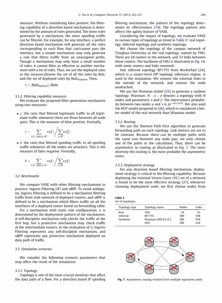
Fig. 7. Asymmetric routing resulted from multiple equivalent paths.
3.2. Benchmarks
We compare VASE with other filtering mechanisms inpractice: Ingress Filtering (IF) and uRPF. To avoid ambigu-ity, Ingress Filtering is defined to be a mechanism filteringtraffic from stub network of deployed routers, and uRPF isdefined to be a mechanism which filters traffic on all theinterfaces of a deployed router based on forwarding table.
For a mechanism with static rule configuration, r isdetermined by the deployment pattern of the mechanism.A self-discipline mechanism only checks the traffic at thefirst hop, but a protective mechanism may check trafficat the intermediate routers. In the evaluation of r, IngressFiltering represents any self-discipline mechanism, anduRPF represents any protective mechanism deployed ondata path of traffic.
3.3. Simulation scenarios
We consider the following scenario parameters thatmay affect the result of the simulation:
3.3.1. TopologyTopology is one of the most crucial elements that affect
the data path of a flow. For a direction based IP spoofing
filtering mechanism, the pattern of the topology deter-mines its effectiveness [14]. The topology pattern alsoaffects the agility feature of VASE.
Considering the impact of topology, we evaluate VASEin various types of topology as listed in Table 2: real topol-ogy, inferred topology and synthetic topology.
We choose the topology of the campus network ofTsinghua University as the real topology, named by THU.There are 24 routers in the network, and 33 links betweenthese routers. The backbone of THU is illustrated in Fig. 14,with some routers and links removed.
One inferred topology RF1755 from Rocketfuel [24],which is a router-level ISP topology inference engine, isused in the simulation. We remove the external links tothe outside of the network, and remove the nodeunattached.
We use the Waxman model [25] to generate a randomtopology. Waxman- N � a � b denotes a topology with Nnodes and parameters a and b. The interconnect probabil-ity between two nodes u and v is be�d(u,v)/aL. We also usedthe HOT model proposed in [26], which is considered a bet-ter model of the real network than Waxman model.
3.3.2. RoutingWe use the Shortest Path First algorithm to generate
forwarding path on each topology. Link metrics are set tobe constant. Because there can be multiple paths withthe same cost between any node pair, we only chooseone of the paths in the calculation. Thus, there can beasymmetric in routing as illustrated in Fig. 7. The morediversity the routing is, the more probable the asymmetricexists.
3.3.3. Deployment strategyFor any direction based filtering mechanism, deploy-
ment strategy is critical to the filtering capability. Becausedeploying the minimal Vertex Cover (VC) set of a networkis found to be the most effective strategy [27], wheneverchoosing deployment node, we first choose nodes from
Fig. 8. r in THU, RF1755, Waxman-200-0.2-0.2 and HOT with deployment ratio of 50%.
250 G. Yao et al. / Computer Networks 57 (2013) 243–257
the minimal VC set. After that, the other nodes are chosenrandomly. Evaluating the mechanisms using VC set repre-sents the best performance of mechanisms. Mechanismsare deployed on the same selected nodes.
3.3.4. The observer coverageIn the case that VASE generates filtering rules based on
flow path calculation, the spoofing filtering ability of VASEis affected by the coverage of router whose MIBs arecollected. We consider two extreme situations: (1) MIBsare only collected from the nodes to deploy; (2) MIBs arecollected from all the nodes in the network. The formeris denoted by VE-L, and the latter is denoted by VE-U.
3.3.5. Traffic patternIn the simulation, legitimate flows are launched be-
tween each node pair constantly. The relative volume offlow is determined by the relative flow space. For example,a (/23, /23) flow has four times volume of a (/24, /24) flow.
The pattern of attacking traffic is specified in eachscenario.
3.4. Evaluation results
3.4.1. Data plane overheadFig. 8. shows the increase of r with the increase of
attacker ratio, with deployment ratio of 50%. In the simula-tion, half of the nodes are chosen to perform filtering. Witheach attacker ratio, the corresponding proportion of nodesis chosen to be attacker and launch spoofing traffic withrandom source to a random chosen victim.
Note that r is the measure of additional process cost onnon-spoofing traffic. It can be found that VASE can avoidpacket filtering if there is no spoofing at all (attackerratio = 0). Even when there is spoofing in the network,VASE only configures the necessary filtering rules; thus,the process cost is still lower than Ingress Filtering anduRPF. Due to the perimeter, VASE checks a flow once atthe most. In case of 50% deployment ratio, the upper boundof r (VASE) is 0.5. This cost is equal to (Ingress Filtering). Aflow can be checked by uRPF for multiple times on thepath. Thus, r (uRPF) can be more than 1.
VASE has sampling cost. The sampling margin is alsoplotted in Fig. 8. Generally, the sampling rate is quite low
Fig. 9. s of THU, RF1755, Waxman-200-0.2-0.2 and HOT.
Fig. 10. The configured rule number to attacking flow count ratio.
G. Yao et al. / Computer Networks 57 (2013) 243–257 251
and the average process cost on each flow is only slightlyincreased. The total cost of the data plane is still far belowthe cost of the other mechanisms.
Through a comparison of VASE in different topologies,the impact of topology on VASE can be got. Apparently,power-law goes against agility. For example, in RF1755
0.0 0.1 0.2 0.3 0.4 0.5 0.6 0.7 0.8 0.9 1.00.00
0.02
0.04
0.06
0.08
0.10
THU(γ)
γ
Deployment Ratio
IF VE-L uRPF VE-U
0.0 0.1 0.2 0.3 0.4 0.5 0.6 0.7 0.8 0.9 1.00.0
0.1
0.2
0.3
0.4
0.5
RF1755(γ)
γ
Deployment Ratio
IF VE-L uRPF VE-U
0.0 0.1 0.2 0.3 0.4 0.5 0.6 0.7 0.8 0.9 1.00.0
0.1
0.2
0.3 IF VE-L uRPF VE-U
Waxman-200-0.2-0.2(γ)
γ
Deployment Ratio
0.0 0.1 0.2 0.3 0.4 0.5 0.6 0.7 0.8 0.9 1.00.00
0.01
0.02
0.03
0.04
0.05
IF VE-L uRPF VE-U
HOT(γ)
γ
Deployment Ratio
Fig. 11. c of THU, RF1755, Waxman-200-0.2-0.2 and HOT.
252 G. Yao et al. / Computer Networks 57 (2013) 243–257
which follows power-law, r (VASE) approaches (IngressFiltering) fast; in the random topology Waxman-200-0.2-0.2, the increase of r (VASE) is much slower. The reasonis explicit: a filter on a node will introduce cost on flowspassing by; a node of high rank can play as the intermedi-ary of a large number of paths in a network followingpower-law.
Fig. 9. shows the increase of s to the number of forgedaddresses of attackers. The result is got through calculatingthe ratio of configured filters in scenarios that an attackeruses brute force search generated source and randomlygenerated source. In the simulation, 65,535 prefixes aredistributed randomly to nodes in the network. In eachsearch step, the selected attacker chooses a forged addressto launch traffic to a random victim.
The result shows a static mechanism configures all therules all the time, but the configured rule ratio of VASE isproportional to the spoofing space of an attacker. Thismeans VASE can avoid occupying unnecessary resourceto filter out spoofing flows. Only the rules currently needare configured in VASE. Also, we find a random spoofingstrategy is not as effective as brute force search with the
increase of attack times. The topology has impact on theincrease of s under random spoofing strategy. For example,in HOT, the increase of s is quite slow. It is due to HOT is atree-like topology whose FlowTable can be well aggre-gated. Thus, a small number of rules can cover most ofthe spoofing space.
Fig. 10. shows the ratio of configured rules to the num-ber of attacking flows under brute force strategy. The ratiois obviously less than 1. This result shows the MaximumRectangle algorithm is effective to find the suitable ruleto cut spoofing traffic. With the Maximum Rectanglealgorithm, there is no need to configure a rule for eachspoofing flow. A spoofing flow can be covered by a de-ployed rule. This result implies an attacker must generatemore spoofing flows than configured rules by VASE. Also,the topology has impact on the ratio because it determineshow well the FlowTable can be aggregated.
3.4.2. Filtering capability3.4.2.1. False positive. Fig. 11. shows the false positive ofmechanisms in each topology. Unlike other mechanisms,uRPF is found of more or less false positive in each
Fig. 13. h of RF1755 with the increase of observer coverage.
G. Yao et al. / Computer Networks 57 (2013) 243–257 253
topology. This result implies uRPF is not a favorable protec-tive mechanism for current networks. In fact, based on thestatistic from MIT Spoofer project [9], most of the spoofingtraffic is filtered by the first router on the path. This impliesin realty, uRPF is used as a self-discipline mechanism, butnot a protective mechanism, because such deploymentcannot protect the network from spoofing launched byother networks. If uRPF is performed on a port not directly
attached by stub networks, it may discard legitimate trafficdue to asymmetric routing.
3.4.2.2. False negative. Fig. 12. shows the filtered spoofingtraffic ratio in each topology. VASE-U and uRPF are foundto be of approximate filtering capability. However, consid-ering the false positive of uRPF, VASE-U is more preferable.VASE-L has some advantage than Ingress Filtering in alltopologies. In RF1755, VASE-L has an obvious advantageagainst Ingress Filtering, resulted from the typical power-law structure of RF1755. Considering the power-lawfeature is becoming more and more notable in current net-works, even only cooperating a small fraction of nodes, theincreased filtering capability can be obvious.
To illustrate the effect of route information collectioncoverage to filtering capability, the filtering capability in-crease against the observer (the router to collect routeinformation) coverage ratio increase is plotted in Fig. 13.The result shows the benefit of the global view on VASEserver to the filtering capability. With better knowledgeof the network routing, the spoof filtering can achievebetter capability. Even when the number of nodes chosento perform filtering is small (1%), with a global view ofthe network, 50% spoofing traffic can be filtered out.
254 G. Yao et al. / Computer Networks 57 (2013) 243–257
4. Implementation and deployment
A prototype of the VASE has been implemented. Thesource code of this prototype can be fetched from http://netarchlab.tsinghua.edu.cn/�yaog/vase/src/.
We use sFlow [28] and NetFlow [29] on routers to sam-ple traffic. The export formats of different sampling mech-anisms are not identical. A tetrad (Router, Interface, Source,Destination) is used to represent the sampling result. VASEserver collects sampled packets and extracts the tetradsfrom the packets. The tetrads are inserted into a bufferwhich is used to handle burst of samples. The set structureis used to keep each tetrad unique to avoid checking onduplicate tetrads.
VASE server collects routing table MIB and interfacetable MIB on routers through the SNMP protocol, and gen-erates filtering rules to validate the samples. Because nostandard ACL MIB exists, to configure the Filtering Tableon each VASE node automatically, we choose to downloadthe rules using script through SSH. Thus, because the userinterface syntaxes of different vendors are different, thescript is generated on predefined template.
The implementation has been deployed in IPv6 campusnetwork of Tsinghua University, as illustrated in Fig. 14.Two perimeters are formed after the deployment. The rou-ters outside the VASE are not under the control of networkoperation group, and the forwarding choices of the routersare unpredictable; thus uRPF is unsuitable to be deployeddue to the potential false positive. Because NetFlow has
Fig. 14. The deployment of VASE in the IPv6 c
been enabled on the VASE interface already for manage-ment purposes, the deployment of the VASE brings noadditional overhead on the data plane. In spite of the trivialdeployment cost, if all the hosts in the campus networkattend in attacks against nodes in the network or out ofthe network, 89% spoofing flows can be filtered in averageaccording to the simulation using real routing table.Indeed, VASE has been deployed in the IPv6 campus net-work of 100 universities in China.
We got some performance data from the implementa-tion and deployment in Tsinghua University. The averagesample collection rate on VASE server is around 1200pps. Each sample check procedure can process around300 packets each second (note that there are generallymore than one flows in each NetFlow message); thus werun 8 procedures in parallel to handle a possible burst.The information collection and filtering rule generationcost 2.3 s in average, and the highest observed value is5.1 s till the submission. The average re-active time,including the sample check, spoofing confirmation andfilter configuration, is 2.8 s in the experiments. This valueshows VASE can react fast enough.
Till the submission of this paper, the deployed VASEmechanism has worked for 10 months. Though currentlythe spoofing DoS attacks in IPv6 world are rare (on theother hand, we have deployed SAVI solutions [30] on mostof the switches), thousands of spoofing events caused bywrong configuration of a 6to4 tunnel are detected andverified in the period. In the captured events, a host played
G. Yao et al. / Computer Networks 57 (2013) 243–257 255
as an exit of an unauthorized 6to4 tunnel. A ratio of IPv6traffic between other campuses, which should not passthe campus network of Tsinghua University, was attractedby the tunnel. As a result, it appeared the host was sendingtraffic with forged sources. Besides the events caused bythe tunnel, only one filter was deployed on an edge routerfor hundreds of times to cut a spoofing flow with source setto an address inside the perimeter, which seemed to becaused by a host with wrongly configured IP address.Indeed, in most of the time, no filtering is performed atall. This result proves the deployment of VASE can signifi-cantly reduce the unnecessary cost of IP spoofing filteringin peace time.
5. Related work and background
5.1. IP spoofing prevention mechanisms
As a long recognized security threat, IP spoofing attackshave been prevented by Ingress Filtering and IPsec [31] fora number of years. With Ingress Filtering, if a packet is notwith the source address of the network connected to itsincoming interface, it is getting filtered. The filtering isusually performed by manually configured ACL or uRPFcheck. There have been numerous Best Current Practices(BCPs) (BCP38, BCP84) and IETF RFCs about Ingress Filter-ing. Ingress Filtering is also a well-supported function oncommodity routers. Standardization and universally sup-port make Ingress Filtering widely deployed. Ingress Filter-ing is generally enabled at edge devices. In most cases, itrelies on the uRPF feature to build the correct filteringtable. On core routers, because there is no explicit bindingbetween prefix and interface, only traffic with bogusprefixes is filtered to prevent spoofing.
IPsec is employed in many scenarios supplying the abil-ity of authenticating the origin of the packet. The majorproblem of IPsec is that global distribution of the key is stilla challenge. Besides, IPsec is vulnerable to DDoS attack be-cause the attacking traffic has aggregated at the victimhost, and the computation cost of authentication is gener-ally not low enough.
There also have been a number of research works,which can be classified into two categories.
1: End-to-end authentication. Such mechanisms vali-date the source address at the other end of commu-nication (at different granularity). [18] proposed amechanism which inserts AS tag into data packetand check the binding between address prefix andAS tag at the destination AS. This mechanismrequires the association of ASs and update of routingdevices. HCF [19] checks the validation of sourceprefix based on the binding between prefix andhop count value which is inferred from remainingTTL value. HCF is light-weighted, and of no deploy-ment requirement, but it has significant false nega-tive because the forged network and the attackercan have non-trivial probability to have the samehops away from the destination, and it can bebypassed by smart attackers who modify the initial
TTL value. Also, it can result in false positive whenthe hop count value is inconsistent, e.g., in case ofroute change.
2: Filtering-on-path. Such mechanisms filter packetson the path, generally before the packet aggregatedat victim network. [14] proposed a direction basedfiltering mechanism, which filters packets based onthe binding between prefix/flow and interface. How-ever, the article does not propose a universal mech-anism to build the filtering table. [17] proposed amechanism that checks cryptographic signaturehop-by-hop at AS granularity. It can filter spoofingtraffic before they aggregate, and the filtering canbe performed at AS granularity, which is better thangeneral filtering-on-path mechanisms. However, thecost is also heavy: it requires the cooperation of ISPs,update of routing device, the update of client andmodification of the packet. [15] proposed a new pro-tocol on routing devices, which announce the localroute selection choice and help others build themapping table from incoming prefix to the interface.[16] builds inter-domain filtering rules based on thevalley-free feature of inter-domain routing and theBGP announcement filtering rules.
5.2. Related functions on commodity routers
In order to avoid updating routers to adopt this mecha-nism, the following functions widely supported on routerscan be exploited:
1. XFlow: XFlow is used to represent sFlow [28] or NetFlow[29] or other mechanisms on the router with samplingfunction. Generally such mechanisms are commonlyconfigured to monitor traffic pattern.
2. ACL: Whenever needed, ACL rules on routers are config-ured to enforce filtering. ACL performed by the hard-ware can achieve line-speed; thus the capacity ofrouters will not be affected.
3. SNMP and MIBs: SNMP can be used to fetch the routingtable and interface MIB on routers. The MIB content isused to generate correct filtering rules. For manage-ment purposes, SNMP is usually enabled in networks.
6. Discussions, conclusions and future work
6.1. Discussions
6.1.1. Discussions on comparison with uRPFCompared with uRPF, which is the most common IP
spoofing filtering mechanism, VASE requires deploying anadditional server. It seems an additional overhead, butgenerally there has been a server deployed in the networkhelping the network management. For example, a servermay be used to collect MIBs from routers with SNMP.The server can be used as the VASE server. Besides, VASEcan reduce data plane cost if only there is no permanentspoofing in the network.
Though uRPF is universally used, it has its ownweaknesses. Considering the false positive caused byasymmetric routing, uRPF is generally enabled on the edge
256 G. Yao et al. / Computer Networks 57 (2013) 243–257
routers. On the core routers, uRPF is not enabled, but non-directional ACL is used instead [32]. Such a deployment isactually self-discipline: it can filter spoofing from localedge networks, and cannot protect the network fromspoofing traffic launched by other domains. However,VASE does not introduce false positive in case of asymmet-ric routing. Thus, VASE can enable IP spoofing filtering onthe core routers, and protect routers inside the VASEperimeter from spoofing originated outside. Such a featureis essential to protect core infrastructures. Important serv-ers in a network are generally protected by access controlrules which only allow access from specified IP addresses.The access control rules cannot prevent the servers fromspoofing DoS traffic with source set to the allowed IP ad-dresses. However, VASE can filter out such spoofing trafficand provide better protection.
Another weakness of uRPF is that it discards trafficsilently. It is difficult for the administrator to diagnosethe problem when legitimate traffic is discarded by uRPF,and it is difficult for the administrator to notice an attackand take further actions. VASE can identify each spoofingexplicitly. This is the reason why we can detect the addressmisuses in campus network of Tsinghua University.
6.1.2. Security considerations on VASEIt is necessary to ensure the safety of the VASE server
and the channels between VASE server and routers. Withthe VASE perimeter, a straightforward solution can begiven: place the VASE server inside the perimeter. In thisway, the VASE server can be protected from spoofing at-tacks. Through setting the VASE server to be accessibleonly from the management addresses of routers, the VASEserver can be prevented from attack from malicious nodes,even with spoofing source IP address. Through setting themanagement addresses of routers to be accessible only bythe IP address of VASE server, the channels between theVASE server and the routers can be protected. In the cam-pus network of Tsinghua University, we just configure theIP address of the VASE server to an address belongs to themanagement network which owns a specified prefix, andprevent the management network from access from otherprefixes.
Note that if there is more than one perimeter, the chan-nels between the VASE server and the routers inside thedifferent perimeters can be accessible from maliciousnodes through spoofing. However, the channels can stillbe protected by the authentication mechanisms of SNMPand SSH, which are commonly enabled in network man-agement practice. At least, the deployment of VASE doesnot introduce more risk than existing protocols.
6.2. Conclusions
In this article, we proposed the mechanism to build aVirtual Anti-Spoofing Edge that filters spoofing traffic withagility, i.e., with flexible cost and resource requirement.Sampling, passive filtering generation mechanism andadaptive filter configuration significantly reduce the costwhen no spoofing or little spoofing happens. VASE is com-pared with other mechanisms based on simulation, andobvious advantage is found. We have implemented a pro-
totype of VASE and deploy it in the running network toprove this mechanism.
The primary design goal of VASE is practicability. Thus,no modification on routers is made. However, because ofthis restraint, VASE is not a state-of-art solution, e.g., thesampling cost, the outer-sync problem with filter genera-tion, and the filter deployment complexity of configurationthrough script. In the future, we plan to implement a VASEthat can cooperate with OpenFlow [21], and better resolvethe existing problems.
6.3. Future work: OpenFlow based solution
OpenFlow protocol can benefit VASE in sampling, filter-ing generation and filter configuration:
6.3.1. SamplingThe sampling rate is designed to capture most of the
significant attack. However, small attacks may not befound by the mechanism. Ideally, performing samplingon each flow only once is the most effective samplingmechanism to detect spoofing. In this situation, no sam-pling is wasted, and all the spoofing flow can be sampled.In OpenFlow, a packet-in event will be sent to the control-ler on each packet not matching any entry. This functioncan be used to replace the sampling mechanism. Flowentry associated with the event can be set to avoid futurecollection on the same flow. In this way, each flow canbe sampled once and only once.
6.3.2. Filter generationThe OpenFlow controller can tightly track the state of
routers through collecting the asynchronous messagesfrom routers. Moreover, the controller can even take con-trol of the flow tables on routers. Thus, filtering rules canbe generated more consistent with instant routing statewith OpenFlow.
6.3.3. Filter configurationThe protocol of OpenFlow provides a uniform interface
for the controller to modify the flow table on routers. Thus,the differences in router UI syntax can be eliminated. Fil-ters can be easily configured on any router that supportsthe OpenFlow protocol.
We have implemented a similar mechanism based onOpenFlow/NOX for access networks [33], as a complementof SAVI [30]. However, the intra-domain network is differ-ent from the access network. The topology of the accessnetwork is simple, and a controller can be used to deter-mine all the data paths. However, an intra-domain net-work is more complex. It is of considerable cost to takecomplete control of all the data paths in an intra-domainnetwork, and generally it is not necessary. Thus, weproposed OpenRouter [34], which supports OpenFlow pro-tocol but routes are generated mostly based on routingprotocols. We are implementing a VASE with OpenRouter.
Acknowledgements
This work is supported by National Science Foundationof China under Grant 61073172, Program for the New
G. Yao et al. / Computer Networks 57 (2013) 243–257 257
Century Excellent Talents in University, Specialized Re-search Fund for the Doctoral Program of Higher Educationof China under Grant 20090002110026, and National BasicResearch Program (‘‘973’’ Program) of China under Grant2009CB320501. We are grateful to anonymous reviewersfor the comments that helped us improve the manuscript.
References
[1] S.M. Bellovin, Security problems in the TCP/IP protocol suite,SIGCOMM Computer Communication Review 19 (2) (1989) 32–48.
[2] CERT, TCP SYN Flooding and IP Spoofing Attacks, 1996. <http://www.cert.org/advisories/CA-1996-21.html>.
[3] CERT, Smurf IP Denial-of-Service Attacks, 1998. <http://www.cert.org/advisories/CA-1998-01.html>.
[4] R. Vaughn, G. Evron, DNS Amplification Attacks, 2006. <http://www.isotf.org/news/DNS-Amplification-Attacks.pdf>.
[5] ICANN, SSAC Advisory SAC008 DNS Distributed Denial of Service(DDoS) Attacks, 2006.
[6] D. Moore et al., Inferring Internet denial-of-service activity, ACMTransactions on Computer Systems 24 (2) (2006) 115–139.
[7] C. Labovitz, Bots, DDoS and Ground Truth, 2011. <http://www.nanog.org/meetings/nanog50/presentations/Tuesday/NANOG50.Talk58.groundtruth.pdf>.
[8] P. Ferguson, D. Senie, Network Ingress Filtering: Defeating Denial ofService Attacks which employ IP Source Address Spoofing(RFC2827),2000. http://tools.ietf.org/rfc/rfc2827.txt.
[9] R. Beverly et al., Understanding the efficacy of deployed internetsource address validation filtering. IMC’09: Proceedings of the 2009Acm Sigcomm Internet Measurement Conference, 2009, pp. 356–369.
[11] F. Baker, P. Savola, Ingress Filtering for Multihomed Networks(RFC3704), 2004. <http://www.ietf.org/rfc/rfc3704.txt>.
[12] D. Rajnovic, Black Hole Routers, 2002. <http://www.terena.org/activities/tf-csirt/meeting7/rajnovic-black-hole-routers.pdf>.
[13] D. Meyer, L. Zhang, K. Fall, Report from the IAB Workshop on Routingand Addressing, 2007. <http://tools.ietf.org/html/draft-iab-raws-report-01>.
[14] K. Park, H. Lee, On the effectiveness of route-based packet filteringfor distributed DoS attack prevention in power-law Internets,Computer Communication Review 31 (4) (2001) 15–26.
[15] J. Li et al., SAVE: source address validity enforcement protocol, in:Proceedings of the IEEE Infocom 2002: The Conference on ComputerCommunications, vols. 1–3, 2002, pp. 1557–1566.
[16] Z.H.Duan,X.Yuan,J.Chandrashekar,Constructinginter-domainpacketfilterstocontrolIPspoofingbasedonBGPupdates,in:ProceedingsoftheIEEE Infocom 2006: 25th IEEE International Conference on ComputerCommunications, vols. 1–7, 2006, pp. 510–521.
[17] X. Liu et al., Passport: secure and adoptable source authentication,in: Proceedings of the 5th USENIX Symposium on NetworkedSystems Design and Implementation 2008, USENIX Association:San Francisco, California, 2008, pp. 365–378.
[18] A. Bremler-Barr, H. Levy, Spoofing prevention method, in:Proceedings of the IEEE Infocom 2005: The Conference onComputer Communications, vols. 1–4, 2005, pp. 536–547.
[19] H.N. Wang, C. Jin, K.G. Shin, Defense against spoofed IP traffic usinghop-count filtering, IEEE–ACM Transactions on Networking 15 (1)(2007) 40–53.
[20] A. Greenberg et al., A clean slate 4D approach to network control andmanagement, Computer Communication Review 35 (5) (2005) 41–+.
[21] N. McKeown et al., OpenFlow: enabling innovation in campusnetworks, Computer Communication Review 38 (2) (2008) 69–74.
[22] M. Casado et al., Ethane: taking control of the enterprise, ComputerCommunication Review 37 (4) (2007) 1–12.
[23] K. Levenberg, A method for the solution of certain non-linearproblems in least squares, Quarterly of Applied Mathematics 2(1944) 164–168.
[24] N. Spring et al., Measuring ISP topologies with rocketfuel, IEEE–ACMTransactions on Networking 12 (1) (2004) 2–16.
[25] B.M. Waxman, Routing of multipoint connections, IEEE Journal onSelected Areas in Communications 6 (9) (1988) 1617–1622.
[26] L. Li et al., A first-principles approach to understanding the Internet’srouter-level topology, Computer Communication Review 34 (4)(2004) 3–14.
[27] B. Armbruster, J.C. Smith, K. Park, A packet filter placement problemwith application to defense against spoofed denial of service attacks,European Journal of Operational Research 176 (2) (2007) 1283–1292.
[28] P. Phaal, S. Panchen, N. McKee, InMon Corporation’s sFlow: AMethod for Monitoring Traffic in Switched and RoutedNetworks(RFC3176), 2001. <http://tools.ietf.org/rfc/rfc3176.txt>.
[29] CISCO, Introduction to Cisco IOS NetFlow – A Technical Overview,2007. <http://www.cisco.com/en/US/prod/collateral/iosswrel/ps6537/ps6555/ps6601/prod_white_paper0900aecd80406232.html>.
[30] J. Wu, J. Bi, M. Bagnulo, F. Baker, C. Vogt, Source Address ValidationImprovement Framework, 2011.
[31] S. Kent, R. Atkinson, IP Encapsulating Security Payload (ESP)(RFC2406), 1998.
[33] Y. Guang, B. Jun, X. Peiyao, Source address validation solution withOpenFlow/NOX architecture, in: 19th IEEE International Conferenceon Network Protocols (ICNP), 2011.
[34] F. Tao, B. Jun, H. Hongyu. OpenRouter: OpenFlow extension andimplementation based on a commercial router, in: 19th IEEEInternational Conference on Network Protocols (ICNP), 2011.
Guang Yao received the B.S. and Ph.D. degreein computer science from Tsinghua Univer-sity. Currently he is a Post-Doctoral fellow ofTsinghua University.
Jun Bi received the B.S., M.S., and Ph.D. degreein computer science from Tsinghua Univer-sity. Currently he is a full professor anddirector of Network Architecture & IPv6Research Division, Network Research Centerof Tsinghua University, Beijing, China.
Peiyao Xiao received the B.S. degree in com-puter science from Tsinghua University. Cur-rently she is working toward a Master’sDegree.