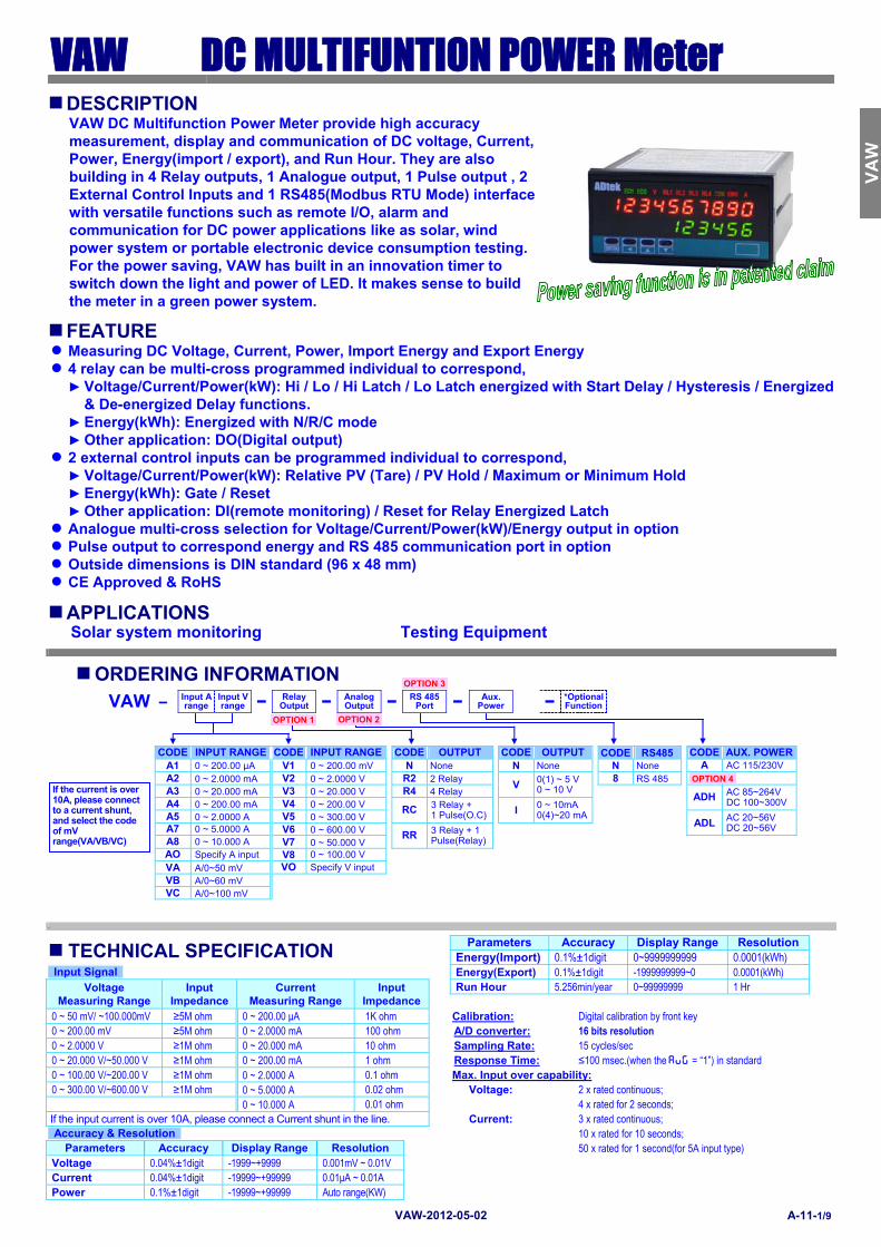
VAW-2012-05-02 A-11-1/9 VAW DC MULTIFUNTION POWER Meter DESCRIPTION VAW DC Multifunction Power Meter provide high accuracy measurement, display and communication of DC voltage, Current, Power, Energy(import / export), and Run Hour. They are also building in 4 Relay outputs, 1 Analogue output, 1 Pulse output , 2 External Control Inputs and 1 RS485(Modbus RTU Mode) interface with versatile functions such as remote I/O, alarm and communication for DC power applications like as solar, wind power system or portable electronic device consumption testing. For the power saving, VAW has built in an innovation timer to switch down the light and power of LED. It makes sense to build the meter in a green power system. FEATURE ● Measuring DC Voltage, Current, Power, Import Energy and Export Energy ● 4 relay can be multi-cross programmed individual to correspond, ► Voltage/Current/Power(kW): Hi / Lo / Hi Latch / Lo Latch energized with Start Delay / Hysteresis / Energized & De-energized Delay functions. ► Energy(kWh): Energized with N/R/C mode ► Other application: DO(Digital output) ● 2 external control inputs can be programmed individual to correspond, ► Voltage/Current/Power(kW): Relative PV (Tare) / PV Hold / Maximum or Minimum Hold ► Energy(kWh): Gate / Reset ► Other application: DI(remote monitoring) / Reset for Relay Energized Latch ● Analogue multi-cross selection for Voltage/Current/Power(kW)/Energy output in option ● Pulse output to correspond energy and RS 485 communication port in option ● Outside dimensions is DIN standard (96 x 48 mm) ● CE Approved & RoHS APPLICATIONS Solar system monitoring Testing Equipment ORDERING INFORMATION VAW – Input A range Input V range − Relay Output − Analog Output − RS 485 Port − Aux. Power − *Optional Function CODE INPUT RANGE CODE INPUT RANGE CODE OUTPUT CODE OUTPUT CODE RS485 CODE AUX. POWER A1 0 ~ 200.00 μA V1 0 ~ 200.00 mV N None N None N None A AC 115/230V A2 0 ~ 2.0000 mA V2 0 ~ 2.0000 V R2 2 Relay V 0(1) ~ 5 V 0 ~ 10 V 8 RS 485 A3 0 ~ 20.000 mA V3 0 ~ 20.000 V R4 4 Relay ADH AC 85~264V DC 100~300V A4 0 ~ 200.00 mA V4 0 ~ 200.00 V RC 3 Relay + 1 Pulse(O.C) I 0 ~ 10mA 0(4)~20 mA A5 0 ~ 2.0000 A V5 0 ~ 300.00 V ADL AC 20~56V DC 20~56V A7 0 ~ 5.0000 A V6 0 ~ 600.00 V RR 3 Relay + 1 Pulse(Relay) A8 0 ~ 10.000 A V7 0 ~ 50.000 V AO Specify A input V8 0 ~ 100.00 V VA A/0~50 mV VO Specify V input VB A/0~60 mV VC A/0~100 mV , TECHNICAL SPECIFICATION Parameters Accuracy Display Range Resolution Energy(Import) 0.1%±1digit 0~9999999999 0.0001(kWh) Input Signal Energy(Export) 0.1%±1digit -1999999999~0 0.0001(kWh) Voltage Measuring Range Input Impedance Current Measuring Range Input Impedance Run Hour 5.256min/year 0~99999999 1 Hr 0 ~ 50 mV/ ~100.000mV ≥5M ohm 0 ~ 200.00 μA 1K ohm Calibration: Digital calibration by front key 0 ~ 200.00 mV ≥5M ohm 0 ~ 2.0000 mA 100 ohm A/D converter: 16 bits resolution 0 ~ 2.0000 V ≥1M ohm 0 ~ 20.000 mA 10 ohm Sampling Rate: 15 cycles/sec 0 ~ 20.000 V/~50.000 V ≥1M ohm 0 ~ 200.00 mA 1 ohm Response Time: ≤100 msec.(when the avg = “1”) in standard 0 ~ 100.00 V/~200.00 V ≥1M ohm 0 ~ 2.0000 A 0.1 ohm Max. Input over capability: 0 ~ 300.00 V/~600.00 V ≥1M ohm 0 ~ 5.0000 A 0.02 ohm Voltage: 2 x rated continuous; 0 ~ 10.000 A 0.01 ohm 4 x rated for 2 seconds; If the input current is over 10A, please connect a Current shunt in the line. Current: 3 x rated continuous; Accuracy & Resolution 10 x rated for 10 seconds; Parameters Accuracy Display Range Resolution 50 x rated for 1 second(for 5A input type) Voltage 0.04%±1digit -1999~+9999 0.001mV ~ 0.01V Current 0.04%±1digit -19999~+99999 0.01μA ~ 0.01A Power 0.1%±1digit -19999~+99999 Auto range(KW) CSM-321S VAW CSM-321S CSM- CSM- CSM-321S CSM-321S CSM- CSM- CSM-321S CSM- CSM-321S OPTION 1 OPTION 3 OPTION 2 OPTION 4 If the current is over 10A, please connect to a current shunt, and select the code of mV range(VA/VB/VC)
Transcript
VAW-2012-05-02 A-11-1/9
VAW DC MULTIFUNTION POWER Meter
DESCRIPTION VAW DC Multifunction Power Meter provide high accuracy measurement, display and communication of DC voltage, Current, Power, Energy(import / export), and Run Hour. They are also building in 4 Relay outputs, 1 Analogue output, 1 Pulse output , 2 External Control Inputs and 1 RS485(Modbus RTU Mode) interface with versatile functions such as remote I/O, alarm and communication for DC power applications like as solar, wind power system or portable electronic device consumption testing.For the power saving, VAW has built in an innovation timer to switch down the light and power of LED. It makes sense to build the meter in a green power system.
FEATURE Measuring DC Voltage, Current, Power, Import Energy and Export Energy 4 relay can be multi-cross programmed individual to correspond,
Voltage/Current/Power(kW): Hi / Lo / Hi Latch / Lo Latch energized with Start Delay / Hysteresis / Energized & De-energized Delay functions.
Energy(kWh): Energized with N/R/C mode Other application: DO(Digital output)
2 external control inputs can be programmed individual to correspond, Voltage/Current/Power(kW): Relative PV (Tare) / PV Hold / Maximum or Minimum Hold Energy(kWh): Gate / Reset Other application: DI(remote monitoring) / Reset for Relay Energized Latch
Analogue multi-cross selection for Voltage/Current/Power(kW)/Energy output in option Pulse output to correspond energy and RS 485 communication port in option Outside dimensions is DIN standard (96 x 48 mm) CE Approved & RoHS
APPLICATIONS Solar system monitoring Testing Equipment
ORDERING INFORMATION
VAW – Input A range
Input V range − Relay
Output − Analog Output − RS 485
Port − Aux. Power − *Optional
Function
CODE INPUT RANGE CODE INPUT RANGE CODE OUTPUT CODE OUTPUT CODE RS485 CODE AUX. POWER
A1 0 ~ 200.00 μA V1 0 ~ 200.00 mV N None N None N None A AC 115/230V A2 0 ~ 2.0000 mA V2 0 ~ 2.0000 V R2 2 Relay
V 0(1) ~ 5 V 0 ~ 10 V
8 RS 485 A3 0 ~ 20.000 mA V3 0 ~ 20.000 V R4 4 Relay
ADH AC 85~264V DC 100~300V A4 0 ~ 200.00 mA V4 0 ~ 200.00 V RC 3 Relay +
1 Pulse(O.C) I 0 ~ 10mA 0(4)~20 mA
A5 0 ~ 2.0000 A V5 0 ~ 300.00 V
ADL AC 20~56V
DC 20~56V A7 0 ~ 5.0000 A V6 0 ~ 600.00 V RR 3 Relay + 1 Pulse(Relay)
A8 0 ~ 10.000 A V7 0 ~ 50.000 V AO Specify A input V8 0 ~ 100.00 V VA A/0~50 mV VO Specify V input VB A/0~60 mV VC A/0~100 mV
,
TECHNICAL SPECIFICATION Parameters Accuracy Display Range Resolution
Energy(Import) 0.1%±1digit 0~9999999999 0.0001(kWh) Input Signal Energy(Export) 0.1%±1digit -1999999999~0 0.0001(kWh)
Voltage Measuring Range
Input Impedance
Current Measuring Range
Input Impedance
Run Hour 5.256min/year 0~99999999 1 Hr
0 ~ 50 mV/ ~100.000mV ≥5M ohm 0 ~ 200.00 μA 1K ohm Calibration: Digital calibration by front key 0 ~ 200.00 mV ≥5M ohm 0 ~ 2.0000 mA 100 ohm A/D converter: 16 bits resolution 0 ~ 2.0000 V ≥1M ohm 0 ~ 20.000 mA 10 ohm Sampling Rate: 15 cycles/sec 0 ~ 20.000 V/~50.000 V ≥1M ohm 0 ~ 200.00 mA 1 ohm Response Time: ≤100 msec.(when the avg = “1”) in standard 0 ~ 100.00 V/~200.00 V ≥1M ohm 0 ~ 2.0000 A 0.1 ohm Max. Input over capability: 0 ~ 300.00 V/~600.00 V ≥1M ohm 0 ~ 5.0000 A 0.02 ohm Voltage: 2 x rated continuous; 0 ~ 10.000 A 0.01 ohm 4 x rated for 2 seconds; If the input current is over 10A, please connect a Current shunt in the line. Current: 3 x rated continuous; Accuracy & Resolution 10 x rated for 10 seconds;
Parameters Accuracy Display Range Resolution 50 x rated for 1 second(for 5A input type) Voltage 0.04%±1digit -1999~+9999 0.001mV ~ 0.01V Current 0.04%±1digit -19999~+99999 0.01μA ~ 0.01A Power 0.1%±1digit -19999~+99999 Auto range(KW)
CS
M-3
21S
V
AW
C
SM
-321
S
CS
M-
CS
M-
CS
M-3
21S
C
SM
-321
S
CS
M-
CS
M-
CS
M-3
21S
C
SM
-C
SM
-321
S
OPTION 1
OPTION 3
OPTION 2
OPTION 4If the current is over 10A, please connect to a current shunt, and select the code of mV range(VA/VB/VC)
VAW-2012-05-02 A-11-2/9
Display & Functions External Control Inputs(ECI) Numeric LED: Dual display; 0.28”(7.1mm) high-brightness Input Mode: 2 ECI points, Contact or open collect input, Level trigger Up-row for 10 digits red LED Functions: There are flexible functions can be programmed for down-row for 6 digits green LED Corresponds to Current / Voltage / Power(kW) Pages scroll: 5 pages switchable to show all parameters
Page 1: Voltage(4 digits), Current(5 digits) and Power Page 2: Voltage(5 digits), Current(4 digits) and Power Page 3: Import Energy and Power Page 4: Export Energy and Power Page 5: Run Hour and Power
Relative PV / PV Hold / Reset Max or Mini. Hold Corresponds to Energy(+kWh / -kWh)
Gate / Reset DI function monitoring by RS485 command of master. Debouncing time: Settable range 5 ~255 x (8mseconds)
I/O Status Indication: 10 square LED Analogue output(option) Relay energized & Pulse(RL4 specify) indication:
4 square red LED Multi-cross function: User can program the output to correspond Current, Voltage,
Power(kW) and Energy(+kWh / -kWh)
E.C.I. function indication: 2 square green LED Accuracy: ≤ 0.1% of F.S.; 16 bits DA converter RS 485 communication: 1 square orange LED Ripple: ≤ 0.1% of F.S.
V and A identify & unit: 2 square red LED Response time: ≤100 msec. (10~90% of input)
kWh identify & unit: 1 square red LED Isolation: AC 2.0 KV between input and output Scaling function: There are two scaling functions to program individual for two
isolation input. Output range: Specify either Voltage or Current output in ordering
Power(kW): Auto-range display from -19999~±0.0001~99999(kW) according to the multiply between voltage and current. And the decimal point will be decided by the higher resolution between voltage and current.
Energy(-kWh): -1999999999~0
[ aOls]output range Low: Settable range:
Voltage: -1999~+9999 Current: -19999~+99999 Over range indication: [ ovfl]overflow: when input is over 120% of input range Hi Power(kW): -19999~99999; Under range indication: [-ovfl]-overflow: when input is under -120% of input range Lo Energy(+kWh): 0~9999999999 Max / Mini recording: Maximum and Minimum value storage for voltage, Current and
Power during power on. Energy(-kWh): -1999999999~0
[aOlmt]output High Limit: 0.00~110.00% of output High Low cut: [_.lOct]Low Cut: Settable range: -19999~29999 Digital fine adjust: [aOzro]: Settable range: -38011~+27524 Digital fine adjust: [_.pVzo] _.Pv.Zo: Settable range: -19999~+99999 [aOspn]: Settable range: -38011~+27524 [_.pVsn] _.Pv.Sn: Settable range: -19999~+99999 Pulse output(option) Reading Stable Function Output mode: Open collect: 30V/60mA or Relay: DC24V/1A (The output
frequency has to under 50Hz); Please specify in ordering Average: [ avg]: Settable range: 1~99 times Moving average: [ Mavg]: Settable range: 1(None)/~10 times Output range: Maximum frequency: 1000Hz; duty cycle 50% Digital filter: [Dfilt]:Settable range: 0(None)/1~99 times Pulse divider: 1 Pulse/1~9999 Count programmable. Control Functions(option) RS 485 Communication(optional) Set-points: Four set-points Protocol: Modbus RTU mode Range: Voltage: -1999~+9999 ﹔Current: -19999~+99999 Baud Rate: 1200/2400/4800/9600/19200/38400 programmable Power(kW): -19999~+99999 Data Bits: 8 bits Energy(+kWh): 0~9999999999 Parity: Even, odd or none (with 1 or 2 stop bit) programmable Energy(-kWh): -1999999999~0 Address: 1 ~ 255 programmable Control relay: Four relays Distance: 1200M Relay 2 & Relay 3: Dual FORM-C, 1A/230Vac, 3A/115V Terminate resistor: 150Ω at last unit. Relay 1 & Relay 4: Dual FORM-A, 1A/230Vac, 3A/115V Relay energized mode: Multi-cross programming for all parameters and energized
mode. Electrical Safety
Dielectric strength: AC 2.0 KV for 1 min, Between Power / Input / Output / Case Corresponds to Current / Voltage / Power(kW) Insulation resistance: ≥100M ohm at 500Vdc, Between Power / Input / Output
Functions: Energized levels compare with set-points: Isolation: Between Power / Input / Relay / Analogue / RS485 / E.C.I. Hi / Lo / Hi.HLd / Lo.HLd programmable EMC: EN 55011:2002; EN 61326:2003
Power consumption: 5.0VA maximum 3.0VA maximum in power saving mode
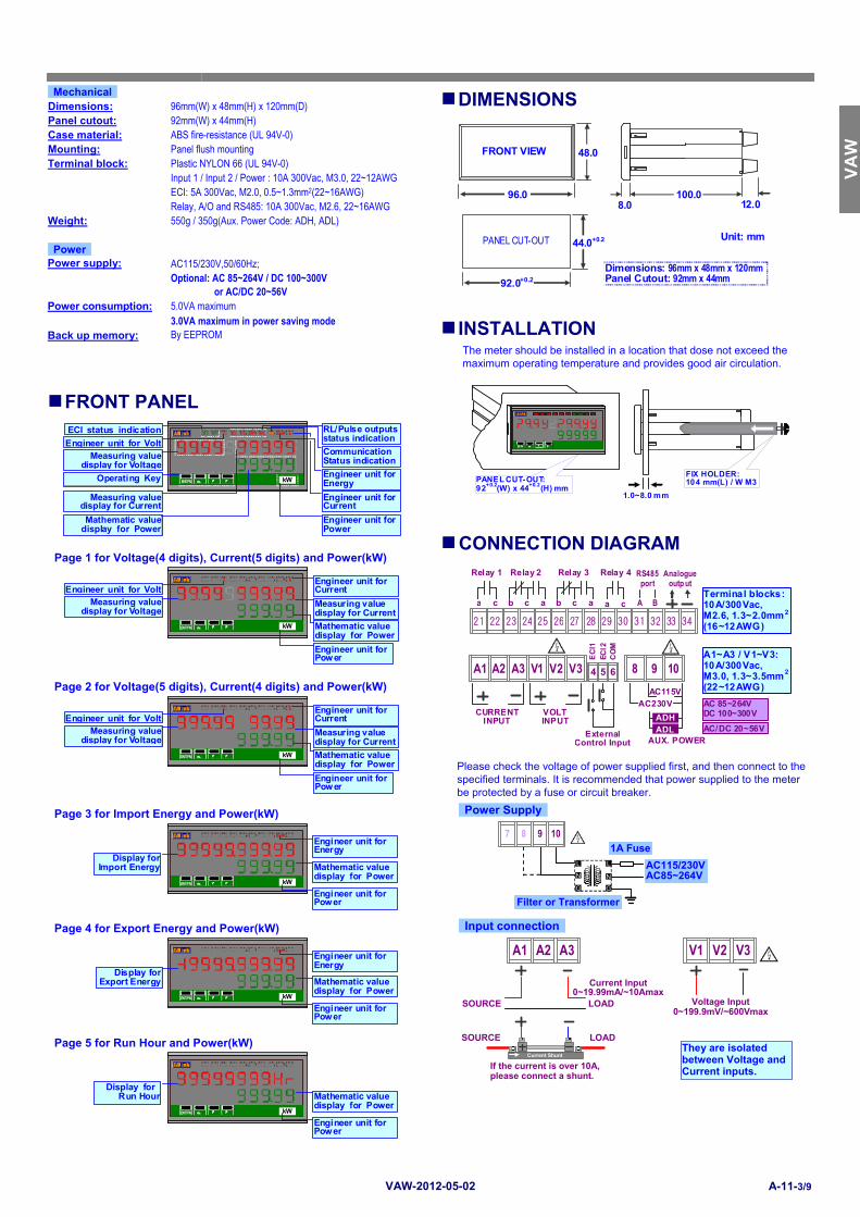
INSTALLATION Back up memory: By EEPROM
The meter should be installed in a location that dose not exceed the maximum operating temperature and provides good air circulation.
1.0~8.0 mm
FIX HOLDER:104 mm(L) / W M3PANEL CUT-OUT:
92+0.2(W) x 44+0.2(H) mm
CO V RY RY E CI kRY R Y EC A
ENT /FN ? ? ?
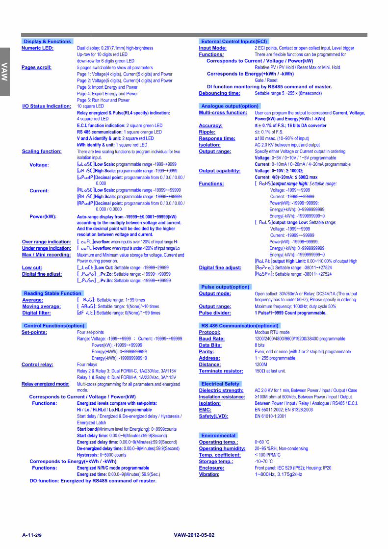
FRONT PANEL
ENT/FN ? ? ?
EC I1 ECI2 V RY1 COM kwh R Y2 RY3 RY4 A
kW
Measuring value display for Voltage
ECI status indication
Operating Key
RL/Pulse outputsstatus indicationEngineer unit for VoltCommunicationStatus indication
Engineer unit for Energy
Engineer unit for Current
Engineer unit for Power
Measuring value display for Current
Mathematic value display for Power
CONNECTION DIAGRAM Page 1 for Voltage(4 digits), Current(5 digits) and Power(kW)
ENT/FN ? ? ?
EC I1 ECI2 V RY1 COM kwh R Y2 RY3 RY4 A
kW
Measuring value display for Voltage
Engineer unit for Current
Engineer unit for Power
Measuring valuedisplay for Current
Mathematic valuedisplay for Power
Engineer unit for Volt
A3 A1 A2
21 22 24 2523 27 2826 29 30 31 3332 34
Relay 3
b c a
Relay 2
b c a
Relay 1
a c
Relay 4
a c
Analogueoutp ut
A B
RS485 port
AC 85~264VDC 100~300V
AC/DC 20~56VAUX. POWER
Terminal blocks:10A/300Vac, M2.6, 1.3~2.0mm2
(16~12AWG)
A1~A3 / V1~V3:10A/300Vac, M3.0, 1.3~3.5mm2
(22~12AWG)
V3 V1 V2 4 5 6
EC
I1
EC
I2
CO
M
AC230V AC115V
ADL
ADH
10 9 8
External Control Input
VOLT INPUT
CURRENT INPUT
Page 2 for Voltage(5 digits), Current(4 digits) and Power(kW)
ENT/FN ? ? ?
EC I1 ECI2 V RY1 COM kwh R Y2 RY3 RY4 A
kW
Measuring value display for Voltage
Engineer unit for Current
Engineer unit for Power
Measuring valuedisplay for Current
Mathematic valuedisplay for Power
Engineer unit for Volt
Please check the voltage of power supplied first, and then connect to the specified terminals. It is recommended that power supplied to the meter be protected by a fuse or circuit breaker.
Page 3 for Import Energy and Power(kW)
ENT/FN ? ? ?
EC I1 ECI2 V RY1 COM kwh R Y2 RY3 RY4 A
kW
Display for Import Energy
Engineer unit for Energy
Engineer unit for Power
Mathematic valuedisplay for Power
Power Supply
AC115/230V AC85~264V
Filter or Transformer
L
N
G
L
N
G
1A Fuse
7 9 10 8
Page 4 for Export Energy and Power(kW)
ENT/FN ? ? ?
EC I1 ECI2 V RY1 COM kwh R Y2 RY3 RY4 A
kW
Display for Export Energy
Engineer unit for Energy
Engineer unit for Power
Mathematic valuedisplay for Power
Input connection They are isolated
between Voltage and Current inputs.
V3 V1 V2
Voltage Input0~199.9mV/~600Vmax
A3 A1 A2
Current Input 0~19.99mA/~10Amax
LOAD SOURCE
Current Shunt
SOURCE LOAD
If the current is over 10A, please connect a shunt.
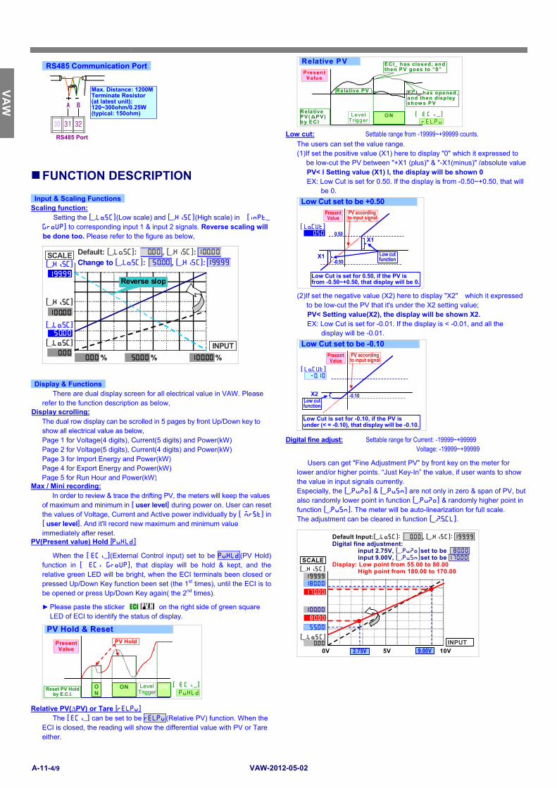
Low cut: Settable range from -19999~+99999 counts. The users can set the value range.
(1)If set the positive value (X1) here to display "0" which it expressed to be low-cut the PV between "+X1 (plus)" & "-X1(minus)" /absolute valuePV< l Setting value (X1) l, the display will be shown 0 EX: Low Cut is set for 0.50. If the display is from -0.50~+0.50, that will
be 0.
Low Cut set to be +0.50
Low Cut is set for 0.50, if the PV is from -0.50~+0.50, that display will be 0.
PV according to input signal
Present Value
Low cut function
0.50
-0.50
)50 [ lOcut]
X1
X1
(2)If set the negative value (X2) here to display "X2" which it expressed
to be low-cut the PV that it's under the X2 setting value; PV< Setting value(X2), the display will be shown X2. EX: Low Cut is set for -0.01. If the display is < -0.01, and all the
display will be -0.01.
Low Cut set to be -0.10
-0.10 Low cut function
Low Cut is set for -0.10, if the PV is under (< = -0.10), that display will be -0.10.
Present Value
PV according to input signal
-)10[ lOcut]
X2
FUNCTION DESCRIPTION
Input & Scaling Functions
Scaling function:
Setting the [_.lOsc](Low scale) and [_.hIsc](High scale) in [inpT_ group] to corresponding input 1 & input 2 signals. Reverse scaling will be done too. Please refer to the figure as below,
There are dual display screen for all electrical value in VAW. Please refer to the function description as below,
Display scrolling:
The dual row display can be scrolled in 5 pages by front Up/Down key to show all electrical value as below, Page 1 for Voltage(4 digits), Current(5 digits) and Power(kW) Page 2 for Voltage(5 digits), Current(4 digits) and Power(kW) Page 3 for Import Energy and Power(kW) Page 4 for Export Energy and Power(kW) Page 5 for Run Hour and Power(kW)
Digital fine adjust: Settable range for Current: -19999~+99999 Voltage: -19999~+99999
Users can get "Fine Adjustment PV" by front key on the meter for lower and/or higher points. “Just Key-In” the value, if user wants to show the value in input signals currently. Especially, the [_.pVzo] & [_.pVsn] are not only in zero & span of PV, but also randomly lower point in function [_.pVzo] & randomly higher point in function [_.pVsn]. The meter will be auto-linearization for full scale. The adjustment can be cleared in function [_.ZScl].
Max / Mini recording:
In order to review & trace the drifting PV, the meters will keep the values of maximum and minimum in [ user level] during power on. User can reset the values of Voltage, Current and Active power individually by [ Mrst] in[ user level]. And it'll record new maximum and minimum value immediately after reset.
Default Input:[_.lOsc]: )00 , [_.hIsc]: 19(99Digital fine adjustment:
input 2.75V, [_.pVzo]set to be 8)00 input 9.00V, [_.pVsn]set to be 17)00 Display: Low point from 55.00 to 80.00 High point from 180.00 to 170.00
SCALE
INPUT _0V 10V 5V2.75V 9.00V
19(99[_.hIsc]
[_.lOsc] )00
10)00
18)00
5%00
8)00
17)00
PV(Present value) Hold [pVhld]
When the [ ecI_](External Control input) set to be pVhld(PV Hold) function in [ eci group], that display will be hold & kept, and the relative green LED will be bright, when the ECI terminals been closed or pressed Up/Down Key function been set (the 1st times), until the ECI is to be opened or press Up/Down Key again( the 2nd times).
Please paste the sticker PV.H ECI on the right side of green square LED of ECI to identify the status of display.
PV Hold & Reset
Present Value
Reset PV Hold by E.C.I.
ON
Level Trigger
ON ON
PV Hold
pVhld[ ecI_ ]
Relative PV(∆PV) or Tare [reLpv] The [ ecI_] can be set to be reLpv(Relative PV) function. When the
ECI is closed, the reading will show the differential value with PV or Tare either.
CS
M-3
21S
VA
W
CS
M-3
21S
C
SM
-C
SM
-C
SM
-321
S
CS
M-3
21S
C
SM
-C
SM
-C
SM
-321
S
CS
M-
CS
M-3
21S
VAW-2012-05-02 A-11-5/9
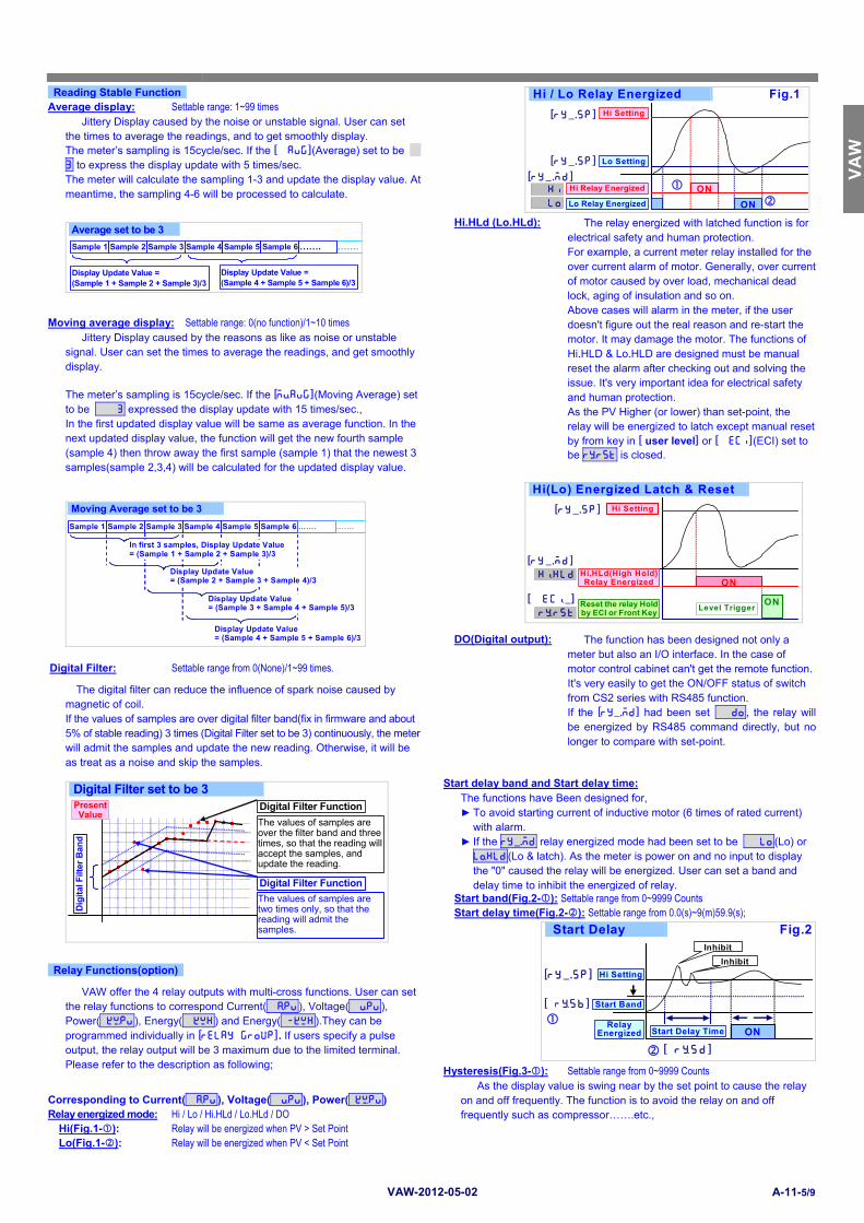
Reading Stable Function Hi / Lo Relay Energized Fig.1
Hi Setting
Hi Relay Energized ON
Lo Setting
Lo Relay Energized ON
hilo
[ry_.sp]
[ry_.sp] [ry_.md]
Average display: Settable range: 1~99 times Jittery Display caused by the noise or unstable signal. User can set
the times to average the readings, and to get smoothly display.
The meter’s sampling is 15cycle/sec. If the [ avg](Average) set to be 3 to express the display update with 5 times/sec. The meter will calculate the sampling 1-3 and update the display value. At meantime, the sampling 4-6 will be processed to calculate.
Hi.HLd (Lo.HLd): The relay energized with latched function is for
electrical safety and human protection. For example, a current meter relay installed for the over current alarm of motor. Generally, over current of motor caused by over load, mechanical dead lock, aging of insulation and so on. Above cases will alarm in the meter, if the user doesn't figure out the real reason and re-start the motor. It may damage the motor. The functions of Hi.HLD & Lo.HLD are designed must be manual reset the alarm after checking out and solving the issue. It's very important idea for electrical safety and human protection. As the PV Higher (or lower) than set-point, the relay will be energized to latch except manual reset by from key in [ user level] or [ eci](ECI) set to be rYrst is closed.
Moving average display: Settable range: 0(no function)/1~10 times Jittery Display caused by the reasons as like as noise or unstable
signal. User can set the times to average the readings, and get smoothly display.
The meter’s sampling is 15cycle/sec. If the [mVavg](Moving Average) set to be 3 expressed the display update with 15 times/sec., In the first updated display value will be same as average function. In the next updated display value, the function will get the new fourth sample (sample 4) then throw away the first sample (sample 1) that the newest 3 samples(sample 2,3,4) will be calculated for the updated display value.
DO(Digital output): The function has been designed not only a meter but also an I/O interface. In the case of motor control cabinet can't get the remote function. It's very easily to get the ON/OFF status of switch from CS2 series with RS485 function. If the [ry_.md] had been set do, the relay will be energized by RS485 command directly, but no longer to compare with set-point.
Digital Filter: Settable range from 0(None)/1~99 times.
The digital filter can reduce the influence of spark noise caused by magnetic of coil. If the values of samples are over digital filter band(fix in firmware and about 5% of stable reading) 3 times (Digital Filter set to be 3) continuously, the meter will admit the samples and update the new reading. Otherwise, it will be as treat as a noise and skip the samples.
Digital Filter set to be 3
Dig
ital
Filt
er B
and
The values of samples are two times only, so that the reading will admit the samples.
Digital Filter Function
The values of samples are over the filter band and three times, so that the reading will accept the samples, and update the reading. Digital Filter Function
Present Value
Start delay band and Start delay time: The functions have Been designed for,
To avoid starting current of inductive motor (6 times of rated current) with alarm.
If the ry_.md relay energized mode had been set to be lo(Lo) or lOhld(Lo & latch). As the meter is power on and no input to display the "0" caused the relay will be energized. User can set a band and delay time to inhibit the energized of relay.
Start band(Fig.2-): Settable range from 0~9999 Counts Start delay time(Fig.2-): Settable range from 0.0(s)~9(m)59.9(s); Start Delay Fig.2
Start Delay Time
Start Band
Hi Setting
Relay Energized ON
Inhibit
Inhibit
[ rYsb]
[ry_.sp]
[ rYsd ]
Relay Functions(option)
VAW offer the 4 relay outputs with multi-cross functions. User can set the relay functions to correspond Current( Apv), Voltage( Vpv), Power( kWpv), Energy( kwh) and Energy( -kwh).They can be programmed individually in [relay group]. If users specify a pulse output, the relay output will be 3 maximum due to the limited terminal. Please refer to the description as following;
Hysteresis(Fig.3-): Settable range from 0~9999 Counts As the display value is swing near by the set point to cause the relay
on and off frequently. The function is to avoid the relay on and off frequently such as compressor…….etc.,
Corresponding to Current( Apv), Voltage( Vpv), Power( kWpv)
Relay energized mode: Hi / Lo / Hi.HLd / Lo.HLd / DO
Hi(Fig.1-): Relay will be energized when PV > Set Point Lo(Fig.1-): Relay will be energized when PV < Set Point
CS
M-3
21S
V
AW
C
SM
-321
S
CS
M-
CS
M-
CS
M-3
21S
C
SM
-321
S
CS
M-
CS
M-
CS
M-3
21S
C
SM
-C
SM
-321
S
VAW-2012-05-02 A-11-6/9
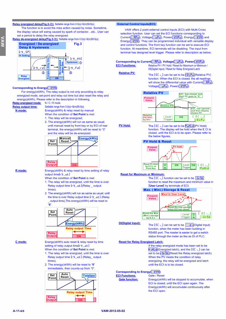
Relay energized delay(Fig.3-): Settable range from 0.0(s)~9(m)59.9(s); External Control Inputs(ECI) The function is to avoid the miss action caused by noise. Sometime,
the display value will swing caused by spark of contactor…etc.. User can set a period to delay the relay energized.
VAW offers 2 point external control inputs (ECI) with Multi-Cross
selection function. User can set the ECI functions corresponding to Current( Apv), Voltage( Vpv), Power( kWpv), Energy( kwh) and Energy( -kwh). They can be programmed individual with versatile display and control functions. The front key function can be set to execute ECI function. At meantime, ECI terminals will be disabling. The input from terminal has designed level trigger. Please refer to description as below,
Relay de-energized delay(Fig.3-): Settable range from 0.0(s)~9(m)59.9(s);
Energized / De-energized Delay & Hysteresis
Fig.3
ON
Hysteresis D
e-e
ne
rgiz
ed
de
lay
tim
e
Hi Setting
Relay Energized
[ry_.sp]
[ry_.hy]
[ry_.rd] [ry_.fd]
En
erg
ized
del
ay t
ime
Corresponding to Current( Apv), Voltage( Vpv), Power( kWpv) ECI Functions: Relative PV / PV Hold / Reset for Maximum or Minimum /
DI(Digital Input) / Reset for Relay Energized Latch Relative PV:
The [ ecI_] can be set to be reLpv(Relative PV) function. When the ECI is closed, the all readings will show the differential value with Current( Apv), Voltage( Vpv), Power( kWpv) .
Corresponding to Energy( kwh)
For energy(±kWh), The relay output is not only according to relay energized mode, set-point and relay out time but also reset the relay and energy(±kWh). Please refer to the description in following,
Relative PV
Relative PV(?PV) by ECI
ON Level Trigger
Present Value
reLpv[ ecI _ ]
ECI_ has closed, and then PV goes to “0”
ECI_ has opened, and then display shows PV
Relative PV
Relay energized mode: N / C / R mode Relay output time: Settable range from 0.0(s)~9(m)59.9(s)
N mode: Energy(±kWh) & relay reset by manual When the condition of Set Point is met:
1. The relay will be energized; 2. The energy(±kWh) will run as same as usual,
until manual reset by front key or by ECI of rear terminal, the energy(±kWh) will be reset to “0” and the relay will be de-energized.
PV Hold: The [ ecI_] can be set to be pVhld(PV Hold)
function. The display will be hold when the E CI is closed, until the ECI is to be open. Please refer to the below figures,
Set Point
Relay Output ON
Energy(kWh)Manual Reset
PV Hold & Reset
Present Value
Reset PV Hold by E.C.I. or Front Key
ON
Level Trigger
ON ON
PV Hold
pVhld[ ecI_ ]
R mode: Energy(±kWh) & relay reset by time setting of relay output time[ry_.ot]
Reset for Maximum or Minimum: When the condition of Set Point is met:
1. The relay will be energized, until the time is over Relay output time [ry_.ot](Relay _ output times).
2. The energy(±kWh) will run as same as usual; until the time is over Relay output time [ry_.ot] (Relay _ output time),The energy(±kWh) will be reset to “0”.
The [ ecI_] function can be set to be Mrst function to reset the maximum and minimum value in [User Level] by terminals of ECI.
Max. ( Mini.) Storage & Reset
Reset the max storage when ECI has closed
Reset the Max. (Mini.) storage
by E.C.I.
ON
Level Trigger
Maxi in User Level Present
Value
Mrst[ ecI _ ]
ON
Auto Reset
Relay output Time
Energy(kWh)
Set Point
Relay Output
DI(Digital Input):
The [ ecI_] can be set to be di(Digital Input) function, when the meter has been building in RS485 port. The master is easier to get a switch status through the meter as like as DI of PLC.
C mode: Energy(±kWh) auto reset & relay reset by time setting of relay output time[ry_.ot]
Reset for Relay Energized Latch: If the relay energized mode has been set to be
hIhld(Energized latch), and the [ ecI_] can be set to be rYrst(Reset the Relay energized latch). When the PV meets the condition of relay energizing, the relay will be energized and latch until the ECI is to be closed.
When the condition of Set Point is met: 1. The relay will be energized, until the time is over
Relay output time [ry_.ot] (Relay_ output times).
2. The energy(±kWh) will be reset to “0” immediately, then counts-up from “0”.
ON
Relay Output
Set Point
Auto Reset Totalizer
Relay output Time
Corresponding to Energy( kwh) ECI Functions: Gate / Reset Gate function: Energy(±kWh) will be stopped to accumulate, when
ECI is closed, until the ECI open again. The Energy(±kWh) will accumulate continuously after the ECI open.
CS
M-3
21S
VA
W
CS
M-3
21S
C
SM
-C
SM
-C
SM
-321
S
CS
M-3
21S
C
SM
-C
SM
-C
SM
-321
S
CS
M-
CS
M-3
21S
VAW-2012-05-02 A-11-7/9
Gate for Totalizer(Energy)
Totalizer (Energy)
Gate by ECI ON
Level Trigger ON ON ON gate
[ ecI_]
Output high corresponds to display High: Setting the Display value high to versus output
Reset Function: Energy(±kWh) will be reset to “0”, when ECI is closed, until the ECI open again. The Energy(±kWh) will accumulate from 0 after the ECI open.
Reset for Totalizer(Energy) Reset by ECI
Edge Trigger ON
ON ON
Totalizer (Energy)
reset[ ecI_]
Fine Zero & Span Adjustment: Users can get Fine Adjustment of analogue output by front key on the
meter. Please connect standard meter to the terminals of analogue output. To press the front key(up or down key) of meter for adjusting and checking the output.
Fine Zero Adjustment: Settable range: -38011~27524; Fine Span Adjustment: Settable range: -38011~27524; High Limited: Settable range: 0.00~110.00% of output High; User can set the high limit of output to avoid
destroying the receiver or protection system. Debouncing time: The function is for avoiding noise signal to into the meter. And The basic period is 8 mseconds. It means you set the number that has to multiply 8 mseconds. For example: [debnc] set to be 5, it means 5 x 8mseconds = 40 mseconds
Set Scaling: [ lOsc]: )00, [ hIsc]: 19(99; Output: [ aOls]: 5)00 (Display value Low),
[ aOhs]: 15)00 (Display value High); [ aOlmt]: 8)00%( of Output Range)
0.00% 100.00% 50.00%
OUTPUT
Ao.LMt: 80.00%
80.00%
SCALE
19(99 [ hIsc]
)00 [ lOsc]
10)00
5)00 [ aOls]
15)00 [ aOhs]
[ aOlmt]
Pulse Output(optional)
The meter offers a pulse output corresponding to energy(±kWh). It’s a popular application to connection a DI of PLC to manage the power consumption. The pulse output is 1000Hz maximum, and 50% duty cycle(0.5msec. minimum).
Pulse divider: Settable range from 1~9999. RS 485 communication(option) plSdv set to be 1: It will output 1 pulse,
when energy(±kWh) increases “1Count”. Ex: It will output 1 pulse, when energy from 12345.678 increase to 12345.679,
plSdv set to be 1000: It will output 1 pulse, when energy(±kWh) increases “1000Count”. Ex: It will output 1 pulse, when energy from 12345.678 increase to 12346.678.
VAW supports Modbus RTU mode protocol to be used as Remote Terminal Unit (RTU) for monitoring and controlling in a SCADA (Supervisor Control And Data Acquisition) system. The baud rate can be up to 38400 bps. It's not only can be read the measured value and DI (external control inputs) status but also controls the relays output (DO) by RS485 communication ports.
VAW APPLICATION FOR RS485 WRINTING
RS 485 Modbus RTU Mode (up to 38400bps)
RS485 wiring 1.2KM maximumTerminate Resistor:
ENT/FN
P L S C O M E C I 1 E C I 2 mwh kwh MK kw W
WH
ENT/FN
P L S C O M E C I 1 E C I 2 mwh kwh MK kw W
WH
Analogue output(option)
Please specify the output type either a 0~10V or 4(0)~20mA in ordering. VAW offers one analogue output with Multi-Cross selection function. User can program the output to correspond Current ( Apv), Voltage( Vpv), Power( kWpv), Energy( kwh) and Energy( -kwh), and also the output low and high can be programmable which it's related to various display values easier in [ ao group]. Reverse slope output is possible by reversing point positions. Please refer to the detail description as below,
Power Saving Function
For the power saving, VAW has built an innovation timer that can be set a time to switch down the light and power of LED. It meets green power idea to build a low consumption meter in a green power system.
Output range corresponds to various display values: Programmable range:
Power Saving Time: Settable from 0.0~9(M):59.9(S) The LED will be darker and power consumption will be less, after user
didn’t push the front key for over the setting of power saving time[Psave]. The power consumption will be less than 40% of rated.
Output low corresponds to display Low:
Setting the Display value Low to versus output range Low(as like as 4mA in A4-20).
CS
M-3
21S
V
AW
C
SM
-321
S
CS
M-
CS
M-
CS
M-3
21S
C
SM
-321
S
CS
M-
CS
M-
CS
M-3
21S
C
SM
-C
SM
-321
S
VAW-2012-05-02 A-11-8/9
FRONT PANEL:
ENT/FN ? ? ?
EC I1 ECI2 V R L1 COM kwh RL2 RL 3 RL 4 A
kW
Measuring value display for Voltage
ECI status indication
Operating Key
RL/Pulse outputsstatus indicationEngineer unit for VoltCommunicationStatus indication
Engineer unit for Energy
Engineer unit for Current
Engineer unit for Power
Measuring value display for Current
Mathematic value display for Power
There are two row displays in VAW to show all parameter in 5 pages. The description as below,
Number screen
Up row: : 0.28”(0.71cm) red high-brightness
LED
Down row: 0.28”(0.71cm) green high-brightness LED
Pages scroll: 5 pages switchable by front
Up/
Down key to show
all parameters
The voltage and current display range are 5 digits. There are 4 digits voltage display in page 1 and 4 digits current display in page 2, due to the voltage and current display in 10 digits limited.
Page 1 for Voltage(4 digits display), Current(5 digits) and Power(kW)
ENT/FN ? ? ?
ECI1 ECI2 V RY1 COM kwh RY2 RY3 RY4 A
kW
Page 2 for Voltage(5 digits), Current(4 digits) and Power(kW)
ENT/FN ? ? ?
ECI1 ECI2 V RY1 COM kwh RY2 RY3 RY4 A
kW
Page 3 for Import Energy and Power(kW)
ENT/FN ? ? ?
ECI1 ECI2 V RY1 COM kwh RY2 RY3 RY4 A
kW
Page 4 for Export Energy and Power(kW)
ENT/FN ? ? ?
ECI1 ECI2 V RY1 COM kwh RY2 RY3 RY4 A
kW
Page 5 for Run Hour and Power(kW)
ENT/FN ? ? ?
ECI1 ECI2 V RY1 COM kwh RY2 RY3 RY4 A
kW
I/O Status Indication
Relay Energized: 4 square red LED
RL1 display when Relay 1 energized;
RL2 display when Relay 2 energized;
RL3 display when Relay 3 energized;
RL4 display when Relay 4 energized;
External Control Input Energized: 2 square green LED
ECI1 display when E.C.I. 1 close(dry contact)
ECI2 display when E.C.I. 2 close(dry contact)
RS485 Communication: 1 square orange LED
COM will flash when the meter is receive or send data, and
COM flash quickly means the data transient quicker.
Pulse Output: 1 square red LED
PLS will flash when the pulse is output according to the accumulation of energy.
Stickers: Each meter has a sticker what are functions enclosure.
Functions stickers
Relay energized
H H HH Energized
H i Hi Energized
L o Lo Energized
L L LL Energized
D O RS485 Energized
Hi. H Hi Energized & Latch
Lo. H Lo Energized & Latch
ECI functions:
PV Hold
Relative PV
Digital Input
Maximum or Minimum Reset
Reset fo Relay Latch
Operating Key: 4 keys for
Enter(Function) /
Shift(Escape) /
Up key /
Down key
Pass Code: Settable range:0000~9999; User must key-in the exactly pass code for access to [Programming Level]. Otherwise, the meter will return to measuring page. If user forgets the pass code, please contact with your service window.
Function Lock: There are 4 levels programmable.
none(None): no lock at all. User can access to all level for checking and setting.
user(User Level): User Level lock. User can access to User Level for checking, but can not setting.
eng(Programming Level): Programming level lock. User can access to programming level for checking, but can not setting.
all(ALL): All lock. User can access to all level for checking but can not setting.
Basic/Advance:
In the programming level, the meter shows only general functions for basic programming in each group. There are advance functions has been hidden in advnc (advance). User can set the advnc in [ prog]of each group to show all functions.
CS
M-3
21S
VA
W
CS
M-3
21S
C
SM
-C
SM
-C
SM
-321
S
CS
M-3
21S
C
SM
-C
SM
-C
SM
-321
S
CS
M-
CS
M-3
21S
VAW-2012-05-02 A-11-9/9
ERROR MASSAGE BEFORE POWER ON, PLEASE CHECK THE SPECIFICATION AND CONNECTION AGAIN.
SELF-DIAGNOSIS AND ERROR CODE:
DISPLAY DESCRIPTION REMARK
ovfl Display is positive-overflow (Signal is over display range) (Please check the input signal)
-ovfl Display is negative-overflow (Signal is under display range) (Please check the input signal)
ovfl ADC is positive-overflow (Signal is higher than input 120%) (Please check the input signal)
-ovfl ADC is negative-overflow (Signal is lower than input -120%) (Please check the input signal)
eep
fail EEPROM occurs error (Please send back to manufactory for repaired)
aiCng
pv Calibrating Input Signal do not process (Please process Calibrating Input Signal)
aic
fail Calibrating Input Signal error (Please check Calibrating Input Signal)
aoCng
pv Calibrating Output Signal do not process (Please process Calibrating Output Signal)
aoc
fail Calibrating Output Signal error (Please check Calibrating Output Signal)
OPERATING KEY *Please access to the Programming Level to check and set the parameters when users start to run the meter
Operating Key: 4 keys for
Enter(Function) /
Shift(Escape) /
Up key /
Down key
The meter has designed operation similar as PC's and Enter . In any page, press
key means "enter" or "confirm setting", and
press
key means "escape( Esc )" or "shift".
In Programming Level, the screen will return to Measuring Page after do not press any key over 2 minutes, or press
for 1 second.
Function Index Setting Status
(=
)
Enter/Fun key
(1) In any page, press
to access the level or function index
(2) From the function index to access setting status
(3) Setting Confirmed, save to EEProm and go to next
function index
(= )
Shift key
(1) In measuring page, press
for 1 second to access user level.
(2) In function index, press
for 1 second to go back upper level.
(3) In function group index, press
for 1 second to go back
measuring page
(4) In setting status, press
to Shift the setting position.
(5) In setting status, press
for 1 second to abort setting
and go back this function index.
(= )
Up key
(1) In function index, press
to go back to previous function
index
(2) In setting status for function, press
to select function
(3) During number Setting, press
can roll the digit up
(= )
Down key
(1) In Function Index Page, press
will go to the next Function
Index Page.
(2) In setting status for function, press
to select
function
(3) During number Setting, press
can roll the digit
down.
CS
M-3
21S
V
AW
C
SM
-321
S
CS
M-
CS
M-
CS
M-3
21S
C
SM
-321
S
CS
M-
CS
M-
CS
M-3
21S
C
SM
-C
SM
-321
S
VA
W –
201
2-0
5-02
OPERATING DIAGRAM (The detail description of operation, please refer to operating manual.)