This software is used for 2D design and calculation of 2D and 2.5D toolpaths for cutting parts on a CNC Router. The software can import 2D designs from other programs such as FormZ, Rhino and Illustrator, but also includes a full set of drawing and editing tools with advanced layout options. In this tutorial, we will cover basic toolpathing of 2D designs for cutting parts on the CNC. 1. Export your file from the program you created it in as a .dxf or .dwg - Make sure your units are in inches and that drawing is correctly scaled. Save it to a thumb drive, Google Drive or e-mail it to yourself. 2. Open VCarve Pro. Click the “Open an existing file” button and select your file. 3. In the Job Setup column on the left, you will type in the correct settings for your part(s). Job Size: Type in the X & Y dimensions of your material. Always give your design at least a 1“ border of buffer material on all sides. The max material size for our CNC is X = 48” and Y = 96” Material (Z): Make sure the top dot is clicked for Z Zero and type in the correct thickness of your material. XY Datum Position: Make sure the dot at the bottom left corner is clicked. Uncheck “Use Offset” and set the X and Y positions to zero. VCarve Pro
Transcript
This software is used for 2D design and calculation of 2D and 2.5D toolpaths for cutting parts on a CNC Router. The software can import 2D designs from other programs such as FormZ, Rhino and Illustrator, but also includes a full set of drawing and editing tools with advanced layout options.
In this tutorial, we will cover basic toolpathing of 2D designs for cutting parts on the CNC.
1. Export your �le from the program you created it in as a .dxf or .dwg - Make sure your units are in inches and that drawing is correctly scaled. Save it to a thumb drive, Google Drive or e-mail it to yourself.
2. Open VCarve Pro. Click the “Open an existing �le” button and select your �le.
3. In the Job Setup column on the left, you will type in the correct settings for your part(s).
Job Size: Type in the X & Y dimensions of your material. Always give your design at least a 1“ border of bu�er material on all sides. The max material size for our CNC is X = 48” and Y = 96”
Material (Z): Make sure the top dot is clicked for Z Zero and type in the correct thickness of your material.
XY Datum Position: Make sure the dot at the bottom left corner is clicked. Uncheck “Use O�set” and set the X and Y positions to zero.
VCarve Pro
Units: Make sure inches is selected. Design Scaling: Uncheck “Scale design with job size
4. Click ”okay”.
5. The screen should look like the image below. On the left are various options for File Operations, 2D View Control, Creating Vectors, and Transforming and Editing Objects.
Hovering your cursor over each icon will give you a description of what the tool does. If you need to move, rotate, scale or edit the vectors in your �le, now is the time to do it.
6. When your �le is ready to be toolpathed, click the Toolpaths tab on the top right corner of the screen.
By clicking the pushpin icon, you can keepthe Toolpaths box pinned open on the screen.
In this tutorial we will review the followingToolpath Operations:
Pro�le- Allows you to machine around thepro�le geometry of a part.
Pocket- Cleans out an enclosed area of apart at a speci�cally set depth.
You are welcome to explore other ToolpathOperations options depending on yourcutting needs.
Pocket Toolpaths
Pocket cuts should always be done before Pro�le cuts. This is because your material has the most surface area and stability on the vacuum bed so you minimize the risk of your material moving when clearing out big areas.
1. Select the �rst shape or set of shapes that you would like to apply a pocket toolpath of a single depth to. To do this, simply click on the shape in the image area of the screen. To select multiple shapes at once, hold down the shift key as you click. When a shape is selected, it will be denoted by a dashed pink line.
Note- If you are going to be pocket cutting di�erent shapes at various depths, you must create separate toolpaths for each shape.
2. Once you have all the shapes you’d like selected, click on the Pocket Toolpath icon.
Set the Start Depth to zero and your Cut Depth to the desired depth. The Cut Depth MUST be less than the thickness of your material! Uncheck Show advanced toolpath options.
Click the Select... button to change your tool bit.
In the Tool Database, select the bit you are using. It is recommended that an End Mill is used for pocket cuts. Here you also have the option to adjust:
Pass Depth: The general rule is that your pass depth should never be more than half diameter of your bit. So if your bit is .25”, your pass depth should be .125”
Stepover: -The stepover should be between 1/3 and 1/10 of the tool diameter.-Use a larger stepover, in the 1/5 to 1/3 range, for soft materials that cannot hold detail well.-Use a smaller stepover, in the 1/5 to 1/10 range, for hard materials or materials that can hold signi�cant detail.-Use the largest tool that will allow you to machine your geometry.
Feeds and Speeds:The spindle speed should be set to 18,000 rpm or less.In general, the plunge rate should be roughly half of the feed rate.
When your bit settings are correct, click “Okay” and continue to adjust your settings in the Pocket Toolpath dialog box.
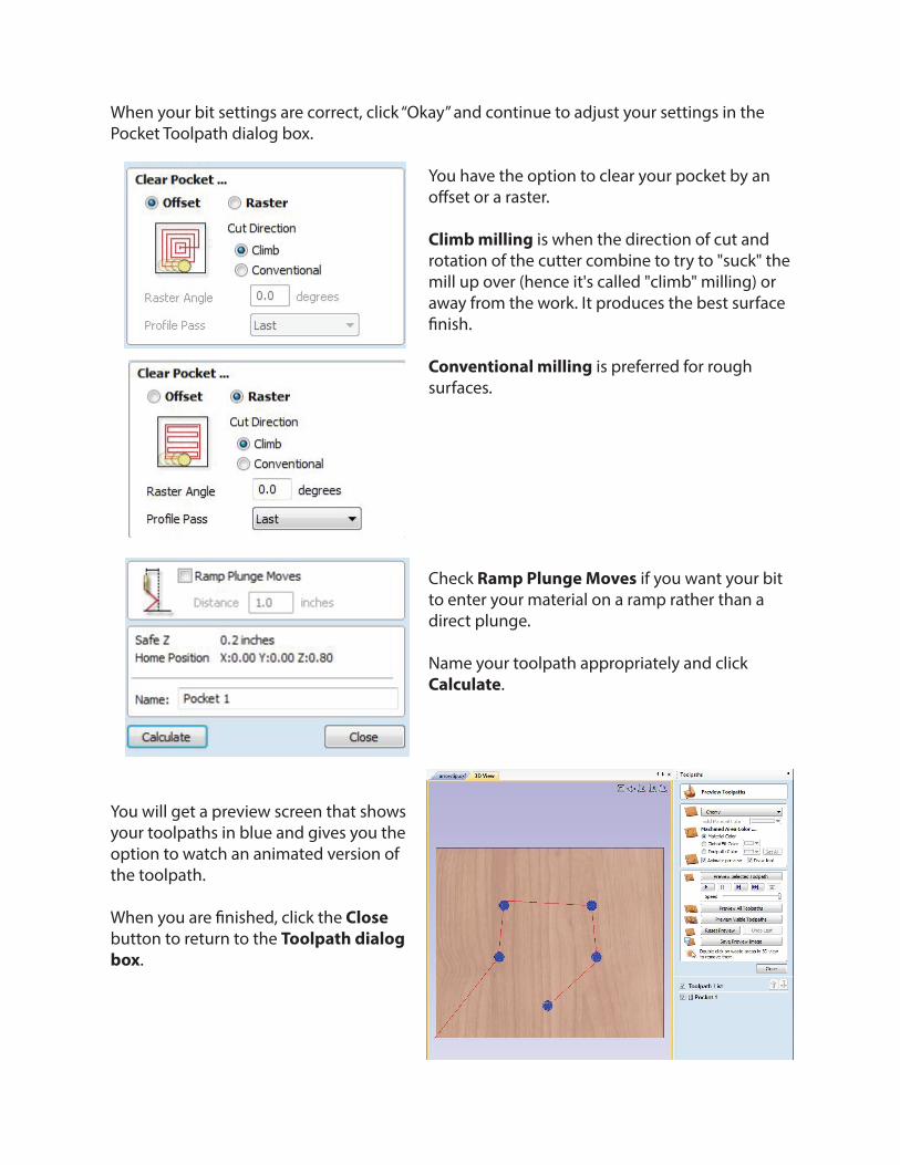
You have the option to clear your pocket by an o�set or a raster.
Climb milling is when the direction of cut and rotation of the cutter combine to try to "suck" the mill up over (hence it's called "climb" milling) or away from the work. It produces the best surface �nish.
Conventional milling is preferred for rough surfaces.
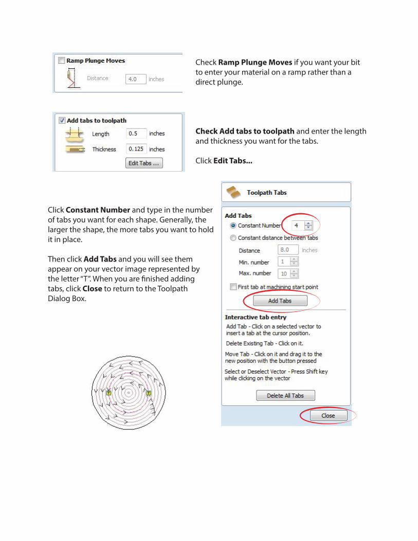
Check Ramp Plunge Moves if you want your bit to enter your material on a ramp rather than a direct plunge.
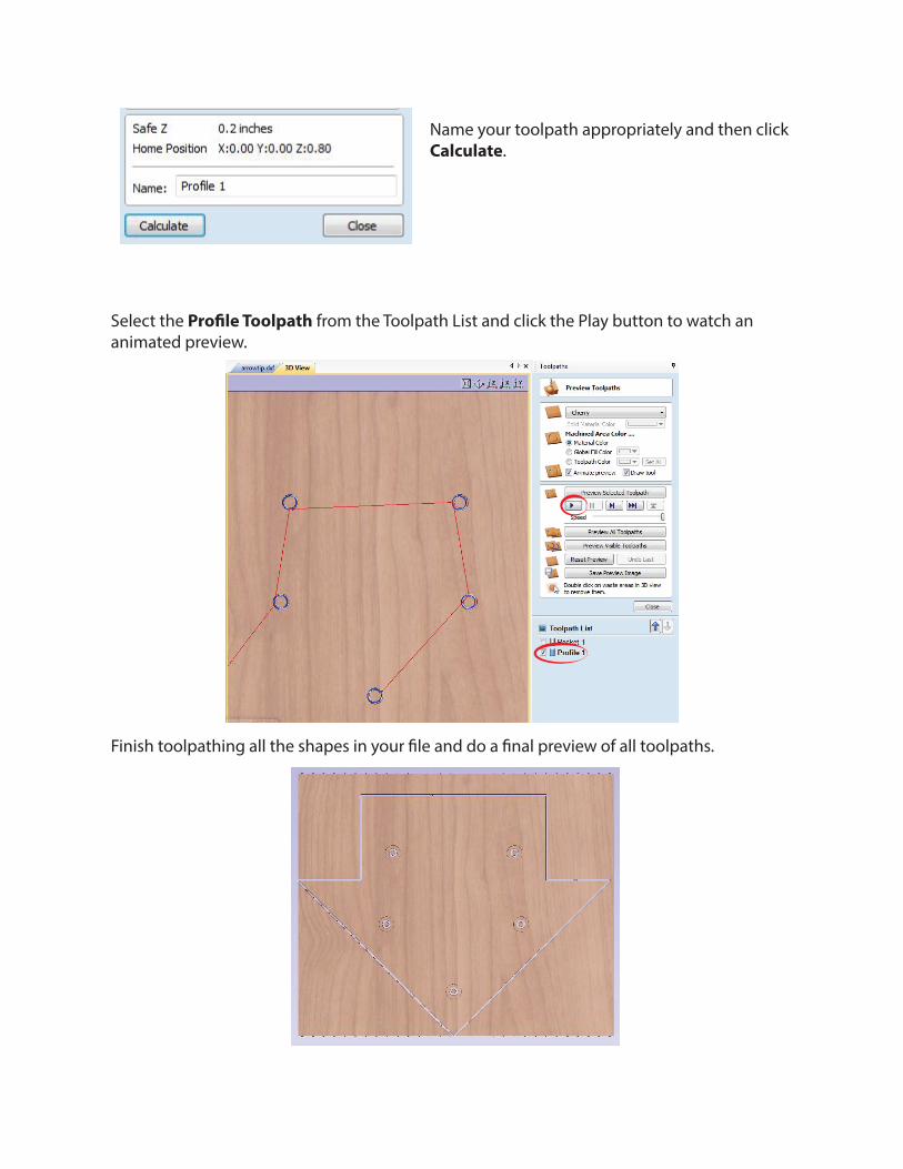
Name your toolpath appropriately and click Calculate.
You will get a preview screen that showsyour toolpaths in blue and gives you theoption to watch an animated version ofthe toolpath.
When you are �nished, click the Closebutton to return to the Toolpath dialogbox.
Pro�le Toolpaths
To get out of 3D view and return to your vector image, click the .dxf tab in the top left corner of the image area.
1. Select the �rst shape or set of shapes that you would like to apply a pro�le toolpath to. To do this, simply click on the shape in the image area of the screen. To select multiple shapes at once, hold down the shift key as you click. When a shape is selected, it will be denoted by a dashed pink line.
2. Once you have all the shapes you’d like selected, click on the Pro�le Toolpath icon.
Set your Start Depth at zero and you Cut Depth to the thickness of your material plus an extra .05” to cut a bit deeper and into your spoil board. So if your material is .25” you’ll want a Cut Depth of .255”
Click Select... to change your tool bit.
In the Tool Database, select the bit you are using. It is recommended that an End Mill is used for pro�le cuts. Here you also have the option to adjust:
Pass Depth: The general rule is that your pass depth should never be more than half diameter of your bit. So if your bit is .25”, your pass depth should be .125”
Stepover is not relevant for pro�le cuts.
Feeds and Speeds:The spindle speed should be set to 18,000 rpm or less.In general, the plunge rate should be roughly half of the feed rate.
When your bit settings are correct, click “Okay” and continue to adjust your settings in the Pocket Toolpath dialog box.
Select from Outside/Right, Inside/Left or On depending on what side of the path you want the cut to be made on.
Climb milling is when the direction of cut and rotation of the cutter combine to try to "suck" the mill up over (hence it's called "climb" milling) or away from the work. It produces the best surface �nish.
Conventional milling is preferred for rough surfaces.
Check Ramp Plunge Moves if you want your bit to enter your material on a ramp rather than a direct plunge.
Check Add tabs to toolpath and enter the length and thickness you want for the tabs. Click Edit Tabs...
Click Constant Number and type in the numberof tabs you want for each shape. Generally, the larger the shape, the more tabs you want to holdit in place.
Then click Add Tabs and you will see themappear on your vector image represented by the letter “T”. When you are �nished adding tabs, click Close to return to the ToolpathDialog Box.
Name your toolpath appropriately and then click Calculate.
Select the Pro�le Toolpath from the Toolpath List and click the Play button to watch an animated preview.
Finish toolpathing all the shapes in your �le and do a �nal preview of all toolpaths.
Click the Save Toolpaths icon in the Toolpath Operations box.
Make sure everything on your Toolpath Listis selected.
Check the box next to Output all visible toolpaths to one �le
Select Techno-Isel ATC (inch) (*.ncd) as the Post Processor.
Click Save Toolpath(s)... to save to your drive.
You are now ready to load your toolpaths in Techno CNC!