Application and Design The VCD-23 series is a ruggedly built low leakage control damper intended for application in low to medium pressure and velocity systems. A wide range of electric actuators are available. Ratings (See page 4 for specific limitations) Pressure: Up to 5.0 in. wg (1.2 kPa) - pressure differential Velocity: Up to 3000 fpm (15.2 m/s) Leakage: Class 1A @ 1 in. wg (.25 kPa) Class 1 @ up to 5 in. wg (1.2 kPa) Temperature: Up to 250°F (121°C) (Consult Greenheck for higher temperatures) * W & H dimension furnished approximately 1 / 4 in. (6mm) undersize. Shown with optional extension pin and standoff bracket. VCD-23 Low Leakage CONTROL DAMPER Flange Options Opposed Blades Parallel Blades 5 in. 5 in. 1 1/4 in. max. (typical) 1 1/4 in. max. (typical) Blade Operation Installation instructions available at www. greenheck.com. Construction Standard Optional Frame Material Galvanized Steel - Frame Thickness 16 ga. (1.5mm) - Frame Type 5 in. x 1 in. (127mm x 25mm) Channel Single flange, reversed flange, double flange Blade Material Galvanized steel - Blade Thickness 16 ga. (1.5mm) - Blade Type 3V - Blade Seals TPE Silicone Axle 1/2 in. dia. Plated Steel - Axle Bearings Synthetic 304SS Linkage Material Plated Steel - Jamb Seal 304SS - W x H Minimum Size Maximum Size Single Section Multiple Section Inches 6 x 6 48 x 74 Unlimited mm 152 x 152 1219 x 1880 Unlimited Size Limitations Features & Options • Blade seals - pressure activated to produce tighter sealing. • Linkage concealed in the frame • Low profile head and sill are used on sizes less than 17 in. (432mm) • Wide range of electric actuators and manual quadrant available. Factory installation available. • Sleeves available • 5/8 in. - 2 in. (16mm - 51mm) flange available • Retaining angles • Transitions- R and C • Open Close Indicator (OCI) H* W* Single Flange Double Flange Single Reversed Flange 5 in. 5 in. 5 in. 1 1/2 in. (Typical) Shown with optional internally mounted actuator.
Transcript
Application and DesignThe VCD-23 series is a ruggedly built low leakage control damper intended for application in low to medium pressure and velocity systems. A wide range of electric actuators are available.
Ratings (See page 4 for specific limitations)
Pressure: Up to 5.0 in. wg (1.2 kPa) - pressure differential
Velocity: Up to 3000 fpm (15.2 m/s) Leakage: Class 1A @ 1 in. wg (.25 kPa)
Class 1 @ up to 5 in. wg (1.2 kPa) Temperature: Up to 250°F (121°C) (Consult Greenheck for higher temperatures)
* W&H dimension furnished approximately 1/4 in. (6mm) undersize.Shown with optional extension pin and standoff bracket.
VCD-23Low Leakage CONTROL DAMPER
Flange Options
Opposed BladesParallel Blades
5 in. 5 in.
1 1/4 in.max.
(typical)
1 1/4 in.max.
(typical)
Blade Operation
Installation instructions available at www. greenheck.com.
Construction Standard Optional
Frame Material Galvanized Steel -
Frame Thickness 16 ga. (1.5mm)
-
Frame Type5 in. x 1 in.
(127mm x 25mm) Channel
Single flange,reversed flange, double flange
Blade Material Galvanized steel -
Blade Thickness 16 ga. (1.5mm)
-
Blade Type 3V -
Blade Seals TPE Silicone
Axle 1/2 in. dia. Plated Steel
-
Axle Bearings Synthetic 304SS
Linkage Material Plated Steel -
Jamb Seal 304SS -
W x H Minimum Size
Maximum Size
Single Section
Multiple Section
Inches 6 x 6 48 x 74 Unlimited
mm 152 x 152 1219 x 1880 Unlimited
Size Limitations
Features & Options • Blade seals - pressure activated to produce tighter sealing. • Linkage concealed in the frame • Low profile head and sill are used on sizes less than 17 in.
(432mm) • Wide range of electric actuators and manual quadrant
available. Factory installation available. • Sleeves available • 5/8 in. - 2 in. (16mm - 51mm) flange available • Retaining angles • Transitions- R and C • Open Close Indicator (OCI)
H*
W*
Single Flange Double FlangeSingle Reversed Flange
5 in. 5 in. 5 in.
1 1/2 in. (Typical)
Shown with optional internally mounted actuator.
Pressure Drop Data VCD-23This pressure drop testing was conducted in accordance with AMCA Standard 500-D using the three configurations shown. All data has been corrected to represent standard air at a density of .075 lb/ft3 (1.2 kg/m3).Actual pressure drop found in any HVAC system is a combination of many factors. This pressure drop information along with an analysis of other system influences should be used to estimate actual pressure losses for a damper installed in a given HVAC system.
AMCA Test FiguresFigure 5.2 Illustrates a ducted damper exhausting air into an open area. This configuration has a lower pressure drop than Figure 5.5 because entrance losses are minimized by a straight duct run upstream of the damper.
Figure 5.3 Illustrates a fully ducted damper. This configuration has the lowest pressure drop of the three test configurations because entrance and exit losses are minimized by straight duct runs upstream and downstream of the damper.
Figure 5.5 Illustrates a plenum mounted damper. This configuration has the highest pressure drop because of extremely high entrance and exit losses due to the sudden changes of area in the system.
5D 6D
5D
D 4 (W) (H)3.14
5D 6D
5D
D 4 (W) (H)3.14
5D 6D
5D
D 4 (W) (H)3.14
5D 6D
5D
D 4 (W) (H)3.14
5D 6D
5D
D 4 (W) (H)3.14
AMCA Certified Pressure Drop Data VCD-23
Velocity (fpm)Pressure Drop
(in. wg) Velocity (fpm)Pressure Drop
(in. wg) Velocity (fpm)Pressure Drop
(in. wg)
500 0.01 500 0.01 500 0.01
1000 0.05 1000 0.03 1000 0.02
1500 0.11 1500 0.06 1500 0.05
2000 0.19 2000 0.10 2000 0.09
2500 0.29 2500 0.16 2500 0.14
3000 0.41 3000 0.23 3000 0.19
3500 0.55 3500 0.30 3500 0.27
4000 0.72 4000 0.40 4000 0.35
12 in. x 12 in. (305mm x 305mm) 24 in. x 24 in. (610mm x 610mm) 36 in. x 36 in. (914mm x 914mm)
Velocity (fpm)Pressure Drop
(in. wg)
500 0.01
1000 0.03
1500 0.07
2000 0.12
2500 0.18
3000 0.26
3500 0.36
4000 0.47
48 in. x 12 in. (1219mm x 305mm)
Velocity (fpm)Pressure Drop
(in. wg)
500 0.01
1000 0.04
1500 0.08
2000 0.15
2500 0.22
3000 0.32
3500 0.43
4000 0.56
12 in. x 48 in. (305mm x 1219mm)
AMCA 5.2
AMCA 5.3
AMCA 5.5
Velocity (fpm)Pressure Drop
(in. wg) Velocity (fpm)Pressure Drop
(in. wg) Velocity (fpm)Pressure Drop
(in. wg)
500 0.01 500 0.01 500 0.01
1000 0.03 1000 0.02 1000 0.02
1500 0.08 1500 0.04 1500 0.03
2000 0.13 2000 0.07 2000 0.06
2500 0.20 2500 0.11 2500 0.09
3000 0.29 3000 0.16 3000 0.13
3500 0.40 3500 0.21 3500 0.19
4000 0.51 4000 0.28 4000 0.25
12 in. x 12 in. (305mm x 305mm) 24 in. x 24 in. (610mm x 610mm) 36 in. x 36 in. (914mm x 914mm)
Velocity (fpm)Pressure Drop
(in. wg)
500 0.01
1000 0.03
1500 0.06
2000 0.10
2500 0.16
3000 0.22
3500 0.30
4000 0.39
48 in. x 12 in. (1219mm x 305mm)
Velocity (fpm)Pressure Drop
(in. wg)
500 0.01
1000 0.03
1500 0.07
2000 0.12
2500 0.18
3000 0.26
3500 0.36
4000 0.46
12 in. x 48 in. (305mm x 1219mm)
Velocity (fpm)Pressure Drop
(in. wg) Velocity (fpm)Pressure Drop
(in. wg) Velocity (fpm)Pressure Drop
(in. wg)
500 0.03 500 0.03 500 0.02
1000 0.13 1000 0.12 1000 0.10
1500 0.30 1500 0.26 1500 0.22
2000 0.53 2000 0.47 2000 0.40
2500 0.82 2500 0.75 2500 0.62
3000 1.19 3000 1.04 3000 0.90
3500 1.62 3500 1.41 3500 1.23
4000 2.10 4000 1.90 4000 1.62
12 in. x 12 in. (305mm x 305mm) 24 in. x 24 in. (610mm x 610mm) 36 in. x 36 in. (914mm x 914mm)
Velocity (fpm)Pressure Drop
(in. wg)
500 0.03
1000 0.12
1500 0.28
2000 0.49
2500 0.77
3000 1.12
3500 1.53
4000 2.01
48 in. x 12 in. (1219mm x 305mm)
Velocity (fpm)Pressure Drop
(in. wg)
500 0.03
1000 0.12
1500 0.27
2000 0.47
2500 0.75
3000 1.07
3500 1.45
4000 1.91
12 in. x 48 in. (305mm x 1219mm)
5D 6D
5D
D 4 (W) (H)3.14
Greenheck India Pvt. Ltd. and Greenheck Kunshan Co. Ltd. certifies that the model VCD-23 shown herein is licensed to bear the AMCA Seal. The ratings shown are based on tests and procedures performed in accordance with AMCA Publication 511 and comply with the requirements of the AMCA Certified Ratings Programs.The AMCA Certified Ratings Seal applies to Air Leakage and Air Performance ratings.
24
0
12
36
48
60
74
0 12 24 36 48
Damper Width (in.)
Dam
per
Hei
ght
(in.
)
3000fpm
2000fpm
2500fpm
Velocity Limitations
AMCA Certified Leakage Data VCD-23
Air leakage is based on operation between 32°F (0°C) and 120°F (49°C).Tested for leakage in accordance with ANSI/AMCA Standard 500-D, Figure 5.5.Tested for air performance in accordance with ANSI/AMCA Standard 500-D, Figures 5.2, 5.3 and 5.5.
TorqueData are based on a torque of 5.0 in.lb./ft² (0.56 N·m) applied to close and seat the damper during the test.
Greenheck India Pvt. Ltd. and Greenheck Kunshan Co. Ltd. certifies that the model VCD-23 shown herein is licensed to bear the AMCA Seal. The ratings shown are based on tests and procedures performed in accordance with AMCA Publication 511 and comply with the requirements of the AMCA Certified Ratings Programs.The AMCA Certified Ratings Seal applies to Air Leakage and Air Performance ratings.
VCD-23 Leakage Class*
Maximum Damper Width
1 in. wg (0.25 kPa)
4 in. wg(1 kPa)
5 in. wg(1.2 kPa)
48 in. (1219mm) 1A 1 1
*Leakage Class DefinitionsThe maximum allowable leakage is defined by AMCA as the following:• Leakage Class 1A - 3 cfm/ft2 @ 1 in. wg (class 1A is only
defined at 1 in. wg).
• Leakage Class 1 - 4 cfm/ft2 @ 1 in. wg - 8 cfm/ft2 @ 4 in. wg - 11 cfm/ft2 @ 8 in. wg - 12.6 cfm/ft2 @ 10 in. wg
Application Data
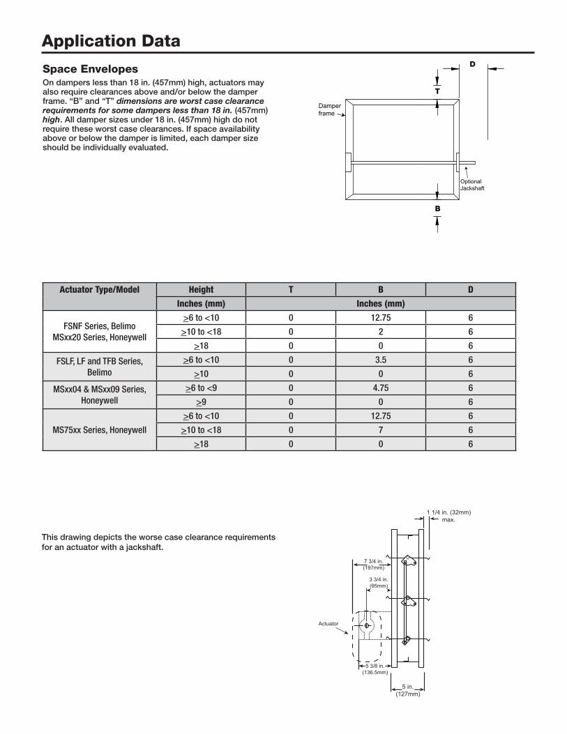
Space EnvelopesOn dampers less than 18 in. (457mm) high, actuators may also require clearances above and/or below the damper frame. “B” and “T” dimensions are worst case clearance requirements for some dampers less than 18 in. (457mm) high. All damper sizes under 18 in. (457mm) high do not require these worst case clearances. If space availability above or below the damper is limited, each damper size should be individually evaluated.
T
B
D
Damper frame
OptionalJackshaft
Actuator Type/Model Height T B D
Inches (mm) Inches (mm)
FSNF Series, Belimo MSxx20 Series, Honeywell
>6 to <10 0 12.75 6
>10 to <18 0 2 6
>18 0 0 6
FSLF, LF and TFB Series, Belimo
>6 to <10 0 3.5 6
>10 0 0 6
MSxx04 & MSxx09 Series, Honeywell
>6 to <9 0 4.75 6
>9 0 0 6
MS75xx Series, Honeywell
>6 to <10 0 12.75 6
>10 to <18 0 7 6
>18 0 0 6
1 1/4 in. (32mm)max.
3 3/4 in.(95mm)
5 3/8 in.(136.5mm)
5 in. (127mm)
Actuator
7 3/4 in.(197mm)
This drawing depicts the worse case clearance requirements for an actuator with a jackshaft.
Application DataMulti-Section AssemblyDampers larger than the maximum single section size, will be made up of a multiple of equal size sections. Multiple section dampers can be jackshafted together so that all sections operate together as shown below.
NOTE: Dampers larger than 48 in. x 74 in. (1219mm x 1880mm) are not intended to be structurally self supporting. Additional horizontal bracing is recommended to support the weight of the damper and vertical bracing should be installed as required to hold against system pressure.
SpecificationsControl dampers meeting the following specifications shall be furnished and installed where shown on plans and/or as described in schedules.Damper blades shall be 16 ga. (1.5mm) galvanized steel 3V type with three longitudinal grooves for reinforcement. Blades shall be completely symmetrical relative to their axle pivot point, presenting identical resistance to airflow and operation in either direction through the damper (blades that are non-symmetrical relative to their axle pivot point or utilize blade stops larger than 1/2 in. [13mm] are unacceptable). Blade seals shall be TPE. Linkage shall be blade-to-blade concealed in jamb (out of the airstream) to protect linkage and reduce pressure drop and noise.Damper frame shall be 16 ga. (1.5mm) galvanized steel
formed into a structural hat channel shape with reinforced corners to meet 11 ga. (3.1mm) criteria. Bearings shall be corrosion resistant, permanently lubricated, synthetic (acetal) sleeve type rotating in extruded holes in the damper frame for maximum service. Axles shall be square and positively locked into the damper blade. Jamb seals shall be flexible stainless steel compression type to prevent leakage between blade end and damper frame.The damper manufacturer’s submittal data shall certify all air leakage and air performance pressure drop data is licensed in accordance with the AMCA Certified Ratings Program for Test Figures 5.2, 5.3 and 5.5. Damper air performance data shall be developed in accordance with the latest edition of AMCA Standard 500-D.Basis of design is Greenheek's model VCD-23.