56
Indoor Vacuum Circuit Breaker - Type VD4 / VD4E Instruction for Installation, Operation & Maintenance

Indoor Vacuum Circuit Breaker - Type VD4 / VD4E
Instruction for Installation, Operation & Maintenance

Contents Pg. No.
A. General
B. Design
C. Installation & Commissioning
D. Operation & Maintenance
E. Drawings & Spare Parts Reference
Instruction for Installation, Operation & Maintenance of Vacuum Circuit Breaker Type VD4 / VD4E
3
5
9
13
17
33

4

A. GENERAL Pg. No.
Key to type designation
Information on rating plate
Weight of circuit breaker
Handling & storage
Normal operating conditions
Special operating conditions
A. GENERAL
Condition on delivery
Receipt
Unloading
Storage rules & regulations
5
6
7
7
8
8
8
8
8
8
8

A. GENERAL
The Vacuum Circuit Breaker type VD4E /
VD4 are intended for indoor installation in air-
insulated switchboards.
Vacuum circuit breakers are advantageous
to use in distribution networks especially
where there is a high switching frequency in
the working current range and/or where a
certain number of short circuit breaking
operations are expected.
Type VD4 / VD4-E vacuum circuit breakers
are suitable for auto-reclosing, and have
exceptionally high operating reliability and
long life.
The guaranteed technical particulars have
been confirmed by numerous tests in our
collaborators own laboratory & other
independent laboratories of world repute.
Key to type Designation
Vacuum as arc quenching medium
Rated voltage in kV 12, for 12kV
Rated continuous current in Amps.06 for upto 800 Amps. 12 for 1250 Amps.16 for 1600 Amps.
Rated breaking current in kA 13 for 13.1 KA 20 for 20 KA 25 for 26.3 KA
For entry level rated current (up to 800A)
VD4 12 06 25 E
As an example the type designation for VD4 12.06.25E is illustrated below
6

Information on Rating Plate
Type Circuit Breaker VD4 or VD4-E Sr. No. Breaker Production Serial No. Year Year of Manufacture Standard IEC : 60056 / 62271-100 Rated voltage 12kV Frequency 50Hz Insulation level 28 / 75kVp Normal current 800 or 1250 or 1600 Amps Short circuit breaking current 13.1 or 20 or 26.3 kADuration of short circuit 3sec. Short circuit making current 63kA or 80kA Operating sequence O-0.3S-CO-3min-CO Weight 100Kgs for VD4E or 125Kgs for Vd4Auxiliary voltage: Closing coil Rated voltage for closing coil Opening coil Rated voltage for opening coil Motor Rated voltage for spring charging motor Instruction Manual 1VDU09001-YN
Break-up of the weight of the circuit breaker
Component VD4E VD4
3 Poles (Kgs) 35 50
Operating mechanism (Kgs) 50 60
Structure (Kgs) 15 15
Total(Kgs) 100 125
7
Weight in Kgs.

A. GENERAL
General
The Medium Voltage circuit breakers are
delivered firmly screwed to the floor of
their containers or crates and must always
be transported or stored in an upright
position. The circuit breaker is transhipped
in packing in the open (OFF) position and
with the closing spring discharged.
Condition on delivery
The factory assembled circuit breakers are
checked at the works for completeness of
the equipment and simultaneously
subjected to a routine test in accordance
with the IEC publication 56, thus verifying
their correct structure and function.
Receipt
Each delivery is to be checked on receipt
for :
- Completeness and correctness (Check
against order and delivery documents).
- Any possible damage in transit and
material losses.
Abnormality, if any, must be notified
immediately to:
-The manufacturer
-The forwarding agent and the
insurance company.
-The responsible claims inspector
according to the insurance
certificate for the purpose of making
out a damage or loss Certificate.
Unloading
Unloading of the package units must only
be carried out with a crane, fork lift truck
and / or transport trolley jack.
Storage Rules and Regulations
The material shall be stored in a well
ventilated storage room and to be protected
against dirt, damage and water ingression.
The original packing can be used for storage,
however, without the plastic sheet.
Normal Operating Conditions
The vacuum circuit breakers of type VD4 are
basically suitable for normal operating
conditions for indoor Switchgear and
switchboard in accordance with IEC
publication 694.
The following limit values apply :
Ambient temperature :
Maximum + 40°C
Maximum 24 hour average + 35°C
Minimum - 5°C
(according to "minus 5 indoor " class)
Humidity :
Maximum average relative humidity
measured over 24 hours: 95%
Maximum average relative humidity
measured over 1 month: 90%
Maximum site altitude : <1000m
(above MSL)
Note: The ambient air should not be
excessively contaminated by dust, smoke,
corrosive or combustible gases, vapours
or salt.
Special Operating Conditions
Special operating conditions are to be agreed
on by the manufacturer and user.
The manufacturers must be consulted in
advance about each special operating
condition.
Site altitude over 1000 m :
- Allow for the reduction in the dielectric
strength of the air.
Increased ambient temperature :
- Current carrying capacity is reduced.
- Provide additional ventilation for heat
dissipation.
Climate :
- To minimize risk of corrosion avoid areas
with:
- With high humidity
- Major rapid temperature fluctuations.
- Implement preventive measures (e.g.
electric heaters) to preclude condensation.
....
.
.
.
.
.
.
Handling & Storage
.
8

B. DESIGN
B. DESIGN Pg. No.
General features
Structure & function
Constructional details
Pole assembly
Operating mechanism
Truck assembly
Working principle of pole assembly
- Contact operation
- Principle of interruption
9
10
10
10
10
10
10
11
11
11

B. DESIGN
General Features
The vacuum interrupter in VD4 / VD4E circuit
breakers are designed such that the contact
speed, travel and mass is low, subsequently
low spring forces are sufficient for operation.
The breaker operating mechanism is thus
extremely low in wear, and the maintenance
requirement are accordingly negligible.
Structure and Function (Drg.2 & 3, pg.no. 43 & 44)
The poles, which are constructed in column
form, are mounted on the bracket shaped rear
part of the breaker mechanism housing 1. The
live parts of the breaker poles are located in
the insulating material pole tubes 12 and
protected from impact and other external
influences.
With the breaker closed, the current path
leads from the breaker upper terminal 13 and
a chamber holder fixed in the pole tube to the
fixed contact 15.2 in the vacuum interrupter
15, then via the moving contact 15.3 and the
flexible conductor / roller contact 16.2 to the
breaker lower terminal 14. The switching
motion is effected by means of the insulated
coupling rod 18 with internal contact pressure
springs 17.
Constructional details
Vacuum circuit breaker type VD4-E / VD4
consists of :
Breaker poles of epoxy resin firmly
holding and protecting the vacuum
interrupter assembly from impacts and
other external influences.
A spring charged operating mechanism .
A truck assembly with relevant interlock
features.
conductor (V1008). The moving contact of
the interrupter is connected to the operating
mechanism through a Operating stud (V1003/
2003). The disc springs inside the operating
studs exerts the required contact pressure on
the contacts.
Operating Mechanism
The operating mechanism consists of :
A spring charging unit which can be
charged manually or electrically by a
geared motor.
Mechanical indicator showing spring
charged / discharged condition.
Indicator for open / close position of the
circuit breaker.
Closing / tripping magnet for performing
closing / opening operation of the circuit
breaker electrically.
Operation counter showing total number
of operations performed by the breaker.
Motor cut-off switch and auxiliary switch.
Switch for annunciation and control of
auxiliary circuits.
Optional items like under voltage trip
additional trip coil and blocking magnet.
The spring charging mechanism ensures that
the breaker can perform O-C-O operation if it
is closed and charged. The breaker can
perform C-O operation if it is open and
charged. As soon as the energy is removed
from the spring charging mechanism, the NO
contact of the cut-off switch is opened
interrupting the motor circuit. The spring
charging mechanism can also be recharged
manually by means of a charging handle.
Truck assembly (Drg.1, pg.no. 41)
This assembly consists of :
Frame assembly
Wheel rack assembly
Automatic secondary plug & socket
assembly.
Interlocking rod assembly
Bottom plate assembly
Emergency trip assembly
The above assembly provides the
following features :
.
..
.
Pole assembly (Drg.4A & 4B, pg.nos. 45)
Pole assembly consists of a vacuum
interrupter (V1002 / V2002) mounted
firmly in the Pole housing
(V1001/ V2001) made out of epoxy resin.
The interrupter is firmly fixed on the top
connection bar and the moving contact
of the interrupter is connected to the
bottom connection bar with a Flexible
.
.
.
.
..
.
...
...
10

Closed breaker can not be moved from test
to service position or vice-versa.
Breaker can not be closed when it is in
intermittent position.
The movement of the selector is blocked
when the breaker is in the closed condition.
A closed breaker can not be pushed into
test position from withdrawn position.
.
.
.
.
operating levers driven by the individual
cam discs mounted on the common shaft.
Very high contact pressure is maintained
through the spring washer assembly housed
in a operating stud.
Principle of interruption
Due to the extremely low static interrupter -4 -8 chamber pressure of 10 to 10 in mbars,
only a relatively small contact gap is required
to achieve a high dielectric strength. The arc
is extinguished on one of the first natural
current zeros.
Due to small contact gap and high
conductivity of the metal vapour plasma, the
arc drop voltage, and additionally, due to short
arcing time, the associated arc energy, are
extremely low, which has advantageous
effects on the life of the contacts and thus on
that of the vacuum interrupters.
Working Principle of pole assembly
Contact operation
The closing and opening operations can be
carried out by means of the energy stored
in the operating mechanism. One common
spiral spring is used to carry out the closing
and opening operation of the breaker and
three individual compression spring
assemblies are used to assist the opening
operation of the three poles.The movement
/ stroke of the moving contact of the
vacuum interrupter is achieved through the
11

12

C. INSTALLATION & COMMISSIONING
Preparatory work
Tools & accessories
Technical documents
Erection
Electrical connections
High voltage connections
Low voltage connections
Earthing
Commissioning
General checks
Table 1: Precommissioning checks
Functional checks
Final Checks
Handing over
C. INSTALLATION & COMMISSIONING Pg. No.
13
14
14
14
14
14
14
14
14
15
15
15
16
16
16

C. ERECTION & COMMISSIONING
Erection
Preparatory work
The following items should be held in
readiness before the circuit breaker is placed
in position.
Tools and Accessories
- Torque wrenches Range 0 -150Nm
- Ratchet
- Torque screw drives Range 0 - 10Nm
- Extensions Range 0 - 250mm
- Allen keys size - 3 - 9 (1set)
- Open end & ring spanners
size - 5-32 (1set)
- Screw drivers size - 00-5 (1set)
- Flat nose plier with side cutter
size - 120mm (1no)
- Circlip plier (1no)
- Extractor plier (1no)
- Loctite 290,270,
- Grease ISOFLEX TOPAS NB 52
- Cleaning cloth
- Special tools
- Main shaft rotation tool.
- Special screw driver for torsion
spring.
- Special socket for M6 nylock nut
assembly.
Technical documents
Assembly drawings.
Customer’s order reference drawings.
Circuit diagram.
Dimensional drawings.
Erection
For erection of switchgear cubicle, refer the
relevant instruction manual for the particular
cubicle type.
When all the panels are erected correctly,
check that the cubicle fronts are in line and
that the cubicle doors with the interlocking
devices work correctly.
The movement of all the handles should be
easy and smooth.
Put the breaker into the cubicle and check
the following :
..
..
.
.
.
Free movement of the breaker from
withdrawn position to Test and from
Test to Service and vice versa.
Proper engagement of secondary
plug and socket.
Proper functioning of various interlocks.
Proper engagement of earthing
contacts.
Proper engagement of connection bars
with the cubicle contacts.
.
.
.
.
Electrical connection
High voltage connections
Clean and degrease the silver plated
contacts with a clean, non-linting linen
cloth and cleaning agent. Let dry well,
With a linen cloth. Apply a thin film of
contact grease / Vaselene to the contact
surfaces.
The high voltage connections are
provided by means of assembly of
connection bars on the breaker side and
finger pocket assembly on the cubicle
side. Cleaning and degreasing are to be
carried out in the same manner.
Low voltage connections
The auxiliary circuit connection shall be
checked as per the relevant schematic
diagram for correctness.
Earthing
The permanent earthing is provided by
means of earthing busbar in all the
switchgear cubicles. There are terminals
for connecting external earthings to this
busbar. The stations earthing terminal is
connected only in the end cubicle. Each
circuit breaker is provided with earthing
finger contacts mounted on, the top of
the breaker truck. These finger contacts
engage and slide against the wedge
type contact provided in the switchgear
cubicle, which is, in turn, connected to
the cubicle main earth busbar.
Lubricate the earthing contacts on the
breaker truck and cubicle with a thin film
of vaselene or contact grease and
ensure proper contact engagement.
.
14

General procedures
Before putting the circuit breaker into service
carry out the following checks :
Check the tightness of the power
connections on the circuit breaker
terminals.
Check that the value of the supply voltage
for the auxiliary circuit is with in 85% and
110%, of the rated voltage, of the
electrical devices.
Check that no foreign material has got
into the moving parts.
Commissioning
.
.
.
To gain access to the operating
mechanism safely, discharge the closing
springs (by closing & opening the circuit
breaker), then remove the cover of the
operating mechanism.
Check that air circulation in the circuit
breaker installation site is adequate so
that there is no danger of overheating.
Remove the transport caps from the poles,
Ensure that the instruction manual is
available to the operator at all the
times.
Carry out the checks indicated in table
no. 1 :
.
..
.
Carry out a few closing and opening operation NOTE : Connect theundervoltage release with the relative rated auxiliary supply voltage (if provided)
Connect the geared motor for spring charging with the relative rated auxiliary supply voltage. Carry out a few closing and opening operations. . NOTE: Connect the undervoltage release with the relative rated auxiliary supply voltage (if provided)
Connect the undervoltage release with therelative rated auxiliary supply voltage and carry out the circuit breaker closing operation. Disconnect the power supply from the release.
Close the circuit breaker. Connect the shunt opening release with the relative rated auxiliary supply voltage.
Open the circuit breaker. Connect the shunt closing release with the relative rated auxiliary supply voltage.
The operations and the relevant indications occur correctly.
The geared motor recharges the spring after each closing operation.
The circuit breaker closes and the relevant indications occur correctly. The circuit breaker opens and the relevant indication occur correctly.
The circuit breaker opens and the relevant indication occur correctly.
The circuit breaker closes correctly and the relevant indications occur correctly.
SUBJECT OFINSPECTION
PROCEDURE POSITIVE CHECK
1. Manual operating mechanism
2. Motor operated mechanism (if provided)
3. Undertvoltage release (if provided)
4. Shunt opening release
5. Shunt closing release
Table 1: Precommissioning Checks
15
.

SUBJECT OFINSPECTION
PROCEDURE POSITIVE CHECK
6. Auxiliary contacts in the operating mechanism
7. Test service position limit switch operation
8. Insulation resistance
9. Functions of various interlocks
Insert the auxiliary contacts into suitable signaling circuits. Carry out a few closingand opening operations of the circuitbreaker.
Move the breaker from test to service few times.
With 2500V Meggar, measure insulation resistance between phases and phase to earth.
Check interlock functions
Signals occur correctly
Test service position indications occur correctly.
The insulation resistance should be at least 50 Mega Ohm & if the value is less find out the cause.
Interlock should function correctly.
Functional checks must only be carried out
when:
The circuit breaker is disconnected from
the high voltage network and is correctly
earthed.
The breaker mounting screws are well
tightened.
Any foreign material that is likely to
disturb operations is removed.
The functional check is to be performed
in accordance with the instructions for
operation and maintenance of the
Functional checks Operating mechanism and to be
repeated for every remote controlled
command point.
Rack in the breaker into the switchgear
cubicle.
Re-check all electrical connections,
terminals and connecting leads.
After the checks are completed, the circuit
breaker can be handed over for
commissioning.
Final checks
Handing over
.
.
.
.
.
.
C. ERECTION & COMMISSIONING
16

D. OPERATION & MAINTENANCE
General Features
Table 2 - Maintenance schedule
Table 3 - Inspection details & actions
Table 4 - Inspection periodicity
Lubrication
Operation & maintenance of pole assembly
General
Maintenance
Replacement of complete pole assembly
Dismantling
Assembly
Operation & Maintenance of Operating mechanism
1. Tripping spring assembly
2. Closing spring assembly
3. Stop washer assembly
4. Latch assembly
5. D-shaft assembly
6. Cam disc assembly
7. Half shaft assembly
8. Counter assembly
9. Supporting crank assembly
10. Ratchet assembly
11. Operating lever assembly
12. Operating mechanism assembly
12.1 - 12.6 Assembly process
12.7 Assembly of charging ratchet
12.8 Lockout lever assembly
12.9 Auxiliary shaft assembly
12.10 Auxiliary switch assembly
12.10A Auxiliary switch
12.11 Operating coil assembly
12.11A Operating magnet
12.12 Coupling of drive pole
12.13 Motor assembly
12.13A Motor cut-off switch assembly
13. Instruction for discharging and charging
14. Instruction for discharging and charging
15. Truck assembly
VD4 / VD4E breaker for Unisafe panel
D. OPERATION & MAINTENANCE Pg. No.
17
18
18
19
20
20
21
21
21
21
21
21
22
22
22
22
22
22
22
23
23
23
23
24
24
24
27
27
27
28
28
29
29
30
30
30
30
31
31
31

Caution :
Before carrying out any maintenance work it is
essential to follow the procedures given below :
Open the circuit breaker and check that the
closing springs are discharged .
Work must only be carried out when
the circuit breaker is withdrawn from the
enclosure.
General features
During normal service the circuit breakers
require only limited maintenance. The
frequency and the sort of inspections and
maintenance basically depend on the service
conditions. Various factors must be taken into
account. e.g. frequency of operations,
interrupted current values and relative power
factor as well as the ambient conditions.
Table no. 2 gives the maintenance schedule
OPERATION & MAINTENANCE
D. OPERATION & MAINTENANCE
showing the time intervals after which
maintenance work is generally required.
On the basis of the results obtained during
the periodic inspections, it is possible to set
the optimal time limits for carrying out
maintenance work.
These rules should also be followed:
Any circuit breaker which operates only a
few times, that is remains closed (ON) or
open (OFF) for long periods, should be
operated from time to time to prevent clogging.
Clogging may cause a reduction in the closing
or opening speed.
When the circuit breaker is in service it
should be visually inspected from outside to
detect any dust, dirt or damage of any kind.
.
.
Maintenanceoperations
Installation in normal ambient Installation in dusty(or polluted) ambient
Carry out thegeneral inspection
One year
One year
Three years
One year
Five years or every 10000operations
Six months
Six months
Six months
Six months
Three years or every 5000operations
Table 2 Maintenance schedule
Carry out visual inspection from outside and inspectthe medium voltage parts
Measure the insulationresistance
Lubricate the sliding points
Carry out the operatingmechanism maintenance
Complete overhaul Ten years or every 20000operations
Five years or every 10000operations
18
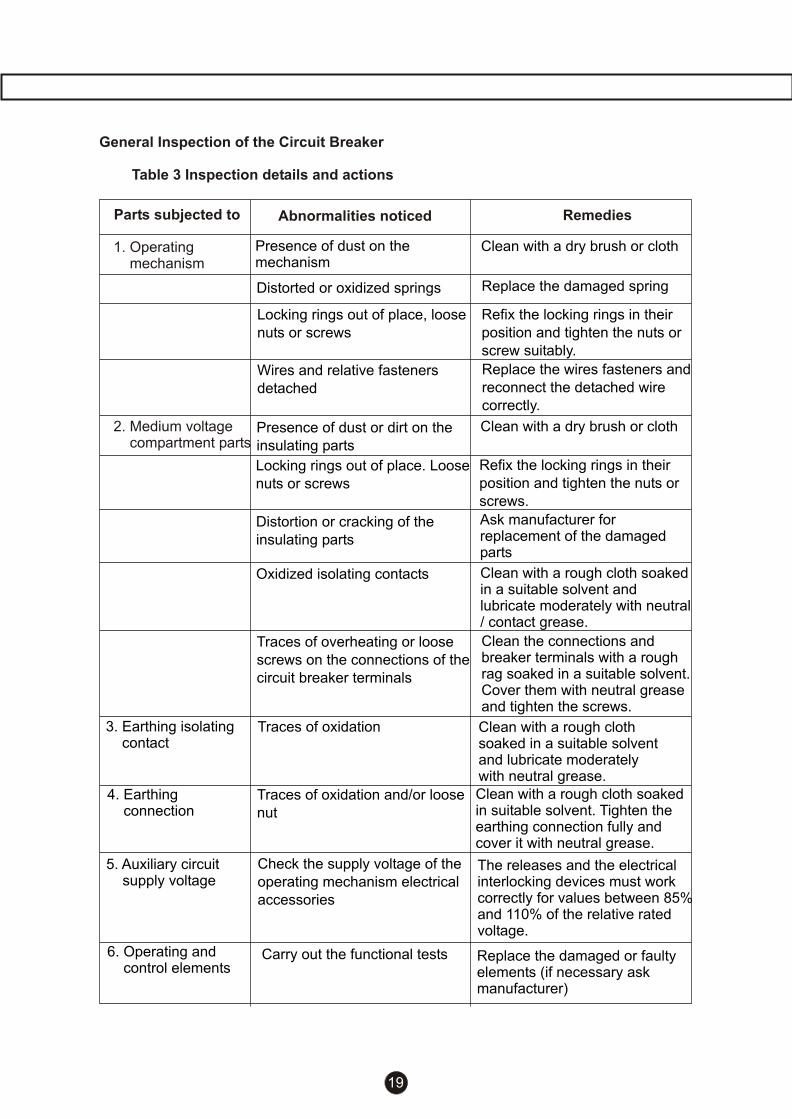
Parts subjected to Abnormalities noticed Remedies
General Inspection of the Circuit Breaker
Table 3 Inspection details and actions
Presence of dust on themechanism
Clean with a dry brush or cloth
2. Medium voltage compartment parts
Distorted or oxidized springs
Locking rings out of place, loose nuts or screws
Wires and relative fasteners detached
Presence of dust or dirt on the insulating parts
Locking rings out of place. Loose nuts or screws
Replace the damaged spring
Refix the locking rings in their position and tighten the nuts or screw suitably.
Replace the wires fasteners and reconnect the detached wire correctly.
Clean with a dry brush or cloth
Refix the locking rings in their position and tighten the nuts or screws.
3. Earthing isolating contact
Distortion or cracking of the insulating parts
Ask manufacturer for replacement of the damaged parts
Oxidized isolating contacts
Traces of overheating or loose screws on the connections of the circuit breaker terminals
Traces of oxidation
Traces of oxidation and/or loose nut
Check the supply voltage of the operating mechanism electrical accessories
Carry out the functional tests
4. Earthing connection
5. Auxiliary circuit supply voltage
6. Operating and control elements
Clean with a rough cloth soaked in a suitable solvent and lubricate moderately with neutral / contact grease.
Clean the connections and breaker terminals with a rough rag soaked in a suitable solvent. Cover them with neutral grease and tighten the screws.
Clean with a rough cloth soaked in a suitable solvent and lubricate moderately with neutral grease.Clean with a rough cloth soaked in suitable solvent. Tighten the earthing connection fully and cover it with neutral grease.
The releases and the electrical interlocking devices must work correctly for values between 85% and 110% of the relative rated voltage.
Replace the damaged or faulty elements (if necessary ask manufacturer)
19
1. Operating mechanism

D. OPERATION & MAINTENANCE
INSPECTIONS:
Operating mechanism 1 X X X General inspection
complete /lubrication
Screw connections 5 X For tightness
Cable connections 5 X For tightness
Return springs X For Deformation
Circlips and Retaining 5 X X For Deformation
rings & Intactness
Interlocking rod assly. X For proper
functioning
Microswitch assly. X For proper
functioning
Motor cut off switch X For proper
functioning
MAINTENANCE:
Lubrication 1 X X X
Closing spring assly. X For Deformation
Spring charging X For proper
motor functioning and
arcing level
Return springs X For Deformation
Stop washer X For Deformation
Auxiliary switch 2 X For gap setting
setting
Flexible X For tightness
Trip coil
Close Coil
Undervoltage coil For proper
Blocking coil functioning
Additional trip coil
Major overhaul
Task/Parts tobe Based On years Based on No. Of As Points to Note
maintained operations reqd.
Occasionally After 5,000 10,000 20,000
Year
1
5
5
5
1
2
X
X
X
X
X
X
X
X
X
X
X
X
X
X
X
X
X
X
X
X
X
X
X
X
X
X
X
X
Table 4 : Inspection periodicity
Lubrication
All the sliding parts subject to friction must
be lubricated at the scheduled time.
The lubrication shall be carried out as per
the schedule given in table 2 , clause no. 6.3.
Clean brush or soft cloth shall be used to
carry out the lubrication. The special
grease type ISOFLEX TOPAS N852 shall be
used for operating mechanism lubrication. The
sliding parts shall be operated a few times
after lubrication so that the lubricant will
penetrate properly through out the sliding /
rolling surface.
20

General
Weight of each pole assembly is approximately
12 Kg for VD4-E and 17 Kg for V D4.
The pole assembly (Drg.4a & 4b,pg. No. 45)
consists of the following components :
Pole housing (V1001 / V2001)
Vacuum interrupter (V1002 / V2002)
Operating stud (V1003 / V2003)
Flexible conductor (V1008)
Roller contact assly. (V2008)
Top connection bar / Support
(V1004 / V2004)
Bottom connection bar/Contact flange assly.
(V1005 / V2006)
Maintenance
The breaker pole with vacuum interrupter
is maintenance free upto reaching the
permissible number of vacuum interrupter
operating cycles.
Checking of the vacuum is only necessary
when there is a good cause to suspect that
force applied externally to a pole tube has
caused damage to the vacuum interrupter
inside.
Before commencing the maintenance work,
ensure that the circuit breaker :
Is disconnected from the high voltage
and auxiliary voltage terminals.
Is in the open position and the closing
spring of the operating mechanism is fully
discharged.
Is fully withdrawn from the cubicle.
Caution
This service work may only be performed
by switchgear manufacturer's servicing
personnel or adequately trained specialist staff.
Operation & Maintenance of Pole
assembly
Replacement of complete pole assembly
Note To order the complete pole assembly for
circuit breaker type VD4E / VD4, the following
details should be furnished :
Rated voltage
Rated normal current
Breaker type & serial number
Order reference number
Dismantling :
Before dismantling the pole, ensure that the
breaker is in 'open' condition and closing
spring is discharged. To fully discharge the
closing spring, refer instruction 13(pg. No. 30).
Remove the special circlip (V6089) and
the pin (V6090) which connects the
operating stud (V1003 / V2003) end to the
lever assembly from the bottom side.
Remove the Hex. socket head screw
(V6091) from the bottom side of the breaker.
Take care to hold the pole assembly
properly while dismantling the screw.
Separate the pole assembly from the
operating mechanism assembly (V1000 /
V2000).
Assembly:
Hold the pole assembly in a proper position
and match the holes on the housing with the
holes on the bottom side of the breaker
frame.
Tighten the Hex. socket head screw (V6091)
and spring washer(V6092) from bottom side.
Tightening torque for these bolts is 45 Nm.
Insert the special tool in the main shaft, and
rotate the main shaft in the opposite
direction. Also pull the lower end of the
operating stud from bottom side and match
the hole of operating stud with the holes on
the pair of levers.
Insert the pin in the operating stud and put
the special circlip on it.
Similarly, couple all the poles one by one to
the mechanism and bring the mechanism to
a completely open position by rotating the
main shaft in reverse direction.
......
.
....
.
.
.
.
.
.
.
.
.
.
.
.
21

Operation and Maintenance of
Operating Mechanism (Drg. 6A to 6E, pg.nos. 47 to 51)
Refer to the assembly drawings 6A to 6E.
The assembly drawing is self explanatory and
shows different assemblies in different sheets.
First of all make the sub-assemblies ready for
the final assembly as given below:
1. Tripping spring assembly (V4100)(Drg. 6E; pg.no. 51)
Take the spring holder (V4101), place the
compression springs (V4103 and V4104) ,
assembled one inside the other, on it place the
spring guide (V4102) on top of the spring.
Check that the springs are in vertical position
and tighten the socket head bolt M6x70 to
clamp the spring in the compressed position.
Apply a light coat of grease on the outer and
inner surface of the springs.
2. Closing spring assembly (V4200)
(Drg. 6C; pg.no. 49)
Take operating disc (V4201) and insert
separating plate (V4202) in the operating
disc as shown in figure 6C. Hold the plate in
a position and tighten it with a hex. socket
head screw (V4203) with spring washer
(V4204).
Now put this assembly of operating disc on the
spring drum (V4205) on the close side of the
drum and check that it rotates on the drum
easily.
Caution : The hex. socket head screw should
be tightened after the complete assembly of
the breaker before charging the spring to its
required precharge value. Now apply a light
layer of grease on the spiral spring surface
and fix the spiral spring (V4206) with one end
of the spring latched in a groove provided on
the drum and cover the open end of the drum
with the sprocket wheel disc (4207). Mount
the roller chain (V4208) and tie it with wire
so that it will not come out from the sprocket
wheel disc.
D. OPERATION & MAINTENANCE
3. Stop washer assembly (V4300) (Drg. 6B; pg.no. 48)
Take curve washers LHS & RHS (V4301[A/B]
/ V4302 [A/B]) and insert 6 nos. dampers
(V4303) in each curve washer. Now insert 6
cylindrical pins (V4304 [A/B]) in the curve
washer LHS with a light coat of grease. Press
the pins completely in the curve washer.
Now insert the stop washer (V4305 [A/B]) in
such a way that stopper nose of curve washer
and stop washer are in opposite direction to
each other and at 45° apart, refer fig. 6B.Once
the stop washer is inserted in the pins, also
press the right hand curve washer in the pins
and press the assembly so that there is no gap
between the three cam discs. After the
assembly, apply a light coat of grease on the
periphery of the cam disc.
4. Latch assembly (V4400) (Drg. 6B, pg.no. 48)
Take the latches (V4401 and V4402)
respectively, mount them on the common pin.
On the other end of the latch, insert link one
each (V4403) and put the circlip (V4404) on
both the latches. Now, hold both the free ends
of the links in the fish plate (V4405) and pass a
cylindrical pin (V4406) and lock it with the
circlip (V4404).
Apply a light coat of grease Isoflex Topas
N852 on the moving area of latch for free
movement of the latches.
5. D-Shaft Assembly (V4500) (Drg. 6B, pg.no. 48)
Take a D-Shaft (V4501 ), as shown in drg. 6B.
Insert the shaft in the crank (V4502) as shown
in fig. 6B. The position of the crank is very
important. Hold the assembly properly and
insert the spring dowel pin O5x30 (V4503)
and fix the crank by a dowel pin. Hammering
to be done very carefully so that it will not
damage the crank.
6. Cam disc Assembly (V4600)(Drg.6E, pg.no. 51)
Hold the cam disc (V4601) firmly on the
working table and press the spring dowel pin
(V4602 and V4603) respectively, one inside
the other.
/
22

Caution
Outer spring dowel pin slit should be pressed
in such a way that the slit is kept towards
the center of the cam and the inner spring
dowel pin slit should be kept opposite to the
outer one.
7. Half shaft assembly (V4700) (Drg. 6B, pg.no. 48)
Take the hex. socket head screw M4x16
(V4701 ) as shown in drg. 68. Hold 2 cranks
(V4702) as shown in the drg. Mount the fish
plate (V4703) on tripping side and fish plate
(V4704) on the closing side of the crank.
Caution
While mounting these fish plates, ensure that
the slots provided on the fish plate are well
guided in the boss provided on the crank
( V4702).
Now insert 1 no. plain washer (V4705)and 1
no. plain thick washer (V4706). Again insert
(V4705) and lock it with nylock nut (V4707).
Similarly for the other crank, put washer
(V4705) and lock it with nylock nut.
Now take that half shaft (V4708). Apply a light
coat of grease on both the ends. Insert a roll
pin(V4709)on the hole provided on the slit end
of the half shaft. The role pin insertion should
be such that it should equally come out of the
half shaft from both the sides. Now insert the
half shaft in the crank (V4702) as shown in
drawing.
Insert the torsion springs (V4711 ) and (V4710)
in each shaft and lock one end of the spring
in between the washer (V4705) and lock the
other end with the half shaft itself.
CHECK :
Holding one of the fish plates, check the free
movement of the other fish plate and half shaft.
After checking for both the half shafts, apply
a light coat of grease on the rolling & moving
areas of fish plate.
8. Counter assembly (V4800) (Drg. 6B, pg.no. 48)
Take a counter assembly - item no.
(V4801 ). Position the arm of the counter
suitably and tighten it with a screw driver.
Now mount this counter on a mounting
angle (V4802) with M3 cheese head
screw (V4803) and spring washer
(V4804).
Now hang the tension spring (V4805) in
the hole provided on the arm and crimp its
end suitably so that it will not come out of
the hole.
9. Supporting crank assembly (V4900)(Drg. 6B, pg.no. 48)
Take the supporting crank ( V4901 [A/B]
and V4902[A/B]) and identify it as LH side
and RH side on the basis of chamfer
provided. The chamfers of both the
supporting cranks should be face to face
to each other and then - fix the locking
roller (V4903 [A/B]) and the cylindrical pin
(V4904) a light coat of grease Isoflex
Topas N852 .
Now put the spacer (V4905[A/B]) in
between the two supporting cranks duly
greased on from inside and then insert a
grooved pin (V4906[A/B]) through the
given hole of the supporting crank as
shown in drg.6B from the RH side. Apply a
light coat of grease on the rolling area of
the supporting crank and the locking roller.
10. Ratchet assembly (V5100) (Drg. 6C, pg.no. 49)
Refer to drg. 6C showing the assembly of
the ratchet for charging.
First of all take a shaft (V5101 ) and place
it in such a way that the groove side of the
shaft is up and then put the items in
sequence as given below :
First take Hex. socket head cap screw
M6x45 & M6x30 (V5102 & V5103) insert
spacer (V5104), longer screw.
23

D. OPERATION & MAINTENANCE
Now in a small hole of the conical plate
(V5107), insert V5105 - M3x25 cheese head
screw M3x25 (V5105) and a tubular rivet
(V5106). Above that insert support plate
(V5108) with cheese head screw (V5109) and
tubular rivet (V5110)fixed on it. After this, insert
the cylindrical pin (V5111 ) and locate the
sprocket (V5112) with the right direction. Apply
a light coat of grease on the pin and in
between the conical plate and support plate.
Now take 2 nos. latch (V5113), hook both
the latches to the spring (V5114) properly and
fix it in the special slots provided on the
support plate and conical plate one each. The
charging lever (V5115) shall be located on two
hex.socket head screws fixed earlier. Repeat
the assembly of support plate and conical
plate duly greased and fix the other end of two
latches in the slots. Put another tubular rivet
(V5110) and lock the small cheese head
screws with a nylock nut (V5116) of size M3.
Do not excessively tighten the nylock nuts.
Also fix the nylock hex. nut (V5117) on hex.
socket head screw M6 on the longer screw put
two plain washers (V5118) and then one big
washer (V5119) and tighten it with t he nylock
nut (V5117).
Check the assembly for its operation by
charging it through the hole provided on the
charging lever (V5115) for its movement
in the right direction. Also check the assembly
for spring action for the latches.
11. Operating lever assembly (V5200) (Drg. 6E, pg.no. 51)
Take the operating levers (V5201 [A/B] &
V5202 [A/B]) and pair it on the basis of LH
side 8 RH side. Locate the tripping spring
assembly as shown in the fig. 6E.
Now take the bolt (V5203) and insert the bolt
through LH side lever and pass it through
the roller bearing (V5204). Put the circlip
(V5205) and clamp it. For R-pole operating
lever special pin(V5206), shall be used instead
of (V5203).
12. Operating mechanism assembly(V5200) (Drg. 6A-6E, pg.no. 47 - 51)
The operating mechanism assembly is
sub-divided into different sub-assemblies :
1 ) Half shaft assembly.
2) D-shaft assembly.
3) Operating lever assembly.
4) Control shaft assembly.
5) Supporting crank assembly.
6) Main shaft assembly.
7) Charging ratchet assembly.
8) Blocking lever assembly.
9) Auxiliary shaft assembly.
10) Coil assembly.
After keeping all sub-assemblies ready for
main assembly, we shall start the main
assembly of operating mechanism. Refer drg.
6A to 6E for the mechanism assembly.
Take operating housing (V6001 ) and fix
the special bush (V6002) as shown
in drg. (6B & 6D). Apply a light coat of
grease and mount the half shaft
assembly as shown in the drg. 6B & 6D
After this assembly, the D Shaft assembly
(V4500) shall be mounted as shown in
drg. 6A & 6B. Place the bush (V6003) in
the hole provided in the side sheet. Insert
the D-shaft assembly with torsion spring
(V6004) and push the bush (V6005) from
outside the sheet and hold it in the proper
position as shown in fig 6B. Once the
positioning is done, clamp the bush with
bracket (V6006), and hold the bracket
with hex. Socket headed screw (V6007)
with spring washer & hexagonal nut
(V6008 & V6009).
After this assembly, the assembly of 3
operating levers (V5200) shall be done.
The assembled levers are to be inserted
in the pivot plates of the operating
housing as shown in the drg. 6E. With the
spacer (V6010) and the duly greased
grooved pin (V6011 ), which is to be
clamped on both the ends by a special
circlip (V6012). Ensure that the spring
guide is well located in the hole provided
12.1
12.2
12.3
24

on the operating housing as well as the
free movement of the lever assembly in
the operating mechanism. Use stepped
bush (V6062) for the assembly of
R-pole operating lever.
Now the assembly of the control shaft
shall be carried out in the following steps.
First of all, fix the bush (V6013) duly
greased from inside - as shown in drg 6D,
in the middle partition of the operating
mechanism. Now insert the control shaft
(V6014) as shown and put torsion spring
(V6015) in the other end of the control
shaft and then fix the bush (V6002)
from outside and locate the control shaft
in it. Apply a light coat of grease inside
the bush, place one or two washers
(V6016), depending on the space
available next to the bush. Now insert
the spiral dowel pin (V6017) in the holes
to locate the control shaft and to hold the
torsion spring in a position. Now insert the
lockout lever (V6018) with the torsion
spring (V6019) inside the lockout lever
as shown in Fig.6B. Position the dowel
pin (V6020) well above the leg of the
torsion spring and press the dowel pin
until it comes out from the other end.
Check:
1) Check the movement of the control
shaft. It shall be free in the two end
bushes.
2) Check the action of the torsion
spring by applying a force on the
lockout lever.
3) Check the dowel pin - item no.
(V6020) is well located in the groove
of the lockout lever and on the leg of
the torsion spring. Also check the
projection of dowel pin from the rear side.
4)Check the other two roll pins (V6017),
are equally out of the control shaft from
both the sides and dowel pins are not
rubbing on the bush (V6013).
As per the sequence of assembly,
supporting crank assembly shall be
mounted on the operating mechanism at
12.4
this stage.
Fix the bush / spacer (V6021/ V6063)
Refer assembly fig. 6B in the hole
provided on operating housing. Apply a
light coat of grease from the inner
surface of the bush / spacer and take
the assembly of supporting crank made,
as explained in point no.9 (V4900).
Remove the grooved pin (V4906 [A/B])
without disturbing the whole assembly
and hold it in the proper position and
insert the same pin through the middle
partition of the operating mechanism
and pass it through the supporting
cranks and bushes (V6064 & V6065)
mounted on the other plate of the
mechanism. Hook the long leg of the
torsion spring (V6015) in the groove
provided on the pin (V4906 [A/B]) with a
special fixing screw driver carefully.
Check : Check for the free movement of
the supporting crank inside the grooved
pin (V4906 [A/B]).
After this assembly, the assembly of
main shaft shall be carried out in the
following sequence.
Refer, (6A,6C & 6D), separate out all the
items to be mounted on the main shaft
and clean them thoroughly, apply a light
coat of grease ISOFLEX TOPAZ N852.
Fix the bush (V6022). Apply a light coat
of grease and insert a main shaft
(V6023) through it. Now, before inserting
the assembly of closing spring (V4200),
Insert the cam disc (V6024), as shown
in drg. 6C. The cam disc crest profile
shall be kept towards the front side or
operator side. Mount the compression
spring (V6029) and the roller (V6030) on
the control shaft (V6014) and hold it with
a clip and now insert the closing spring
as explained in point no. 2, align the
hook of the spiral spring with the shaft
keyway and insert the shaft through the
spring drum and the operating disc,
12.5
12.6
25

which is mounted on the spring drum.
As soon as the roller (V6030) rests on a
operating disc, remove the clip and
release the roller. Push the main shaft
till it comes out of the cam disc (V6024).
The next component on the main shaft
is the cam disc assembly (V4600). Fix
the cam disc assembly as per point 6
and as shown in drg. 6C & 6E. The
dowel pin position with respect to the
key way of cam disc is very important
here. When the cam disc is inserted in
the main shaft, the dowel pin shall be on
the rear side and it shall be well located
in between operating lever assembly
(V5200) of the Y-Pole (middle pole).
After this insertion, the spacer tube
(V6025) and the special washer (V6026)
shall be inserted as shown in fig 6D.
Now, the lever assembly (V6027) shall
be mounted on the shaft and fix the
roller (V6028), duly greased, on the pin
of the lever assembly.
Now take the control washer (V6031),
apply a light coat of grease in the
groove of rolling surface and hold it on
the roller (V6028) and insert the main
shaft through the control washer as
shown in fig. 6D. The next step is to
insert the spacer tube (V6032). This
spacer shall be inserted in such a way
that the longer edge from the cutout is
inserted in the shaft from left hand side.
Then insert the stop (V6033) in the shaft
key way and the cutout of the spacer.
Push the shaft still further till it comes to
the end of the spacer. The next
assembly on the main shaft is the
assembly of stop washer (V4300)
(refer point-3) on the main shaft.
Fix the assembly of stop washer in line
with the main shaft and position it in
such a way that out of two noses of the
stop washer the 1st nose is hold against
The roller of the above assembly, i.e.
supporting crank assembly (V4900). The
second nose of the stop washer shall be
in the clockwise direction while looking
from LH side. Align the assembly with
main shaft and insert the key (V6034)
first on the inner cam disc and push the
shaft ahead. Then, locate the other key
on the outer cam disc and push the main
shaft still ahead. Now as the main shaft
comes out of the position, fix the bush
(V6035). Let the shaft guide properly in
the bush as shown in fig. 6B and insert
the spacer (V6025) and then fix the cam
disc assembly (V4600) as described
Point-3 and one more spacer (V6025)
on the other side of the cam disc. Push
the main shaft still further and fix the
retainer circlip (V6036) with a special
circlip plier. Ensure the circlip is fixed
properly in the groove of the main shaft
as shown in the drg 6E.
After this, push the main shaft still ahead
and repeat the assembly of cam disc
(V4600) in the same way as done earlier
and put the retainer circlip on the right
hand side of the shaft.
CAUTION : Ensure that both the circlips
are fixed properly in the groove of the
shaft.
Once this assembly is completed, check
that all the items on the main shaft are
mounted correctly and nothing is missed
out.
The next step is to roll the cam disc
(V6024), in its proper position and lock it
with the hex. socket head bolt (V6037)
and nylock nut - item no. (V5117). This
completes the assembly of main shaft.
CAUTION
A) As the roller (V6030) is a friction roller,
grease shall not be applied on the
surface of the roller.
B) While inserting the main shaft from
right hand side, ensure that the hole on
the main shaft comes to a right position.
For this purpose, the main shaft shall be
inserted in such a way that longer
distance from the edge of the shaft
enters from right hand side.
D. OPERATION & MAINTENANCE
26

12.7 Assembly of charging ratchet :
The charging ratchet assembly which is
made as per point no. 10, shall be
mounted in the spring drum compartment
of the operating housing.
First of all, fix the bush (V6038) on both
the side plates and mount the indicator
lever assembly (V6039) in the bush, at
the same time, the pin on the lever
assembly shall be inserted in the hole of
the control shaft (V6014) and lock it with
a circlip (V4404). Now insert another
bush (V6040) in the slot of the lever and
insert the ratchet shaft in the bush. The
ratchet shaft shall be mounted with a
sprocket wheel, (V6041 ), with chain
(V4208) on it and also the torsion spring
(V6042). Slide the cylindrical pin (V5111)
in the hole of the charging shaft and
match the sprocket wheel to hold by the
pin and fix the sprocket wheel. Ensure,
the position of the sprocket wheel by
locking it with the special circlip (V6012).
Once this assembly is completed, hold
the non-return plate, (V6043) in a proper
position and insert the duly greased pin
(V6068) in the hole of charging shaft as
shown in drg. 6C and fix the other end
with Hex. bolt (V6044). After this, hook
one end of the torsion spring (V6042)
against this bolt and the other end in
between the washers on the charging
ratchet assembly as shown in drg 6C.
Lockout Lever Assembly
Refer drg. (6B, pg.no. 48).
Take lockout lever (V6045), insert pin
(V6046). Now hold the torsion spring
(V6047) within the lockout lever. Insert
the special pin (V6048) from right hand
side. Put the thick washer (V6049) after
the middle partition and insert the
lockout lever with the spring mounted in
the pin. Now, hook one end of the
torsion spring (V6004) wound on the
D-shaft assembly on a special pin
(V6050) and pull the other end of the
spring on the special pin(V6048) then
12.8
push ahead the pin through the lockout
lever. Now, insert the torsion spring
(V6051) in such a way that one free end
shall be lifting the pin (V4904) of the
supporting crank assembly. Push the pin
further to pass it through the other sheet
and fix the circlip (V6052). Now, pull the
free end of the torsion spring (V6051)
and hook it to the LH side sheet with the
special tool.
Auxiliary Shaft Assembly :
(Drg. 6D& 6B, pg.no. 50 & 48)
The auxiliary shaft assembly is done on
the upper side of the operating
mechanism and is used for operating the
auxiliary switch as well as the ON-OFF
indicator.
This assembly shall be started from right
hand side.
CAUTION: While inserting the auxiliary
shaft (V6066), check the hole position of
the shaft. Fix the bush (V6053) on the
RH side plate of the operating housing
and insert the auxiliary shaft through the
bush. Then insert 2 nos. crank (V6054)
in the opposite direction. Let the shaft
pass through the next plate of the
operating housing and then pass it
through the ON-OFF indicator(V6061 ).
Let the auxiliary shaft to come out from
the next plate and add washer (V6016).
Now, insert the lockout lever (V6055)
duly hooked with the torsion spring
(V6056). Now insert the washer (V6016)
again and insert the crank (V6057). Now,
push the auxiliary shaft, align the latch
assembly as made earlier in point no. 4
in a proper position and insert the
auxiliary shaft through a spacer (V6058).
Now, insert the bush (V6002) on the
plate of operating housing from inside
duly greased and then push the auxiliary
shaft through the bush.
Push the shaft till it matches with the
hole on crank (V6057) and fix the dowel
12.9
27

pin (V6017) through the shaft. Also
hammer the same dowel pin to fix the
ON-OFF indicator (V6061).
Now position the two cranks (V6054) in
the appropriate position and fix it with
hexagonal socket head bolt (M4x25)
(V6059) with the nylock nut (V4707).
CHECK
Check that the whole assembly of the
auxiliary shaft is correct as per drawing
and no part is missing in it.
Now connect the other end of the lever
assembly (V6027) to the ON-OFF
indicator with a pin (V6060) and a
special clip (V6076).
Auxiliary Switch Assembly
(Drg.7; pg.no. 52)
Totally there are three auxiliary switches
used in this circuit breaker. Out of the
three auxiliary switches, one is used as a
motor cut-off switch and other two are
used for closing & tripping circuit and for
annunciation.
Take item no. (V4207) - auxiliary switch
plate and on the top side of the plate, fix
two spacers (V6070) with the help of
M5x25 hexagonal socket head screw
(V6071) and self locking nut (V6072).
Do not forget to fix the earthing strip
(V6073) and fix the special pin (V6074).
Note-1 : The auxiliary switch used for
motor cut-off have a contact combination
of 2N0+3NC.
Note-2 : The other two switches have a
combination of 2NO+3NC and 3N0+2NC.
Thus, the total number of contacts are
5NO+5NC.
First of all, insert the cylindrical pin - item
no. V6075) in the fork of the auxiliary
switch and lock it with the circlip - item
no. (V6077).
12.10
Now place the rubber washer - item no.
(V6078) on the tapped holes of the
auxiliary switch plate. Then place the
auxiliary switches (V6079 & V6080) as
identified earlier and tighten it with the
hardware - item no. (V6081, V6082 &
V6083) hex. Socket head screw M4x30,
M4 spring washer and M4 plain washer
respectively. This hardware shall be
kept loose and shall be tightened after
the setting of the auxiliary switch.
CAUTION :While inserting the auxiliary
switch plate, ensure that the fork of the
auxiliary switch is properly guided in
the operating crank of the auxiliary
shaft and there is no undue stresses on
the auxiliary switch fork otherwise it
may break.
CHECKING : Once the fixing is done,
the auxiliary switches, which are
mounted loosely, shall be fixed after
setting of the stroke.
Setting-1 : For motor cut-off switch :
Charge the spring of the circuit breaker,
as it charges the bracket lifts (V6088)
up the auxiliary switch fork. You should
measure the gap between moving fork
and the fixed body of the auxiliary. The
gap shall be set at 1.0 to 1.5 mm. After
this, fasten the screws of the auxiliary
switch.
Setting-2 : Switches for annunciation
scheme.
This setting shall be done when the
breaker is in closed condition.
Close the breaker and set the gap
between the forks of the auxiliary
switches and the body to 1 to 2 mm
approx. and fasten the screws
completely.
12.10.A - Auxiliary Switch Assembly
(Drg. 7A, pg.no.53)
The new arrangement of Auxiliary Switch
is recently introduced in these breakers
D. OPERATION & MAINTENANCE
28

Operating Coil Assembly
(Drg 8; pg.no. 54):
Normally the two coils are mounted on
each circuit breaker to facilitate the
Electrical closing and electrical tripping of
the circuit breaker. Vacuum circuit breaker
type VD4E & VD4 is mounted with a
special type of coil in which electrical
energy is converted into a rotary motion
to operate the closing and tripping
mechanism of the circuit breaker. Refer
drg.8 which shows general arrangement
of mounting of the operating coils.
12.11
and the constructional details are shown
in the drg: 7A. This arrangement is simple
in construction and it consists of one
auxiliary switch containing 6N0+6NC
contact configuration having a rotary
action and rotates 90° between two end
positions.
The auxiliary switch (V6122) is mounted
in a inverted position on the top sheet of
the breaker frame and the movement to
operate the auxiliary switch is taken from
the main shaft instead of an auxiliary
shaft as in earlier version. A simple
Aluminium link (V6124) is connected to
transfer the motion from shaft to the
auxiliary switch shaft through an arm
(V6123).
Dismantling of Auxiliary switch:
Remove the M6 bolt from top of the
breaker frame and remove the pin
connecting the Aluminium link with the
operating lever.
Assembly of the Auxiliary switch:
Mount the auxiliary switch in the inverted
position on the breaker frame and fix it
with the M6 hardware. Now position the
arm of the auxiliary switch in the
respected position and fix the aluminium
link to connect it to the operating lever of
the breaker, push the pin in the link and fix
the split pin. Ensure the bending of the
split pin is proper.
There are different coils available for
different voltage ratings and one should
ensure while ordering/mounting of coils
on the circuit breaker for the for the
right coils as per specifications.
Once the appropriate coils (as per
specified voltages in the order) are
identified, they are fixed in the proper
position and shall be located in the
holes provided on the fixing plate.
Now, hold the magnet support (V6086)
such a way that it backs-up the coils.
Insert the hexagonal socket head screw
M4x35 (V6087) along with the plain &
spring washers (V6083 & V6082). The
fixing plate is provided with a tapped
holes to mount these screws.
CAUTION
While fixing the closing coil (V6084) &
tripping coil (V6085), check the
following:
a) Direction of rotation of coil.
b) Roll pin on the plunger shaft is
guided properly in the half shaft
slits.
CHECK
Once both the coils are mounted on the
breaker, check the movement of the
push button levers is smooth and proper.
After this, take the wires of the coil out
and connect it to the appropriate
auxiliary switch position or on the
terminals as per order related
schematics or typical circuit diagram
refer. drg. 5
12.11.A - Operating magnet assembly
(Drg. 7A, pg.no. 53 )
The new operating coil assembly
consists of two different operating coils
mounted independently and operate the
closing & tripping latches
independently. The axial movement
of plunger of the coil is converted
to the rotary movement of the latching
29

D. OPERATION & MAINTENANCE
12.12
mechanism. The collar of motor should be
properly located in the hole provided on the
motor support plate.
Now tighten the hexagonal socket head
screw M6x16 (V6093) along with spring
washer (V6094). The crank (V6095)
along with cover plate and cylindrical pin.
(V6097) are assembled with the help of
dowel pin (V6098) as shown in drg.9.
One end of cover plate is connected to the
charging ratchet assly. with help of Grooved
pin(V6099) and circlip (V6100).
Then Fix the crank with motor shaft by using
Hex socket head cap screw M4x35 (V6101 )
washer (V6083) and self locking nut (V4707).
12.13.A Motor cutoff Switch
Assembly :
The motor cut-off switch assembly is now an
independent assembly where the bracket
(V6088) drives the Lever assembly (V6129)
and operate a set of snap-action switch
(V6130) by a lever-fulcrum mechanism.
Drg7A shows the arrangement of motor cut-off
switch and its function. There are normally 3
switches mounted on the micro switch
mounting bracket (V6131) consisting of
1 NO + 2 NC contacts used for Motor cut-off
spring charge indication and closing interlock
purpose.
12.13
13. Instruction for discharging and charging:
Before starting any maintenance work or
replacement of components of operating
mechanism. One shall ensure that the closing
spring is in completely discharged condition.
Without discharging the closing spring to its
zero energy level it is very dangerous to work
on mechanism. Follow the steps given below
to discharge the spring.
1) The spring is normally charged for 4 turns.
2) Charge the spring manually and carry out
ON-OFF operation.
3) Using the screw driver press the roller
(V6030) against the compression spring
(V6029) which is mounted on the lever
assembly (V6014), the roller will drop down
shafts, thus executing the closing and
opening command.
Dismantling of magnets: Remove the
M6 bolt from top of the breaker frame and
remove the closing coil (V6125) / opening
coil (V6126) from the breaker as shown in
the Fig No 7A.
Assembly of magnets: Ensure the rating
of the closing magnet l opening magnet is
as specified in the drawing. Mount the
closing magnet / opening magnet
mounting bracket in the inverted position
on the breaker frame and fix it with the M6
hardware. Now set the setting screw
provided on the closing f lap (V6127) and
opening flap (V6128) which is connected
to the half shaft and lock the same with
nut. Ensure the bending of the split pin of
the plunger is proper.
Coupling of drive and pole :
Coupling of drive and poles is possible
only when the operating mechanism and
poles are assembled completely.
Once the drive assembly is completed,
discharge the tripping springs, which are
precharged for assembly easiness. The
discharging shall be done by removing
the hexagonal socket head bolt from the
rear side by unscrewing it. As you unscrew
these three bolts, the opening springs
get discharged and spring holder cap
seats in a hole provided on the operating
housing. For coupling the poles with the
operating mechanism refer the
assembly instruction as described in
clause A of the pole assembly.
Motor Assembly : (Drg. 9; pg.no.55)
There are different motors available for
different voltage ratings. One should be
very careful while ordering / mounting
motor on the circuit breaker for the
specified voltage as per the order
specification. Once the appropriate motor
is identified, fix the motor properly on the
motor support plate of the operating
30

and then carry out the ON -OFF operation.
4) Repeat the same three times.
5) Last one or two operations may not
complete on its own as the energy level in the
spring gets reduced.
6) Using a special tool rotate the shaft after
each ON -OFF command to complete the
operation.
7) Check the freeness of the spring drum, thus
the spring is completely discharged.
14. Instruction for discharging and charging:
Follow the procedure to charge the closing
spring.
1) Normally 4 complete turns are stored in a
closing spring and a last turn to operate the
breaker.
2) Press the lever assembly(V6039) and hold
it while charging.
3) Mark a line on the spring drum and start
charging manually.
4) Complete 4 rotations of the spring drum and
release the lever assembly.
5) For the next charging the roller (V6030) will
drop in the pocket and spring charging
indicator will show the position
"SPRING CHARGED" .
Now the circuit breaker is ready for operation.
15. Truck assembly (ref. Drg.no. 10; pg.no. 56)
Place the frame assly.(V6102) on the working
table and insert the breaker with pole inside
the frame. Put the spacer (V6103) in between
frame and breaker and tighten hex bolt M12
x45 (V6104). Mount 24 plug assly. (V6105)
on truck frame and interlocking assly (V6106)
as shown in drg 10. Complete the Emergency
trip assly (V6107). Adjust the length of
actuators. Confirm operation of emergency
trip and interlocking rod assembly. Mount
the barrier plate (V6108) from the rear side of
the breaker frame and fix the connection
pieces (V6109) on each terminal and the
connection bars item no (V6110 to V6115)
on each phase upper and lower terminals and
maintain the center distance of 185 +/- 1 . Also
measure the distance between upper and
lower terminal and it shall be 367 +/- 2. Check
the parallelity of the connection bars and
other dimensions as per assembly drg. 10.
Once again check the breaker for
completeness and also paint seal the key
assemblies like interlocks, Auxiliary switches,
Motor assembly, Push rod assembly. Ensure
that greasing is done properly on all the rolling
surfaces and then fix the front cover assembly
(V6116) by hanging it on the top and fix it with
the hex. socket head bolt with the washer.
VD4 / VD4E Breaker for Unisafe Panel:
The switchgear panel type Unisafe and the
vacuum circuit breaker type VD4 / VD4E are
of a very compact design. The main features
of this combination are:
The Rack-in mechanism is made as a
part of the circuit breaker. Hence, the
problems related to interchangeability
are eliminated.
The contact arrangement adapted for
this breaker is Tulip contact system
and hence better alignment, flexibility
and contact engagement with cubicle
contact can be achieved.
The panel contacts are mounted in
the bushing and the metallic shutters
are provided hence, better
compartmentalization is achieved.
Drg 1A shows General Arrangement and
basic dimensions of the breaker type
VD4 / VD4E suitable for Unisafe panel.
.
.
.
31

32

E. LIST OF DRAWINGS & COMPONENT PART Nos.
List of Drawings
Component Part Numbers
E. LIST OF DRAWING & COMPONENT PART NUMBERS Pg.No.
33
34
35

Fig No. Description
1 VD4 / VD4-E Circuit Breaker Drawing
1A VD4 / VD4-E Breakers for Unisafe Cubicle
2 Cross Sectional View Of VD4 Circuit Breaker
3 Cross Sectional View Of VD Interrupter
4A Pole Assembly Of VD4-E Breaker
4B Pole Assembly Of VD4 Breaker
5 Typical Circuit Diagram
6A to 6E Operating Mechanism
7 Auxiliary Switch Assembly
7A Coil & Aux. Switch Arrangement (New)
8 Operating Coil Assembly
9 Motor Mounting Assembly
10 Truck Assembly
List of Drawings
E. LIST OF DRAWINGS & COMPONENT PART Nos.
34

NAME OF ITEM REFERENCE No. DRG. No.
POLE HOUSING
VACUUM BOTTLE ASSY.
GROUP VG2S
OPERATING STUD
CONN. BAR (TOP)
CONN.BAR(BOTTOM)
BUSH
LABEL STICKER
FLEXIBLE CONDUCTOR
SUPPORTING PLATE
SUPPORTING PLATE
CONTACT TERMINAL
SPECIAL NUT
CONTACT NUT
SPRING WAVE WASHER
SAFETY WASHER
HEX. SOCKET HD. CAP SCREW
HEX. SOCKET HD. CAP SCREW
CONICAL SP. WASHER
HEX. NUT
HEX. SOCKET HD. CAP SCREW
POLE HOUSING
VACUUM BOTTLE ASSY.
GROUP VC2
OPERATING STUD
CONNECTION PART
CHAMBER SUPPORT
CONTACT FLANGE
CONTACT PISTON
ROLLER CONTACT COMP.
SAFETY WASHER
CONICAL SP. WASHER
SPRING WASHER
SPECIAL WASHER
SPRING WASHER
PRESSURE PLATE
HEX. SOCKET HD. CAP SCREW
HEX. SC. HD. CAP SCREW
HEX. SC. HD. CAP SCREW
V1001
V1002
V1003
V1004
V1005
V1006
V1007
V 1008
V1009
V1010
V1011
V1012
V1013
V1014
V1015
V1016
V1017
V1018 (Unplated)
V1019
V 1020
V2001
V2002
V2003
V2004
V2005
V2006
V2007
V2008
V2009
V2010
V2011
V2012
V2013
V2014
V2015
V2016
V2017
4A
4A
4A
4A
4A
4A
4A
4A
4A
4A
4A
4A
4A
4A
4A
4A
4A
4A
4A
4A
4B
4B
4B
4B
48
4B
4B
4B
4B
4B
4B
4B
4B
4B
4B
4B
4B
35

NAME OF ITEM REFERENCE No. DRG. No.
HEX. SC. HD. CAP SCREW
CONICAL SP. WASHER
HEX. NUT
GREASE
SPRING HOLDER
SPRING GUIDE
COMPRESSION SPRING
COMPRESSION SPRING
OPERATING DISC
SEPARATING PLATE
HEX. SOCKET HD. CAP SCREW
SPRING WASHER
SPRING DRUM
SPRING
SPROCKET WHEEL DISC
ROLLER CHAIN
CURVE WASHER
CURVE WASHER
DAMPER
CYLINDRICAL PIN
STOP WASHER
LATCH ASSY.
LATCH
LINK
CIRCLES
FISH PLATE
CYLINDRICAL PIN
D-SHAFT
CRANK
SPRING DOWEL PIN
CAM DISC
SPRING PIN
SPRING PIN
HEX. SOCKET HD. CAP SCREW
CRANK
FISHPLATE-OFF
FISHPLATE-ON
PLAIN WASHER
SPRING WASHER
NYLOCK HEX. NUT
HALFSHAFT
V2018
V2019
V2020
ISOFLEX TOPAS N852.
V4101
V4102
V4103
V4104
V4201
V4202
V4203
V4204
V4205
V4206
V4207
V4208
V4301A/B
V43O2A/B
V4303A
V4304A/B
V43O5A/B
V4401
V4402
V4403
V4404
V4405
V4406
V4501
V4502
V4503
V4601
V4602
V4603
V4701
V4702
V4703
V4704
V4705
V4706
V4707
V4708
4B
4B
4B
4B
6A
6A,6E
6E
6E
6A,6C
6C
6A,6C
6C
6C
6A
6A,6C,7
6C
6A,6B
6A,6B
6B
6B
6A,6B
6A,6B
6B
6A,6B
6A
6A,6B
6A
6B
6A,6B
6B
6A,6E
6E
6E
6A,6B
6A,6B
6A
6A,6B
6A,6B
6A,6B
6A,6B,6D,9
6A,6B
E. LIST OF DRAWINGS & COMPONENT PART Nos.
36

NAME OF ITEM REFERENCE No. DRG. No.
SPRING PIN
TORSION SPRING
TORSION SPRING
COUNTER
ANGLE
SLOTTED CHEESE HD. SCREW
SPRING WASHER
TENSION SPRING
BLOCKING CRANK
BLOCKING CRANK
BLOCKING ROLLER
CYLINDRICAL PIN
SPACER
GROOVED PIN
SHAFT
HEX. SOCKET HEAD SCREW
HEX. SOCKET HEAD SCREW
SPACER
SLOTTED CH. HEAD SCREW
TUBULAR RIVET
CONICAL PLATE
SUPPORT PLATE
SLOTTED CH. HEAD SCREW
TUBULAR RIVET
CYLINDRICAL PIN
SPROCKET
LATCH
TORSION SPRING
CHARGING LEVER
NYLOCK HEX. NUT
NYLOCK HEX. NUT
SPRING WASHER
PLAIN WASHER
LEVER
LEVER
BOLT
ROLLER BEARING
RETAINING CIRCLIP
SPECIAL PIN
HOUSING
BUSH
AUXILIARY SWITCH PLATE
TORSION SPRING
V4709
V4710
V4711
V4801
V4802
V4803
V4804
V4805
V4901A/B
V4902A/B
V4903A/B
V4904
V4905A/B
V4906A/B
V5101
V5102
V5103
V5104
V5105
V5106
V5107
V5108
V5109
V5110
V5111
V5112
V5113
V5114
V5115
V5116
V5117
V5118
V5119
V5201
V5202
V5203
V5204
V5205
V5206
V6001
V6002
V6003
V6004
6A,6B
6A
6A
6A,6B
6A,6B
6A,6B
6A,6B,6C
6A,6B
6A
6A,6B
6A,6B,6C
6B
6A,6B
6B,6C
6C
6A,6C
6C
6C
6A,6C
6A,6C
6A,6C
6A,6C
6C
6C
6A,6C
6A,6C
6A,6C
6C
6A,6C
6C
6A,6C
6A,6C
6A
6A,6B,6E
6A,6B,6E
6A
6E
6A,6E
6B,6E
6A
6A,6B,6D
7
6A,6B
37

NAME OF ITEM REFERENCE No. DRG. No.
BUSH
BRACKET
HEX. SOCKET HEADED CAP SCREW
HEX.NUT
SPRING WASHER
TUBE
CYLINDRICAL PIN
RETAINING WASHER
BUSH
LEVER ASSEMBLY
TORSION SPRING
WASHER
SPRING PIN
LOCKOUTLEVER
TORSION SPRING
SPRING PIN
BUSH
BUSH
SHAFT
CAM DISC
SPACER
SPECIAL WASHER
LEVER ASSEMBLY
ROLLER
COMPRESSION SPRING
ROLLER
CONTROL WASHER
SPACER TUBE
STOP
FORK LOCK (KEY)
BUSH
CIRCLIP
MOTOR
BUSHING
LEVER ASSEMBLY
BUSH
SPROCKET WHEEL
TORSION SPRING
NON RETURN PLATE
HEX. BOLT
LOCKOUTLEVER
PIN
SPRING
V6005
V6006
V6007
V6008
V6009
V6010
V6011
V6012
V6013
V6014
V6015
V6016
V6017
V6018
V6019
V6020
V6021
V6022
V6023
V6024
V6025
V6026
V6027
V6028
V6029
V6030
V6031
V6032
V6033
V6034
V6035
V6036
V6037
V6038
V6039
V6040
V6041
V6042
V6043
V6044
V6045
V6046
V6047
6B
6B
6B
6A,6B,6C
6C
6A,6E
6A,6E
6E
6D
6A,6C,6D
6D
6A,6B
6B,6D
6A,6B
6A,6B
6A,6B
6A,6B
6A,6C
6A,6E
6A,6C
6A,6D,6E
6D
6D
6D
6C
6C
6D
6A,6B
6B
6A,6B
6A,6B
6E
6A,6C
6C
6A,6C
6C
6C
6A,6C
6A,6C
6A,6B,6C
6B
6B
6A,6B
E. LIST OF DRAWINGS & COMPONENT PART Nos.
38

NAME OF ITEM REFERENCE No. DRG. No.
SPECIAL PIN
PLAIN WASHER
PIN
TORSION SPRING
RETAINING CIRCLIP
BUSH
CRANK
LOCKOUTLEVER ASSEMBLY
TORSION SPRING
CRANK
SPACER
HEX. SO.HEADED SCREW
CYLINDRICAL PIN
ON- OFF INDICATOR
SOCKET HD.CAP SCREW
PIN
SPACER
HEX.SOCKET HEADED SCREW
SELF LOCKING NUT
EARTHING STRIP
SPECIAL PIN
CYLINDRICAL PIN
RETAINING CIRCLIP
RETAINING CIRCLIP
RUBBER WASHER
AUXILIARY SWITCH
AUXILIARY SWITCH
HEX.SOCKET HEADED SCREW
SPRING WASHER
PLAIN WASHER
CLOSING COIL
TRIPPING COIL
MAGNET SUPPORT
HEX.SOCKET HEADED SCREW
BRACKET
SPECIAL CIRCLIP
PIN
HEX. SOCKET HD SCREW
SPRING WASHER
CRANK
COVER PLATE
CYLINDRICAL PIN
DOWEL PIN
V6048
V6049
V6050
V6051
V6052
V6053
V6054
V6055
V6056
V6057
V6058
V6059
V6060
V6061
V6066
V6068
V6070
V6071
V6072
V6073
V6074
V6075
V6076
V6077
V6078
V6079
V6080
V6081
V6082
V6083
V6084
V6085
V6086
V6087
V6088
V6089
V6090
V6093
V6094
V6095
V6096
V6097
V6098
6A,6B
6B
6B
6A,6B
6A,6B,6C
6D
6D
6A
6B,6D
6A,6B
6B
6D
6D
6A,6D
6A,6D
6A,6D
7
7
7
7
7
7
6D,7
7
7
7
7
7
7,8
7,8,9
8
8
8
8
7
7
7
9
9
9
9
9
9
39

NAME OF ITEM REFERENCE No. DRG. No.
GROOVED PIN
RETAINING CIRCLIP
HEX.SOCKET HEAD SCREW
FRAME
SPACER
HEX.BOLT
24 PIN PLUG ASSEMBLY
INTERLOCKING ASSEMBLY
EMERGENCY TRIP ASSEMBLY
BARRIER PLATE
CONNECTION PIECE
CONNECTION BAR
CONNECTION BAR
CONNECTION BAR
CONNECTION BAR
CONNECTION BAR
CONNECTION BAR
FRONT COVER ASSEMBLY
HEX. BOLT
HALFSHAFT
DOWEL PIN
LOCKING LEVER
BLOCKING LEVER
AUXILIARY SWITCH
AUXILIARY SWITCH ARM
ALUMINIUM LINK
CLOSING MAGNET (NEW)
OPENING MAGNET (NEW)
CLOSING FLAP
OPENING FLAP
LEVER ASSEMBLY
SET OF MICROSWITCH
M/S MTG BRACKET
V6099
V6100
V6101
V6102
V6103
V6104
V6105
V6106
V6107
V6108
V6109
V6110
V6111
V6112
V6113
V6114
V6115
V6116
V6117
V6118
V6119
V6120
V6121
V6122
V6123
V6124
V6125
V6126
V6127
V6128
V6129
V6130
V6131
9
9
9
9
9
10
10
10
10
10
10
10
10
10
10
10
10
10
6A
6A,6C
6B
6B
6C
7A
7A
7A
7A
7A
7A
7A
7A
7A
7A
E. LIST OF DRAWINGS & COMPONENT PART Nos.
40

VD
4E
Bre
ake
r
VD
4 B
rea
ke
r
Drg
. N
o. 1
41

VD
4E
Bre
ake
rfo
r U
NIS
AF
E
cu
bic
le
VD
4 B
rea
ke
rfo
r U
NIS
AF
Ecu
bic
le
Drg
. N
o. 1
A
42

Cro
ss s
ectio
na
l vie
w o
f V
D4
CB
C
ross
sectio
na
l vie
w o
f V
D4
E C
B
Drg
. N
o. 2
1 B
rea
ker
me
cha
nis
m h
ou
sin
g1
.1 F
ron
t co
ve
r -
rem
ova
ble
12
In
su
latin
g m
ate
ria
l po
le tu
be
13
U
pp
er
bre
ake
r te
rmin
al
14
L
ow
er
bre
ake
r te
rmin
al
15
V
acu
um
inte
rru
pte
r1
6.2
Ro
ller
con
tact
/ F
lexib
le c
on
du
cto
r1
7 C
on
tact
pre
ssu
re s
prin
g1
8 In
su
late
d c
ou
plin
g r
od
19
O
pe
ratin
g s
prin
g2
0 S
hift
leve
r pa
ir
43

Drg. No.3
15.1 Insulator15.2 Fixed contact15.3 Movable contact15.4 Metal bellows15.5 Screen15.6 Guide cylinder15.7 Lid
Cross section of vacuum interrupter
44

Drg
. N
o. 4
A P
ole
ass
em
bly
Drg
. N
o. 4
B
Po
le a
sse
mb
ly fo
r V
D4
E / V
D4
bre
ake
r
45

Drg. No.5
Typical circuit diagram
1. Spring charging motor2. Closing coil3. Tripping coil4. (S3, S4) CB Auxiliary switch contacts5. Microswitch operates in T or S positionm6. Plug & socket7. (S1) Motor cut-off switch8. Breaker
46

47
Drg
. N
o. 6
A O
pe
ratin
g M
ech
an
ism
Asse
mb
ly fo
r V
D4
E / V
D4
bre
ake
r

48
Drg
. N
o. 6
B O
pe
ratin
g M
ech
an
ism
Ass
em
bly
fo
r V
D4
E / V
D4
bre
ake
r

49
Drg
. N
o. 6
C O
pe
ratin
g M
ech
an
ism
Asse
mb
ly fo
r V
D4
E / V
D4
bre
ake
r

50
Op
era
ting
Me
cha
nis
m A
sse
mb
ly
fo
r V
D4
E / V
D4
bre
ake
r
D
rg. N
o. 6
D

51
Op
era
ting
Me
cha
nis
m A
sse
mb
ly
fo
r V
D4
E / V
D4
bre
ake
r
D
rg. N
o. 6
E

52
Auxiliary Switch assembly
Drg. No. 7

53
Arrangement drawing withcoil and auxiliary switch
Drg. No. 7

54
Op
en
ing
co
il a
sse
mb
ly
D
rg. N
o. 8
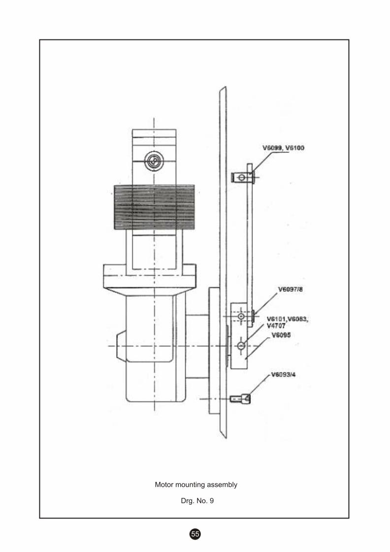
55
Motor mounting assembly
Drg. No. 9
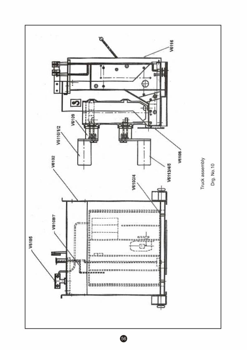
56
Tru
ck a
sse
mb
ly
D
rg. N
o.1
0

ABB LimitedPlot No. 79, Street No. 17MIDC Estate, Satpur,Nashik - 422 007
Tel: +91 235 2351095 to 8 +91 253 2351261 to 4Fax: +91 253 2350644 / 2351249
No liability is accepted for the accuracy of the information contained in the publication. We reserve the right to makeamendments in the course of technical progress.
1VDU09001-YN


