PC 5200 Quick operating and installation guide Notice d'utilisation et de montage Kurzbedienungs- und Einbauanleitung Korte gebruiksaanwijzing en montage-instructies Istruzioni per il montaggio e brevi istruzioni per l'uso Instrucciones breves de uso y de montaje Kortbeskrivning och monteringsanvisning Kort betjenings- og monteringsvejledning Pikaopas ja asennusohjeet www.vdodayton.com
Transcript
PC 5200
Quick operating and installation guideNotice d'utilisation et de montage
Kurzbedienungs- und EinbauanleitungKorte gebruiksaanwijzing en montage-instructies
Istruzioni per il montaggio e brevi istruzioni per l'usoInstrucciones breves de uso y de montajeKortbeskrivning och monteringsanvisningKort betjenings- og monteringsvejledning
Notes on operatinginstructionsThese operating instructions include only afraction of the functions available in yourmultimedia system. You can find the com-plete version in Adobe PDF format on thesupplied DVD-ROM. We recommend thatyou read the complete version in order tomake use of the many options the systemoffers.The following reading aids are used to sim-plify these operating instructions:
☞ asks you to perform an action.
✔ shows the unit’s reaction.
✎ provides extra info.❑ identifies a list.
A Safety instructions and warnings containimportant information for safe use of theunit. Failure to observe this information mayresult in material damage or personal injury.Therefore, please observe this informationwith particular care.
Subject to technical and visualchanges and typing errors.
For your safety!A The use of the navigation system by nomeans relieves the driver of his/her responsi-bilities. Always observe the applicable trafficregulations and take the current traffic con-ditions into consideration. You always havepriority over the information provided bythe navigation system if the actual traffic sit-uation and the information from the naviga-tion system conflict.
A For the sake of traffic safety, performinputs to the navigation system only priorto the trip or when the vehicle is stationary.
A Only look at the monitor if it is safe to doso. Find a suitable place to stop should youneed to look at the screen for a longer periodof time.
A The system does not take the relativesafety of the suggested routes into consider-ation. Road blocks, building sites, height orweight restrictions, traffic or weather condi-tions or other influences which affect theroute safety or travel time are not taken intoconsideration for the suggested routes. Useyour own discretion in order to decide onthe suitability of the suggested routes. Usethe “Alternative Route” function to receivebetter routing suggestions, or simply followyour preferred route and the automaticrouting recalculation will plan the route forthe remainder of your journey.
A In certain areas one-way streets, turn-offand entry restrictions (e.g. to pedestrian zones)have not been surveyed. In areas such asthese the navigation system will issue awarning. Pay particular attention to one-waystreets, turn-off and entry restrictions.
A The values displayed on the system’s“Trip computer” giving the current speed,driving time and the elapsed distance arecalculated values. Accuracy cannot always beguaranteed. In the case of speed, the vehiclespeedometer must always be given priority.
A The current legal road traffic speed limitalways takes priority over the values storedon the navigation SD card. It is impossible toprovide an assurance that the speed valuesof the navigation system will always matchthose of the current traffic regulations inevery situation.
A Do not rely exclusively on the navigationsystem when attempting to locate an emer-gency service (police, fire service, etc.). It can-not be guaranteed that all available emer-gency services in your vicinity are stored inthe database. Use your own discretion andabilities to secure help in such situations.
A Please make certain that all persons usingyour multimedia system have access to thismanual, and that they read the instructionsand suggestions concerning system opera-tion prior to use.
OPERATION SETUP INSTALLATIONCONTENTS
6
Range of functions of yournavigation system■ Range of functionsSome of the functions described in this manualare only to be used in conjunction with op-tional accessories. It may also be that usecannot be made of certain functions in somecountries because the data has not been sur-veyed. Due to the large range of functions, aconscious decision was taken not to allow allthe settings to be used in any combination inthe interests of ensuring ease of use andfunctionality.
■ Operating restrictions(country-specific)
If a symbol depicting a crossed-out hand ap-pears in the bottom status line it means thatonly limited operating options are availablewhilst driving. Whether or not this functionis activated will depend upon the prevailingnational regulations.
Inserting/changing SD cards■ Inserting the card
☞ Insert the card into the SD card slot withthe label facing up and the slanted corneron the right.
☞ Press the card into the slot until it en-gages.
■ Removing the card
☞ Carefully press the centre of the card.
✔ The SD card is released.
☞ Pull the card straight back to remove itfrom the SD card slot.
■ Information on SD memory cardsOnly insert SD memory cards in the SD cardslots. Inserting other card types can result inmalfunction or destruction of the unit andthe card.Only use SD memory cards from well-knownmanufacturers. The use of other cards mayresult in malfunctions.Do not use miniSD™ cards with adapters. TheminiSD™ card could become detached fromthe adapter when removing it from the cardslot. The adapter could then get stuck in thedevice.
SD is a registered trademark of the ToshibaCorporation.The SD logo is a registered trademark.
Remote controlsDepending on the scope of supply, variousremote controls might be used. Full func-tionality can only be ensured if the correctremote control is activated.
■ Activating the correct remote control
☞ Select “Settings –> Remote control” andactivate the desired remote control bypressing the OK button.
☞ If you additionally use a steering wheelremote control, activate this with a tick.
A Please do not expose the remote controlwith inserted batteries to direct sunlight.
■ Active holder (accessory)If you only use your remote control in istactive holder, we recommend that you removethe batteries from the remote control. Thesystem can be operated when the remotecontrol is in its holder.
■ Battery change displayIf the system no longer responds when thebuttons are pressed or the battery symbol(appears in the status line, the batteries ofthe remote control must be changed.
OPERATION SETUP INSTALLATIONCONTENTS
7
Notes:In many countries, flat batteries may not bedisposed of together with the normal domesticrubbish. Please determine how to dispose offlat batteries in accordance with local regula-tions.Use only leak-proof batteries. Battery leakagecan cause damage to the remote control orto your vehicle.Never expose the remote control to directsunlight or extreme heat. The batteries dis-charge at high temperatures and there is arisk of leakage.
■ RC 5400
1 VOICE/ALT-R: Press briefly: Calls up thecurrent audible guidance message.Press and hold: Switches to “AlternativeRoute” menu.
2 4, 6,8,2: Cursor buttons, move thecursor in the menus.
3 OK: Confirms a selection.
4 ESC: Press briefly: Jumps back to theprevious menu.Press and hold: Jumps directly to theStart menu.
5 NAVIGATION: Press briefly: Switches thedisplay type of the guidance screen.Press and hold: Moves directly to theStart menu.
6 ENTERTAIN: Press briefly: Calls up thepreviously used entertainment source.
7 FAVOURITE: This button is freely pro-grammable to provide direct access toselected functions. Detailed informationon programming this button can befound in the “Settings” section of thePDF version of the operating instructions.
8 W, V: Volume setting.
9 HOME: Press briefly: Adopts the addressstored under “Home” for directionalguidance.Press and hold: Adopts the addressstored under “Work” for directionalguidance.
The buttons y, z and x have no func-tion in relation to the navigation system.
Switching on/offThe navigation computer is switched on andoff together with the ignition.
☞ Switch on the ignition.
✔ As soon as the navigation system is op-erational, an instruction about using thesystem appears in the display.
☞ Read this instruction and confirm it bypressing the OK button on the remotecontrol.
✔ The Start menu appears.
■ Stand-by modeYou can switch the system into stand-bymode as follows:
☞ Select “Stand-by” in the Start menu.
✔ The display and the audible guidancemessages are deactivated.
☞ Press one of the cursor buttons 4, 6,8,2 or the OK button on the remotecontrol to exit stand-by mode again.
If the navigation system is switched off instand-by mode, it restarts in stand-by modewhen the ignition is switched on again.
8
OPERATION SETUP INSTALLATIONCONTENTS
■ Shutdown delay timeImmediately after switching off the ignition,the monitor is deactivated, but the naviga-tion computer remains active for a periodthat can be set. This has the advantage thatyou can continue the directional guidanceafter a short stop (e.g. at the petrol station),without the navigation computer having tocalculate the route again.The shutdown delay time can be set be-tween 1 and 10 minutes in the “Settings –>General settings –> Shut-down timer” menu.
Volume adjustmentYou can set the volume of the audible guid-ance messages as follows:
☞ Press theV button once or several timesto increase the volume of the audiblemessages.
☞ Press theW button once or several timesto decrease the volume of the audiblemessages.
Start MenuThe Start Menu appears after you have con-firmed the user instruction.In the Start Menu, the following menu optionsare available:❑ Navigation: Calls up the main navigation
menu (e.g. for destination input, guid-ance, address book, etc.).
❑ Map: Calls up the previously selectedguidance screen.
❑ Travel info: Calls up the menu with theavailable travel information products (e.g.travel guide, restaurant and hotelguide).
❑ Info: Calls up the Info menu with TMCtraffic information.Other information relating to the cur-rent route is also available.
❑ Trip computer: Calls up the trip computerdisplay with the trip data and the currentGPS position.
❑ Settings: For the individual adjustmentof the navigation system.
❑ TV/Video*: Switches to the connectedTV/video source (e.g. TV tuner).
❑ Stand-by: Switches the system intostand-by mode.Press one of the cursor buttons 4, 6,8,2 or the OK button on the remote con-trol to activate the system again.
* Only available if the option has beenactivated in the Settings menu.
9
OPERATION SETUP INSTALLATIONCONTENTS
Destination inputThe following types of destination input canbe used:❑ Direct address input via town/city or
postcode (ZIP), road, house number orjunction.
❑ Input of special destinations (hotels,restaurants, filling stations, publicinstitutions, etc.).
❑ Adopting addresses stored in the addressbook.
❑ Destination map.❑ Input via GPS coordinates (geographical
longitudes and latitudes).❑ Adopting destination from travel info
(e.g. travel guide).
✎ For a complete description of all desti-nation input options, please refer to theoperating instructions on the suppliedDVD/CD-ROM.
Entering a destination andnavigating☞ Select “Navigation” in the “Start Menu”.
✔ The Navigation menu appears.
■ Selecting from the navigation databaseYou have the option of storing several navi-gation databases on a navigation SD card.If you have not yet selected a database, themenu option “Database:” appears first inthe navigation menu.
✎ In order to enter a destination, youmust first select the desired database.
☞ To chose another database, highlightthe country’s name and then press OK.
☞ Then select “Database” in order tochoose the desired database.
■ Selecting the country
✎ If your destination is in a country otherthan the displayed country or if a countryhas not yet been selected, first selectthe destination country from the list ofavailable countries.
■ Entering destination and road
☞ Enter the destination address under“City/ZIP:” and “Road:”.To do so, highlight the relevant charac-ters and then confirm with the OK but-ton.
✎ If the character sequence is unequivocal,the system will complete the entry auto-matically and the cursor jumps to “OK”.
✎ If house numbers for the relevant roadare stored on the navigation SD card,you can restrict the destination addresseven more with “No.:”.
☞ If you would like to enter a junction,select “Special Destination –> Junction”.
✎ Under “Name:” and “Tel:”, you can givethe address a name of your choice andalso program the relevant telephonenumber. You can the save the destina-tion address in the address book.
10
OPERATION SETUP INSTALLATIONCONTENTS
■ Options for character inputThe following options are available for char-acter input:❑ Space: Inserts a space into the character
sequence.❑ Delete: Deletes the character entered
last.❑ List: Displays all entries in the selected
navigation database which begin withthe character sequence entered so far.
❑ Quit: Cancels the input and moves to thenext higher menu level.
❑ OK: Accepts the entered character se-quence.
GuidanceWhen you have entered all of the availabledata for the destination address, you canstart the guidance function.
✎ For guidance purposes, it is sufficient ifyou enter a town/city name. The naviga-tion system then guides you to the townor city limit.
☞ Select “Guidance” in the navigationmenu.
✔ The route is planned and the guidancescreen appears on the monitor.Depending on the previously selectedtype, the display may be in symbol, mapor split-screen view (see also the “Screendisplays” section).
✔ The navigation system will then guideyou to the input destination with graphicand audible messages.
Screen displaysFour types of screen display are available forguidance:❑ Symbols: Graphic display of the “turn-
now” advice❑ Map*: Map display of the planned route.
The arrow shows the current vehicle po-sition
and the combination of both display types(split screen):❑ Map*/symbols❑ Map*/trip computer
■ Switching display type
☞ By pressing the NAVIGATION button, youcan switch between the various displaytypes:
* The map display can optionally be shownin 2-D or 3-D (with perspective) format.
OPERATION SETUP INSTALLATIONCONTENTS
11
Symbol displayThe symbol display provides the followinginformation:
1 Distance to destination or to next viapoint.
2 Directional arrow (linear distance) todestination or to next via point.
3 Menu title.
4 Distance to the next change of direction.
5 Name of the street to turn into (nextchange of direction).
6 Directional arrow and, if necessary,early warning for next junction orcrossing.Detailed turn-now advice appears assoon as you approach a junction orcrossing. In addition, directional changesare announced with audible messages.
7 Current location of the vehicle: roadname, town name and area if availablein the selected navigation database.
8 Status line
■ Menu options in the symbol display
☞ Press the OK button to display a menuwith the following options:
❑ Return: Returns to the Navigation menu.❑ Map: Switches to map display.❑ Info: Opens the Info menu.❑ Stop guidance: Stops guidance.❑ Local detour: Upon request, plans a
detour if there is a road obstruction inless than 50 km on the planned route.This option is only displayed if dynamicroute planning is deactivated and TMCtraffic information is activated. See“Dynamic route planning”, page 17 and“Settings –> Message selection”, page 21.
❑ Plan new route: Upon request, plans anew route in light of the current trafficsituation.This option is only displayed if dynamicroute planning is activated. See “Dynamicroute planning”, page 17.
12
OPERATION SETUP INSTALLATIONCONTENTS
Map displayThe map display shows the following infor-mation:
1 Selected scale.
2 Planned route (shown in white).
3 Compass: The black arrow points north.
4 Distance to the next change of direction.
5 Simplified diagram of the driving direc-tion, the next junction or crossing.
6 Vehicle position; the arrow indicatescurrent steer direction.
■ Menu options in the map display
☞ Press the OK button to display a pop-upmenu with the following options:
❑ Return: Returns to the Navigation orStart menu.
❑ Scale: Opens the window for adjustingthe scale.
❑ Map mode: Switches the map display(“Northwards”, “Steer direction”,“2D/3D” and 3D angle).
✎ The display type “Steer direction” is notavailable in the scales 50 km to 1,000 km.
✎ The display type “3D” is not available inthe scales 50 km to 1,000 km and isalways given in direction of travel.
❑ Info: Opens the Info menu.❑ Stop guidance: Stops guidance.
❑ Traffic view: Activates the cursor for theselection of TMC symbols on the map.See “TMC traffic information” section.
✎ The option “Traffic view” is only avail-able in the “2D/Northwards” mapmode.
❑ Local detour: Upon request, plans a de-tour if there is a road obstruction in lessthan 50 km on the planned route.This option is only displayed if dynamicroute planning is deactivated and TMCtraffic information is activated. See“Dynamic route planning”, page 17and “Settings –> Message selection”,page 21.
❑ Plan new route: Upon request, plans anew route in light of the current trafficsituation. This option is only displayed ifdynamic route planning is activated. See“Dynamic route planning”, page 17.
OPERATION SETUP INSTALLATIONCONTENTS
13
Split-screen display(combined display)The two split-screen displays combine themap display on the left side with the symbolor the trip-computer display on the right.
✎ The menu options for the split-screendisplay are the same as for the mapdisplay.
✎ In this display type, the “Traffic view”menu option is not available.
✎ The data in the trip computer is deletedautomatically when a new destination isentered.
■ Status linesAt the upper and lower edges of the screen,two status lines are displayed, which show avariety of information for navigating andabout the system status.Much of the displayed information can be se-lected for display in the “Settings –> Screenconfig.” menu.The top left status line shows the menu titleof the active menu. The “Status line top left”can be configured for the navigation screens.Refer to the “Settings” section, page 21.
In the lower status line, you can find the fol-lowing symbols which are not configurable:❑ 5Ù: Display of the GPS reception status
(number of satellites).❑ Ú: The dynamic route planning is acti-
vated/deactivated.❑ l: The audible navigation messages are
deactivated (flashing in the position oftheÚ symbol).
❑ t: Selected route criterion for the routeplanning (in this case, “Fast”).
OPERATION SETUP INSTALLATIONCONTENTS
14
TMC traffic informationYour navigation system receives traffic infor-mation via its integrated Dynamic TMC Re-ceiver, which is then used for the dynamicroute planning.You can also collect information about thecurrent traffic situation, either as a text mes-sage or in the map display.To be able to use this TMC information, thefollowing prerequisites must be fulfilled:❑ The TMC data are supported by the
selected database on the navigationSD card in this region.
❑ TMC traffic information is broadcast inthis region.
❑ You have activated any TMC messageswhich you would like to have displayedor taken into account under “Messageselection” in the “Info” or “Settings”menu.
You can see the TMC status in the status lineon the screen*:❑ “TMC” green: TMC information is avail-
able. Alternatively, the name of the pro-vider (TMC provider) may be displayed.
❑ “TMC” black: No TMC data for the regionavailable on the inserted navigation SDcard.
* The display of “TMC” must be activated inthe status line. Refer to the “Settings” section,page 21.
■ TMC products subject to a fee(Pay TMC)*
In some countries or regions, extended TMCinformation might be available for an addi-tional charge.
✎ Pay TMC stations are generally identifiedby a coin in the TMC station list.
* These TMC services subject to a fee areonly supported by the Pay-TMC version ofthe navigation system.
Display of road obstructions
■ In the status lineIn the top right status line, the system displayswhether there are any road obstructions onthe planned route.❑ “T” red: Road obstructions on the
planned route that would cause a se-vere delay.
❑ “T” green: Less than 50 km to theroad obstruction on the planned route.It is possible to plan a detour using the“Local detour” function (available onlywith dynamic route planning deacti-vated).
❑ “T” orange: Accepted or avoidedtraffic jams on the original route (withdynamic route planning activated).
15
OPERATION SETUP INSTALLATIONCONTENTS
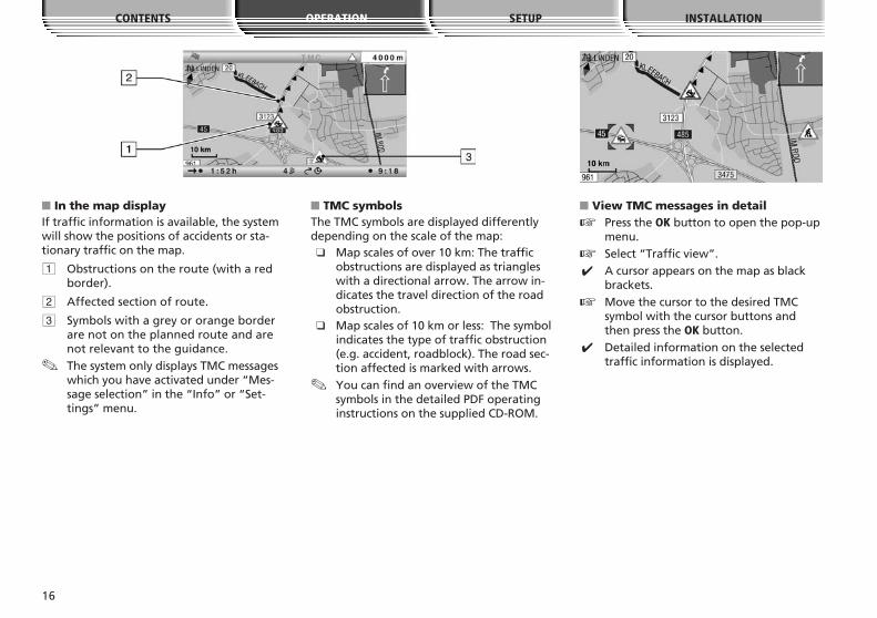
■ In the map displayIf traffic information is available, the systemwill show the positions of accidents or sta-tionary traffic on the map.
1 Obstructions on the route (with a redborder).
2 Affected section of route.
3 Symbols with a grey or orange borderare not on the planned route and arenot relevant to the guidance.
✎ The system only displays TMC messageswhich you have activated under “Mes-sage selection” in the “Info” or “Set-tings” menu.
■ TMC symbolsThe TMC symbols are displayed differentlydepending on the scale of the map:❑ Map scales of over 10 km: The traffic
obstructions are displayed as triangleswith a directional arrow. The arrow in-dicates the travel direction of the roadobstruction.
❑ Map scales of 10 km or less: The symbolindicates the type of traffic obstruction(e.g. accident, roadblock). The road sec-tion affected is marked with arrows.
✎ You can find an overview of the TMCsymbols in the detailed PDF operatinginstructions on the supplied CD-ROM.
■ View TMC messages in detail
☞ Press the OK button to open the pop-upmenu.
☞ Select “Traffic view”.
✔ A cursor appears on the map as blackbrackets.
☞ Move the cursor to the desired TMCsymbol with the cursor buttons andthen press the OK button.
✔ Detailed information on the selectedtraffic information is displayed.
16
OPERATION SETUP INSTALLATIONCONTENTS
■ In the symbol display
1 TMC symbol of the next road obstructionon the planned route.If a number of obstructions exist, this isindicated by means of a second TMCsymbol which is partially obscured bythe first.
2 Length of the section in which the trafficobstruction is located.If you are already located in the af-fected section: distance to end of thesection of route with the road obstruc-tion.
3 Distance to the next road obstructionon the planned route.
4 Simplified presentation of the route(black bar) and location of the road ob-struction (red segment). Vehicle posi-tion is shown as a circle with an arrowinside.
✎ The system only displays TMC messageswhich you have activated under “Mes-sage selection” in the “Info” or “Settings”menu.
✎ In the case of urgent traffic messageswithin a radius of 50 km of the vehicle’scurrent position, a special message ap-pears on the screen (e.g. vehicle onwrong carriageway). This message canbe hidden by confirming with the OKbutton. In addition, this information isprovided as an audible message.
✎ Road obstructions on the route are onlydisplayed when the guidance function isactivated.
Dynamic Route Planning –DRPWith the help of the TMC traffic information,the dynamic route planning – DRP – integratesthe entire traffic situation in an adjustableradius (traffic horizon) around the currentposition into its calculation of the route. If atraffic obstruction (e.g. stationary traffic) isreported via TMC for the planned route, thenavigation system will analyse the informationand calculate the anticipated delay.If there is a traffic problem on the plannedroute, you will be informed of this by thenavigation system and may decide whetherthe system should take a detour by changingthe route in order to avoid the segment con-cerned or whether it would be more sensiblejust to drive through the problem.The basis for the possible delay due to a traf-fic obstruction and calculated by the naviga-tion system is data that the system receivesvia the currently selected TMC station. Theactual delay may deviate from the calculation.
17
OPERATION SETUP INSTALLATIONCONTENTS
If you have activated the automatic mode,the system automatically plans the route sothat you are guided extensively around theroad obstructions without the system issuinga message.During guidance, the system checks continu-ously on the basis of the traffic informationwhether there is a better route for routeguidance and a new route is sometimes cal-culated, for example, if a traffic jam has dis-appeared.Depending on the setting in the dynamicroute planning, there are two different typesof detour:
■ Extensive detour(with activated DRP only)
As soon as the navigation system has receivedinformation about one or more traffic ob-structions via RDS-TMC that would mean arelatively long delay for navigation to yourdestination, the system offers you the optionwell in advance of detouring the traffic ob-structions extensively.
✎ The criteria that influence a new planningof the route (re-routing level, traffic ho-rizon and entire delay) can be set under“Settings –> Dynamic route”.
✎ It is possible to replan the route manuallyat any time in light of the current trafficsituation with the “Plan new route”menu item on the guidance screen.
■ Local detour(with deactivated DRP only)
With the local detour, it is possible to bypassthe next traffic obstruction ahead which isannounced by TMC.As soon as you have arrived up to approx.50 km from the road obstruction, you willreceive an appropriate message.
✎ With the “Local detour” menu item onthe guidance screen, you can bypass theimminent road obstruction if required.
■ Activating dynamic route planning
☞ Select “Info” in the Start menu.
☞ Select “Route criteria” in the Info menu.
☞ Activate “Dynamic route”.
☞ Select “Return” to save the setting.
Via pointsIf you wish to visit other locations en routeto the entered destination address, these canbe stored as via points. The navigation systemthen plans the route to include the via pointsin the given sequence before the destinationaddress is reached.
■ Entering via points
☞ Select “Via points” in the navigationmenu.
✔ The “Via points” menu is displayed.
☞ Enter the via points as described underDestination input.
In the “Via points” menu, the following op-tions are also available:❑ Store via point: Stores the currently en-
tered via point.❑ List via points: Displays the list of previ-
ously entered via points.❑ Delete via point: Deletes via points from
the list of via points.
OPERATION SETUP INSTALLATIONCONTENTS
18
■ Defining a flexible route pointAs well as the normal via points, you can alsoask the navigation system to plan the routeso that the route passes as close as possibleto a specific point on the map.
☞ Select the map display during guidance.
☞ Move the cursor with the cursor buttons4, 6,8 or2 to the point on the mapwhich you would like to define as a flex-ible route point.
☞ Press OK.
☞ In the pop-up menu, select “Store –>Flexible route point”.
✎ You can only define one flexible routepoint.
✎ A flexible route point can only be de-fined via the map display when theguidance function is activated.
✎ The flexible route point is deleted assoon as you enter a new via point (seeabove) or stop the guidance function.
✎ In contrast to a normal via point, you donot receive a message when you havereached the flexible route point.
■ Deleting a flexible route point
☞ Select “Info” in the Start menu.
☞ Select “Via points” in the Info menu.
☞ Select “Delete flexible route point”.
ToursThe Tours menu provides you with the optionof driving to a series of various destinationsone after the other without having to entereach destination individually.You only need to enter the individual stagesof the tour once via the destination input orthe address book and store this tour under afreely selectable name.The tour memory can store a total of 7 tourseach with a maximum of 10 stages.
☞ Select “Via points” in the navigationmenu.
☞ Select “Tour editor” in the pop-up menuthat appears.
✔ The “Tour editor” menu is displayed.
☞ Select “New tour” to create a new tour,or:
☞ select one of the saved tours to displayoptions for this tour.
The following options are available in thepop-up menu:❑ Return: Returns to the Tour menu.❑ Start tour: Starts navigation to the first
stage of the tour.❑ Start tour at: Starts the selected tour from
a certain stage.❑ Start reverse: Starts the selected tour in
reverse from the last stage.❑ Show list: Displays the stages of the se-
lected tour.❑ Edit tour: Opens the menu for editing
the selected tour.
■ Entering new tour
☞ Select the “New tour” menu item in theTours menu.
✔ This displays the menu for editing thenew tour.
☞ You can now enter tour stages (inter-mediate destinations).
OPERATION SETUP INSTALLATIONCONTENTS
19
Address bookThe navigation system provides the capabilityto store at least 200 destination addresses ina personal address book. The address book isdivided into the two categories “Private”and “Business”.You can also store an address for quick access(e.g. via the remote control) under “Home”and “Work”.With the “Retrieve address –> Prev. destina-tions” option, you can also call up the previousaddresses used for guidance.
Calling up the address book☞ Select “Address book” in the “Naviga-
tion” menu or in the “Via points”menu, if you would like to use the ad-dress book for entering via points.
✔ A pop-up menu with the following op-tions appears:
❑ Retrieve address: Loads an address alreadystored in the address book as the desti-nation or as a via point.
❑ Store address: Stores the currently enteredaddress in the address book.
❑ Delete address: Deletes an address or allthe addresses in a selected categoryfrom the address book.
❑ Store car position: Stores the current ve-hicle position in the address book.
Storing addresses☞ Enter the address (see destination entry).
☞ Select “Store address” and confirm withthe OK button.
☞ Select the address book category andconfirm with the OK button.
PC Copy ToolThe PC Copy Tool enables you to transfermap and travel guide data or language filesfrom the DVD supplied to SD memory cards.Detailed information on the functions of thePC Copy Tool can be found in the program’sonline help.
20
OPERATION SETUP INSTALLATIONCONTENTS
Adapting navigationsystemYou can change several settings to adapt thenavigation system to meet your personal re-quirements. For a detailed description of allfunctions, please refer to the operating in-structions on the DVD/CD-ROM.
Map viewActivating and changing settings for the au-tomatic map scale.If Automatic is activated, the scales are speci-fied for the following regions:❑ Highway❑ Rural areas❑ Urban areas
Screen configurationSetting the following screen properties:❑ Status lines❑ Day colour❑ Night colour❑ Setting the dependency of the colour
scheme on the vehicle lighting:– Automatic switching (depending onthe setting of the headlights)– Always day colours– Always night colours
Message selectionSelection of the type of TMC traffic messagesthat should be displayed by the navigationsystem.
☞ Store the modified selection list with“Store”.
✎ Urgent traffic messages cannot be dese-lected.
Route criteriaVarious criteria can be selected for route cal-culation:❑ Fast: Suited to all situations.❑ Short: Recommended for trips within
cities.❑ Main roads: Recommended if you prefer
routes via motorways.❑ No main roads: Recommended if you
prefer to avoid routes via motorways.
✎ The symbol for the selected route crite-rion is displayed in the status line.
You can also activate the following routeoptions:❑ Minimize toll roads❑ Minimize ferry usage❑ Minimize tunnel usage❑ Dynamic route: Activates/deactivates the
dynamic route planning.
✎ You can find the settings for the dy-namic route planning under “Dynamicroute”, see below.
Dynamic routeYou can set the following parameters for thedynamic route planning:❑ Re-routing level: Use this setting to spec-
ify whether or not the navigation sys-tem should plan a detour in the eventof traffic obstructions. Five levels areavailable. The lowest level (1) meansthat the direct route should go throughthe stationary traffic depending on theconditions and the anticipated delay. Ifthe highest level is selected, an alterna-tive route should be planned in mostcases.
✎ Level 3 is a standard setting for dynamicroute planning. It is the factory setting(default).
21
OPERATION SETUP INSTALLATIONCONTENTS
❑ Traffic horizon: This setting determinesthe radius in which the navigation systemshould take traffic obstructions into ac-count when planning your route.
❑ Entire delay: Use this value to indicatethe anticipated delay time due to a traf-fic obstruction at or above which thenavigation system should suggest that anew route be planned.
✎ The anticipated delay is calculated onthe basis of the data received from theTMC station and may deviate from theactual situation.
❑ Automatic mode: When this function isactivated, the dynamic route planningautomatically guides you around trafficjams. There is no further query.
Speed warningSettings for the messages and warnings ifthe statutory or manual speed limits are ex-ceeded:❑ Warning … over limit: Setting for the tol-
erance value for exceeding the statutoryspeed limits stored on the navigation SDcard. When the set value is exceeded,the speed display in the status line is dis-played red.
✎ For this purpose, the speed display inthe status line must be activated. Seealso the “Screen config. –> Status lines”section.
✎ Availability of the legal speed limit de-pends on the navigation SD card usedand on the relevant country.
A WARNING: No responsibility is acceptedfor the correctness of the speed limit infor-mation provided by the navigation system;it may not always reflect the currently validregulations. Always observe the applicablelegal speed limits and traffic regulations. Thevehicle speedometer must always be givenpriority for display of the vehicle speed.
❑ Warning at: Setting of an absolute valuefor a speed warning. A warning is dis-played when this value is exceeded.
✎ This function is suitable e.g. in the caseof a speed limit for winter tyres.
❑ P. sp. lim. warn. on/off: Activates/deacti-vates an audible message for the speedwarning.
Remote controlSettings for the support of various remotecontrols:
☞ Activate the remote controls with whichyour system can be operated (e.g. if youalso use a steering wheel remote control).
FAVOURITE functionDefinition of the functions which should beassigned to the FAVOURITE button on theremote control. It is possible to select onefunction from the function list for both theshort and the long press of the button.
22
OPERATION SETUP INSTALLATIONCONTENTS
General settingsThe following options are available in the“General settings” menu:
■ LanguageSelection of the language for menus andvoice information.
✎ The language for menus can be set in-dependently of the language for navi-gation instructions.
✎ An SD card with the corresponding lan-guage files is needed for loading a lan-guage other than the two languagefiles displayed.The language files can be transferredfrom the supplied DVD-ROM to an SDcard using the PC Copy Tool.
■ Audible settings.Settings for the audible guidance messages:❑ SDVC: Adjustment for speed-dependent
volume increase.❑ Volume: Setting of the volume of the
guidance messages.❑ Voice on/off: Activates/deactivates the
audible guidance messages.
■ Measuring unitsSetting of time and date format, measuringunits for distance specifications and adjust-ment of the current time zone.
■ Device configurationConnection settings which have to be carriedout once when the system is installed and/orin the case of subsequent system upgrades.
■ Shut-down timerSetting of the after-running time for thenavigation computer (sensible e.g. for shortintermediate stops).
System informationThe following options are available in the“System information” menu:❑ Diagnosis: Code-protected menu for in-
stallation and service purposes.❑ Default settings: Resets the user-specific
settings to the factory values.❑ Configuration: Display of unit identifica-
tion and hardware and software versions.❑ Speed correction: The navigation system
uses an average cruising speed to calcu-late the remaining travel time and theestimated time of arrival. If required,you can adapt this speed to your actualaverage speed. However, we do not rec-ommend you deviate significantly fromthe standard value of 100 %.
Info pointsSelection and activation/deactivation of themessages concerning info points (e.g. touristattractions, petrol stations, etc.).
23
OPERATION SETUP INSTALLATIONCONTENTS
TroubleshootingIn very rare cases, it can happen that yourmultimedia system does not function as youwould expect. Before you contact customerservice, please read the detailed operatinginstructions on the DVD-ROM and review thefollowing checklist, as an apparent malfunc-tion can possibly be remedied quickly.
Symptoms Possible cause/remedy
System does not start, screen dark. Ignition switched off:
• Switch on the ignition.Ignition is already switched on, and system is on stand-by:
• Press one of the cursor buttons, the OK button, or the menu buttonon the remote control.
The system switches itself off after aperiod of normal operation.
At extremely high or low temperatures, the system is automaticallyswitched off to protect against damage. It switches on again as soonas the temperature has returned to normal.
System does not react to actuation ofthe buttons if remote control is not inits active holder.
No batteries inserted or batteries empty:
• Replace the batteries in the remote control, or install the remotecontrol in its holder.
Guidance information not audible. • Check whether “Audible information” has been activated in the“Settings” menu.
• Check whether “Volume” in the “Settings” menu is set to minimum.If no external speaker is connected:
• Check the volume setting of the monitor.
Some of the symbols or specificationsshown in the operating instructions arenot displayed in the status line.
• Activate the required specifications in the “Settings–> Screen config. –> Status line” menu.
Colour of the satellite symbol in thestatus line is constantly red.
No GPS reception.
• Ensure that the GPS antenna is not obscured by any objects.
Current time in the status line is incor-rect.
• Set the correct time zone in the “Settings –> General settings –>Measuring units” menu.
Guidance is not accurate. An accuracy of 50 m falls within the specified tolerance limits. Pleasecontact an authorised dealer if greater inaccuracies occur repeatedly.
Displayed position does not correspondto actual vehicle position.
Problems with GPS reception persist. The position is corrected auto-matically as soon as GPS reception is satisfactory.
• If necessary, wait a few minutes.
• Have your installation workshop verify that the mounting angle ofthe navigation computer has been set correctly.
Directions do not correspond to the ac-tual traffic conditions.
It is possible that the car’s position as calculated by the navigationsystem is not currently correct. Traffic routing may have beenchanged and no longer corresponds to the information on the navi-gation data medium.
“TMC” logo in the status line is perma-nently red, and no traffic informationis displayed on the map.
Poor/disrupted TMC reception.
24
OPERATION SETUP INSTALLATIONCONTENTS
Symptoms Possible cause/remedy
System reports “Wrong or defectmedia!”.
Inserted SD card is not suited to your system.
System reports “System error”. Your system requires service.
• Please contact your installation workshop or your dealer.
25
OPERATION SETUP INSTALLATIONCONTENTS
Installation
Important notesA The system must only be installed bytrained personnel.
A Observe automotive industry qualitystandards.
A Fire hazard. When drilling, take care notto damage concealed wiring harnesses, thefuel tank or fuel lines.
A Never drill into supporting or safety-rele-vant body parts.
It is essential to observe the following wheninstalling components in the passenger com-partment:
A Ensure that the driver has a clear all-roundview.
A Increased risk of injury in the event of anaccident. Do not install components in theinflation range of the airbag or in areaswhere the head or knees may knock againstthem.
A Only install the unit in vehicles with a12-V on-board voltage and negative pole onthe vehicle body. Risk of malfunction, damageand vehicle fire if installed in vehicles withother electrical systems (e.g. 24 V withoutsuitable converter).
System componentsAt least the following components are re-quired for installation:❑ Navigation computer❑ GPS antenna with cable❑ Power supply cable❑ IR remote control❑ Monitor with monitor cable❑ Map software on SD card
■ Accessories❑ RCD 5400: Active remote control
holder. The remote control works with-out batteries in the active holder.
❑ MA 6500: TMC antenna❑ ML 5100: External loudspeaker❑ Second SD card (not a VDO Dayton
accessory)
Take safety precautionsA Before starting work, disconnect the earthlead from the negative terminal of the vehi-cle battery in order to prevent short circuits.At the same time, follow the vehicle manu-facturer’s safety instructions (alarm system,airbag, immobiliser, radio coding, etc.).
Selecting the installationlocation❑ For access to the two SD card slots, suffi-
cient clearance of at least 40 mm mustbe available in front of the navigationcomputer.
❑ A rigid connection to the vehicle body isa prerequisite for correct functioning ofthe system
26
OPERATION SETUP INSTALLATIONCONTENTS
Adjusting the gyro sensorThe PC 5200 can be installed within a rangefrom -90 to +90 degrees. Before final instal-lation of the computer, the gyro-sensor mustbe adjusted to the relevant installation posi-tion in the navigation computer.
☞ Set the gyro-sensor angle to the existinginstallation position using a coin or simi-lar suitable object on the side of thenavigation computer.
✎ Deviations of -10 to +10 degrees in thesensor settings can be compensated bythe navigation computer. Larger devia-tions may result in malfunctions.
✎ The navigation computer can also be in-stalled overhead. To adjust the naviga-tion computer for the overhead installa-tion see “Adapting the system” onpage 30.
Securing the computerThe navigation computer can be installed atvarious installation locations (e.g. in the glovecompartment, in the luggage compartmentor under the seats).
✎ When deciding on a suitable installation,good heat dissipation should also betaken into account. For example, do notcover computer with carpet, as thehousing acts as a heat sink.
☞ Secure the computer in the desired in-stallation location using the screws sup-plied.
✎ Alternatively, the computer can also besecured to a smooth surface using thedouble-sided adhesive tape supplied.
Installing the GPS antennaThe GPS antenna may be installed in the pas-senger compartment, for example on thedashboard or the rear shelf. The antennaneeds to have unrestricted “visual contact”to the sky.
✎ Vehicles with metallised windows shouldhave the antenna installed on the bootlid, on the roof or in the plastic bumper.
✎ To guarantee the functioning of the an-tenna, maintain a minimum distance of10 cm to any metal parts (window frame,etc.) during installation.
✎ The mounting surface must be free ofdust and grease.
✎ The installation temperature should beat least 15° Celsius so that the adhesivestrip can develop its full adhesivestrength.
☞ Place the antenna with the supplieddouble-sided adhesive strip onto thecleaned surface and press firmly intoplace.
27
OPERATION SETUP INSTALLATIONCONTENTS
Remote control holder■ 1. Sticking on the holder
☞ Stick the supplied adhesive pad ontothe area provided on the holder, thenstick on the holder, pressing firmly.
✎ The mounting surface must be free ofdust and grease.
✎ The installation temperature should beat least 15° Celsius so that the adhesivestrip can develop its full adhesivestrength.
■ 2. Screwing on the holder
☞ Screw the holder directly to the installa-tion position using two suitable screws.
Making the electricalconnectionsInstall all cables with care. For wiring details,refer to the connection diagram and to theadjacent table.
Power supply cable(ISO chamber A), Fig. 2:
A Only connect electrical signals to suitableconnecting points in the vehicle.
A If connection is made directly to thebattery, protect the positive lead (red lead)with a 10 A fuse close to the battery (approx.10 - 15 cm).
☞ Connect the free wire ends A4, A7 andA8 of the power supply cable to suitableconnection points in the vehicle in ac-cordance with the connection diagramand the table.
✎ Do not cut non-assigned wires. Instead,wind them together and secure to oneside. They may be required for retrofit-ting additional functions.
Speedometer signal(ISO chamber A):Depending on the type of speedometer signal,either the digital (A1) or the analogue (A3)input must be selected. Check speedometersignal using an oscilloscope if necessary.Many vehicles are equipped with a speedo-meter signal on one of the radio connectors.For further information contact your vehicledealer or our hotline.If your vehicle is not equipped to produce anappropriate speedometer signal, an optionalspeed sensor can be installed. This is availableas an accessory from your installation service.
A Never collect the speedometer signalfrom the ABS control!
28
OPERATION SETUP INSTALLATIONCONTENTS
Pin Cable colour Connection
A1 Black/white Speedometer signal input, digital (long cable) ❍
A2 White/yellow Switch input reversing signal (reversing light positive) ●
A3 Black/white Speedometer signal input, analogue (short cable) ❍
A4 Red + 12 V permanent positive; terminal 30 (where necessary via 10 A cable fuse) ●
A5 White/blue “Accessory” switch input ❍
A6 Grey Low beam positive ●
A7 Purple +12 V ignition positive; terminal 15 (without switch-off on starting engine) ●
A8 Brown Battery negative; terminal 31 ●
● = Connection required❍ = Connection optional
■ Digital (standard):
☞ Route the black/white A1 cable of thewiring harness to the speedometer signalpick-up point. Refer to the vehicle-specificdata sheets for location and connectiondetails (available on CD-ROM).
Digital speedometer signal requirements:❑ Frequency: 0 Hz - 4 kHz square-wave
signal (no inductive sensor)❑ Low - level: < 1 V❑ High - level: 4 V - 24 V
■ Analogue (for retrofitted speedometersenders and magnetic sensors):
☞ Connect the short black/white A3 cable(directly at ISO chamber A connector) ofthe wiring harness to the output of thespeedometer sensor or the magneticsensor.
■ Operation without speedometersignal
Operation of the navigation system is possiblewithout a speedometer signal. However, inthe absence of a speedometer signal the fol-lowing functional restrictions may arise:❑ Inaccurate navigation❑ Inaccurate or invalid information in trip
computer❑ Limitations with regard to SDVC (speed-
dependent volume control)
Other signals (ISO chamber A):☞ Connect the white/yellow wire (A2) to a
suitable point of the reversing signallead (positive lead of reversing lamp).
☞ Connect the grey wire (A6) to a suitablepoint of the low beam (not to the dashpanel illumination!).
✎ Connection to the dash panel illumina-tion may result in malfunctions of thenavigation system (e.g. extremely slowreactions to operating steps and systemcrashes.).
Connecting system components(ISO chamber B)
■ Active remote control holderRCD 5400 (accessory):
☞ Connect the remote control cable plugto the mini-DIN socket on the signalcable.
■ Loudspeaker (accessory):
☞ If required, connect separate loudspeakerto signal cable (B5 and B6). The loud-speaker impedance should be between4 and 8 Ohm.
■ Loudspeaker mute/MUTE (option):
☞ Connect the brown/white wire (B4) ofthe signal cable to the MUTE input ofthe car radio.
Playback of voice messages via thevehicle loudspeakerFor playback of the acoustic guidance in-structions via the front left vehicle loud-speaker, an MA 1300 adapter cable (acces-sory) can be connected between the loud-speaker lead and the audio output of thenavigation computer.
☞ Connect the brown/white wire (B4) ofthe signal cable to the MUTE input ofthe adapter cable.
29
OPERATION SETUP INSTALLATIONCONTENTS
Mounting the computer1. Connect the GPS antenna to the “GPS”
socket and the TMC antenna (accessory)to the “TMC” socket.
2. Connect the power supply cable to theISO socket A’ of the navigation computer.
3. If used: Connect the signal cable to theISO socket B’ of the navigation computer.
4. Connect the monitor cable to the moni-tor socket D’ of the navigation computer.
Initial operation1. Reconnect the battery.2. Insert SD card with the map data into
one of the computer’s SD card slots.3. Insert batteries in the remote control
battery compartment.If an active holder (accessory) is beingused for the remote control, in theholder the remote control also workswithout batteries.
4. Park the vehicle outdoors to ensure un-impeded GPS reception.
5. Switch on the ignition.The LED on the navigation computermust light up.The screen display appears (informationon the safe use of the system).
6. Confirm the user information using theOK button on the remote control.The main menu appears.
7. Wait for a few minutes with the ignitionswitched on until the navigation systemhas adequate GPS reception.The integrated GPS receiver requiresapprox. 2 - 10 minutes following the firststart-up to receive the system time andto calculate an adequately accurate GPSposition.
Adapting the system☞ Select “Settings –> System Information
–> Diagnosis –> Code” (see also operat-ing instructions).
☞ Enter the code “6330”.
✎ You can now perform the necessary ad-aptation of the navigation computer tothe installation position and configura-tion of the overall system.
■ Display adaptation
☞ Select “Screen format”, and set the navi-gation computer to the relevant monitortype (4:3 or 16:9).
■ Setting the language for the displaytext and voice messages
A description on loading languages can befound in the section entitled “Settings” inthe detailed operating instructions on theDVD-ROM supplied.
■ Adjusting the installation positionWhen the computer is installed overhead:
☞ Select “Installation position” and activatethe corresponding option.
30
OPERATION SETUP INSTALLATIONCONTENTS
Checking the vehiclefunctionsA Check the safety-relevant vehicle functionsonly when the vehicle is stationary, or movingat low speed. Only perform the check in anopen area.Brake system, lights, speedometer, trip com-puter.Restore perfect functioning of the electricalsystem (clock, trip computer, alarm system,airbag, immobiliser, radio coding etc.).
Checking the navigation functionsCheck the following functions in the station-ary vehicle:
■ Remote control (batteries inserted)Press the buttons on the remote control andwatch for the reaction on the navigation sys-tem.
■ Active remote control holderInsert the remote control into the holder(without batteries):The navigation system must react to actua-tion of the buttons.
■ Night/day colour displaySwitch on the low beam:The navigation system should switch fromday to night colours.
■ GPS receptionCall up the “Map” option in the main menu.The map with the calculated vehicle positionis displayed. The GPS reception status is indi-cated at the centre of the bottom status line.As soon as adequate GPS reception is ensured,the colour of the GPS logo changes from redto black. There should be a minimum of 4satellites received.
■ TMC receptionThe reception status for the Traffic MessageChannel is indicated at the centre of the topstatus line. TMC reception is not availablewhen “TMC” is written in red.
CalibrationAs soon as adequate GPS reception is avail-able (green GPS logo), perform a short testdrive (approx. 10 minutes) on digitised roadsin order to calibrate the system. Calibrationtakes place fully automatically. Turn off sev-eral times and drive through a number ofjunctions.You can then check whether the navigationsystem indicates the correct vehicle positionin the map display.
■ Speedometer signalThe functioning of the speedometer signalcan be tested using the trip computer func-tion of the navigation system. The trip com-puter must show the current vehicle speedduring driving. The wrong speed may be in-dicated prior to final calibration.
HotlineHotlines are available in many countries tohandle queries regarding the multimediasystem.On the Internet: www.vdodayton.com