Delft University of Technology Bachelor Thesis Ar.Drone Autonomous Control and Position Determination Jacco van der Spek Mario Voorsluys 4002512 4048482 June 2012 Faculty of Electrical Engineering, Mathematics and Computer Science
Transcript
DelftUniversityof
Techn
ology
Bachelor ThesisAr.Drone Autonomous Control and Position Determination
Jacco van der Spek
Mario Voorsluys
4002512
4048482
June 2012
Faculty of Electrical Engineering,Mathematics and Computer Science
Bachelor Thesis V1.0 (Wednesday 27th June, 2012)
This Bachelor thesis is made using LATEX in Computer Modern Roman 11pt.
Preface
For a not yet established Unmanned Aerial Vehicle (UAV) competition aprototype UAV is needed. This UAV has to be able to recognize a movingvehicle. When this vehicle is recognized the UAV should be able to keeptracking the vehicle. This prototype will be used to show that the challengesof the competition are feasible. It will also be used to make promotionalmaterials like videos.
Two teams will be working on this prototype; a team of ten students ofAerospace Engineering and a team of six students of Electrical Engineering.The Aerospace Engineering students will design a fixed wing UAV. We,as Electrical Engineering students, will develop the electrical system. Adesign brief was drafted to state the requirements we want to meet (seeAppendix A).
The development of the electrical system is split up in three sub-groupsof two students. One team is responsible for the development of a dataconnection to a ground station. They also visualize the information thatis exchanged between the UAV and the ground station. The second teamdevelops an intelligent camera system that recognizes and tracks the vehicle.We, the authors of this thesis, will develop a sensor system and enable ourtest UAV to fly autonomously. A functional block diagram of the wholesystem can be found in Appendix B where the elements of our subsystemare highlighted. The three subsystems will form one system that, we think,will deliver a proof of concept for our clients: T. Durieux BSc and J. MelisBSc.
Jacco van der Spek & Mario VoorsluysDelft, June 2012
i
Acknowledgements
We would like to thank the following people and organisations:
Our supervisor dr. ir. C.J.M. Verhoeven for his continued enthusiasm and(financial) supportT. Durieux B.Sc. and J. Melis B.Sc. for their support and the assignmentThe Microelectronics Department for the provision of two quadrocoptersand budgetThe Raspberry Pi foundation for their support with a Raspberry Pi.Our team members for the collaboration and great time together
ii
Summary
For a prototype UAV an object recognition and tracking system had to bedeveloped. This system has been developed by a team of six Electrical Engi-neering students. The system has been tested on a Parrot AR.Drone, whichis a commercially available drone. The system has been divided in threesubsystems and each subsystem has been designed by a team of two people.The first subsystem creates a data connection between the system and aground station and displays this data in a Graphical User Interface. Thesecond subsystem is tracking a moving object and calculating the positionof this object. The third subsystem is a system that determines the positionof the AR.Drone and controls the AR.Drone. The third subsystem has beendesigned by the two writers of this thesis.
The aim of this thesis was to select a suitable positioning method anddesign an autonomous control for the AR.Drone. Therefore two main ques-tions were formulated:
1. What positioning method should be used for determining the positionof a UAV?
2. How can the AR.Drone have autonomous control?
It is important to know the position (including the altitude) of the UAV forthree reasons. The first reason is a safety reason: by knowing the positionit is able to prevent crashes by adjusting the course of the UAV. The secondreason is that for the calculation of the position of the object it is necessaryto know the altitude. The third reason is that the data communication teamwanted to display the location of the UAV on a map. In order to track therecognized object, an autonomous control for the AR.Drone was designed.This control enables the AR.Drone to follow the moving object.
To answer the two main questions, first research was done into appro-priate positioning methods and AR.Drone control options. Then the resultsof this research were used to implement the desired positioning and controlmethods for the AR.Drone. Thereafter the implementation was tested.
iii
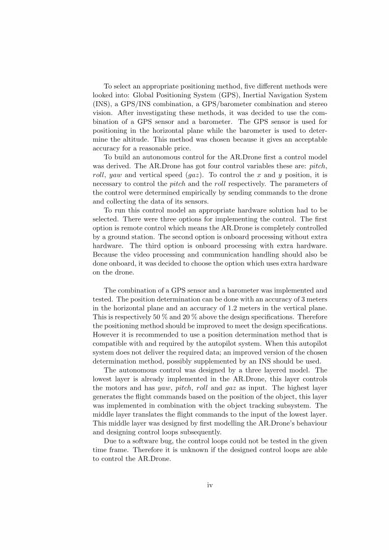
To select an appropriate positioning method, five different methods werelooked into: Global Positioning System (GPS), Inertial Navigation System(INS), a GPS/INS combination, a GPS/barometer combination and stereovision. After investigating these methods, it was decided to use the com-bination of a GPS sensor and a barometer. The GPS sensor is used forpositioning in the horizontal plane while the barometer is used to deter-mine the altitude. This method was chosen because it gives an acceptableaccuracy for a reasonable price.
To build an autonomous control for the AR.Drone first a control modelwas derived. The AR.Drone has got four control variables these are: pitch,roll, yaw and vertical speed (gaz). To control the x and y position, it isnecessary to control the pitch and the roll respectively. The parameters ofthe control were determined empirically by sending commands to the droneand collecting the data of its sensors.
To run this control model an appropriate hardware solution had to beselected. There were three options for implementing the control. The firstoption is remote control which means the AR.Drone is completely controlledby a ground station. The second option is onboard processing without extrahardware. The third option is onboard processing with extra hardware.Because the video processing and communication handling should also bedone onboard, it was decided to choose the option which uses extra hardwareon the drone.
The combination of a GPS sensor and a barometer was implemented andtested. The position determination can be done with an accuracy of 3 metersin the horizontal plane and an accuracy of 1.2 meters in the vertical plane.This is respectively 50 % and 20 % above the design specifications. Thereforethe positioning method should be improved to meet the design specifications.However it is recommended to use a position determination method that iscompatible with and required by the autopilot system. When this autopilotsystem does not deliver the required data; an improved version of the chosendetermination method, possibly supplemented by an INS should be used.
The autonomous control was designed by a three layered model. Thelowest layer is already implemented in the AR.Drone, this layer controlsthe motors and has yaw, pitch, roll and gaz as input. The highest layergenerates the flight commands based on the position of the object, this layerwas implemented in combination with the object tracking subsystem. Themiddle layer translates the flight commands to the input of the lowest layer.This middle layer was designed by first modelling the AR.Drone’s behaviourand designing control loops subsequently.
Due to a software bug, the control loops could not be tested in the giventime frame. Therefore it is unknown if the designed control loops are ableto control the AR.Drone.
iv
Contents
Preface i
Summary iii
List of Figures ix
List of Tables xi
List of Abbreviations xiii
1 Introduction 1
2 Choice for a position determination method 3
2.1 Possible position determination methods . . . . . . . . . . . . 3
5.1 Parameters of the AR.Drone model . . . . . . . . . . . . . . . 35
xi
xii
List of Abbreviations
gaz vertical speed
I2C Inter-Integrated Circuit
pitch turning around y-axis
roll turning around x-axis
yaw turning around z-axis
COTS Commercial Of The Shelf
CPU Central Processing Unit
ftp file transfer protocol
GLONASS Globalnaya Navigatsionnaya Sputnikovaya Sistema or GlobalNavigation Satellite System
GNSS Global Navigation Satellite System
GPL General Public License
GPRMC Global Position Recommended Minimum sentence version C
GPS Global Positioning System
IMU Inertial Measurement Unit
INS Inertial Navigation System
NMEA National Marine Electronics Association
SDK Software Development Kit
UART Universal Asynchronous Receiver/Transmitter
UAV Unmanned Aerial Vehicle
UDP User Datagram Protocol
xiii
USB Universal Serial Bus
WGS84 World Geodetic System 1984
xiv
Chapter 1
Introduction
UAVs (Unmanned Air Vehicles) are nowadays used for a wide range ofapplications ranging from rescuing people [1] to acting on a battlefield [2].For all these applications it is essential to know the position of the UAV.
There are various methods for determining the position of a UAV. It canbe done by using a GNSS (Global Navigation Satellite System) receiver [3].Another method used by [4] is INS (Inertial Navigation System). A thirdmethod combines these systems [4]. Hereby the INS is a complementarysystem of the GPS, the INS provides a high accurate position when theGPS accuracy is poor [5]. According to [5, 6, 7, 8, 9] the combination ofGNSS/INS is a good method for determining the position of a UAV. [10]and [11] propose the use of stereo vision to determine the position of a UAV.
Not only the position of a UAV is important, the determination of thealtitude is even more important. The aforementioned methods for deter-mining the position are also suited for determining the altitude of a UAV[5], [6]. [12] uses a barometer to measure the pressure. A method usedby [11] is stereo vision to determine the altitude. However GPS/INS andbarometer sensors are less suited for landing due to a too low accuracy [13].[13] proposes two methods for determining the altitude while landing: usinga wireless sensor network or using ultrasonic sensors. Another method formeasuring the altitude while landing is a circular mark placed on a runwaywhich is recognized by a camera [14].
Applications and systems for UAVs should also be tested. This is prefer-ably done as cheap as possible. In 2010 a low-cost commercial UAV appearedon the market, the AR.Drone [15]. This AR.Drone has proved to be usefulfor research [16]. The AR.Drone has been used as a research platform in[16, 17, 18, 19]. [16] mentions the possibility of embedding software in thedrone.
1
2
The aim of this thesis is to select a suitable positioning method and de-sign an autonomous control for an AR.Drone. The object recognition andtracking system that will be designed, will be tested on an AR.Drone. AnAR.Drone however does not contain a sensor for position determination [20].There are also no examples of AR.Drones that have autonomous control.Therefore this thesis aims on two main questions:
1. What positioning method should be used for determining the positionof a UAV?
2. How can the AR.Drone have autonomous control?
To answer these two questions, in chapter 2 a study will be done to selectan appropriate positioning method. In chapter 3 a study will be conductedfor a suitable control method for the AR.Drone. In chapter 4 the implemen-tation of both methods will be described. The test results will be presentedin chapter 5. Next the test results will be discussed in chapter 6. Finallychapter 7 will give the conclusion of this thesis and give some recommenda-tions for future research.
Bachelor Thesis Ar.Drone Autonomous Controland Position Determination
Chapter 2
Choice for a positiondetermination method
The aim of this chapter is to select an appropriate method for the determina-tion of the position of the AR.Drone. First several methods for determininga location will be described in section 2.1. Next an appropriate method,according to several criteria, will be chosen in section 2.2.
2.1 Possible position determination methods
In this section four different methods to determine a position will be de-scribed: GPS(subsection 2.1.1), INS(subsection 2.1.2), GPS with additionalsensors(subsection 2.1.3) and stereo vision(subsection 2.1.4).
2.1.1 Global Positioning System
GPS provides positioning, navigation and timing services. Two GPS po-sitioning services are provided: the Precise Positioning Service which isavailable to the military of the U.S. and its allies and the Standard Po-sitioning Service which is less accurate and provided to civil users. TheGPS Standard Positioning Service is defined as follows: “The SPS is a po-sitioning and timing service provided by way of ranging signals broadcastat the GPS L1 frequency. The L1 frequency, transmitted by all satellites,contains a coarse/acquisition (C/A) code ranging signal, with a navigationdata message, that is available for peaceful civil, commercial, and scientificuse” [21].
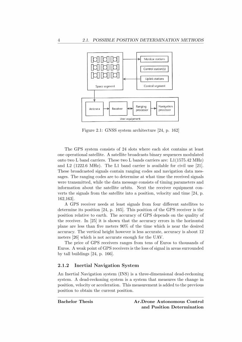
GPS is an elaboration of the Global Navigation Satellite System (GNSS)architecture. Besides GPS there are a few more elaborations of the GNSSarchitecture. Examples are GLONASS , the Russian version of GPS [22],and Galileo, a civil European initiative [23]. A schematic overview of theGNSS architecture can be found in Figure 2.1.
3
4 2.1. POSSIBLE POSITION DETERMINATION METHODS
Figure 2.1: GNSS system architecture [24, p. 162]
The GPS system consists of 24 slots where each slot contains at leastone operational satellite. A satellite broadcasts binary sequences modulatedonto two L band carriers. These two L bands carriers are: L1(1575.42 MHz)and L2 (1222.6 MHz). The L1 band carrier is available for civil use [21].These broadcasted signals contain ranging codes and navigation data mes-sages. The ranging codes are to determine at what time the received signalswere transmitted, while the data message consists of timing parameters andinformation about the satellite orbits. Next the receiver equipment con-verts the signals from the satellite into a position, velocity and time [24, p.162,163].
A GPS receiver needs at least signals from four different satellites todetermine its position [24, p. 165]. This position of the GPS receiver is theposition relative to earth. The accuracy of GPS depends on the quality ofthe receiver. In [25] it is shown that the accuracy errors in the horizontalplane are less than five meters 90% of the time which is near the desiredaccuracy. The vertical height however is less accurate, accuracy is about 12meters [26] which is not accurate enough for the UAV.
The price of GPS receivers ranges from tens of Euros to thousands ofEuros. A weak point of GPS receivers is the loss of signal in areas surroundedby tall buildings [24, p. 166].
2.1.2 Inertial Navigation System
An Inertial Navigation system (INS) is a three-dimensional dead-reckoningsystem. A dead-reckoning system is a system that measures the change inposition, velocity or acceleration. This measurement is added to the previousposition to obtain the current position.
Bachelor Thesis Ar.Drone Autonomous Controland Position Determination
CHAPTER 2. CHOICE FOR A POSITION DETERMINATIONMETHOD 5
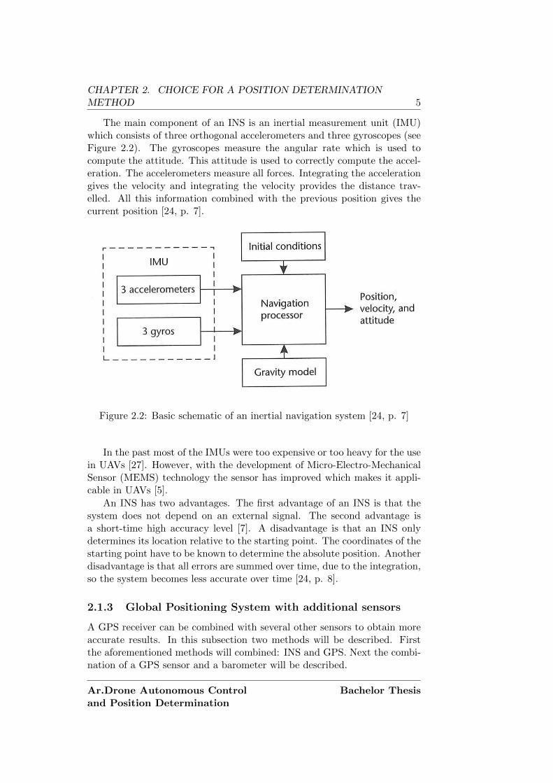
The main component of an INS is an inertial measurement unit (IMU)which consists of three orthogonal accelerometers and three gyroscopes (seeFigure 2.2). The gyroscopes measure the angular rate which is used tocompute the attitude. This attitude is used to correctly compute the accel-eration. The accelerometers measure all forces. Integrating the accelerationgives the velocity and integrating the velocity provides the distance trav-elled. All this information combined with the previous position gives thecurrent position [24, p. 7].
Figure 2.2: Basic schematic of an inertial navigation system [24, p. 7]
In the past most of the IMUs were too expensive or too heavy for the usein UAVs [27]. However, with the development of Micro-Electro-MechanicalSensor (MEMS) technology the sensor has improved which makes it appli-cable in UAVs [5].
An INS has two advantages. The first advantage of an INS is that thesystem does not depend on an external signal. The second advantage isa short-time high accuracy level [7]. A disadvantage is that an INS onlydetermines its location relative to the starting point. The coordinates of thestarting point have to be known to determine the absolute position. Anotherdisadvantage is that all errors are summed over time, due to the integration,so the system becomes less accurate over time [24, p. 8].
2.1.3 Global Positioning System with additional sensors
A GPS receiver can be combined with several other sensors to obtain moreaccurate results. In this subsection two methods will be described. Firstthe aforementioned methods will combined: INS and GPS. Next the combi-nation of a GPS sensor and a barometer will be described.
Ar.Drone Autonomous Controland Position Determination
Bachelor Thesis
6 2.1. POSSIBLE POSITION DETERMINATION METHODS
GPS/INS
GPS/INS combines the long-time high accuracy level of GPS with the short-time high accuracy level of the INS [7]. The combination of GPS and INSis implemented with the use of a Kalman filter. A Kalman filter is anestimation algorithm that uses a stream of measurements to estimate thedesired parameters [24, p. 55]. In [4] three methods for coupling a GPS andan INS are described. It appears that the combination of GNS and INS issuited for the use in UAVs according to [6, 27, 28].
The coupling of GPS/INS will provide much better accuracy than GPSor INS alone [6, 9]. The coupling can also provide a backup when theGPS signal is lost. Another advantage is that it is possible to obtain goodresults with low-cost sensors compared to normal sensors [5, 7, 9, 27, 28]. Adisadvantage is that for every coupling a Kalman filter has to be designed.The use of this Kalman filter will also require computing power.
Barometer
A barometer can be used to determine the altitude. Such a barometricaltimeter measures the air pressure pb. The height can then be calculatedwith (2.1).
hb =TskT
(pbps
)−RkTg0
− 1
+ hs (2.1)
Where ps and Ts are the surface pressure and temperature, hs is the heightat which they are measured. The gas constant R = 287.1Jkg−1K−1, kT =6.5x10⁻³Km−1 is the atmospheric temperature gradient and g0 = 9.80665ms−2
is the average surface acceleration due to gravity. (2.1) only applies atheights up to 10.796 km, above this another air temperature is assumed [24,p. 328]. This altitude measurement can be combined with the altitude ofthe GPS receiver or used instead of the altitude measurement of the GPSreceiver. [29] describes the use of an barometric altimeter for determiningthe altitude of an unmanned helicopter and proposes some improvementsfor the formula to determine the height.
The advantage of a barometer is a good accuracy, depending on thesensor, as low as one meter [24, p. 328]. Barometers are also affordablewhich is desirable when there is a small budget. A disadvantage is that therecan be errors because of the difference in true and modelled atmospherictemperature and pressure [24, p. 328]. Another disadvantage is the groundeffect in rotor driven applications described in [29]. It is expected that theground effect will be negligible on the position determination system becausethe sensor will be placed in the body of the UAV.
Bachelor Thesis Ar.Drone Autonomous Controland Position Determination
CHAPTER 2. CHOICE FOR A POSITION DETERMINATIONMETHOD 7
2.1.4 Vision based system
A stereo vision system can be used to determine the position, attitude andaltitude of a UAV [30]. In this system two cameras are, by a special mirrortechnique, focussed on the same ground plane (see Figure 2.3 for a schematicillustration). With algorithms the position of a point can be determined.By computing the image disparity between two stereo pairs a visible en-vironment can be reconstructed. With this information the attitude andaltitude of the UAV can be determined [11]. The position of the UAV isthen determined relatively to the starting point. In [10] two cameras areused to recognize landmarks with known coordinates which makes it possi-ble to calculate the absolute position. In [31] is explained that it is possiblefor a UAV to manoeuvre autonomous using video data for navigation.
Figure 2.3: Schematic illustration of a stereo vision system, surface of con-stant disparity, and collision-free cylinder. [11]
Depending on the used cameras a good accuracy can be achieved [11].An advantage of a vision based system is that the cameras can also beused for object avoidance [11]. A disadvantage is the need for two cameras,which can be expensive. Another disadvantage is the need to process allimages and the need for algorithms to compute the relative position whichmay require considerable computing power. A third disadvantage is thatweather conditions may influence or disable the system.
Ar.Drone Autonomous Controland Position Determination
Bachelor Thesis
8 2.2. CONSIDERATION OF ALTERNATIVES
2.2 Consideration of alternatives
2.2.1 Criteria
There are nine criteria which the positioning method should meet. Thesecriteria will be explained in this subsection, most of them will be based onthe design brief (Appendix A).
Commercial of the shelf
First of all the components should be commercial of the shelf (COTS) avail-able. Preferably the components should work right out of the box exceptfor soldering wires. This is because there is no need and time to design anew positioning system.
Complementary
The positioning method should be complementary to the sensors that arealready on the AR.Drone [20]. A positioning method is installed becausethe AR.Drone lacks sensors for determining the data that is needed by thetracking system and the ground station.
Accuracy
Based on the design brief an accuracy of 2 meters in horizontal direction and1 m in vertical direction should be achieved. The AR.Drone has got an ul-trasound altimeter [20] with a range of 6 meters. Because the system shouldbe able to operate on heights over 6 meters another positioning method forthe altitude is needed.
Absolute positioning
The position of the UAV should be known relative to Earth. This is impor-tant for displaying the position of the UAV on a map. It is also importantbecause it should be able to return to base, which is easier with absolutepositioning.
Weight and size
The whole electrical system should be less than 250 grams according tothe Aerospace Engineering group. The positioning system should not weighmore than 15 grams because that is feasible and then there is a larger marginon the weight of other components. Because there is little space in UAVs asmall positioning system is preferred.
Bachelor Thesis Ar.Drone Autonomous Controland Position Determination
CHAPTER 2. CHOICE FOR A POSITION DETERMINATIONMETHOD 9
Update rate
The final UAV will be flying at a speed of about 30 ms−1. To give a goodstatus of the position an update rate of at least 5 Hz is required. Whenflying in a straight line this corresponds to a distance of 6 meters coveredbefore a new update is available.
Power
The whole system should be able to operate one hour on a battery thatcan be fitted in a UAV. Therefore it is required that the positioning systemshould consume not more than 200mW. The higher the power consumptionof all components together is, the bigger battery is needed.
Vibrations
The positioning system should not be affected in its operations by vibra-tions. This means that solder does not release and that connectors do notdisconnect due to vibrations of the aircraft’s propulsion.
Price
All components that are ordered, are ordered on the budget of the team andthe TU Delft. Therefore the expenses should be kept reasonable. For thatreason the positioning system should cost no more than e 80,00.
2.2.2 Consideration
In this paragraph an overview will be given of the methods mentioned insection 2.1 and the criteria in subsection 2.2.1 are met. This will be donewith the help of Table 2.1. The information in Table 2.1 is based on thearticles of the previously mentioned sources. Based on Table 2.1, Table 2.2is created which summarizes the technical data in pluses and minuses. Thescores will range from −− (meaning very undesirable) to ++ (meaning verydesirable).
Ar.Drone Autonomous Controland Position Determination
Bachelor Thesis
10 2.2. CONSIDERATION OF ALTERNATIVES
Tab
le2.1:
Overv
iewof
position
ing
meth
od
san
dcriteria
Criteria
GP
SIN
SG
PS
/INS
GP
S/B
aroV
isionb
ased
CO
TS
yesyes
not
available
asa
mod
ule
yesn
otavailab
leas
am
od
ule
Com
plem
enta
ryyes
already
onb
oardp
artly,IN
Sis
on-
board
yesyes
Accu
racy
ha:<
5m,
vb:
12m
decrea
sesw
ithtim
eh
:<
1m
,v:<
2mh
:<
5m,
v:<
3mh
:<
2m,
v:<
2mA
bsolu
tep
ositio
n-
ing
yesn
oyes
yesn
o
Weigh
t<
12
gra
ms
inclu
d-
ing
anten
na
0gra
ms
<15
gram
s<
15gram
sd
epen
ds
onth
eu
sedcom
pon
ents
Up
date
rate
up
to10
Hz
50H
zG
PS
up
to10
Hz,
INS
up
to50
Hz
GP
Su
pto
10H
z,B
arou
pto
128H
z25
Hz
Pow
er100
mW
1m
W100
mW
100m
Wd
epen
ds
onth
eu
sedcam
erasV
ibra
tion
sn
oin
flu
ence
need
sfi
ltering
no
infl
uen
cen
oin
flu
ence
migh
taff
ectth
eim
-ages
Price
<e
60,00
<e
35,00
<e
95,0
0<e
80,00<e
40,00+
the
price
ofa
suitab
lem
icropro
cessor
ahorizo
nta
lbv
ertical
Bachelor Thesis Ar.Drone Autonomous Controland Position Determination
CHAPTER 2. CHOICE FOR A POSITION DETERMINATIONMETHOD 11
2.2.3 Final choice: Global Positioning System/barometer
After considering all alternatives it was decided to purchase the combina-tion of the GPS and the barometer. This might not be the best choice interms of accuracy but it is in terms of implementation and needed additionalresources. According to Table 2.2 GPS/Baro is overall the best solution.
The vision based method would be very hard to implement and wouldrequire extra processing power because all images have to be processed. Thecombination of GPS/INS would be the best solution for a reasonable priceif there are ready to use modules. These ready to use modules are howeverhard to find and really expensive and therefore not an option. Implement-ing a GPS and INS combination ourselves is also not an option because itwould require too much time. Because the very rapid degradation of the ac-curacy of an INS sensor this method is not very suitable for positioning use.Furthermore an INS sensor would deliver the relative position which is notideal. A GPS sensor is very inaccurate in the altitude which is importantdata for a UAV.
Therefore we decided to choose the GPS sensor combined with a barom-eter. This gives acceptable accuracy in horizontal and vertical direction ata reasonable price.
Ar.Drone Autonomous Controland Position Determination
Bachelor Thesis
12 2.2. CONSIDERATION OF ALTERNATIVES
Bachelor Thesis Ar.Drone Autonomous Controland Position Determination
Chapter 3
AR.Drone control
The aim of this chapter is to select an appropriate implementation for thecontrol of the AR.Drone. Therefore in section 3.1 a control model of theAR.Drone will be explained. Subsequently in section 3.2 a study is con-ducted on the different options for the hardware to control the AR.Drone.Finally in section 3.3 these options are compared and the best option ischosen.
3.1 Control loops
In this section a control model for the AR.Drone will be studied. Thereforefirst some background information on autonomous control of UAVs will begiven. Next the control model of the AR.Drone will be derived.
3.1.1 Layered model
In [32] a layered model to control autonomous UAVs is described. The firstlayer is the kernel control, responsible for asymptotic stability, the secondlayer is the command generator, responsible for generating flight commandsfor the kernel control, and the highest level is the flight scheduling. Thefunction of the flight scheduler is to generate a flight plan, flight tasks andreferences.
The AR.Drone has the first layer implemented. The drone receives flightcommands over a Wi-Fi connection and performs them. The angle stabi-lization and vertical speed are controlled by the software running on thedrone. However the AR.Drone does not have the second and the third layerimplemented. If this layer structure is to be used to make the AR.Droneautonomous, the second and third layer have to be implemented. In subsec-tion 3.1.2 the design of the second layer will be described. The third layer, inthis project, is partially human control and partially commands generatedby the target-tracking system.
13
14 3.1. CONTROL LOOPS
Figure 3.1: The directions and turning angles of the AR.Drone. Figurefrom [16]. The orientation of the drone is defined by its camera view. Atthe bottom of the picture the view of the bottom camera is displayed whileat the right the view of the front camera is displayed.
3.1.2 AR.Drone control model
As indicated in subsection 3.1.1 the second and third layer of the layeredmodel are not implemented in the AR.Drone. The third layer is designed incombination with [33]. The design of the second layer will be explained inthis subsection.
The second layer, also called the command generator, receives input froma higher layer (flight planner), and send commands to the lower layer (kernelcontrol) to reach the destination given by the flight planner [32]. The kernelcontrol of the AR.Drone is different from the kernel control developed in[32].
As the command generator has to generate commands that should beexecuted by the lower layer, the second layer will also be different. In thislayer structure, the controllers explained in [16] perform the function desiredfor the command generator.
To design the controllers of the command generator, it is necessary toknow more about the system dynamics and the control variables. [16] de-scribes how to control the drone with four different control loops. The firstis for position x, the second for position y, the third for z and the last oneis for the yaw. Figure 3.1 demonstrates this coordinate system relative tothe UAV.
The control variables for the AR.Drone are roll , pitch , yaw and verticalspeed (gaz) . To control the x and y position, it is necessary to control thepitch and the roll respectively [16], disabling the use of yaw at the sametime.
Bachelor Thesis Ar.Drone Autonomous Controland Position Determination
CHAPTER 3. AR.DRONE CONTROL 15
Before the drone’s controller can be designed, a dynamic model has tobe made, and the parameters of the model have to be determined. For thesimplicity of the model, the yaw will not be used together with pitch androll. This is because the yaw influences the forward and sidewards move-ments. This means the drone will first reach its desired x, y, z coordinatesand then yaw is used to turn the drone to the desired orientation.
This way there are 3 completely separated control loops. One for thealtitude, one for the forward/backward direction and one for the left/rightdirection. The resulting model, adapted from the model [16, Fig. 4], can beseen in Figure 3.2.
Figure 3.2: Model of the Parrot AR.Drone with input variables and theresulting outputs. Adapted from [16, Fig. 4].
The control parameters can be determined empirically by sending com-mands to the drone, and collecting the data from its sensors, or measuringthe effects by other means. After that the model can be fitted, using leastsquares [16].
If the models are valid, it is possible to start designing the controllers.
Ar.Drone Autonomous Controland Position Determination
Bachelor Thesis
16 3.1. CONTROL LOOPS
The x controller is modified from the controller designed by [16]. The inputof their controller is a relative x position. The calculation of the relativedistance is included in the controller design. The resulting design can befound in Figure 3.3. The same controller can be used for the y direction,since the dynamics are similar. Of course, the parameters should be adjustedto the model for both controllers.
The gaz and yaw controllers can be used from [16, Fig. 6]. For thesecontrollers the only necessary step is to adjust the model parameters to thedrone. For clarity, the controllers are reproduced in Figure 3.4.
Pitch
3
X Position
2
X Speed
1
Pitch to X Speed
Transfer Function
p2
z−p3
Pitch LimitsPitch
Transfer Function
p0
z−p1
Dp
Dd
Pp
Discrete−Time
Integrator
K Ts
z−1
Desired
Position
1
Figure 3.3: Model of the Parrot AR.Drone’s pitch controller. Adapted from[16, Fig. 7].
Figure 3.4: Model of the Parrot AR.Drone’s yaw and gaz controller[16, Fig.6].
Bachelor Thesis Ar.Drone Autonomous Controland Position Determination
CHAPTER 3. AR.DRONE CONTROL 17
3.2 Control options
In this section three hardware options to run the model of subsection 3.1.2and the third layer controller are explained. In section 3.3 a choice is madefor the most appropriate option.
3.2.1 Remote control
The most used method to control the AR.Drone in research projects is touse a ground station computer which connects to the drone. This computerreceives navigation data (accelerometers and gyroscopes values) and cam-era images from the UAV, performs the necessary calculations and sendscommands to the UAV to perform the desired action.
This option limits the autonomy of the UAV to a specific range aroundthe ground station, due to the limited range of the wireless network. Espe-cially when flying outdoors this is not desirable.
A big advantage of this method is that no extra power is used fromthe drone’s battery. There are no extra boards connected to the droneconsuming energy and there is no extra weight for the drone to carry. Thebattery performance would be the same as when the drone is used in anormal way.
Another advantage is the processing power. The computer functioning asground station can have much more processing power than most embeddedsystems. And, if more processing power is necessary, it is easy to change thecomputer by one with more processing capabilities.
Developing the software of a remote control system can be done on a PCusing Software Development Kits (SDK) like QtCreator or Eclipse. As thesoftware runs on the computer, its libraries dependencies are easier to meet.Another advantage is that the software does not need to be uploaded to theAR.Drone every time, making it easier and faster to debug.
3.2.2 Onboard without extra hardware
One of the options described by [16] is to cross compile software to run onthe AR.Drone. Their work does not mention if this was successfully achievedor not. In theory it should be possible, since the AR.Drone uses an ARM9based processor and runs a BusyBox1 based Linux distribution. The stepof uploading software and running can be done through ftp (uploading) andtelnet (starting it up).
One of the problems with this option, also mentioned by [16], is thatthe power processing of the embedded CPU is limited, and an extra processcould interfere with the processing speed of the stabilization control loops,which could lead to crashes.
1www.busybox.net
Ar.Drone Autonomous Controland Position Determination
Bachelor Thesis
18 3.2. CONTROL OPTIONS
Power consumption in this option is not a problem. As more CPU poweris necessary the power consumption of the embedded computer would in-crease. Relative to the motors, this extra consumption is negligible. Noextra weight is added to the drone so it will not need more power to fly.
The range is not a problem like in the previous option, except if thethird control layer is still on the ground station, and the communicationis done through the drone’s wireless network. An option to increase therange is being developed by [34]. This option requires more power, but thepower consumption of the communication system is outside the scope of thisproject.
The software that has to run on the AR.Drone has to be cross compiledand uploaded to the UAV using ftp. This makes debugging slower, andconsequently slows down the development speed.
3.2.3 Onboard with extra hardware
The last option is to control the drone with extra embedded hardware. Thiscan be done in two different ways, which differ from each other in howthey communicate with the AR.Drone. In both ways, a small system suchas a BeagleBoard [35] or a Raspberry-Pi [36] is placed in the drone andperforms the calculations. The first communication option is to use a usb-wireless adapter on the development boards, so that they can connect to thewireless network of the drone to communicate. The second option is to usethe UART or the USB options available at the drone board, and run a smallprogram that converts the communication into network packets to controlthe drone.
The power consumption of this alternative is higher than the first twooptions. The main reason is that the extra hardware also means extra loadto the UAV, and the extra hardware itself also consumes energy. An extrabattery could be added to feed the external CPU, but this would mean moreweight to carry, and more power is consumed by the drone itself.
For this option the range only depends on the drone’s battery capacity.Because the drone has to carry more weight in this option, the range is lowerthan using only on board hardware. With more CPU power it would alsobe easier to implement the third layer controller. If communication is stillnecessary, another communication link could be used instead of the Wi-Finetwork of the drone, so that the range is not limited to the Wi-Fi range.
In this option, there is at least as much work as the option to embedsoftware in the drone itself if it is chosen to communicate with the AR.Dronethrough the UART interface. If a wireless adapter is used for communicationit is not necessary to embed software in the AR.Drone.
Bachelor Thesis Ar.Drone Autonomous Controland Position Determination
CHAPTER 3. AR.DRONE CONTROL 19
3.3 Consideration of alternatives
3.3.1 Criteria
One of the options has to be chosen to be implemented. This is done by com-paring them according to five criteria, listed in this section. The importanceof each criterion is also explained.
Price
The choice for an AR.Drone as research platform is influenced by its rel-atively low price. A low cost controller option is desired as well. If extrahardware is necessary, it should not cost more than e200.
Power consumption
The AR.Drone already has a limited flying time due to the limitations ofits battery. A higher power consumption will result in even less flying timefor the drone, limiting its range. Therefore the power consumption of thecontrol system itself should not be more than 5 Watt.
Reachable range
A larger range means the drone can fly farther from its take-off site. Aminimum range of 1000 meters is desired, so that the drone could cover anlarger area when performing autonomous identification, and tracking of atarget.
Computational power
The computational power should be at least enough to handle the fourcontrol loops from the second (command generation) layer. Preferably thesolution should be able to handle the third layer as well. This layer willinclude video processing.
Easy implementation
The solution should not be very complex and difficult to implement, as thetime available for development is limited.
3.3.2 Consideration
The three alternatives are evaluated according to the previously mentionedcriteria in Table 3.1. The information in the table is extracted from sec-tion 3.2. The scores will range from −− (meaning very undesirable) to ++(meaning very desirable).
Ar.Drone Autonomous Controland Position Determination
Bachelor Thesis
20 3.3. CONSIDERATION OF ALTERNATIVES
Table 3.1: Overview of control hardware and criteria
Criteria Remote Control Without extrahardware
Extra onboardhardware
Pricea ++ ++R.P. b: −
B.B. c: −−Extra Power Con-sumption
++ ++ –
Range −− ++ +ComputationalPower
++ − +
Easy Implementa-tion
++ − −
aAssuming laptops and other development tools are availablebRaspberry-Pi Made available after requesting it for educational reasons, costs e 38,00cBeagle Board: Available at Farnell, costs e 160,00
3.3.3 Final choice: onboard with extra hardware
The choice is not only based on the criteria previously mentioned, but alsoon the necessities of other parts of this project, like the video processing andthe communication link with a ground station.
To implement the second layer the choice is to embed software in thedrone’s hardware and communicate using the serial port (UART). The thirdlayer also requires video processing and is being developed together withanother group. This layer will be implemented on extra hardware on theAR.Drone. The chosen hardware platform is a BeagleBoard since it fitsbetter in the requirements for video processing [33].
Bachelor Thesis Ar.Drone Autonomous Controland Position Determination
Chapter 4
Implementation
In chapter 2 and chapter 3 a positioning method and a control method werechosen. This chapter will describe which components were purchased andhow the systems are implemented. In chapter 5 the test results of the imple-mentation can be found. This chapter will first give some information on theused programming language. Next the implementation of the GPS sensorand the barometer are described. Finally it will describe the implementationof the control of the AR.Drone.
4.1 Software Development
4.1.1 Requirements
Developing software is necessary to make the control loops and read thesensors. In [37], software requirements for unmanned vehicles are stated.There a layered model is proposed, from hardware to remote user interface,with an execution and a service agent layer in between. The priority of thetasks that the system should perform are:
1. Sensor readings and motor control for stabilization
2. Position control loops
3. Flight tasks calculations
These tasks can be closely related to the control layers described in[32]. The first layer requires hard real-time programming, but is alreadyimplemented in the AR.Drone. If this layer is really implemented as ahard real-time system is unknown. The second layer has firm real-timerequirements. That means that some of the tasks can be delayed withouthaving consequences it should however not happen frequently. In the case ofthe control loops that position the AR.Drone, the task should be performedat least once each 30 ms. The results of not meeting this requirement is that
21
22 4.2. IMPLEMENTATION OF GPS/BAROMETER
the drone will start hovering, but if this only happens once in 10 times, theeffects are not really notable. And finally on the third layer a soft real-timeprocessing is desirable. That means the quality of the service is affectedby tasks that are not performed on time. For a moving target detectionsystem this could cause the system to loose track of the target, which makesit necessary to start searching again.
Another requirement added to the software of this project, is how easyit is to develop the software. The main reason is the limited time availableand people working on it.
4.1.2 Choice: Qt-framework
The chosen development platform was the Qt-framework, using C++ asprogramming language. The choice was based in the experience of one ofthe team members with the framework.
The Qt-framework is a cross-platform C++ framework currently main-tained by Nokia, available under open source licenses like the GNU GPLversion 3. One of the key advantage of the Qt-framework for this project isthe availability of libraries which are easy to use on different platforms. Sofunctions can be first debugged on the laptops of the team members. Thisreduces the debugging time necessary on the embedded system.
Another option was to use Java, but none of the team members hadexperience with Java and serial port interfaces. Besides that, the AR.Dronedoes not have a Java Virtual machine running, making it difficult to runJava programs on it.
4.2 Implementation of GPS/Barometer
4.2.1 GPS sensor
Purchase
The desired GPS sensor had a number of requirements. The first require-ment was that it should have an update rate of at least 5 Hz as stated insubsection 2.2.1. The second requirement was that it should have an accu-racy of 2 meters horizontally. The third requirement was that it should havea low weight (<12 grams). The fourth requirement was that it should beavailable at Farnell or RS Components because the TU Delft is able to or-der there and these companies deliver next business day. Otherwise it wouldhave to be possible to order this component in the Netherlands because thedelivery times from other countries would become too long. The last re-quirement was that the GPS sensor should cost less than e 60,00 becausewe are ordering on the budget of the TU Delft.
With the above mentioned requirements a GPS sensor was selected atRS Components: the Fastrax UP501. The features of the GPS sensor are
Bachelor Thesis Ar.Drone Autonomous Controland Position Determination
CHAPTER 4. IMPLEMENTATION 23
summarized in Table 4.1 and an image can be found in Figure 4.1. Thecomplete datasheet can be found in [38].
Table 4.1: Key features of Fastrax UP501
Feature
Update rate up to 10 HzAccuracy 1.8 mPower consumption 75 mW typ.Dimensions 22mm x 22mm x 8mmWeight 9 gPrice e 43,00
Figure 4.1: Fastrax UP501 GPS receiver
source: http://www.sparkfun.com
Software
The GPS has a UART interface to communicate. This UART interface isused to set up the GPS sensor and to receive the information from the GPSsensor. The GPS sensor uses the NMEA-183 standard for communicationbetween the sensor and the UART interface. In [39] the NMEA manual ofthe GPS sensor can be found. With the use of this standard it is possibleto set certain settings like baud rate, update rate and desired messages. Italso describes the message formats the sensor outputs.
An appropriate output message had to be selected. In [39] the 19 avail-able message formats are mentioned. The message format should at leastoutput the GPS coordinates. This can be done with the NMEA SEN GLLwhich just gives you the latitude, longitude and time. The NMEA SEN RMChowever is the recommended minimum specific GPS sentence . This format
Ar.Drone Autonomous Controland Position Determination
will give as extra information the speed over ground, GPS signal availabilityand date. Especially the navigation validation is important to check, in thatway it can be checked if the information is valid. The RMC message will berequested from the GPS sensor. The format of this message can be foundin Appendix C.
The serial port to which the GPS sensor is connected, is read out usinga Qt library named qtextserial. This library enables it to read the serialport. The read out information is stored in a buffer which can be read outwith software. This buffer is read out character by character. All RMCmessages start with a ‘$’ and end with a ‘\n’. In this way a complete mes-sage can be easily detected. The detected message is sent to a gpshandlerwhich checks if the message is of the RMC format. If the message is of theRMC format, the checksum of the message is calculated. The checksum iscalculated by performing a XOR operation on all characters between the $and the * . When the calculated checksum equals the transmitted checksum,the message is split and all wanted information is stored in a data objectGPSData.
While the data is stored in GPSData, the latitude and longitude coor-dinates are converted from the NMEA format to the, by Google Maps used,WGS84 format. This is done to facilitate the use and transmission of GPSdata to the ground-station.
The NMEA format uses the degree minute representation of coordinates(DDMM.mmmm) while WGS84 uses the decimal representation. The con-version is done by dividing the minutes of NMEA by 60 and adding it tothe degrees. So WGS84 is DD + MM.mmmm/60. The GPSData objectcan be called to get certain data like latitude and longitude. While the dataobject is called the North/South (East/West respectively) is used to makethe latitude (longitude) positive or negative. North (East) is converted topositive while South (West) is converted to negative.
4.2.2 Barometer
Purchase
For purchasing a barometer there were two important requirements. Thefirst requirement was that it should have an accuracy of 1 meter vertically.The second requirement is that is should be available, in the Netherlands,as an out of the box working module. According to these requirements, theSparkfun BMP085 Breakout was selected. Partly because this is one of thefew available modules and because it meets the requirements. This moduleuses a Bosch Sensortec BMP085 barometer to measure the temperature andpressure. A short overview of the main features is provided in Table 4.2,more specifications can be found in [40]. An image of the barometer can befound in Figure 4.2.
Bachelor Thesis Ar.Drone Autonomous Controland Position Determination
CHAPTER 4. IMPLEMENTATION 25
Table 4.2: Key features of Bosch Sensortec BMP085
Feature
Pressure range 300-1100 hPaAccuracy 0.2 hPa ˜1.7mPower consumption 25 µ WDimensions 16.5mm x 16.5mm x 3mmWeight 1 gPrice e 17,00
The barometer uses an I2C interface to send and receive. With this interfaceit is able to read and write the memory of the E2PROM of the sensor. Inthis memory 11 calibration values are stored. The sensor is tested in thefactory and then these calibration values are stored to be used to compensateoffset, temperature dependence and other parameters. The E2PROM alsocontains the uncompensated temperature and pressure measurement.
To be able to communicate using the I2C, a FTDI HT4232 modulewas used. The Qt framework has no support for I2C implemented. Thecommunication is handled in a low level, using the FTDI library.
To calculate the compensated temperature and pressure, the proceduredescribed in [40] is used. First all calibration values are read and stored.Next the uncompensated temperature and pressure are requested, measuredand stored. Then these values are all combined to calculate the compensatedtemperature and pressure. Finally a function is built to calculate the altituderelative to the ground station. Therefore the temperature and pressure atthe ground have to be stored at initialization. (2.1) is used to calculate the
Ar.Drone Autonomous Controland Position Determination
altitude whereby Ts and ps are the temperature and the pressure at theground station respectively.
At intermediate tests it appeared that the barometer had big spikesin the measurement of the altitude (see Figure 4.3). Therefore a movingaverage filter was implemented to smooth the results. The last 10 altitudemeasurements are stored in a array. When the altitude is requested the last10 measurements are averaged and this average is returned.
Figure 4.3: Altitude measured for 60 seconds without using a filter.
4.3 Implementation of AR.Drone control
As explained in section 3.3, the control of the drone is implemented partiallyon the drone itself, and partially on the extra hardware available. Thecommunication between the two boards is done through the UART interfaceof the AR.Drone and the HT4232 module [41] connected to the Beagleboard.The applications will be explained in subsection 4.3.2 and subsection 4.3.3.
In the first subsection the implementation of the application developedto model the drone will be explained. This application is not directly a partof the drone control software, but it is a step to design the control loops.
4.3.1 AR.Drone Modelling
To model the drone, a computer with wireless networking is necessary tosend flight commands and read the data that comes from the AR.Drone.
Bachelor Thesis Ar.Drone Autonomous Controland Position Determination
CHAPTER 4. IMPLEMENTATION 27
In [16] a lot of information about the communication with the AR.Dronecan be found. All the communication is based on UDP packets. The Nav-Data packets sent by the drone contain flight information, while the ATCommand packets contain the commands sent to the drone. In order tosimultaneously send and receive data packets, the receive and send actionsare run in separated threads.
Another thread handles the user input. The program is command-line,and the user has to type the commands. This is not very user-friendly, butenough for the few times it has to be used to model the drone.
When performing a model process, the data is stored in a file, and thisfile is then imported in Matlab, where the data can be fitted.
4.3.2 AR.Drone Software
Control loops
The most important part of the software are the controller loops. Thecontroller should work in two modes: the GPS mode, or relative mode. TheGPS mode can control the drone to fly to a specific GPS coordinate, whilethe relative mode sets a position relative to the current drone position. Thefirst mode makes it possible to fly back to the base, or fly to a specific areawhere a task should be performed. The second mode can be used to follow atarget given its relative position to the UAV. At the current implementation,the GPS mode has been disabled, and only the relative control is used. Thechoice to do that is based on the time available to implement the controlloops.
To implement the control loops described in subsection 3.1.2, the gainparameters had to be derived. This is done by writing the transfer functionsin a state space design. From this state space design the gain parameterscould be calculated [42, ch 7]. The state space design of pitch and roll isthe same except for the used parameters and can be found in (4.1).
vv˙pitch
=
0 1 00 p3 − 1 p20 0 p1 − 1
xv
pitch
+
00p0
pitchdesired (4.1)
The state space design of gaz can be found in (4.2) while the state spacedesign of yaw can be found in (4.3). The values of p, r, g and y can befound in Table 5.1[
gaz˙gaz
]=
[0 10 g0 − 1
] [altgaz
]+
[0g1
]yawdesired (4.2)
[yawrate
˙yawrate
]=
[0 10 y0 − 1
] [yaw
yawrate
]+
[0y1
]yawdesired (4.3)
Ar.Drone Autonomous Controland Position Determination
Bachelor Thesis
28 4.3. IMPLEMENTATION OF AR.DRONE CONTROL
The gains for the closed loop controller can then be determined by poleplacement [42, ch 7]. First it is necessary to determine the desired polelocations. Knowing the desired poles and knowing the system, it is possibleto determine a matrix K such that u = −Kx.
The calculation of K can be done using Matlab’s functions place or acker.As place does not allow poles with a higher multiplicity than one, acker ismore suitable.
Communication
Inside the AR.Drone, the developed software is responsible for the control-loops that control the position of the UAV. As explained in subsection 3.1.2,the drone already has the control loops implemented that control the sta-bilization. The communication between the two control layers will be doneusing the loop-back network interface, using the same protocol as used bythe AR.Drone through a network.
The software implemented to run on the drone is also responsible for han-dling communication between the drone and the BeagleBoard. This com-munication is wired, through a UART interface available at the drone. Thisinterface is intended initially to debug software running on the AR.Drone,but changing some settings allows it to be used for the desired communica-tion.
The communication is bidirectional. The software receives targets whereto fly, or commands to land, take off or emergency stop, and sends navigationdata (speed, angles, altitude, battery status). The read and write processesare asynchronous. This avoids blocking the software to read data, but couldreduce the overall system performance. If the software still meets the re-quirements for soft real-time processing, this reduction in performance isnot a problem.
4.3.3 Beagleboard Software
The Beagleboard contains the third-level controller, as described in sub-section 3.1.1. In this software the image processing algorithm from [33] isimplemented together with ground-station communication and flight plan-ning.
To handle communication, video processing and flight-planning, morethan one thread is used. Each of the processes runs on a different thread.The flight planner uses information coming from the GPS sensor, the barom-eter, the ground-station, the video processing algorithm and the AR.Droneitself to make the planning. The logic behind it is not very sophisticated,because of the limited time to make it work.
Bachelor Thesis Ar.Drone Autonomous Controland Position Determination
Chapter 5
Tests
This chapter describes the testing methods, results and discussion of thein chapter 4 implemented hardware and software. In section 5.1 the GPSSensor was tested, next in section 5.2 the barometer was tested, in section 5.3the AR.Drone’s behaviour model was tested and finally in section 5.4 thecontrol loops were tested.
5.1 GPS sensor
5.1.1 Test methods
The GPS sensor was tested outside because it is very hard to gain a signalfix inside and the final system is used outside. Four methods were used totest the GPS sensor.
The first method was to place the GPS sensor in one spot and log itscoordinates for two minutes. This test was done to determine the accuracyof the GPS sensor. This test was repeated at four different spots.
The second method to test the GPS sensor was to measure the GPScoordinates at a point, walk around the block and return at exactly thesame point. This was done while logging the GPS coordinates.
The third method to test the GPS sensor was by measuring 10 metersand walk this distance. At the origin and at the destination the coordinateswere logged. This test was repeated by walking 10 meters in exactly theopposite direction and logging the coordinates again. This measurementwas conducted to determine if the distance between two opposite spots isthe same.
The fourth method to test the GPS sensor was by logging the GPScoordinates while driving through a town. This was done with an averagespeed of 35 km/h and a maximum speed of 60 km/h.
29
30 5.1. GPS SENSOR
5.1.2 Test results
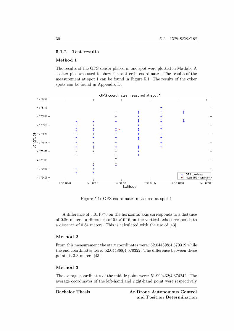
Method 1
The results of the GPS sensor placed in one spot were plotted in Matlab. Ascatter plot was used to show the scatter in coordinates. The results of themeasurement at spot 1 can be found in Figure 5.1. The results of the otherspots can be found in Appendix D.
Figure 5.1: GPS coordinates measured at spot 1
A difference of 5.0x10⁻⁶ on the horizontal axis corresponds to a distanceof 0.56 meters, a difference of 5.0x10⁻⁶ on the vertical axis corresponds toa distance of 0.34 meters. This is calculated with the use of [43].
Method 2
From this measurement the start coordinates were: 52.044898;4.570319 whilethe end coordinates were: 52.044868;4.570322. The difference between thesepoints is 3.3 meters [43].
Method 3
The average coordinates of the middle point were: 51.999432;4.374242. Theaverage coordinates of the left-hand and right-hand point were respectively
Bachelor Thesis Ar.Drone Autonomous Controland Position Determination
CHAPTER 5. TESTS 31
51.999506;4.374162 and 51.999366;4.374342. The distance between the mid-dle point and the left-hand point is 9.9 meter while the distance betweenthe middle point and the right-hand point is 10.0 meters [43].
Method 4
The result of test method 4 is shown in Figure 5.2. The starting point isindicated with a red arrow and the driving direction with arrows along thepath.
Figure 5.2: GPS coordinates measured while driving through Moerkapelle
5.1.3 Discussion
From section 5.1.2 and Appendix D it could be concluded that there is anaverage scatter of about 3 meters in both the longitude direction and thelatitude direction.
In Figure D.2 a lot of scatter was seen, this could be explained by thefact that this spot was 1 meter from a building so the building partly mighthave blocked the GPS signal. The conclusion from this is that near buildingsthe inaccuracy increases.
From section 5.1.2 it could be derived that moving and then returningto the same point has no influence on the accuracy.
In section 5.1.2 the distances that were measured by the GPS sensor andby hand were, except for a small margin, the same. It should be noted that
Ar.Drone Autonomous Controland Position Determination
Bachelor Thesis
32 5.2. BAROMETER
the average coordinates are used which gives better results than comparingjust three different coordinates. However the conclusion is that the GPSsensor is able to measure a difference of 10 meters very well.
In section 5.1.2 the GPS track roughly agreed with the driven track.There is some inaccuracy but this is within a margin of 5 meters. Thiscould partly be explained by the fact that the output was rounded to fouror five decimal places instead of six. The offsets could also be explained bythis rounding error. The rounding error had been corrected in the othertests however there was no time to repeat test method 4.
The promised accuracy of 1.8 meters ([38]) was not achieved. The de-sign specification of 2.0 meters accuracy (Appendix A) is also not achieved.However the specification in subsection 2.2.2 for GPS is achieved.
Part of the inaccuracy can be explained by the fact that all measure-ments were done in a not completely open area. The surrounding buildingsmay have been blocking the signal. As we saw in section 5.1.2, using anaverage coordinate gives better results. Therefore it is recommended to usean averaging filter before using the coordinates.
5.2 Barometer
5.2.1 Test methods
The barometer was tested both inside and outside. Two test methods wereperformed, both inside and outside.
The first method was to place the barometer at a flat surface and startlogging the altitude for two minutes. This was done at four different spotsoutside and two different spots inside.
The second method is related to the first method, logging was started atground level and then the barometer was moved to a higher level of whichthe height was measured. Inside the barometer was moved to a height of1.40 meter while outside the barometer was moved to a height of 1.50 meter.
5.2.2 Test results
Method 1
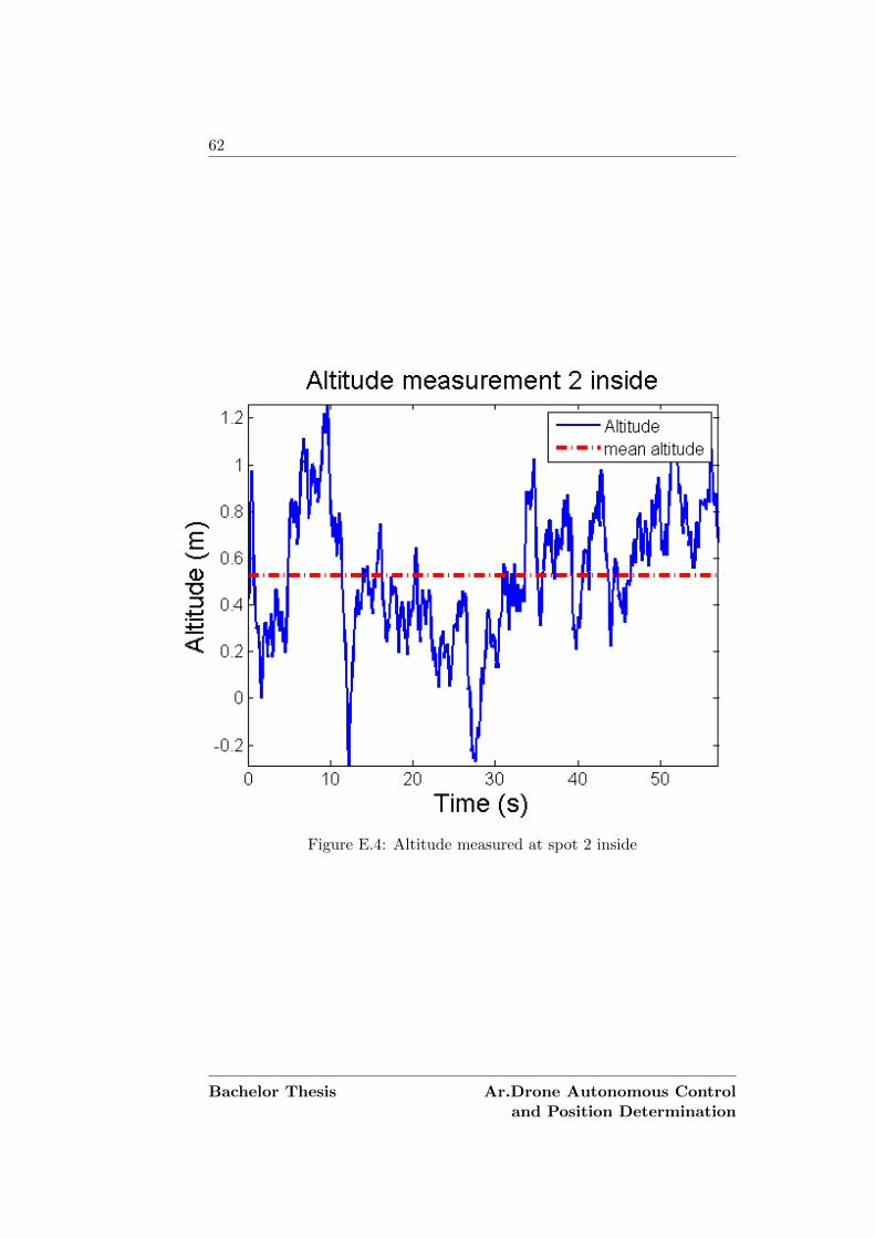
The results of the barometer placed at a flat surface are plotted in Matlab.The result of the measurement at the first spot inside and outside can befound in Figure 5.3. The results of the measurements at spots 2,3,4 outsideand spot 2 inside can be found in Appendix E.
Method 2
The results of the measurement which places the sensor at a certain heightcan be found in Figure 5.4.
Bachelor Thesis Ar.Drone Autonomous Controland Position Determination
CHAPTER 5. TESTS 33
(a) Altitude measured at spot 1 inside
(b) Altitude measured at spot 1 outside
Figure 5.3: Altitude measured while the barometer is at a flat surface
Ar.Drone Autonomous Controland Position Determination
Bachelor Thesis
34 5.2. BAROMETER
(a) Altitude difference measured inside
(b) Altitude difference measured outside
Figure 5.4: Altitude measured while the barometer is placed at a height
5.2.3 Discussion
From Figure 5.3, Figure 5.4 and Appendix E it was concluded that there is nodifference between inside and outside accuracy. The accuracy was rangingfrom 1.0 to 1.2 meters, the mean altitude was also off 1 to 7 decimetres.According to [40] the accuracy of the barometer is 0.2 hPa which is 1.7meters. So the accuracy of the altitude measurement (with the use of amoving average filter) corresponded to the specifications. The design rulefor the altitude was set at an accuracy of 1 meter. This design rule was notaccomplished in the static measurements.
Bachelor Thesis Ar.Drone Autonomous Controland Position Determination
CHAPTER 5. TESTS 35
Part of the inaccuracy can be explained by the fact that when the barom-eter is initialised, the first 10 values determine the reference value for thealtitude measurement. The altitude determination is based on this referencevalue so when this first 10 values do not give a good average value of thepressure on the ground, inaccuracy is introduced.
The accuracy of the altitude measurement can be improved by using another filter or by using a sensor that is more accurate. Another option isthe combination of a barometer and an INS to determine the altitude. TheINS can be used to correct the barometer measurements. A third optionis to use ultrasonic sensors when the UAV drops below a certain altitude,ultrasonic sensor can then be used for landing.
5.3 AR.Drone modelling
5.3.1 Test methods
To determine if the model of the AR.Drone’s behaviour is properly derived,four models had to be tested. These control variables were tested by givingan input and measuring the output. The p, r, g and y parameters indicatedin subsection 3.1.2 were derived and then the modelled output and actualoutput were compared.
The first output which was measured is the pitch. A desired pitch wasgiven and the pitch measured by the AR.Drone sensors was read out. Ex-actly the same test method was used for roll, gaz and yaw.
5.3.2 Test results
The parameters that were derived can be found in Table 5.1.
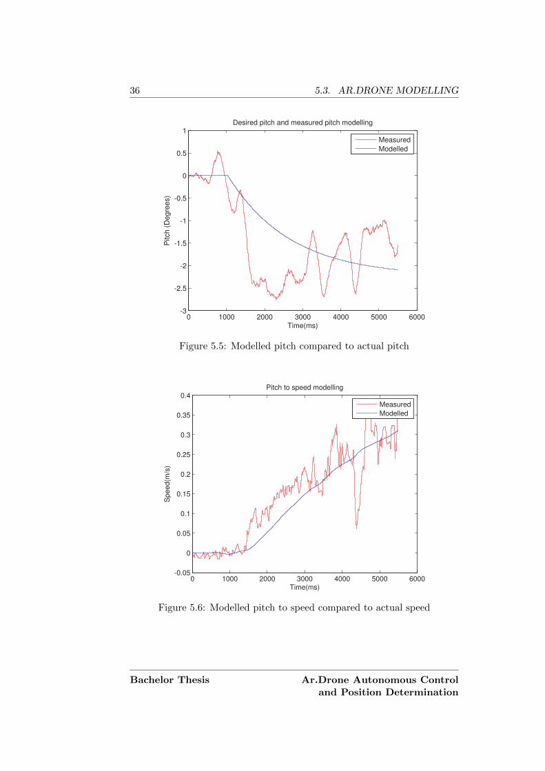
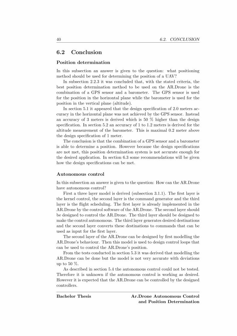
With the parameters of Table 5.1 the modelled values and actual valuescould be compared. In Figure 5.5 the modelled pitch and actual pitch canbe found. In Figure 5.6 the resulting modelled speed and actual speed isplotted. The modelled and real values of roll, gaz and yaw can be found inAppendix F
Ar.Drone Autonomous Controland Position Determination
Bachelor Thesis
36 5.3. AR.DRONE MODELLING
0 1000 2000 3000 4000 5000 6000-3
-2.5
-2
-1.5
-1
-0.5
0
0.5
1Desired pitch and measured pitch modelling
Time(ms)
Pitch (
Degre
es)
Measured
Modelled
Figure 5.5: Modelled pitch compared to actual pitch
0 1000 2000 3000 4000 5000 6000-0.05
0
0.05
0.1
0.15
0.2
0.25
0.3
0.35
0.4Pitch to speed modelling
Time(ms)
Speed(m
/s)
Measured
Modelled
Figure 5.6: Modelled pitch to speed compared to actual speed
Bachelor Thesis Ar.Drone Autonomous Controland Position Determination
CHAPTER 5. TESTS 37
5.3.3 Discussion
From the images in subsection 5.3.2 and Appendix F it can be seen thatpitch and roll are hard to model. The model has globally the same curve asthe real values but it differs at some points 50 %. The modelled speed thatis derived from the measured pitch, is following the curve well. However thespikes in the measurement are flattened in the model. The modelled gaz inFigure F.3 differs at least 50 % from the measured values. The modelledyaw however is differing less than 10 % most of the time.
The differences between the modelled values and measured values ofpitch, roll, gaz and yaw can partly be explained. The spikes in the mea-sured values can be caused by measurement errors in the sensors of theAR.Drone or by an instability of the AR.Drone. The measurement errorsand instability can be caused by a small breeze or a damage to the AR.Drone.
The differences between the modelled speed and actual speed can partlybe explained by the way in which the speed is measured by the AR.Drone.The AR.Drone measures it speed with accelerometers and the bottom cam-era [44]. Because the tests were performed on a reflecting floor, this mighthave influenced the speed detection. Due to the reflecting floor the AR.Dronewas even drifting slightly when it was in hovering mode.
Another factor that might have influenced the measurements is that thehull of the AR.Drone was modified. Because the first layer controller ofthe AR.Drone is designed for the unmodified version of the AR.Drone, thecontroller is acting different.
5.4 AR.Drone control loops
5.4.1 Test methods
While in section 5.3 the model was tested, in this section the software thatis controlling the AR.Drone has been tested.
The software was tested by letting the AR.Drone fly to destinations.This was the best method to make sure the software was doing what itshould do. When the AR.Drone had reached its destination the relativeposition to its departure position was measured.
5.4.2 Test results
Due to bugs in the controller loop implementation the velocity informationfrom the AR.Drone was not received correctly. This resulted in unstablecontrollers. Therefore the control loops could not be tested in the giventime frame.
Ar.Drone Autonomous Controland Position Determination
Bachelor Thesis
38 5.4. AR.DRONE CONTROL LOOPS
Bachelor Thesis Ar.Drone Autonomous Controland Position Determination
Chapter 6
Conclusion
This chapter will start with summarizing the goal of this thesis (section 6.1).Then some conclusions will be drawn from the research performed in chap-ter 2 and chapter 3 combined with the test results of chapter 5 (section 6.2).Next some recommendations, based on the conclusion, will be given (sec-tion 6.3). Finally suggestions for future work will be given (section 6.4).The future work section indicates what should be done, in relation to thesubjects of this thesis, for the final system and what can be done to improvethe current system.
6.1 Goal
For an object detection and tracking system for a UAV, a position deter-mination system should be developed. This position data is used by thedetection and tracking system to determine the drone’s position, calculatethe position of the object and control the UAV. Furthermore the detec-tion and tracking system should be tested on a Parrot AR.Drone. ThisAR.Drone should therefore be enabled to fly autonomous. To design a posi-tion determination system and an autonomous control, two main questionswere formulated:
1. What positioning method should be used for determining an positionof a UAV?
2. How can the AR.Drone have autonomous control?
39
40 6.2. CONCLUSION
6.2 Conclusion
Position determination
In this subsection an answer is given to the question: what positioningmethod should be used for determining the position of a UAV?
In subsection 2.2.3 it was concluded that, with the stated criteria, thebest position determination method to be used on the AR.Drone is thecombination of a GPS sensor and a barometer. The GPS sensor is usedfor the position in the horizontal plane while the barometer is used for theposition in the vertical plane (altitude).
In section 5.1 it appeared that the design specification of 2.0 meters ac-curacy in the horizontal plane was not achieved by the GPS sensor. Insteadan accuracy of 3 meters is derived which is 50 % higher than the designspecification. In section 5.2 an accuracy of 1 to 1.2 meters is derived for thealtitude measurement of the barometer. This is maximal 0.2 meter abovethe design specification of 1 meter.
The conclusion is that the combination of a GPS sensor and a barometeris able to determine a position. However because the design specificationsare not met, this position determination system is not accurate enough forthe desired application. In section 6.3 some recommendations will be givenhow the design specifications can be met.
Autonomous control
In this subsection an answer is given to the question: How can the AR.Dronehave autonomous control?
First a three layer model is derived (subsection 3.1.1). The first layer isthe kernel control, the second layer is the command generator and the thirdlayer is the flight scheduling. The first layer is already implemented in theAR.Drone by the control software of the AR.Drone. The second layer shouldbe designed to control the AR.Drone. The third layer should be designed tomake the control autonomous. The third layer generates desired destinationsand the second layer converts these destinations to commands that can beused as input for the first layer.
The second layer of the AR.Drone can be designed by first modelling theAR.Drone’s behaviour. Then this model is used to design control loops thatcan be used to control the AR.Drone’s position.
From the tests conducted in section 5.3 it was derived that modelling theAR.Drone can be done but the model is not very accurate with deviationsup to 50 %.
As described in section 5.4 the autonomous control could not be tested.Therefore it is unknown if the autonomous control is working as desired.However it is expected that the AR.Drone can be controlled by the designedcontrollers.
Bachelor Thesis Ar.Drone Autonomous Controland Position Determination
CHAPTER 6. CONCLUSION 41
The conclusion is that an AR.Drone can have autonomous control bydesigning a command generator layer and a flight scheduling layer. Thecommand generator can be designed by first modelling the AR.Drone’s be-haviour and designing appropriate control loops subsequently.
6.3 Recommendations
Position determination
To improve the accuracy of the used position determination method, thereare a few recommendations.
To improve the accuracy of the GPS sensor a Kalman filter can be used.Due to limited time this filter could not be implemented a quick literaturesurvey however showed that a Kalman filter would be applicable.
To improve the accuracy of the barometer, an other filter than the cur-rent moving average filter can be used. The determination of the referencevalues should be improved to improve the determination of the altitude.This can be done by taking a longer period to determine the reference co-ordinates.
However when an of-the-shelf autopilot is used for the UAV it is recom-mended to use the position sensors that are required by the autopilot.
To gain the best position determination result, a combination of an INS,a GPS sensor and a barometer is recommended. The INS can be used tocorrect the values of the GPS sensor and barometer. The INS can alsoprovide position data when there is no GPS signal available.
Autonomous control
To improve the autonomous control, there are a few recommendations.To improve the accuracy of the modelled behaviour an unmodified AR.Drone
should be used or the first layer of the AR.Drone should be adjusted. Maybethe accuracy of the model can also be improved by doing the tests on a non-reflective, textured floor. This will improve the speed measurements of theAR.Drone.
As the controller gains are calculated based on the modelled behaviour ofthe AR.Drone, their values could be improved if a better model is available.
Ar.Drone Autonomous Controland Position Determination
Bachelor Thesis
42 6.4. FUTURE WORK
6.4 Future work
Because the limited time to implement, test and improve all proposed meth-ods, there are some points whereon further work should be done. Thesepoints are listed below in order of priority. Some of these points are focussedon the object detection and tracking system while others are focussed on theAR.Drone as a testing platform.
I Debugging the AR.Drone control softwareAs indicated earlier, there was no time left to debug the software andtherefore the control loops could not be tested.
II Testing of the position determination method on a UAVDue to time constraints, it was not possible to test the position deter-mination method on a UAV. To fully test the position determinationmethod, it should be tested on a UAV.
III Improvement of the position determinationAs indicated in section 6.3 the position determination can be improvedin several ways. It is suggested to use an INS to improve the accuracy.The inaccuracy should be as low as possible because the position iscrucial for the determination of the object and for safety reasons.
IV Improvement of the AR.Drone model and controllerFor the use of the AR.Drone as a testing platform the model of theAR.Drone should be improved. Also other methods could be used todetermine the control loops.
V Implementation of an autopilotFor the final UAV an autopilot should be designed or an existing au-topilot should be adjusted to control the UAV. Because in the currentsystem the autopilot of the AR.Drone is used.
VI Implementation of absolute coordinatesThe AR.Drone control model can be adjusted to take the current po-sition and the desired position and calculate the relative coordinates.When this is implemented, it is possible to give the desired GPS co-ordinates as input and the AR.Drone will fly to these coordinates. Toimplement this, it is recommended to implement a compass becausethe bearing of the AR.Drone should be known to calculate the relativecoordinates.
Bachelor Thesis Ar.Drone Autonomous Controland Position Determination
Bibliography
[1] Y. Naidoo, R. Stopforth, and G. Bright, “Development of an UAV forsearch & rescue applications,” in AFRICON, 2011, sept. 2011, pp. 1–6.
[2] J. Sullivan, “Revolution or evolution? The rise of the UAVs,” in Tech-nology and Society, 2005. Weapons and Wires: Prevention and Safetyin a Time of Fear. ISTAS 2005. Proceedings. 2005 International Sym-posium on, june 2005, pp. 94 – 101.
[3] J. Leyssens, “GNSS positioning for UAV Applications,” http-wwwgnssus, 2009. [Online]. Available: http://www.gnss.us/uploads/GNSS positioning for UAV Applications Leyssens.pdf
[4] G. A. Ch. Kreye, B. Eissfeller, “Architectures of GNSS/INS Integra-tions -Theoretical Approach and Practical Tests,” 2004.
[5] C.-J. Sun, C.-W. Hung, W.-C. Huang, and C. Lin, “Implementation ofGPS/INS navigation system using low-cost MEMS sensors,” in Indus-trial Electronics and Applications (ICIEA), 2010 the 5th IEEE Confer-ence on, june 2010, pp. 1588 –1592.
[6] X. Lei, J. Liang, S. Wang, and Tianmiao, “An integrated navigationsystem for a small UAV using low-cost sensors,” in Information andAutomation, 2008. ICIA 2008. International Conference on, june 2008,pp. 765 –769.
[7] Y. Jiong, Z. Lei, D. Jiangping, S. Rong, and W. Jianyu, “GPS/SIN-S/BARO Integrated Navigation System for UAV,” in Information Tech-nology and Applications (IFITA), 2010 International Forum on, vol. 3,july 2010, pp. 19 –25.
[8] B. Mohr and D. Fitzpatrick, “Micro air vehicle navigation system,”Aerospace and Electronic Systems Magazine, IEEE, vol. 23, no. 4, pp.19 –24, april 2008.
[9] Z. Tao and W. Lei, “SINS and GPS Integrated Navigation System ofa Small Unmanned Aerial Vehicle,” in Future BioMedical Information
Engineering, 2008. FBIE ’08. International Seminar on, dec. 2008, pp.465 –468.
[10] L. Wang, S.-C. Hsieh, E.-W. Hsueh, F.-B. Hsaio, and K.-Y. Huang,“Complete pose determination for low altitude unmanned aerial vehicleusing stereo vision,” in Intelligent Robots and Systems, 2005. (IROS2005). 2005 IEEE/RSJ International Conference on, aug. 2005, pp.108 – 113.
[11] R. Moore, S. Thurrowgood, D. Bland, D. Soccol, and M. Srinivasan,“UAV altitude and attitude stabilisation using a coaxial stereo visionsystem,” in Robotics and Automation (ICRA), 2010 IEEE InternationalConference on, may 2010, pp. 29 –34.
[12] Z. Zhu, S. Xiong, and Z. Zhou, “A micro barometric altimeter withapplications in altitude-holding flight control for MAVs,” in Instru-mentation and Measurement Technology Conference, 2004. IMTC 04.Proceedings of the 21st IEEE, vol. 2, may 2004, pp. 1039 – 1041 Vol.2.
[13] T. Puls and A. Hein, “Outdoor position estimation and autonomouslanding algorithm for quadrocopters using a wireless sensor network,”in Advanced Intelligent Mechatronics (AIM), 2010 IEEE/ASME Inter-national Conference on, july 2010, pp. 285 –290.
[14] H.-C. Lee, “Simple landing distance measurement with circular markbetween aircraft and runway,” in Digital Avionics Systems Conference,2009. DASC ’09. IEEE/AIAA 28th, oct. 2009, pp. 5.A.5–1 –5.A.5–8.
[15] Parrot SA, “AR.Drone Parrot,” [Online; available at: http://ardrone.parrot.com/parrot-ar-drone/usa], accessed on May 11, 2012.
[16] T. Krajnık, V. Vonasek, D. Fiser, and J. Faigl, “AR-Drone asa Platform for Robotic Research and Education,” in Research andEducation in Robotics - EUROBOT 2011, ser. Communications inComputer and Information Science, D. Obdrzalek and A. Gottscheber,Eds. Springer Berlin Heidelberg, 2011, vol. 161, pp. 172–186,10.1007/978-3-642-21975-7 16. [Online]. Available: http://dx.doi.org/10.1007/978-3-642-21975-7 16
[17] K. Higuchi, T. Shimada, and J. Rekimoto, “Flying sports assistant:external visual imagery representation for sports training,” inProceedings of the 2nd Augmented Human International Conference,ser. AH ’11. New York, NY, USA: ACM, 2011, pp. 7:1–7:4. [Online].Available: http://doi.acm.org/10.1145/1959826.1959833
[18] C. Bills, J. Chen, and A. Saxena, “Autonomous MAV flight in indoorenvironments using single image perspective cues,” in Robotics and Au-
Bachelor Thesis Ar.Drone Autonomous Controland Position Determination
tomation (ICRA), 2011 IEEE International Conference on, may 2011,pp. 5776 –5783.
[19] W. S. Sharlin, Ehud Ng, “Collocated Interaction with Flying Robots,”Tech. Rep., 2011.
[20] Parrot SA, “A technological first,” [Online; available at: http://ardrone.parrot.com/parrot-ar-drone/en/technologies], accessed on May17, 2012.
[21] U. S. DoD, “Global positioning system standard positioningservice performance standard.” Distribution, no. September, p. 160,2008. [Online]. Available: http://www.navcen.uscg.gov/gps/geninfo/2001SPSPerformanceStandardFINAL.pdf
[22] NIS GLONASS, “GLONASS Technical Description,” [Online; avail-able at: http://www.nis-glonass.ru/en/glonass/technical descript/],accessed on May 18, 2012.
[23] European Space Agency, “What is Galileo,” [Online; available at: http://www.esa.int/esaNA/galileo.html], accessed on May 18, 2012.
[24] P. Groves, Principles of GNSS, inertial, and multi-sensor integratednavigation systems, ser. GNSS technology and applications series.Artech House, 2008.
[25] I. Mohamad, M. Ali, and M. Ismail, “Availability, reliability and accu-racy of gps signal in bandar baru bangi for the determination of vehicleposition and speed,” in Space Science and Communication, 2009. Icon-Space 2009. International Conference on, oct. 2009, pp. 224 –229.
[26] Y. Liu and S. Tian, “Vertical positioning technologies and its applica-tion of pseudolites augmentation,” in Wireless Communications, Net-working and Mobile Computing, 2008. WiCOM ’08. 4th InternationalConference on, oct. 2008, pp. 1 –3.
[27] G. Elkaim, M. Lizarraga, and L. Pederseny, “Comparison of low-costgps/ins sensors for autonomous vehicle applications,” in Position, Loca-tion and Navigation Symposium, 2008 IEEE/ION, may 2008, pp. 1133–1144.
[28] L. Sahawneh and M. Jarrah, “Development and calibration of low costMEMS IMU for UAV applications,” in Mechatronics and Its Applica-tions, 2008. ISMA 2008. 5th International Symposium on, may 2008,pp. 1 –9.
[29] H. Nakanishi, S. Kanata, and T. Sawaragi, “Measurement model ofbarometer in ground effect of unmanned helicopter and its application
Ar.Drone Autonomous Controland Position Determination
to estimate terrain clearance,” in Safety, Security, and Rescue Robotics(SSRR), 2011 IEEE International Symposium on, nov. 2011, pp. 232–237.
[30] R. Moore, S. Thurrowgood, D. Bland, D. Soccol, and M. Srinivasan,“A stereo vision system for uav guidance,” in Intelligent Robots andSystems, 2009. IROS 2009. IEEE/RSJ International Conference on,oct. 2009, pp. 3386 –3391.
[31] Y. chi Liu and Q. hai Dai, “Vision aided unmanned aerial vehicle au-tonomy: An overview,” in Image and Signal Processing (CISP), 20103rd International Congress on, vol. 1, oct. 2010, pp. 417 –421.
[32] K. Peng, G. Cai, B. M. Chen, M. Dong, K. Y. Lum, andT. H. Lee, “Design and implementation of an autonomousflight control law for a uav helicopter,” Automatica, vol. 45,no. 10, pp. 2333 – 2338, 2009. [Online]. Available: http://www.sciencedirect.com/science/article/pii/S0005109809003082
[33] J. T. Zimmerling and H. A. R. Homulle, “Intelligent uav camera systemobject searching and tracking,” Bachelor Thesis, Delft University ofTechnology, June 2012.
[34] S. L. van Berkel and X. F. van Kooten, “Ground station user interfaceand data link for unmanned aerial vehicles,” Bachelor Thesis, DelftUniversity of Technology, June 2012.
[35] Beagleboard.org, “Home,” [Online; available at: http://www.beagleboard.org/], accessed on May 31, 2012.
[36] Raspberry Pi Foundation, “Raspberry Pi,” [Online; available at: http://www.raspberrypi.org/], accessed on May 31, 2012.
[37] W. E. Hong, J.-S. Lee, L. Rai, and S. J. Kang, “Embedded real-timesoftware architecture for unmanned autonomous helicopters,” Journalof Semiconductor Technology and Science, 2005.
[42] G. Franklin, J. Powell, and A. Emami-Naeini, Feedback Control of Dy-namic Systems. Pearson, 2009.
[43] Moveable Type Scripts, “Calculate distance, bearing and more be-tween Latitude/Longitude points,” [Online; available at: http://www.movable-type.co.uk/scripts/latlong.html], accessed on June 4, 2012.
[44] P.-J. Bristeau, F. Callou, D. Vissiere, and N. Petit, “The navigationand control technology inside the ar.drone micro uav,” in 18th IFACWorld Congress, Milano, Italy, 2011, pp. 1477–1484.
Ar.Drone Autonomous Controland Position Determination
Bachelor Thesis Ar.Drone Autonomous Controland Position Determination
Appendix A
Design Brief
On the following pages the design brief of the final product can be found.The final product is a completely working object detection and trackingsystem.
49
Design Brief — UAV Systems —
1. IntroductionFor this Bachelor Thesis Project within the curriculum of Electrical Engineering at the department of EEMCSof Delft University of Technology, a system will be designed for implementation on an Unmanned Aerial Ve-hicle (UAV). This system will be a combination of hardware and software. It will focus on the professionalmarket and, with minor modifications, is to be used in the UAV Competition organized by Thijs Durieux andJohan Melis. This document will specify project requirements and design constraints.
2. Requirements derived from the intended use2.1. The system must flexible to the extent that it can be implemented on both so-called ‘quadro-copters’1
and fixed-wing UAVs. A detailed definition of ’flexible’:2.1.1. The system must be able to function properly on a fixed-wing UAV with a velocity of 100 km/h.2.1.2. The battery power, the number of available I/O ports and the available processing power must be
sufficient to allow for an extension of the system with a second camera and additional sensors. Thisrequirement is related to the future possibility of tracking other airborne vehicles.
2.2. The system must be capable of detecting a ground-based moving vehicle from the air.2.3. The system must be capable of tracking (i.e., following) the ground-based vehicle at a distance of no
more than 50 m.2.4. The velocity of the detected vehicle may not exceed 55 km/h.2.5. The system must be capable of taking a photograph of the detected ground-based vehicle.2.6. The system must be capable of transmitting the photograph to a ground station.2.7. The system must be able to determine its position (x and y) with a resolution of 2 m.2.8. The system must be able to determine its height (i.e., z) with a resolution of 1 m.2.9. The system need not autonomously control a UAV.
2.10. The system need not withstand rain or extreme humidity.2.11. The mass of the system – including camera and battery – may not exceed 500 g.2.12. The system must function at least 1 hour with its own battery.2.13. The system must be delivered and documented in such a way that work can be continued by people not
regularly affiliated to the project and our project team.2.14. A (scaled) demonstrator must be delivered, consisting of a Parrot AR.Drone that is capable of tracking
an RC model car and transmitting an aerial photograph of this car to a base station. The control andposition signals transmitted by the UAV must be visualized in a graphical user interface (GUI) on theground station.
3. Requirements derived from the (ecological) situation of the system in its surroundings3.1. The system must comply with all legislation concerning radio wave transmission.3.2. The altitude of the system may not exceed 70 m.3.3. The system must be able to communicate with its ground station in all possible geometrical positions.3.4. The system must be able to communicate with its ground station over a range of 1000 m.3.5. The system is to be built from standardized components and shall therefore comply with environmental
standards such as RoHS.3.5.1. The lifetime of the system will be determined by the lifetime of the components.3.5.2. Requirements with respect to recycling and disposal are determined by the components of the system.
1Helicopter-like aircraft with four horizontal rotors, often arranged in a square layout.
Delft University of Technology, Department of EEMCS 1
Design Brief — UAV Systems —
4. Requirements concerning the system as such4.1. The system must generate and transmit a signal if the battery power drops below a predetermined
threshold value.4.2. The system must be able to cope with flight vibrations to the extent that its functionality is not influenced
during flight.4.3. The system must send a signal to the autopilot if the connection between the system and its ground
station is lost for more than t seconds. This threshold value t must be set to the desired value digitally.4.4. The system must send signals to the autopilot protocol or bus (to be determined) concerning its position
and the (estimated) position of the tracked vehicle.4.5. The data link between the system and the ground station must be suitable for transmitting autopilot
signals with a maximum bandwidth of 2 MHz.
MoSCoW model draft
Must have� All points mentioned in the design brief.
Should have� Possibility of detecting an airborne vehicle (e.g., another UAV).� Possibility of tracking the detected airborne vehicle.
Could have� Fully functional built-in autopilot.� Possibility of defining geographical operating boundaries of the UAV.
Would have (would be)� A fully autonomous fixed-wing UAV that meets the demands of Thijs Durieux and Johan Melis.
Delft University of Technology, Department of EEMCS 2
52
Bachelor Thesis Ar.Drone Autonomous Controland Position Determination
Appendix B
Functional block diagram
In the figure below a functional block diagram of the whole system can befound. At the left the inputs of the system can be found while at the rightthe outputs can be found. In the middle the processing of the input to theoutput is showed.
53
54
Bachelor Thesis Ar.Drone Autonomous Controland Position Determination
hhmmss.ss = UTC of position fixA = Data statusllll.ll = latitude of fixa = North or Southyyyyy.yy = longitude of fixb = East or Wests.s = speed over ground in knotsd.d = track made good in degrees trueddmmyy = UT datex.x = magnetic variation in degreesc = East or Westhh = checksum
55
56
Bachelor Thesis Ar.Drone Autonomous Controland Position Determination
Appendix D
GPS fixed spotmeasurements
Figure D.1: GPS coordinates measured at spot 2
57
58
Figure D.2: GPS coordinates measured at spot 3
Figure D.3: GPS coordinates measured at spot 4
Bachelor Thesis Ar.Drone Autonomous Controland Position Determination
Appendix E
Barometer flat surfacemeasurements
Figure E.1: Altitude measured at spot 2 outside
59
60
Figure E.2: Altitude measured at spot 3 outside
Bachelor Thesis Ar.Drone Autonomous Controland Position Determination
APPENDIX E. BAROMETER FLAT SURFACE MEASUREMENTS 61
Figure E.3: Altitude measured at spot 4 outside
Ar.Drone Autonomous Controland Position Determination
Bachelor Thesis
62
Figure E.4: Altitude measured at spot 2 inside
Bachelor Thesis Ar.Drone Autonomous Controland Position Determination
Appendix F
Behaviour modelmeasurements
In this appendix the modelled and measured parameters are plotted.
0 2000 4000 6000 8000 10000-3.5
-3
-2.5
-2
-1.5
-1
-0.5
0
0.5Desired roll to measured roll modelling
Time(ms)
Ro
ll(D
eg
ree
s)
Measured
Modelled
Figure F.1: Modelled roll compared to actual roll
63
64
0 2000 4000 6000 8000 10000-0.7
-0.6
-0.5
-0.4
-0.3
-0.2
-0.1
0
0.1Roll to speed modelling
Time(ms)
Sp
ee
d(m
/s)
Measured
Modelled
Figure F.2: Modelled roll to speed compared to actual speed
0 1000 2000 3000 4000 5000 6000 7000-2
-1
0
1
2
3
4
5
6
7Desired vertical speed to measured speed modelling
Time(ms)
Ve
rtic
al S
pe
ed
(m/s
)
Measured
Modelled
Figure F.3: Modelled gaz compared to actual gaz
Bachelor Thesis Ar.Drone Autonomous Controland Position Determination
APPENDIX F. BEHAVIOUR MODEL MEASUREMENTS 65
0 1000 2000 3000 4000 5000 6000-4
-3.5
-3
-2.5
-2
-1.5
-1
-0.5
0
0.5Desired yaw rate to measured yaw rate modelling
Time(ms)
Yaw
rate
(Degre
es/s
)
Measured
Modelled
Figure F.4: Modelled yaw compared to actual yaw
Ar.Drone Autonomous Controland Position Determination