09/2005 - Art. Nr. 13 019 526A Operating instructions For the authorised specialist Gas burners ......................................... 2-31 VECTRON G 05.700 MODULO VECTRON G 05.1000 MODULO Ersatzteilliste Spare parts list Pièces de rechange Wisselstukkenlijst Elektro- und Hydraulikschema Electric and hydraulic diagrams Schémas électr. et hydraulique Elektr. en hydraulische schema Art. Nr. 13 018 839 EN } Art. Nr. 13 019 525 }
Transcript
09/2005 - Art. Nr. 13 019 526A
Operating instructionsFor the authorised specialistGas burners .........................................2-31
VECTRON G 05.700 MODULOVECTRON G 05.1000 MODULO
ErsatzteillisteSpare parts listPièces de rechangeWisselstukkenlijst
Elektro- und HydraulikschemaElectric and hydraulic diagramsSchémas électr. et hydrauliqueElektr. en hydraulische schema
Overview of combustion control unitMPA22Function description ..........................11Display and operating unit ................12Programme structure .......................13
Start-upDefault settings..................................18Burner head, gas and airpressure switch settings,gas pressure regulator ......................19Checks before start-up......................20Control unit auto-test.........................20Adjustment mode .........................21-25
Access....................................21Parameters menu..............21-22Cold adjustment menu ...........23Hot adjustment menu........24-25
We, CEB, of18, rue des Bûchillons Ville-la-GrandF-74106 ANNEMASSE Cedexdeclare under our sole responsibilitythat the products
VECTRON G 05.700 MODULOVECTRON G 05.1000 MODULO
conform to the following standards
EN 60335EN 50081EN 50082EN 676
In accordance with the stipulations of theEuropean Directives
90 / 396 / EEC Gas device guidelines89 / 336 / EEC EMC directive73 / 23 / EEC Low voltage
directive92 / 42 / EEC Working efficiency
directive
these products bear the CE marking
Ville-la-Grand, 01 January 2005J. HAEP
Overview
309/2005 - Art. Nr. 13 019 526A
Overview
Important notes
Important instructionsThe G 05.700/1000 MODULO burnersare designed to burn natural gas orpropane gas in category II 2 ELL 3P.The special construction of the burnerhead with internal recirculation ofexhaust gases means that combustionis very low in nitric oxide when burningnatural gas.The design and function of the burnersmeet standard EN676.Assembly, start-up and maintenancemust be carried out only by authorisedspecialists and all applicable guidelinesand regulations complied with.Gas pipes and fittings must likewise beinstalled in compliance with allapplicable guidelines and regulations(e.g. DVGW-TRGI 1986/96; TRF 1988;DIN 4756).Only DVGW-tested and -approvedsealing materials should be used.Connections should be leak-testedusing non-corrosive foam-producingmaterials or similar.Gas piping should be vented beforestart-up. Under no circumstancesshould venting be carried out over thefurnace.Repair work to switches, limiters,control and safety units and otherindividual items of safety equipmentmust be carried out by the relevantmanufacturer or his representatives.The replacement of original parts mustbe carried out by specialist staff.
Basic regulationsThe following standards should beobserved in order to ensure safe,environmentally sound andenergy-saving operation:
DIN 4705Calculation of flue dimensionsEN 676Forced-draught gas burnersEN 226Connection to heating systems ofvaporising-fuel-oil and forced-draughtgas burnersVDE 0116Electrical equipment for furnacesystemsEN 60335-1Safety of electrical equipment fordomestic use and similar purposesVDE 0722Electrical Equipment for non-electricallypowered heating devices.
Installation locationThe burner must not be used in roomswith aggressive vapours (e.g. hairspray, perchlorethelen, carbontetrachloride), high levels of dust orhigh air humidity (e.g. washhouses).An air inlet must be present:– up to 50 kW: 150 cm²– for every further kW: +2 cm²Variations may arise as a result of localregulations.
The guarantee does not coverdamage resulting from:� Inappropriate use� Incorrect installation and/or initial
start-up on the part of the buyer orany third party, including the fittingof non-original parts.
� Operation of the system atexcessive pressure.
Final delivery and instructions for useThe combustion system manufacturermust supply the operator with operatingand maintenance instructions on orbefore final delivery. These instructionsshould be displayed in a prominentlocation at the point of installation of theheating unit, and should include theaddress and telephone number of thenearest customer service centre.
Notes for the operatorThe system should be inspected by aspecialist at least once a year. It isadvisable to enter into a maintenancecontract in order to ensure trouble-freerunning.
EN
4 09/2005 - Art. Nr. 13 019 526A
Overview
Description of burner
Burner descriptionThe G 05.700/1000 MODULO burnersare low emission, modulating gasburners with a monoblock typeelectronic connection. They are suitablefor use with all heat generators inaccordance with DIN 4702/EN 303within the respective performance range.
Scope of deliveryThe burner is supplied in threepackaging units:� Burner housing with operating
� Gas valve assembly with gas throttlemodule, DMV gas valve with built-inpocket filter or with external filter,connection parts, screws, seals.
Optional accessories:– Separate air intake box– Air intake silencer– Gas stop valve– Thermal safety cut-out valve– Compensator– Power regulator– Potentiometer– Test burner– Pressure gauge
A1 Combustion control unitA4 Display and operating unitB10 Ionisation bridgeF6 Air pressure switchF12 Protective motor relayK1 Motor contactorM1 Burner motorT1 Ignition transformer (concealed)Y10 Servomotor air flap7 Control panel8 Blast tube13 Burner cover113 Air box
509/2005 - Art. Nr. 13 019 526A
Overview
Technical DataPower graphs
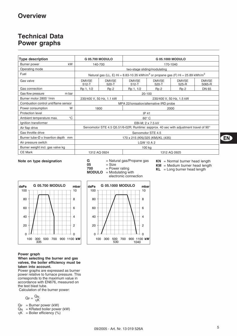
Power graphWhen selecting the burner and gasvalves, the boiler efficiency must betaken into account.Power graphs are expressed as burnerpower relative to furnace pressure. Thiscorresponds to the maximum value inaccordance with EN676, measured onthe test blast tube.Calculation of the burner power:
QF = Burner power (kW)QN = KRated boiler power (kW)�K = Boiler efficiency (%)
QNQF =�K
Type description G 05.700 MODULO G 05.1000 MODULO
Burner power kW 140-700 170-1040
Operating mode two-stage sliding/modulating
Fuel Natural gas (LL, E) Hi = 8.83-10.35 kWh/m3 or propane gas (F) Hi = 25.89 kWh/m3
Gas valve DMVSE512-T
DMVSE520-T
DMVSE512-T
DMVSE520-T
DMVSE525-R
DMVSE5065-R
Gas connection Rp 1, 1/2 Rp 2 Rp 1, 1/2 Rp 2 Rp 2 DN 65
Combustion control unit/flame sensor MPA 22/ionisation/alternative IRD probe
Power consumption W 1800 2000
Protection level IP 41
Ambient temperature max. °C 60° C
Ignition transformer EBI-M; 2 x 7.5 kV
Air flap drive Servomotor STE 4.5 Q5.51/6-02R; Runtime: aspprox. 40 sec with adjustment travel of 90°
Gas throttle drive Servomotor STE 4.5
Burner tube-Ø x Insertion depth mm 170 x 215 (KN)/325 (KM)/KL (435)
Air pressure switch LGW 10 A 2
Burner weight incl. gas valve kg 100 kg
CE Mark 1312 AQ 0924 1312 AQ 0925
Note on type designation G = Natural gas/Propane gas05 = Size700 = Power ratingMODULO = Modulating with
electronic connection
KN = Normal burner head lengthKM = Medium burner head lengthKL = Long burner head length
daPa mbar
kW335
0
20
40
60
80
100
100 300 500 700 900 1100
0
2
4
6
8
10daPa mbar
kW530 1040
0
20
40
60
80
100
100 300 500 700 900 1100
0
2
4
6
8
10
G 05.700 MODULO G 05.1000 MODULO
EN
6 09/2005 - Art. Nr. 13 019 526A
Overview
Burnerpower
(kW)
DMV512-TRp1,1/2
DMV520-TRp 2
DMV512-TRp1,1/2
DMV520-TRp 2
DMV512-TRp1,1/2
Natural gas E Hi = 10.365 kWh/m3 Natural gas LL Hi = 8.83 kWh/m3 Propane gasHi=25.89kWh/m³
Gas pressure loss (from gas valve inlet)
550 16 15 17 15 15
600 19 15 21 16 15
650 22 18 24 19 17
700 26 21 28 22 20
Gas valve selectionThe gas pressure loss specified in thetable is to be added on to the combus-tion chamber pressure in mbar.
N.B.:The calculated gas flow pressure is tobe complied with at the gas valve inlet.To calculate the gas flow pressurerequired at the transfer station, theresistance of the burner supply conduitincluding valves (ball valve, TAS, addi-tional filter or counter) must also betaken into account.
Example (for Burner G 05.1000 MODULO):
� System data:– Gas type: natural gas E– Gas flow pressure: 20 mbar (N.B.: at gas valve inlet)– Required burner power: 700 kW– Combustion chamber pressure with boiler rated load: 2.5 mbar� Condition: working point must be within the burner’s permissible field of work.� Selected gas valve: DMV 520-T� Checking the selection:– Gas pressure loss (from table): 17 mbar– Combustion chamber pressure: 2.5 mbar
Total 19.5 mbar– Hence: Gas flow pressure 20 mbar >19.5 mbar �Selection of DMV520-T correct.
Burnerpower
(kW)
DMV512-TRp1,1/2
DMV520-TRp 2
DMV525-RRp 2
DMV5065-RDN65
DMV520-TRp 2
DMV525-RRp 2
DMV5065-RDN65
DMV512-TRp1,1/2
Natural gas E Hi = 10.365 kWh/m³ Natural gas LL Hi = 8.83 kWh/m³ Propane gasHi=25.89kWh/m³
Gas pressure loss (from gas valve inlet)
550 17 15 15 15 15 15 15 15
600 20 15 15 15 17 15 15 15
650 23 15 15 15 20 17 17 16
700 27 17 15 15 24 20 20 18
750 31 20 18 18 27 23 23 21
800 35 23 20 20 31 26 26 24
850 40 26 23 23 35 29 29 27
900 44 29 25 25 39 33 33 30
950 49 32 28 28 44 37 37 34
1000 55 36 31 31 48 41 41 38
1
G 05.700 MODULO
G 05.1000 MODULO
709/2005 - Art. Nr. 13 019 526A
Space requirementsThere should be a space of no lessthan 0.60 m on each side of the burnerfor maintenance purposes.
Gas valve assemblyThe valve assembly can be fitted on theleft or the right.
Overview
Dimensional drawings and measurementsG 05.700/1000 MODULOWith DMV SE gas valve
KN
KM
KL
KN
KM
KL
KN
KM
KL
EN
8 09/2005 - Art. Nr. 13 019 526A
Overview
Gas valve assembly
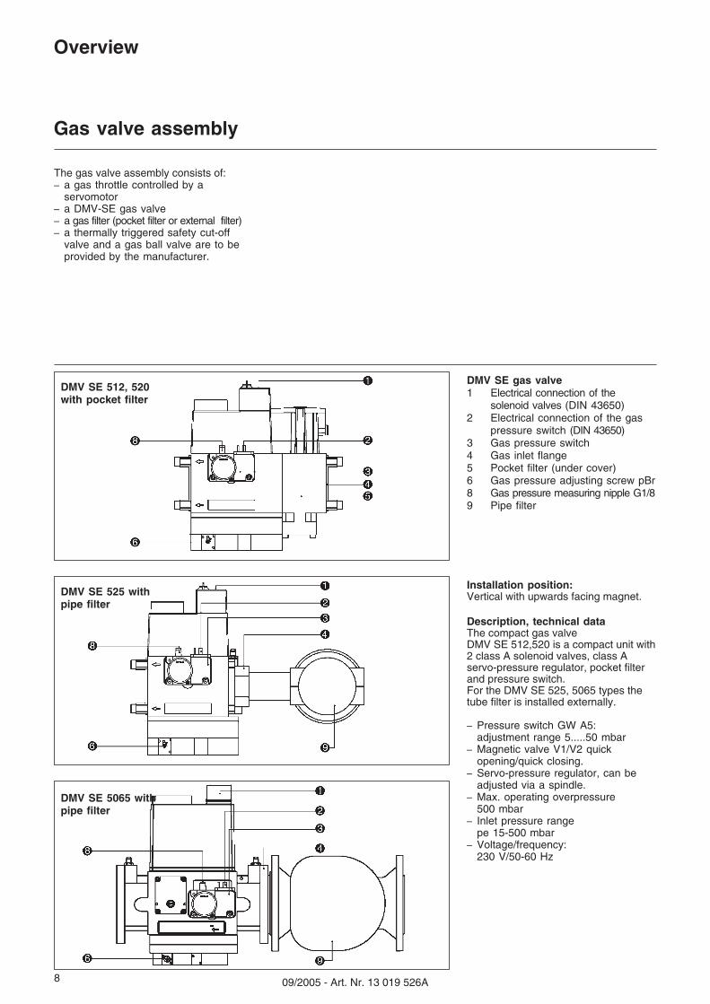
Installation position:Vertical with upwards facing magnet.
Description, technical dataThe compact gas valveDMV SE 512,520 is a compact unit with2 class A solenoid valves, class Aservo-pressure regulator, pocket filterand pressure switch.For the DMV SE 525, 5065 types thetube filter is installed externally.
– Pressure switch GW A5:adjustment range 5.....50 mbar
– Magnetic valve V1/V2 quickopening/quick closing.
– Servo-pressure regulator, can beadjusted via a spindle.
– Max. operating overpressure500 mbar
– Inlet pressure rangepe 15-500 mbar
– Voltage/frequency:230 V/50-60 Hz
The gas valve assembly consists of:– a gas throttle controlled by a
servomotor– a DMV-SE gas valve– a gas filter (pocket filter or external filter)– a thermally triggered safety cut-off
valve and a gas ball valve are to beprovided by the manufacturer.
DMV SE gas valve1 Electrical connection of the
solenoid valves (DIN 43650)2 Electrical connection of the gas
pressure switch (DIN 43650)3 Gas pressure switch4 Gas inlet flange5 Pocket filter (under cover)6 Gas pressure adjusting screw pBr8 Gas pressure measuring nipple G1/89 Pipe filter
DMV SE 512, 520with pocket filter
DMV SE 525 withpipe filter
DMV SE 5065 withpipe filter
909/2005 - Art. Nr. 13 019 526A
Overview
Hydraulics diagram
EN
10 09/2005 - Art. Nr. 13 019 526A
Overview
Control panel
Function
A2 Standardised position forfitting three-point regulator
A4 Display and operating unit
A4.1 Mounting location with clipsfor removing the display andoperating unit
B10 Flame signal measuringbridge (concealed)
F10 Fuse
S1/H10 Main switch0 Off1 On(operating light in switch lights up).
S2 Operating mode selectorswitch Auto/Manual �
S3 + Manual increase ofburner power
- Manual reduction ofburner power
All control elements are visibleexternally. A removable transparentcover clipped to the burner cover givesaccess to the monitoring and controlelements for setting and operatingthe burner.The control panel contains theswitching circuit cut-out.
To remove the cover, press in one orboth sides gently and pull out at thesame time.
To replace the cover, position the twoclips at the appropriate openings andpush in.
�N.B.:The main switch of the control panelonly operates the control voltage.Before working in the control area ofthe burner, disconnect it fully from themains, incl. burner motor ACconnection.
1109/2005 - Art. Nr. 13 019 526A
OverviewCombustion control unit MPA22
Function description
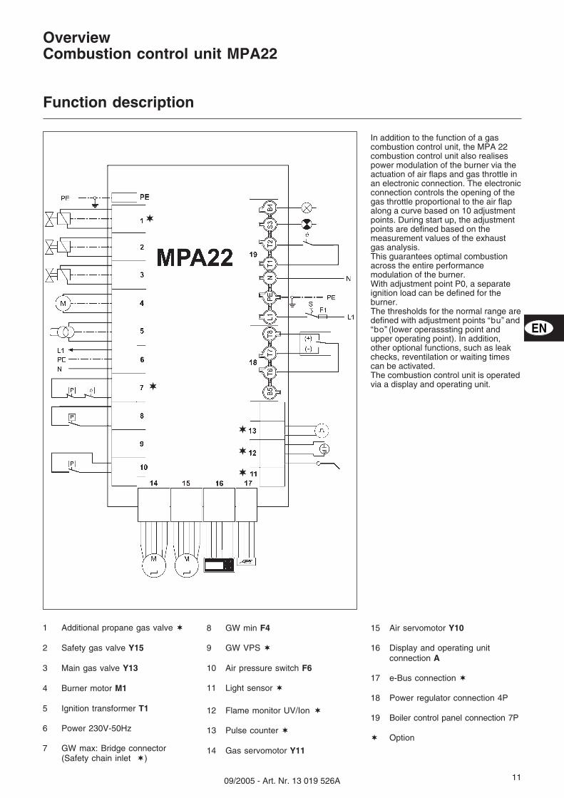
In addition to the function of a gascombustion control unit, the MPA 22combustion control unit also realisespower modulation of the burner via theactuation of air flaps and gas throttle inan electronic connection. The electronicconnection controls the opening of thegas throttle proportional to the air flapalong a curve based on 10 adjustmentpoints. During start up, the adjustmentpoints are defined based on themeasurement values of the exhaustgas analysis.This guarantees optimal combustionacross the entire performancemodulation of the burner.With adjustment point P0, a separateignition load can be defined for theburner.The thresholds for the normal range aredefined with adjustment points “bu” and“bo” (lower operasssting point andupper operating point). In addition,other optional functions, such as leakchecks, reventilation or waiting timescan be activated.The combustion control unit is operatedvia a display and operating unit.
1 Additional propane gas valve �
2 Safety gas valve Y15
3 Main gas valve Y13
4 Burner motor M1
5 Ignition transformer T1
6 Power 230V-50Hz
7 GW max: Bridge connector(Safety chain inlet �)
8 GW min F4
9 GW VPS �
10 Air pressure switch F6
11 Light sensor �
12 Flame monitor UV/Ion �
13 Pulse counter �
14 Gas servomotor Y11
15 Air servomotor Y10
16 Display and operating unitconnection A
17 e-Bus connection �
18 Power regulator connection 4P
19 Boiler control panel connection 7P
� Option
�
�
�
�
�
EN
12 09/2005 - Art. Nr. 13 019 526A
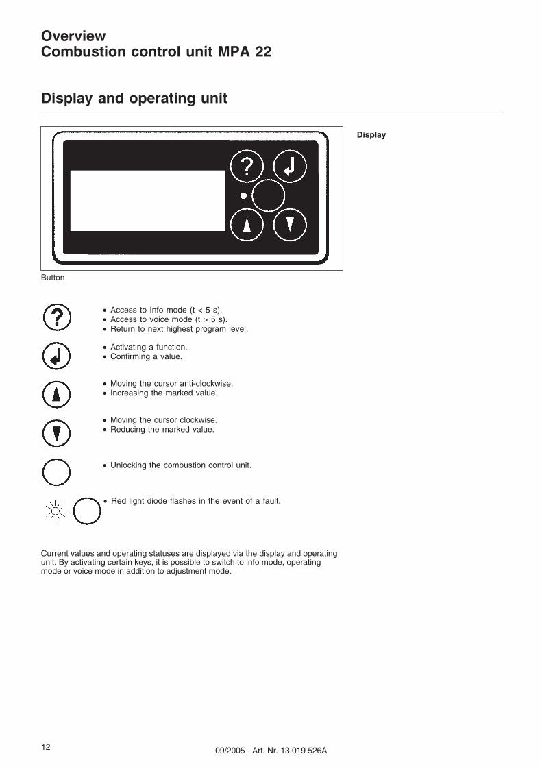
� Access to Info mode (t < 5 s).� Access to voice mode (t > 5 s).� Return to next highest program level.
� Activating a function.� Confirming a value.
� Moving the cursor anti-clockwise.� Increasing the marked value.
� Moving the cursor clockwise.� Reducing the marked value.
� Unlocking the combustion control unit.
� Red light diode flashes in the event of a fault.
OverviewCombustion control unit MPA 22
Display and operating unit
Display
Button
Current values and operating statuses are displayed via the display and operatingunit. By activating certain keys, it is possible to switch to info mode, operatingmode or voice mode in addition to adjustment mode.
1309/2005 - Art. Nr. 13 019 526A
OverviewCombustion control unit MPA 22
Program structure
Adjustment mode
Enter access code
Set key dataP9/P1/P0
Start burner viaboiler regulator
for hotadjustment
Operation at bu(lower operating
point)Back to
operating display
– eBus address– Reventilation time– Waiting time– Pulses per L/m³– Rest pos. Air flap– Delete error list– Check for leaks– Valve 1 check time– Valve 2 check time– Address regulation
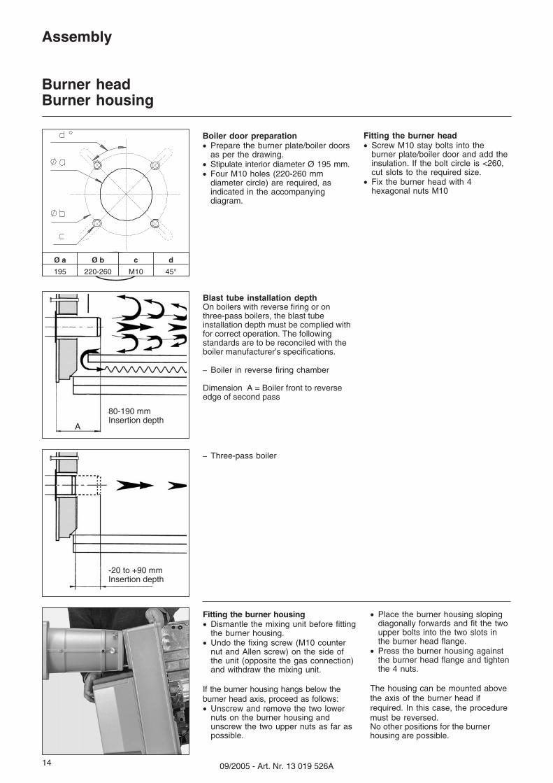
Boiler door preparation� Prepare the burner plate/boiler doors
as per the drawing.� Stipulate interior diameter Ø 195 mm.� Four M10 holes (220-260 mm
diameter circle) are required, asindicated in the accompanyingdiagram.
DE
Assembly
Burner headBurner housing
Fitting the burner housing� Dismantle the mixing unit before fitting
the burner housing.� Undo the fixing screw (M10 counter
nut and Allen screw) on the side ofthe unit (opposite the gas connection)and withdraw the mixing unit.
If the burner housing hangs below theburner head axis, proceed as follows:� Unscrew and remove the two lower
nuts on the burner housing andunscrew the two upper nuts as far aspossible.
� Place the burner housing slopingdiagonally forwards and fit the twoupper bolts into the two slots inthe burner head flange.
� Press the burner housing againstthe burner head flange and tightenthe 4 nuts.
The housing can be mounted abovethe axis of the burner head ifrequired. In this case, the proceduremust be reversed.No other positions for the burnerhousing are possible.
Fitting the burner head� Screw M10 stay bolts into the
burner plate/boiler door and add theinsulation. If the bolt circle is <260,cut slots to the required size.
� Fix the burner head with 4hexagonal nuts M10
Blast tube installation depthOn boilers with reverse firing or onthree-pass boilers, the blast tubeinstallation depth must be complied withfor correct operation. The followingstandards are to be reconciled with theboiler manufacturer’s specifications.
– Boiler in reverse firing chamber
Dimension A = Boiler front to reverseedge of second pass
– Three-pass boiler
80-190 mmInsertion depth
-20 to +90 mmInsertion depth
Ø a Ø b c d
195 220-260 M10 45°
1509/2005 - Art. Nr. 13 019 526A
Assembly
Gas valve assembly
Assembly Gas valve assembly� Press the gas throttle module 5 against
the burner head and tighten the 4nuts. Then secure the gas connectionpipe 3 to the gas throttle module.Check that O-Ring 6 and flat gasket 4are in the correct position.
� Secure gas valve 2 so that thesolenoids of DMV SE are positionedvertically over the gas valve.
� Fit the supplied gas pressure tube 7between the gas throttle module andDMV SE.
� If available, secure external filter 1.� Note the direction of the flow.� Fit a thermally triggered safety valve
and a gas ball valve (provided bymanufacturer) before the gas valve.
� If the position of the gas train isangled, use the enclosedright-angled pressure release pipewith screw connection.If the gas valve is changed, theapplicable guidelines andregulations must be observed. Allconnections should be leak-testedusing foam-producing or similarmaterials.
Caption1 External filter2 Gas valve3 Gas connection pipe4 Flat gasket between gas
connection pipe and gas throttlemodule
5 Gas throttle module6 O-Ring between gas throttle
module and burner head flange7 Gas pressure tube
1 2 3 4 65
7
EN
16 09/2005 - Art. Nr. 13 019 526A
Assembly
Checking/SettingMixer unit for natural gas/propane gas
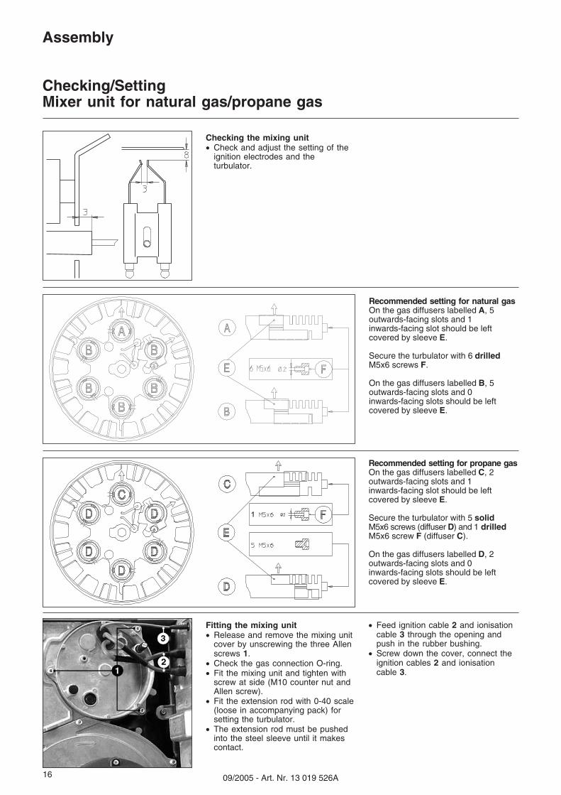
Recommended setting for propane gasOn the gas diffusers labelled C, 2outwards-facing slots and 1inwards-facing slot should be leftcovered by sleeve E.
Secure the turbulator with 5 solidM5x6 screws (diffuser D) and 1 drilledM5x6 screw F (diffuser C).
On the gas diffusers labelled D, 2outwards-facing slots and 0inwards-facing slots should be leftcovered by sleeve E.
1
Checking the mixing unit� Check and adjust the setting of the
ignition electrodes and theturbulator.
Recommended setting for natural gasOn the gas diffusers labelled A, 5outwards-facing slots and 1inwards-facing slot should be leftcovered by sleeve E.
Secure the turbulator with 6 drilledM5x6 screws F.
On the gas diffusers labelled B, 5outwards-facing slots and 0inwards-facing slots should be leftcovered by sleeve E.
Fitting the mixing unit� Release and remove the mixing unit
cover by unscrewing the three Allenscrews 1.
� Check the gas connection O-ring.� Fit the mixing unit and tighten with
screw at side (M10 counter nut andAllen screw).
� Fit the extension rod with 0-40 scale(loose in accompanying pack) forsetting the turbulator.
� The extension rod must be pushedinto the steel sleeve until it makescontact.
� Feed ignition cable 2 and ionisationcable 3 through the opening andpush in the rubber bushing.
� Screw down the cover, connect theignition cables 2 and ionisationcable 3.
1709/2005 - Art. Nr. 13 019 526A
Assembly
Gas supplyElectrical supply
Electrical supply to the burner
For connection of the burner andregulator, the corresponding circuitdiagram is mandatory.The power supply and the electricalconnections must comply with theapplicable standards.
�N.B.:� Before connecting the burner to the
electrical supply, close the gasball valve.
� Set the main switch of the burnercontrol panel to zero.
Before any intervention on theconnector of the gas and air servomo-tors, the display or the e-Bus connec-tion, the burner must be switched off bydisconnecting the 7-pin plug.
Burner motor connectionThe burner is delivered with a neutralwire and earthing for a mains voltage of400V-50Hz AC.The connection cable for the burnermotor must be run through the cablefittings and wired to the terminal strip asindicated in the electrical diagram.Check the direction of rotation of thefan motor (see arrow on burner casing)via manual activation of the burnerprotection device.
Gas valve connection� Connect the gas valve to the plugs
located on the burner (black toblack, grey to grey).
� Insert connector 1 between burnerand gas throttle servomotor inaccordance with the diagram below.
Burner and regulation connectionInsert the 4-pin and 7-pin plug of theboiler control panel in the correspond-ing sockets of the burner.
General regulations for the gas supply� Connection of the gas valve
assembly to the gas mains must becarried out by a recognisedspecialist.
� The cross-section of the gas cablemust be such that the prescribedgas flow pressure at the gas valveinlet is not undershot.
Burner start-up automatically impliesacceptance of the system. This is theresponsibility of the installer or hisrepresentative as he alone canguarantee that the system conforms tothe current standards and regulations.
The installer must hold a licence issuedby the gas authority, must havechecked the system for leaks and musthave vented it.
EN
18 09/2005 - Art. Nr. 13 019 526A
Start-up
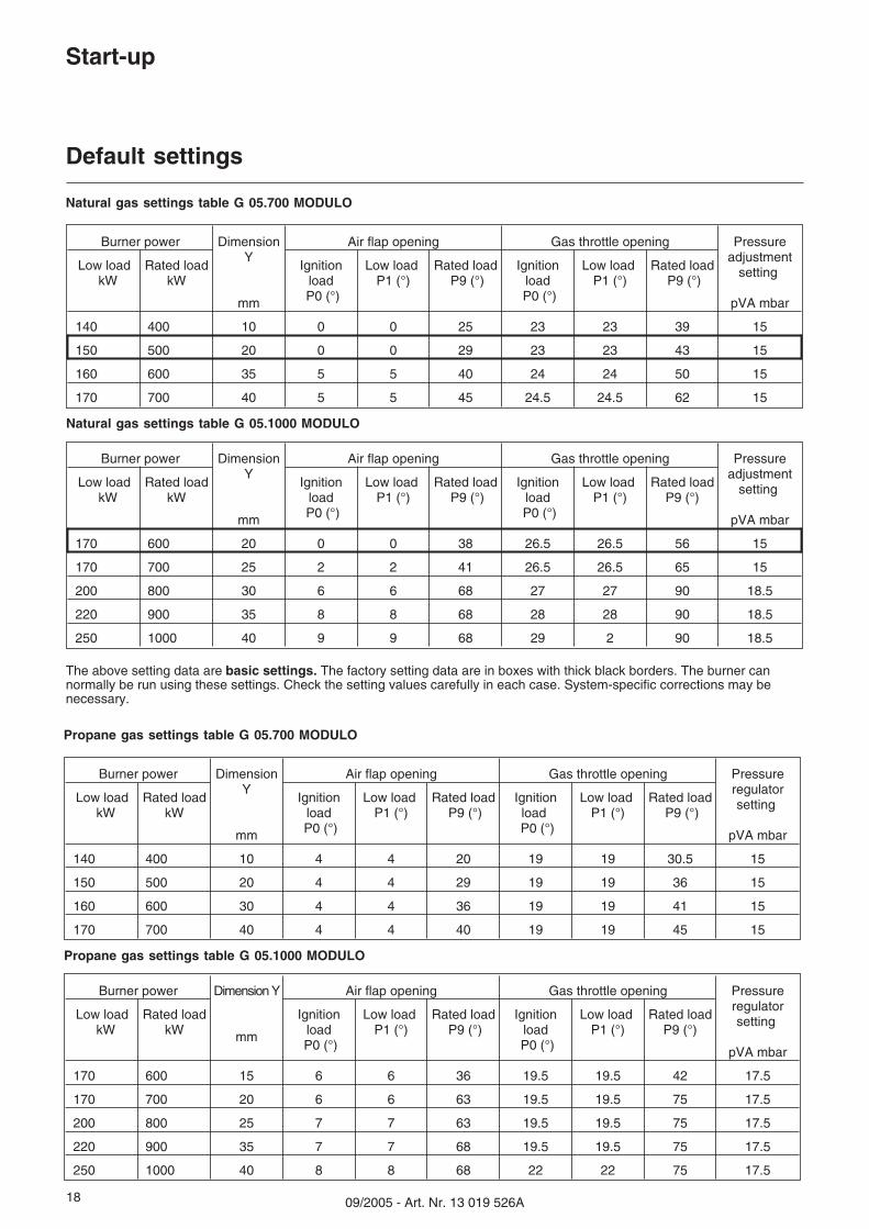
Default settings
Burner power DimensionY
mm
Air flap opening Gas throttle opening Pressureadjustment
setting
pVA mbar
Low loadkW
Rated loadkW
IgnitionloadP0 (°)
Low loadP1 (°)
Rated loadP9 (°)
IgnitionloadP0 (°)
Low loadP1 (°)
Rated loadP9 (°)
140 400 10 0 0 25 23 23 39 15
150 500 20 0 0 29 23 23 43 15
160 600 35 5 5 40 24 24 50 15
170 700 40 5 5 45 24.5 24.5 62 15
Natural gas settings table G 05.700 MODULO
Natural gas settings table G 05.1000 MODULO
Burner power DimensionY
mm
Air flap opening Gas throttle opening Pressureadjustment
setting
pVA mbar
Low loadkW
Rated loadkW
IgnitionloadP0 (°)
Low loadP1 (°)
Rated loadP9 (°)
IgnitionloadP0 (°)
Low loadP1 (°)
Rated loadP9 (°)
170 600 20 0 0 38 26.5 26.5 56 15
170 700 25 2 2 41 26.5 26.5 65 15
200 800 30 6 6 68 27 27 90 18.5
220 900 35 8 8 68 28 28 90 18.5
250 1000 40 9 9 68 29 2 90 18.5
Propane gas settings table G 05.700 MODULO
Propane gas settings table G 05.1000 MODULO
Burner power DimensionY
mm
Air flap opening Gas throttle opening Pressureregulatorsetting
pVA mbar
Low loadkW
Rated loadkW
IgnitionloadP0 (°)
Low loadP1 (°)
Rated loadP9 (°)
IgnitionloadP0 (°)
Low loadP1 (°)
Rated loadP9 (°)
140 400 10 4 4 20 19 19 30.5 15
150 500 20 4 4 29 19 19 36 15
160 600 30 4 4 36 19 19 41 15
170 700 40 4 4 40 19 19 45 15
Burner power Dimension Y
mm
Air flap opening Gas throttle opening Pressureregulatorsetting
pVA mbar
Low loadkW
Rated loadkW
IgnitionloadP0 (°)
Low loadP1 (°)
Rated loadP9 (°)
IgnitionloadP0 (°)
Low loadP1 (°)
Rated loadP9 (°)
170 600 15 6 6 36 19.5 19.5 42 17.5
170 700 20 6 6 63 19.5 19.5 75 17.5
200 800 25 7 7 63 19.5 19.5 75 17.5
220 900 35 7 7 68 19.5 19.5 75 17.5
250 1000 40 8 8 68 22 22 75 17.5
The above setting data are basic settings. The factory setting data are in boxes with thick black borders. The burner cannormally be run using these settings. Check the setting values carefully in each case. System-specific corrections may benecessary.
1909/2005 - Art. Nr. 13 019 526A
Start-up
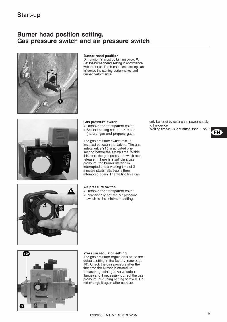
Burner head position setting,Gas pressure switch and air pressure switch
Burner head positionDimension Y is set by turning screw V.Set the burner head setting in accordancewith the table. The burner head setting caninfluence the starting performance andburner performance.
Gas pressure switch� Remove the transparent cover.� Set the setting scale to 5 mbar
(natural gas and propane gas).
The gas pressure switch min. isinstalled between the valves. The gassafety valve Y15 is actuated onesecond before the safety time. Withinthis time, the gas pressure switch mustrelease. If there is insufficient gaspressure, the burner starting isinterrupted and a waiting time of 2minutes starts. Start-up is thenattempted again. The waiting time can
only be reset by cutting the power supplyto the device.Waiting times: 3 x 2 minutes, then 1 hour
Air pressure switch� Remove the transparent cover.� Provisionally set the air pressure
switch to the minimum setting.
Pressure regulator settingThe gas pressure regulator is set to thedefault setting in the factory (see page18). Check the gas pressure after thefirst time the burner is started up(measuring point: gas valve outputflange) and if necessary correct the gaspressure pBr using setting screw S. Donot change it again after start-up.
EN
20 09/2005 - Art. Nr. 13 019 526A
Start-up
Checks before start-upControl unit auto-test
Air Gas
Burner check
Control unit unprogrammed
Control unit auto-testSwitch the burner on via the main switch. The combustion control unit executes anauto-test. If the control unit has not yet been programmed, the display shows“Control unit unprogrammed”
Auto-test of the control unit and of the air and gas servomotors
This display loads the values contained in the combustion control unit.
The control unit has not yet been programmed.
Loading values
100%0%
Pre-start-up check
� Disconnect the burner by unpluggingit from the power supply.
� Close gas valves.� Note the operating regulations of the
heat generator and regulationproducer.
� Check that the gas type and gaspressure are appropriate to theburner.
� Check the gas conduit for leaks� Vent the fuel supply pipes.
� Check the flame pipe insertion depthin accordance with the boilermanufacturer’s instructions.
� Check:– if the fresh air supply and the
exhaust gas paths correspond to theburner power.
– if there is water pressure in heatingcircuit,
– if the circulation pump is running,– if the mixer opens,– if the draught regulator in the
chimney opens,– if the power supply is in order,– thermostat settings,
� Check the direction of rotation of thefan motor (see arrow on burnercasing) via manual activation of theburner protection device.
If all the checks were successful, thenensure that:� Main switch 0/1 is set to zero� Manual/Auto operating type selector
switch is at the centre position� Gas ball valve is closed� Re-energise the burner.
2109/2005 - Art. Nr. 13 019 526A
Start-up
Access to adjustment modeParameters menu: Programming additional functions
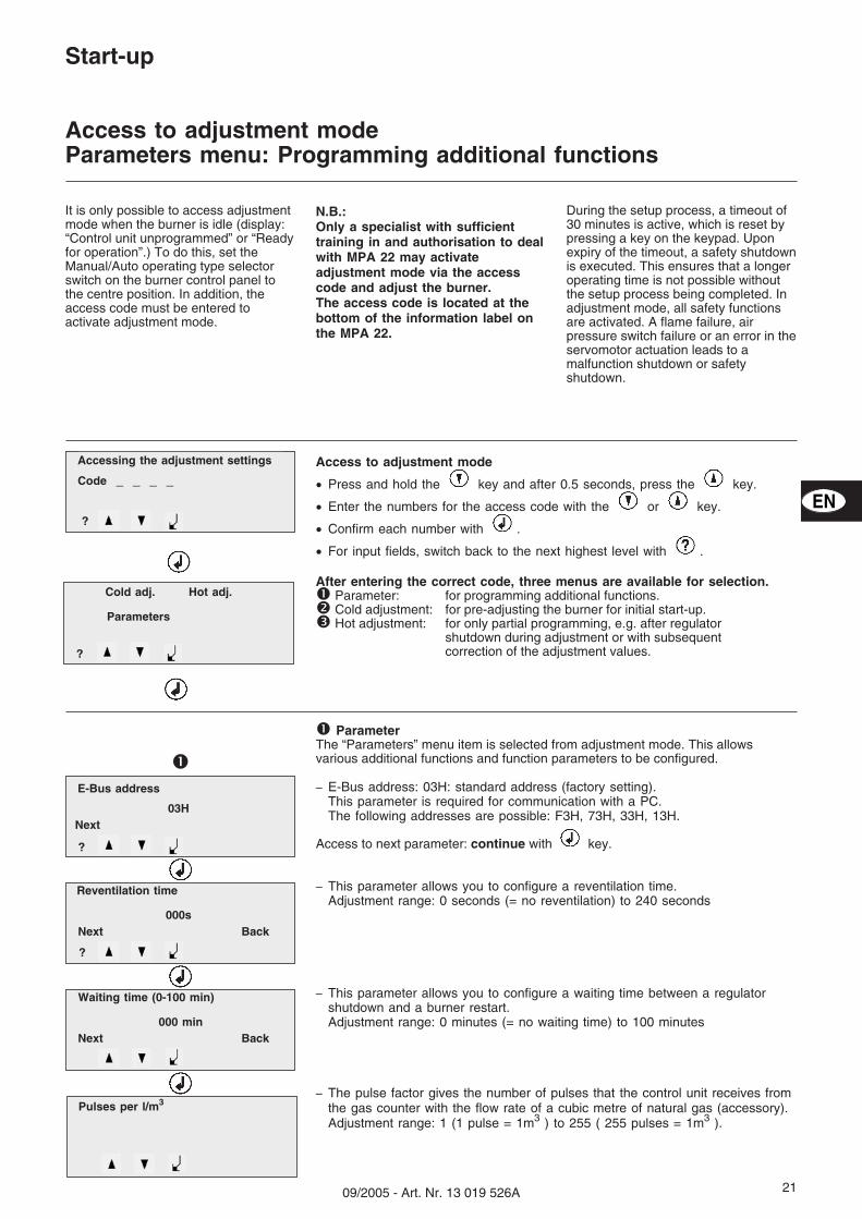
Access to adjustment mode
� Press and hold the key and after 0.5 seconds, press the key.
� Enter the numbers for the access code with the or key.
� Confirm each number with .
� For input fields, switch back to the next highest level with .
After entering the correct code, three menus are available for selection.� Parameter: for programming additional functions.� Cold adjustment: for pre-adjusting the burner for initial start-up.� Hot adjustment: for only partial programming, e.g. after regulator
shutdown during adjustment or with subsequentcorrection of the adjustment values.
� ParameterThe “Parameters” menu item is selected from adjustment mode. This allowsvarious additional functions and function parameters to be configured.
– E-Bus address: 03H: standard address (factory setting).This parameter is required for communication with a PC.The following addresses are possible: F3H, 73H, 33H, 13H.
Access to next parameter: continue with key.
– This parameter allows you to configure a reventilation time.Adjustment range: 0 seconds (= no reventilation) to 240 seconds
– This parameter allows you to configure a waiting time between a regulatorshutdown and a burner restart.Adjustment range: 0 minutes (= no waiting time) to 100 minutes
– The pulse factor gives the number of pulses that the control unit receives fromthe gas counter with the flow rate of a cubic metre of natural gas (accessory).Adjustment range: 1 (1 pulse = 1m3 ) to 255 ( 255 pulses = 1m3 ).
Cold adj. Hot adj.
Parameters
?
Code _ _ _ _
Accessing the adjustment settings
It is only possible to access adjustmentmode when the burner is idle (display:“Control unit unprogrammed” or “Readyfor operation”.) To do this, set theManual/Auto operating type selectorswitch on the burner control panel tothe centre position. In addition, theaccess code must be entered toactivate adjustment mode.
N.B.:Only a specialist with sufficienttraining in and authorisation to dealwith MPA 22 may activateadjustment mode via the accesscode and adjust the burner.The access code is located at thebottom of the information label onthe MPA 22.
During the setup process, a timeout of30 minutes is active, which is reset bypressing a key on the keypad. Uponexpiry of the timeout, a safety shutdownis executed. This ensures that a longeroperating time is not possible withoutthe setup process being completed. Inadjustment mode, all safety functionsare activated. A flame failure, airpressure switch failure or an error in theservomotor actuation leads to amalfunction shutdown or safetyshutdown.
?
Next
E-Bus address
03H
Next Back
Reventilation time
000s
Next Back
Waiting time (0-100 min)
000 min
�
?
Pulses per l/m3
?
EN
22 09/2005 - Art. Nr. 13 019 526A
Next Back
Rest pos. Air flap
00.0°
Next Back
Delete error list
Next Back
Check for leak
Y
Next Back
Valve 1 check time
006s
Next Back
Valve 2 check time
006 s
Next Back
Address Regulation
10H
Connection setup
Save parameters
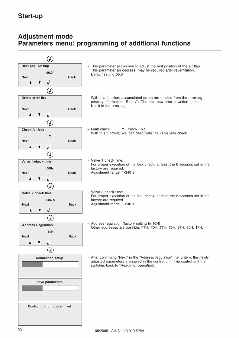
– This parameter allows you to adjust the rest position of the air flap.This parameter (in degrees) may be required after reventilation.Default setting 00.0°
– With this function, accumulated errors are deleted from the error log(display information: “Empty”). The next new error is written underNo. 0 in the error log.
– Leak check: Y= Yes/N= NoWith this function, you can deactivate the valve leak check.
– Valve 1 check time:For proper execution of the leak check, at least the 6 seconds set in thefactory are required.Adjustment range: 1-240 s
– Valve 2 check time:For proper execution of the leak check, at least the 6 seconds set in thefactory are required.Adjustment range: 1-240 s
– Address regulation (factory setting to 10H)Other addresses are possible: F7H, F0H, 77H, 70H, 37H, 30H, 17H.
– After confirming “Next” in the “Address regulation” menu item, the newlyadjusted parameters are saved in the control unit. The control unit thenswitches back to “Ready for operation”.
Start-up
Adjustment modeParameters menu: programming of additional functions
� Cold adjustment (with ball valve closed)In the “Cold adjustment” menu item, the P9/P1/P0 key data are pre-adjusted inaccordance with the setting table (page 18) for the desired burner power.The control unit then calculates the intermediate points P2 to P8 and switches tothe “Hot adjustment” menu.
� Accessing the adjustment mode.
� Select cold adjustment with or .
� Confirm with .
Adjust air and gas setting.
� Position the cursor on air or gas with or .
� Activate with (cursor flashes).
� Set new value with or .
� Confirm with .
Switch between adjustment points P9/P1/P0.
� Position cursor on “Next” or “Back” with or .
� Confirm with .
� If the position “Next” is confirmed for adjustment point P0 with , thecontrol unit calculates the intermediate points P2 to P8 and then switches tothe hot adjustment menu .
Direct access to this menu via adjustment mode/hot adjustment�.
?
Next
Next Back
Low load P1
Air: .. ` . Gas: ..´ .
Next Back
Ignition load P0
?
?
start adjustment
Burner via boiler
regulator for hot adj
?
Air: .. ` . Gas: ..́ .
Air: .. ` . Gas: ..´ .
Full load P9
EN
�
24 09/2005 - Art. Nr. 13 019 526A
Start-up
Adjustment modeHot adjustment menu: Adjusting the burner
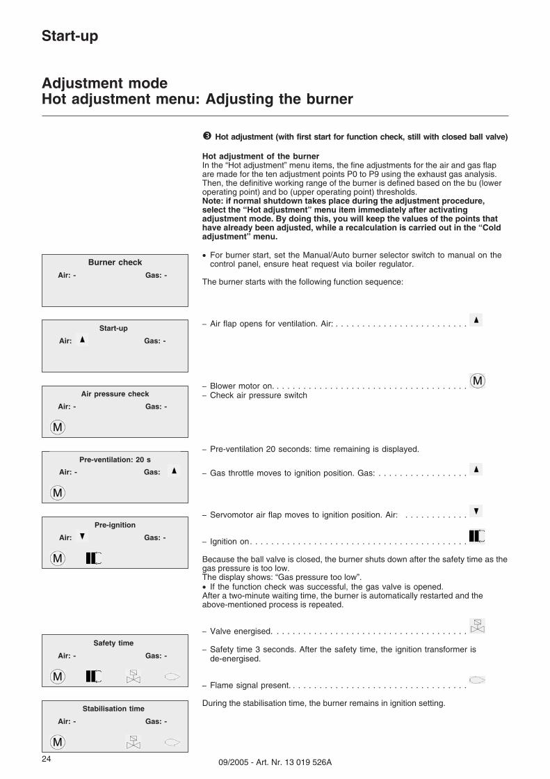
� Hot adjustment (with first start for function check, still with closed ball valve)
Hot adjustment of the burnerIn the “Hot adjustment” menu items, the fine adjustments for the air and gas flapare made for the ten adjustment points P0 to P9 using the exhaust gas analysis.Then, the definitive working range of the burner is defined based on the bu (loweroperating point) and bo (upper operating point) thresholds.Note: if normal shutdown takes place during the adjustment procedure,select the “Hot adjustment” menu item immediately after activatingadjustment mode. By doing this, you will keep the values of the points thathave already been adjusted, while a recalculation is carried out in the “Coldadjustment” menu.
� For burner start, set the Manual/Auto burner selector switch to manual on thecontrol panel, ensure heat request via boiler regulator.
The burner starts with the following function sequence:
Because the ball valve is closed, the burner shuts down after the safety time as thegas pressure is too low.The display shows: “Gas pressure too low”.� If the function check was successful, the gas valve is opened.After a two-minute waiting time, the burner is automatically restarted and theabove-mentioned process is repeated.
During the stabilisation time, the burner remains in ignition setting.
Burner check
Air: - Gas: -
Start-up
Air pressure check
Pre-ventilation: 20 s
Air: - Gas:
Pre-ignition
Air: Gas: -
Safety time
Stabilisation time
Air: Gas: -
Air: - Gas: -
Air: - Gas: -
Air: - Gas: -
2509/2005 - Art. Nr. 13 019 526A
Start-up
Adjustment modeHot adjustment menu: adjusting the burner
Next
Ignition load P0
Air: .. ` . Gas: ..´ .
Next Back
Low load P1
Next Back
Adjustment point P2
Point P3 .... Point P8
Next Back
Full load P9
Next
Lower load point bu (loweroperating point)
Next
Upper load point bo (upperoperating point)
Operation
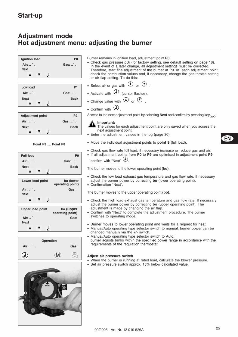
Burner remains in ignition load, adjustment point P0.� Check gas pressure pBr (for factory setting, see default setting on page 18).
In the event of a later change, all adjustment settings must be corrected.Therefore, start fine adjustment of the burner at P9. In each adjustment point,check the combustion values and, if necessary, change the gas throttle settingor air flap setting. To do this:
� Select air or gas with or .
� Activate with (cursor flashes).
� Change value with or .
� Confirm with .
Access to the next adjustment point by selecting Next and confirm by pressing key .
Important:The values for each adjustment point are only saved when you access thenext adjustment point.
� Enter the adjustment values in the log (page 30).
� Move the individual adjustment points to point 9 (full load).
� Check gas flow rate full load, if necessary increase or reduce gas and air.� If all adjustment points from P0 to P9 are optimised in adjustment point P9,
confirm with “Next” .
The burner moves to the lower operating point (bu).
� Check the low load exhaust gas temperature and gas flow rate, if necessaryadjust the burner power by correcting bu (lower operating point).
� Confirmation “Next”.
The burner moves to the upper operating point (bo).
� Check the high load exhaust gas temperature and gas flow rate. If necessaryadjust the burner power by correcting bo (upper operating point). Theadjustment is made by changing the air flap.
� Confirm with “Next” to complete the adjustment procedure. The burnerswitches to operating mode.
� Burner moves to lower operating point and waits for a request for heat.� Manual/Auto operating type selector switch to manual: burner power can be
changed manually via the +/- switch.� Manual/Auto operating type selector switch to Auto:
burner adjusts bu/bo within the specified power range in accordance with therequirements of the regulation thermostat.
Adjust air pressure switch� When the burner is running at rated load, calculate the blower pressure.� Set air pressure switch approx. 15% below calculated value.
Air: .. ` . Gas: ..´ .
Air: .. ` . Gas: ..´ .
Air: .. ` . Gas: ..´ .
Air: .. ` . Gas:
Air: .. ` . Gas:
Air: .. ` . Gas:
EN
EN
26 09/2005 - Art. Nr. 13 019 526A
Start-up
Operating mode
Burner check
Air: Gas:
Start-up
Air: Gas:
Air pressure check
Pre-ventilation: 20 s
Pre-ignition
Safety time
Stabilisation time
Operation
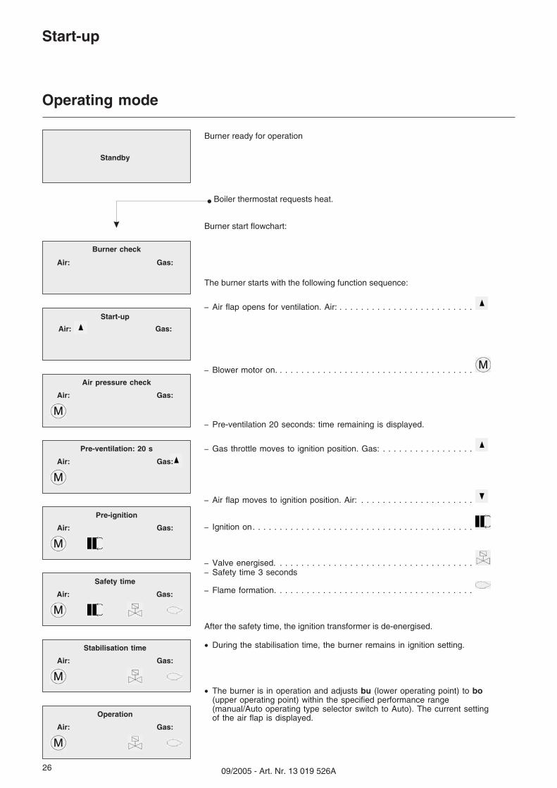
Burner ready for operation
Boiler thermostat requests heat.
Burner start flowchart:
The burner starts with the following function sequence:
After the safety time, the ignition transformer is de-energised.
� During the stabilisation time, the burner remains in ignition setting.
� The burner is in operation and adjusts bu (lower operating point) to bo(upper operating point) within the specified performance range(manual/Auto operating type selector switch to Auto). The current settingof the air flap is displayed.
Standby
Air: Gas:
Air: Gas:
Air: Gas:
Air: Gas:
Air: Gas:
Air: Gas:
2709/2005 - Art. Nr. 13 019 526A
Start-up
Info modeVoice mode
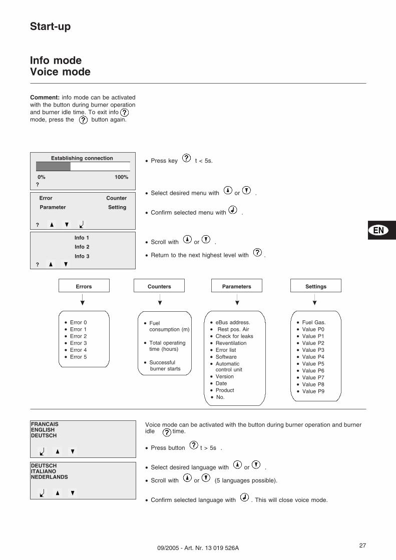
� Press key t < 5s.
� Select desired menu with or .
� Confirm selected menu with .
� Scroll with or .
� Return to the next highest level with .
Error Counter
Parameter Setting
?
Establishing connection
?0% 100%
Info 1
Info 2
?
Info 3
Parameters SettingsCountersErrors
Comment: info mode can be activatedwith the button during burner operationand burner idle time. To exit infomode, press the button again.
Burner and boiler servicing can onlycarried out by a trained specialist.The system operator is advised totake out a service contract toguarantee regular servicing.
N.B.:Before maintenance and cleaning work,completely separate the burner fromthe mains, including the power supplyAC motor, and close the gas ball valve.
A1 Combustion control unitA4 Display and operating unitB10 Ionisation bridgeF6 Air pressure switchF12 Protective motor relayK1 Motor contactorM1 Burner motorT1 Ignition transformer (concealed)Y10 Servomotor air flap7 Control panel8 Blast tube13 Burner cover113 Air box
Maintenance
Checking the exhaust gas temperature� Check the exhaust gas temperature.� Clean the boiler if the exhaust gas
temperature is over 30 K above thestart-up value.
Checking the ignition electrodesand the mixing unit.� Disconnect the 2 ignition cables
from the ignition transformer.� Remove the grommet for the two
cables from the cover by pressinginto the burner head.
� Unscrew completely the 3 screwssecuring the cover.
� Slip the cover off over the cables.� Loosen the side screw securing the
mixing unit.� Pull out the mixing-ignition unit.� Check the condition of the turbulator.� Check the position of the ignition
electrodes and the turbulator.� If necessary, remove dust from the
parts accessible with the coverremoved.
� Check the presence and condition ofthe O-ring seal J1 when assembling.
Cleaning the fan� Disconnect the motor by unplugging
it from the power supply.� Unscrew the 7 screws of the motor panel.� Remove the panel and motor, taking
care not to damage the gaspressure tube of the differential airpressure switch.
� “Dry” clean the air pressure pipes.� Do not use pressurised materials.� Take out the 4 screws securing the
air guiding piece.� Thoroughly clean the air duct and fan.� Reassemble.
2909/2005 - Art. Nr. 13 019 526A
ValvesNo special maintenance is required forthe valves.Valves must not be repaired.Defective valves must be replaced by aqualified professional, who must checkthe leak, function and combustionvalues following replacement.
Remove the blast tube.To carry out this procedure, thecombustion chamber door must beopened or the burner removed.– Variant 1 -Access via the
combustion chamber doors� Remove the mixer control/ignition
device.� Loosen the 3 fixing screws on the
blast tube support by 1 to 2 turns.N.B.: the screws are threaded to theleft (Allen 3).
� Remove the blast tube, check,clean, and where necessary, replaceif a deformity is found.
� Refit the blast tube in the reversesequence.
� The space between the blast tubeand the door insulation should befitted with flameproof material.
– Variant 2 - Removing the burner� Remove the mixer control/ignition
device.� Loosen the electrical connections.� Remove the gas valve assembly.� Unscrew the gas connection
(2 M8 nuts).� Loosen the burner housing
(2 M8 screws) and remove.Do notdamage electrical cables.
� Unscrew the burner head and thenproceed as under variant 1.
� Refit in the reverse sequence.
PrecautionsAfter each intervention, check thecombustion performance under realoperating conditions (doors shut,cover fitted etc.).Note down the results in thecorresponding report forms.
Replacing the filter on the gas valveThe filter must be checked once a yearand replaced if dirty.Pocket filter:� Release the cover fixing screws on
the filter.� Remove the filter.� Insert new filter.� Refit the cover with the screws.Tube filter:� Dismantle the gas connection flange
at the inlet side.� Remove the filter.� Insert new filter.� Fit a gas connection flange.� Open the manual stop valve; check
tightness.
Cleaning the hood� Clean the cover with water and a
Fault diagnosis and repairBefore carrying out fault diagnosis,check that the basic requirements forcorrect operation are being fulfilled:
� Is there any current?� Is there any gas pressure?� Is the gas stop valve open ?� Are all control and safety devices,
such as the boiler thermostat,low-water detector, limit switch, etc.adjusted properly?
Error/fault Cause Corrective action
Display without information No mains voltage presentExternal cut-out defectiveDisplay-control unit plug-and-socketconnection interruptedDisplay defectiveMPA 22 defective
CheckCheck/replaceCheck/establish connection
ReplaceReplace
Display “Safety chain” No feedback on terminal 7 Insert bridge connector or givenCheck switch/limiter
Motor does not start Control unit-motor plug-and-socket
connection interrupted
Capacitor defective
Motor defective
Control unit/servomotors feedback not
correct
Establish connection
Check/replace
Check/replace
Control unit/servomotors
Check/replace
Motor only runs briefly Air pressure switch does not activateGas pressure switch does not activateGas filter dirtyMagnetic valve V1 does not openNo gas available
Check/change adjustmentCheck/change adjustmentClean/replace gas filterCheck/replace compact valveNotify gas supplierNote: in the event of a gas shortage,the waiting time can be reset byde-energising the burner (7-pin plug)
Burner does not start Compact valve defectiveIgnition transformer defectiveIgnition electrode position/Ignition cableMPA 22 control unit defectiveIonisation probe/IRD probe
Crack formation on ionisation probe Too much gas on probeCirculation insufficient
Fit solid screws (propane gas set)
If a fault occurs on the burner, the redlight diode flashes on the display unit.At the same time, the cause of the faultis displayed and a fault code isdisplayed.
EN
32 09/2005 - Art. Nr. 13 019 526A
Adresse Service-Hotline
ELCO Austria GmbHAredstr.16-182544 Leobersdorf
0810-400010
ELCO Belgium n.v./s.a.Pontbeeklaan-531731 Zellik
02-4631902
ELCOTHERM AGSarganserstrasse 1007324 Vilters
0848 808 808
ELCO GmbHDreieichstr.1064546 Mörfelden-Walldorf
0180-3526180
ELCO France18 rue des Buchillons74106 Annemasse
0450877624
ELCO-Rendamax B.V.Amsterdamsestraatweg 271410 AB Naarden
035-6957350
Fabriqué en EU. Made in EU. Hergestellt in der EU. Gefabriceerd in de EUDocument non contractuel. Non contractual document. Angaben ohne Gewähr.Niet-contractueel document


![Lecture 28 industrial robotics [compatibility mode]](https://static.documents.pub/doc/80x56/55a9badc1a28abbf488b4882/lecture-28-industrial-robotics-compatibility-mode.jpg)


![AMC 20-28 Continuity Issue Clean [Compatibility Mode]](https://static.documents.pub/doc/80x56/5868bcad1a28aba27d8b56e9/amc-20-28-continuity-issue-clean-compatibility-mode.jpg)


![Tiet 28 Dan Nhiet [Compatibility Mode]](https://static.documents.pub/doc/80x56/577d204e1a28ab4e1e928077/tiet-28-dan-nhiet-compatibility-mode.jpg)
