235 62(2011)3, 235-248 UDC 629.5.028.722:531:678.6 Ivan ĆATIPOVIĆ Većeslav ČORIĆ Jadranka RADANOVIĆ An Improved Stiffness Model for Polyester Mooring Lines Original scientific paper The stiffness model of highly extensible polyester mooring lines is studied. Mooring lines are considered within coupled dynamic model of a moored floating object. In more detail, deepwater mooring with taut polyester mooring lines is observed. In this case mooring line is modelled as an extensible cable without bending and torsional stiffness. Movements are assumed to be three-di- mensional, so it is necessary to examine large displacement model. In longitudinal strain calculation the material of the mooring line is considered as nonlinear. A large elongation value is examined within the stiffness model. Inertial forces of the mooring line are also considered. Hydrodynamic loads due to surrounding fluid are taken into account with the Morison equation. Due to nonlinear properties of mooring lines calculations have to be done in time domain. On these assumptions, derivation of a mooring line finite element is presented for static and dynamic analysis. A floating object is modelled as a rigid body with six degrees of freedom and with small displacements as- sumption. Hydrodynamic coefficients are calculated in a specified frequency domain; therefore, mapping from the frequency to the time domain is necessary. Comparison between the improved model developed in this paper and current equivalent model is done. A simple mooring line that can be analytically described was the base for comparison. The improved model achieved better agreement with the analytical result. Keywords: coupled model, dynamic response, finite element method, large elongation value, mooring,time domain, polyester rope Poboljšani model krutosti poliesterskih sidrenih linija Izvorni znanstveni rad U članku se proučava model krutosti jako rastezljivih sidrenih poliesterskih linija. Sidrene linije razmatraju se unutar spregnutog modela koji opisuje usidreni plutajući objekt. Iscrpnije, razmatra se sidreni sustav s nategnutim sidrenim linijama od poliestera za sidrenje na velikim dubinama. U ovom slučaju sidrena se linija modelira kao rastezljivo uže bez savojne i torzijske krutosti. Pret- postavlja se da su gibanja trodimenzionalna, stoga treba ispitati model s velikim pomacima. Kod proračuna uzdužne deformacije uzima se u obzir nelinearnost materijala sidrene linije. Visoki iznos istezanja razmatra se u okviru modela krutosti. Inercijske sile koje djeluju na sidrenu liniju također se uzimaju u obzir. Hidrodinamička opterećenja koja nastaju zbog okolnoga fluida proračunavaju se pomoću Morisonove jednadžbe. Zbog nelinearnih značajki sidrenoga sustava svi proračuni se moraju provesti u vremenskoj domeni. Na osnovi navedenih pretpostavki prikazan je izvod konačnog elementa sidrene linije za statički i dinamički slučaj. Plutajući objekt razmatra se kao kruto tijelo sa šest stupnjeva slobode i uz pretpostavku malih pomaka. Hidrodinamički koeficijenti prvo se proračunavaju u frekvencijskoj domeni, a zatim se provodi preslikavanje iz frekvencijske u vremensku domenu. Provedena je usporedba između poboljšanog modela koji je razvijen u ovom radu i jednoga suvremenog modela. Osnova za usporedbu jedna je sidrena linija za koju se mogu dobiti analitički rezultati. Poboljšani model postigao je bolje slaganje rezultata s analitičkim modelom. Ključne riječi: dinamički odziv, rastezljivost, poliestersko uže, sidrenje, spregnuti model, metoda konačnih elemenata, vremenska domena Authors’ Address (Adresa autora): University of Zagreb, Faculty of Mechanical Engineering and Naval Architecture Ivana Lučića 5, 10 000 Zagreb, Croatia E-mail: [email protected]Received (Primljeno): 2011-03-08 Accepted (Prihvaćeno): 2011-04-12 Open for discussion (Otvoreno za raspravu): 2012-10-01 1 Introduction Polyester mooring lines endure high elongation during exploita- tion. Breaking point can be usually found at 15% elongation. Taut polyester lines can form a part of deep-water mooring solution. The characteristics of such mooring system are significantly influenced by extensibility of polyester rope. The stiffness of mooring system is especially sensitive to elongation of mooring lines. A part of this problem is nonlinear stress-strain relation of polyester fibres. A coupled dynamic model is recommended way to solve a deep-water mooring problem. This model is composed of dynam- ics of mooring lines and a floating body dynamics. Inertial and restoring forces of the mooring line as well as hydrodynamic loads are examined. Dynamics of the floating body incorporates environmental loads such as: wave loads of the first and the second order, wind loads and sea current loads. Added mass, damping due to wave radiation and due drag resistance as well as hydrostatic forces are also considered. It should be noted that
Transcript
23562(2011)3, 235-248
AN IMPROVED STIFFNESS MODEL FOR POLYESTER MOORING LINES I. ĆATIPOVIĆ, V. ČORIĆ, J. RADANOVIĆUDC 629.5.028.722:531:678.6
Ivan ĆATIPOVIĆ
Većeslav ČORIĆ
Jadranka RADANOVIĆ
An Improved Stiffness Model for Polyester Mooring Lines
Original scientifi c paper
The stiffness model of highly extensible polyester mooring lines is studied. Mooring lines are considered within coupled dynamic model of a moored fl oating object. In more detail, deepwater mooring with taut polyester mooring lines is observed. In this case mooring line is modelled as an extensible cable without bending and torsional stiffness. Movements are assumed to be three-di-mensional, so it is necessary to examine large displacement model. In longitudinal strain calculation the material of the mooring line is considered as nonlinear. A large elongation value is examined within the stiffness model. Inertial forces of the mooring line are also considered. Hydrodynamic loads due to surrounding fl uid are taken into account with the Morison equation. Due to nonlinear properties of mooring lines calculations have to be done in time domain. On these assumptions, derivation of a mooring line fi nite element is presented for static and dynamic analysis. A fl oating object is modelled as a rigid body with six degrees of freedom and with small displacements as-sumption. Hydrodynamic coeffi cients are calculated in a specifi ed frequency domain; therefore, mapping from the frequency to the time domain is necessary. Comparison between the improved model developed in this paper and current equivalent model is done. A simple mooring line that can be analytically described was the base for comparison. The improved model achieved better agreement with the analytical result.
Keywords: coupled model, dynamic response, fi nite element method, large elongation value, mooring,time domain, polyester rope
Poboljšani model krutosti poliesterskih sidrenih linija
Izvorni znanstveni rad
U članku se proučava model krutosti jako rastezljivih sidrenih poliesterskih linija. Sidrene linije razmatraju se unutar spregnutog modela koji opisuje usidreni plutajući objekt. Iscrpnije, razmatra se sidreni sustav s nategnutim sidrenim linijama od poliestera za sidrenje na velikim dubinama. U ovom slučaju sidrena se linija modelira kao rastezljivo uže bez savojne i torzijske krutosti. Pret-postavlja se da su gibanja trodimenzionalna, stoga treba ispitati model s velikim pomacima. Kod proračuna uzdužne deformacije uzima se u obzir nelinearnost materijala sidrene linije. Visoki iznos istezanja razmatra se u okviru modela krutosti. Inercijske sile koje djeluju na sidrenu liniju također se uzimaju u obzir. Hidrodinamička opterećenja koja nastaju zbog okolnoga fl uida proračunavaju se pomoću Morisonove jednadžbe. Zbog nelinearnih značajki sidrenoga sustava svi proračuni se moraju provesti u vremenskoj domeni. Na osnovi navedenih pretpostavki prikazan je izvod konačnog elementa sidrene linije za statički i dinamički slučaj. Plutajući objekt razmatra se kao kruto tijelo sa šest stupnjeva slobode i uz pretpostavku malih pomaka. Hidrodinamički koefi cijenti prvo se proračunavaju u frekvencijskoj domeni, a zatim se provodi preslikavanje iz frekvencijske u vremensku domenu. Provedena je usporedba između poboljšanog modela koji je razvijen u ovom radu i jednoga suvremenog modela. Osnova za usporedbu jedna je sidrena linija za koju se mogu dobiti analitički rezultati. Poboljšani model postigao je bolje slaganje rezultata s analitičkim modelom.
Polyester mooring lines endure high elongation during exploita-tion. Breaking point can be usually found at 15% elongation. Taut polyester lines can form a part of deep-water mooring solution. The characteristics of such mooring system are signifi cantly infl uenced by extensibility of polyester rope. The stiffness of mooring system is especially sensitive to elongation of mooring lines. A part of this problem is nonlinear stress-strain relation of polyester fi bres.
A coupled dynamic model is recommended way to solve a deep-water mooring problem. This model is composed of dynam-ics of mooring lines and a fl oating body dynamics. Inertial and restoring forces of the mooring line as well as hydrodynamic loads are examined. Dynamics of the fl oating body incorporates environmental loads such as: wave loads of the fi rst and the second order, wind loads and sea current loads. Added mass, damping due to wave radiation and due drag resistance as well as hydrostatic forces are also considered. It should be noted that
236 62(2011)3, 235-248
I. ĆATIPOVIĆ, V. ČORIĆ, J. RADANOVIĆ AN IMPROVED STIFFNESS MODEL FOR POLYESTER MOORING LINES
the coupled model is solved in the time domain because of the nonlinear properties of mooring system.
Elastic rod theory is a cornerstone for the mooring line dy-namics in this study. This theory was derived by Nordgen [1] and Garrett [2]. Nordgen described equation of large motions of elastic rod in terms of centreline position. Garrett incorporated large strain assumptions and suggested fi nite element method (FEM) for numerical calculation. Three papers concerning coupled dynamics of moored vessel attracted special attention of ISSC 2006 Technical Committee 1.2. [3]. Tahar & Kim [4] developed a computer program for hull/mooring/riser coupled dy-namic analysis of a tanker based turret-moored FPSO. Garrett [5] performed a fully coupled global analysis of fl oating production system, including the vessel, the mooring and the riser system. Kim et al. [6] solved simultaneously the vessel and mooring line dynamics. The vessel global motions and mooring tension were tested at the wave basin of Offshore Technology Research Center (Texas, USA) for the non-parallel wind-wave-current 100-year hurricane condition in the Gulf of Mexico. Stiffness nonlinearity of polyester mooring cables was studied by Fern-andes et al.[7]. They examined acceptance tests performed with actual full scale cables. As a result they suggested a formula for specifi c modulus of polyester ropes in terms of dynamic analysis. Tjavaras et al. [8] studied numerically the mechanics of highly extensible cables. In this model a nonlinear stress-strain relation is employed. Numerical solution was based on fi nite difference scheme. Tahar & Kim [9] examined coupled dynamics analysis of fl oating structures with polyester mooring lines. Their math-ematical model allowed relatively large elongation of polyester rope and nonlinear stress-strain relationship. The mooring line dynamics was based on elastic rod theory. Numerical calculations are done utilizing nonlinear FEM.
A novel procedure for the polyester mooring lines is presented in the paper. This procedure has an improved approximation of the mooring line stiffness, taking into account nonlinear ten-sion-elongation relationship. Development of the procedure is done within the coupled dynamic analysis of the moored vessel. Therefore, a new kind of the coupled dynamic model is formed and it can be used for better evaluation of highly extensible polyester mooring lines.
2 Mathematical model
2.1 Dynamics of the mooring line
Elastic rod theory [1],[2] is a cornerstone for the mathematical model. The behaviour of a slender rod is expressed in terms of the centreline position. Movements are three-dimensional, so it is necessary to examine large displacement model. High elongation value of the mooring line is considered for the modelling of the stiffness. Nonlinearity of tension-elongation relationship is taken into account. The cross-section is assumed to be homogeneous and circular. Bending and torsional stiffness are neglected as well as shear deformation and rotary inertia terms. Governing equa-tions are treated in global coordinate system, so there is no need for any kind of coordinate system transformation.
2.1.1 Motion equation
The centreline of a deformed rod is described by a space curve [10]. In governing equations the space curve is defi ned by
a position vector r. Any point on the curve is defi ned by an arc-length of the extended rod s . In this case, a unit tangent vector of the space curve is given as
(1)
with
(2)
Within dynamic analysis the position vector r is also func-tion of the time t. A segment of the mooring line is shown in n Figure 1 where:
s – arc-length of the extended mooring lineF – cross-section internal forceq – distributed loadp – hydrostatic pressure of the sea waterm – distributed mass of the extended mooring liner – acceleration of the segment.
Figure 1 Segment of the mooring lineSlika 1 Diferencijalni element sidrene linije
Archimedes’ principle states that the buoyancy force exerted on an object completely enclosed by a fl uid is equal to the weight
ur= d
d s
u = 1.
23762(2011)3, 235-248
AN IMPROVED STIFFNESS MODEL FOR POLYESTER MOORING LINES I. ĆATIPOVIĆ, V. ČORIĆ, J. RADANOVIĆ
of the fl uid displaced by the object. The segment of the mooring line is not completely enclosed by the sea water, since its ends are attached to rests of the mooring line, see Figure 1. In order to apply Archimedes’ force it is necessary to follow a derivation of Sparks [11], illustrated in Figure 2.
Figure 2 Transformation of the hydrostatic pressure distribu-tion
Slika 2 Transformacija rasporeda hidrostatskog tlaka
The real distribution of the hydrostatic pressure acting on the segment (a) is replaced by a sum of the hydrostatic pressure of the completely immersed segment or distributed buoyancy (b) and outward-pointing forces at the segment’s ends (c). Absolute value of the fi rst outward-pointing force is given as
(3)
where A is cross-section area of the mooring line. In the next step it is necessary to defi ne equivalent loads and forces acting on the segment. Distributed buoyancy q
B is added to distributed load of
the segment, see Figure 2 part (b)
(4)
where qE is effective distributed load. Force P must be added to
the internal force F
(5)
where FE represents cross-section effective force. According to
(4) and (5) it is possible to defi ne an equivalent segment of the mooring line, presented in Figure 3.
Force equilibrium on the equivalent segment of the mooring line leads to the motion equation
(6)
where superposed dot denotes differentiation with respect to time. Moment equilibrium on the equivalent segment can be expressed as
(7)
where × denotes vector product. The vector product from the right hand side of (6) with dr/d s yields, after some manipulations of triple vector product [10]
(8)
where · denotes scalar product. According to (1) and (2) dr/d s is the unit tangent vector u of the space curve, so the following equation can be formed
(9)
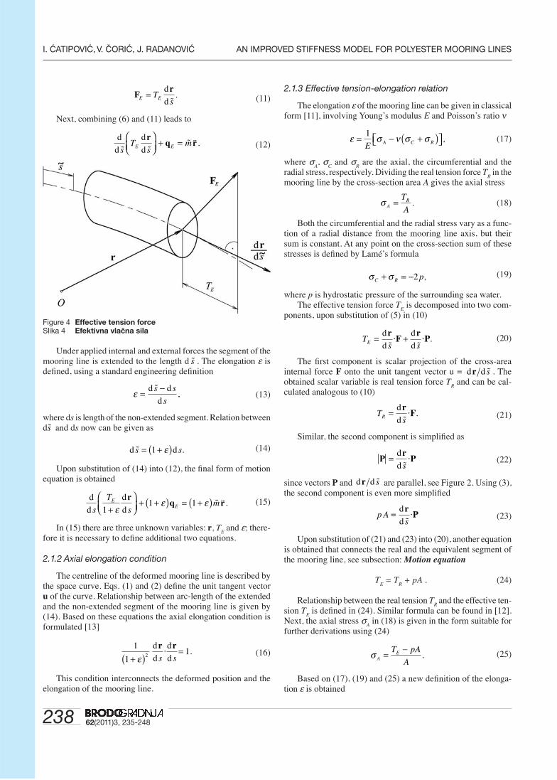
The term contained in the second parentheses of (8) represents scalar projection of F
E in the direction of the unit tangent vector
u. Overview of Figure 4 leads to
(10)
Scalar variable TE in the previous equation denotes effec-
tive tension force [11], [12]. Eq. (8) is simplifi ed using (9) and (10)
P = pA,
q q qE B= + ,
F F PE = + ,
Figure 3 Equivalent segment of the mooring lineSlika 3 Ekvivalentni diferencijalni element sidrene linije
d
d
Fq rE
Esm+ = ,
d
d
rF 0
s E× = ,
d
d
d
d
d
d
d
d
r rF
rF
r0
s s s sE E· · ,⎛⎝⎜
⎞⎠⎟
−⎛⎝⎜
⎞⎠⎟
=
d
d
d
d
r rs s
· .= 1
TsE E= d
d
rF· .
238 62(2011)3, 235-248
I. ĆATIPOVIĆ, V. ČORIĆ, J. RADANOVIĆ AN IMPROVED STIFFNESS MODEL FOR POLYESTER MOORING LINES
(11)
Next, combining (6) and (11) leads to
(12)
Figure 4 Effective tension forceSlika 4 Efektivna vlačna sila
Under applied internal and external forces the segment of the mooring line is extended to the length d s . The elongation ε is defi ned, using a standard engineering defi nition
(13)
where ds is length of the non-extended segment. Relation between ds and ds now can be given as
(14)
Upon substitution of (14) into (12), the fi nal form of motion equation is obtained
(15)
In (15) there are three unknown variables: r, TE and ε; there-
fore it is necessary to defi ne additional two equations.
2.1.2 Axial elongation condition
The centreline of the deformed mooring line is described by the space curve. Eqs. (1) and (2) defi ne the unit tangent vector u of the curve. Relationship between arc-length of the extended and the non-extended segment of the mooring line is given by (14). Based on these equations the axial elongation condition is formulated [13]
(16)
This condition interconnects the deformed position and the elongation of the mooring line.
2.1.3 Effective tension-elongation relation
The elongation ε of the mooring line can be given in classical form [11], involving Young’s modulus E and Poisson’s ratio ν
(17)
where σA, σ
C and σ
R are the axial, the circumferential and the
radial stress, respectively. Dividing the real tension force TR in the
mooring line by the cross-section area A gives the axial stress
(18)
Both the circumferential and the radial stress vary as a func-tion of a radial distance from the mooring line axis, but their sum is constant. At any point on the cross-section sum of these stresses is defi ned by Lamé’s formula
(19)
where p is hydrostatic pressure of the surrounding sea water.The effective tension force T
E is decomposed into two com-
ponents, upon substitution of (5) in (10)
(20)
The fi rst component is scalar projection of the cross-area internal force F onto the unit tangent vector u = d dr s . The obtained scalar variable is real tension force T
R and can be cal-
culated analogous to (10)
(21)
Similar, the second component is simplifi ed as
(22)
since vectors P and d dr s are parallel, see Figure 2. Using (3), the second component is even more simplifi ed
(23)
Upon substitution of (21) and (23) into (20), another equation is obtained that connects the real and the equivalent segment of the mooring line, see subsection: Motion equation
T
E = T
R + pA . (24)
Relationship between the real tension TR and the effective ten-
sion TE is defi ned in (24). Similar formula can be found in [12].
Next, the axial stress σA in (18) is given in the form suitable for
further derivations using (24)
(25)
Based on (17), (19) and (25) a new defi nition of the elonga-tion ε is obtained
Fr
E ETs
= d
d.
d
d
d
dsT
smE E
rq r
⎛⎝⎜
⎞⎠⎟
+ = .
ε = −d d
d
s s
s,
d ds s= +( )1 ε .
d
d
d
ds
T
smE
E11 1
+⎛⎝⎜
⎞⎠⎟
+ +( ) = +( )ε
ε εrq r .
1
112+( )
=ε
d
d
d
d
r rs s
· .
ε σ ν σ σ= − +( )⎡⎣ ⎤⎦1
E A C R ,
σ ART
A= .
σ σC R p+ = −2 ,
Ts sE = +d
d
d
d
rF
rP· · .
TsR = d
d
rF· .
Pr
P= d
d s·
p As
= d
d
rP·
σ AET pA
A= −
.
23962(2011)3, 235-248
AN IMPROVED STIFFNESS MODEL FOR POLYESTER MOORING LINES I. ĆATIPOVIĆ, V. ČORIĆ, J. RADANOVIĆ
(26)
For synthetic ropes Poisson’s ratio is assumed to be [8]
(27)
The fi nal form of effective tension-elongation relationship is defi ned by (26) and (28)
(28)
2.1.4 Axial stiffness of polyester rope
The elongation of a polyester rope does not have linear re-lationship with its tension. A direct simulation of the polyester rope dynamics is extremely complicated. To simplify numerical simulation an empirical formulation is used to model axial stiff-ness AE of the polyester rope [9]
(29)
where BS is minimum breaking strength, T
R is time dependant
real tension, and RHOL is dry weight per unit length of the rope. Constants α and β depend on the type of polyester rope and they are obtained experimentally. The stiffness described by (29) is formulated in terms of the dynamics analysis but it is often used for static calculations. A similar defi nition of polyester Young’s modulus can be found in [7].
2.1.5 Finite element for the static analysis
The effective distributed load qE for the static analysis of the
mooring line is formulated according to (4)
(30)
where qG is distributed weight of dry mooring line. Distributed
buoyancy qB is given as
(31)
where ρ is density of the sea water, and g is gravitational accel-eration. Similarly, q
G is expressed as
(32)
In the above equations, variables A and m are related to the extended case of the mooring line, so they depend on the elon-gation ε. Already in this paper, the Poisson’s ratio of polyester rope is assumed to be 0.5, see (27). Therefore, the volume of any deformed segment is conserved [8]. The cross-section area A and the distributed mass m are formulated as
(33)
(34)
where A and m are related to the non-extended case, so they are constant. Finally, by omitting inertial term in the motion equation (15) and combining with from (30) to (34), the static equation is defi ned as
(35)
The elongation ε formulated by (28) is included in the static equation (35) and the axial elongation condition (16) in incon-venient way for further derivations. Simplifi cation is obtained by using Taylor series [10] for (35)
(36)
and for (16)
(37)
The fi nal form of governing equations for the static analysis is composed of (16), (28) and (35) with simplifi cations accord-ing to (36), (37)
(38)
and
(39)
It should be noted that (39) is intentionally defi ned in ap-proximate form. By observing (16) and (28) an exact form of the axial elongation condition can be obtained, simply by multiplying (16) with (1 + ε)2. As it will be written below, this approximate form of eq. (39) provides a symmetric equation set for numeri-cal calculations.
In (38) and (39) there are two unknown variables: effec-tive tension T
E and the position vector of mooring line r. This
equation set is solved utilizing fi nite element method (FEM). The application of FEM starts from describing (38) and (39) in index notation
(40)
and
(41)
with
i, j = 1, 2, 3 (42)
where prime denotes differentiation with respect to s. Here un-known variables T
E and r
i are approximated as [14]
ri (s) = A
l (s) U
il (43)
ε ν= − −( )⎡⎣⎢
⎤⎦⎥
11 2
E
T
ApE .
ν ≈ 0 5. .
ε = T
AEE .
AE RHOLT
BR
S
= +⎛⎝⎜
⎞⎠⎟
[ ]α β · ,106 N
q q qE B G= + ,
q gB A= −ρ ,
q gG m= .
AA=+1 ε
mm=+1 ε
,
1
11 2 3
+= − + +
εε ε εO( )
1
11 2 32
2 3
+( )= − + +
εε ε εO( ).
d
d
d
dsT T
T
AET
T
AE sE EE
EE− + ⎛
⎝⎜⎞⎠⎟
⎛
⎝⎜⎞
⎠⎟⎡
⎣⎢⎢
⎤
⎦⎥
2 r
⎥⎥+ − =m Ag g 0ρ
1 2 3 12
− + ⎛⎝⎜
⎞⎠⎟
⎡
⎣⎢⎢
⎤
⎦⎥⎥
=T
AE
T
AE s sE E d
d
d
d
r r· .
T TT
AET
T
AEr mE E
EE
Ei− + ⎛
⎝⎜⎞⎠⎟
⎛
⎝⎜⎞
⎠⎟′
⎡
⎣⎢⎢
⎤
⎦⎥⎥
+2 '
gg gi iA− =ρ 0
1 2 3 12
− + ⎛⎝⎜
⎞⎠⎟
⎡
⎣⎢⎢
⎤
⎦⎥⎥
′ ′ =T
AE
T
AEr rE E
j j ,
d
d
d
ds
T
sm AE
1 +⎛⎝⎜
⎞⎠⎟
+ − =ε
ρrg g 0.
240 62(2011)3, 235-248
I. ĆATIPOVIĆ, V. ČORIĆ, J. RADANOVIĆ AN IMPROVED STIFFNESS MODEL FOR POLYESTER MOORING LINES
TE (s) = P
m (s) λ
m (44)
with
m = 1, 2, 3; l = 1, ..., 4 (45)
where Al and P
m are shape functions defi ned in the interval 0 ≤ s ≤
L, where L is length of fi nite element, see Appendix A. Unknown coeffi cients U
il and λ
m can be expresed as
(46)
and
(47)
Galerkin method [15] combining with (43) and (44) is used for the fi nite element discretization of the static equation (40) as follows
(48)
with
(49)
(50)
(51)
(52)
and
n, p = 1, 2, 3; k = 1, ..., 4. (53)
where δij is Kronecker delta. Eq. (48) is the static equation of
fi nite element, where Fil denotes total nodal forces that incor-
porate external nodal forces FilC as well as nodal forces from
distributed dry weight and buoyancy of the mooring line. Knijkl0
is geometric stiffness matrix of the non-extended mooring line. Additional stiffness matrices Knmijkl
1 and Knmpijkl2 can be con-
sidered as change coeffi cients of the geometric stiffness due to the elongation of the mooring line. To clarify, these additional matrices are direct consequence of the simplifi cation used in the mooring line static (35). The simplifi cation is carried out by Taylor series defi ned in (36). Obtained simplifi ed form is shown in (40) using index notation. By close inspection of (40) and (48) the origin of each stiffness matrix can be determined. Thus, the geometric stiffness Knijkl
0 in (48) derives from T rE i′[ ]' in (40). In the same way, additional stiffness matrices Knmijkl
1 and
Knmpijkl2 are derived from T T AE rE E i( ) ′⎡⎣ ⎤⎦
' and T T AE rE E i( ) ′⎡⎣
⎤⎦
2 '
respectively. Further, heaving in mind that the term TE /AE is
the mooring line elongation ε according to (28), Knmijkl1 can be
considered as linear and Knmpijkl2 quadratic change coeffi cient
of the geometric stiffness.Axial elongation condition (41) is also discretized using
Galerkin’s method [15] and combining with (43) and (44) as follows
(54)
with
(55)
(56)
(57)
(58)
Finite element static equation (48) and discretized axial elongation condition (54) are highly nonlinear. Therefore, this equation system is solved using the Newton-Rapson iterative method [10] as follows
(59)
with
(60)
(61)
(62)
(63)
(64)
(65)
In (59) J J Jijkl nil mjk11 12 21, , , Jmn
22 and denote parts of a Jacobian matrix while Ril
1 and Rm2 compose a residual vector. Label (k)
in superscripts denotes number of iteration. Simplifi ed form of eq. (59) for a single fi nite element is given as
(66)
where
(67)
U r U r
U r L U r Li i i i
i i i i
1 2
3 4
0 0= = ′= = ′
( ); ( )
( ); ( )
λλλ
1
2
3
0
2
===
T
T L
T L
E
E
E
( )
( / ).
( )
K K K Unijkl m nmijkl m p nmpijkl n0 1 2+ +( )λ λ λ λ
K P A A snijkl n k l ij
L0
0
= − ′ ′∫ δ d
KAE
P P A A snmijkl n m k l ij
L1
0
1= ′ ′∫ δ d
KAE
P P P A A snmpijkl n m p k l ij
L2
20
1= − ′ ′∫ ( )δ d
F F mg s A g A silC
i
L
i l
L
= + −∫ ∫d d0 0
( )ρ
B B B U U Cmkl n nmkl n p nmpkl jl jk m0 1 2 0+ +( ) − =λ λ λ ,
B P A A smkl m k l
L0
0
= ′ ′∫ d
BAE
P P A A snmkl n
L
m k l1
0
2= − ′ ′∫ d
BAE
P P P A A snmpkl n
L
m p k l2
20
3= ′ ′∫ ( )d
C P sm m
L
= ∫ d0
.
J J
J Jijkl
k k
mjkk
mnk
11 12
21 22
( ) ( )
( ) ( )nil⎡
⎣⎢
⎤
⎦⎥
ΔUU R
Rjk
n
ilk
mkΔλ
⎧⎨⎩
⎫⎬⎭
= −⎧⎨⎩⎪
⎫⎬⎭⎪
1
2
( )
( ),
J K K Kijklk
nijkl m nmijkl m p nmpijkl11 0 1 2( ) = + +λ λ λ(( )( ) ( )k
nkλ
J K K Knilk
nijkl m nmijkl m p nmpijkl12 0 12 3( ) = + +λ λ λ 22( )( ) ( )k
jkkU
J B B B Umjkk
mkl n nmkl n p nmpkl
k21 0 1 2( ) ( )= − + +( )λ λ λ jjl
k( )
J B B U Umnk
nmkl p nmpkl
k
jlk
jk22 1 21
22( ) ( ) ( )= − +( )λ (( )k
R J U Filk
ijklk
jkk
ilk1 11( ) ( ) ( ) ( )= +
R J U Cmk
mjkk
jkk
m2 211
2( ) ( ) ( ) .= +( )
J y Rk k[ ] { } = −{ }( ) ( )
,Δ
y U U U U U U U U U U U U{ } = 11 12 21 22 31 32 1 2 13 14 23 24 33 3λ λ 44 3λ{ }T
U Fjk il+ == 0,
24162(2011)3, 235-248
AN IMPROVED STIFFNESS MODEL FOR POLYESTER MOORING LINES I. ĆATIPOVIĆ, V. ČORIĆ, J. RADANOVIĆ
(68)
Calculations are carried out iteratively according to the fol-lowing algorithm
(69)
(70)
where {Y} is global “nodal displacement” vector, [K] global “stiffness” matrix and {F} is global “nodal force” vector.
By detailed inspection of (59) it can be found that formulation of the Jacobian matrix is symmetrical. As it is known, the Jacobian matrix in most causes is not symmetric when a nonlinear equation system is considered. In this study special effort is invested to achieve this symmetrical form. The symmetry is mainly realized by selecting appropriate form of the axial elongation condition (16). As already written, by Taylor series in (37) and (28) an approximate form of axial elongation condition is given in (39). This form provided a requested basis for the symmetry. Further-more, during formulation of the Newton-Rapson procedure (59), discretized axial elongation condition (54) is multiplied by -1/2 to achieve the complete symmetry. This symmetric form of the Jacobian matrix enables easier numerical implementation utiliz-ing classical FEM codes.
2.1.6 Finite element for the dynamic analysis
Distributed hydrodynamic load qH on the mooring line is
derived utilizing Morison equation [14] as follows
(71)
with
(72)
where ˙ ˙ denotes the length of a vector; A and D are cross-section area and diameter of the non-extended mooring line respectively; C
A, C
M and C
D are added mass, inertial and
drag coeffi cients. In (72), r n is a component of the mooring line acceleration normal to the mooring line, see Figure 5. Analogously, r. n is the normal component of the mooring line velocity. Motion of the surrounding sea water is considered through normal components of water particle acceleration v. n and velocity vn. In the next step, hydrodynamic load needs to be considered within the motion equation (15). Therefore, the effective distributed load q
E for dynamic analysis is formulated
according to (4) and (30)
(73)
The fi nal form of motion equation is derived using (15), (31), (32), (33), (34) and (73) as follows
(74)
It should be noted that in the previous chapter the formulation of the distributed buoyancy q
B is based on the cross-section area
A of the extended mooring line, see (31). In (33), the relation of the cross-section area for extended and non-extended state is formulated based on the elongation ε. For sake of simplicity, the elongation ε is not considered in the derivation of distributed hydrodynamic load in (71), so the cross-section area A as well as the diameter D are assumed to be constant. With same intention, the elongation is neglected in the formulation of acceleration and velocity normal components in (72), where the unit tangent vector dr/d s of the extended mooring line is replaced by dr/ds, see (1) and (14). The elongation is also neglected in the deriva-tion of motion equation (74), so that the term (1 + ε) that should multiply q
H is dropped, see (15) and (73).
Figure 5 Normal component of the mooring line accelerationSlika 5 Normalna komponenta ubrzanja sidrene linije
The axial elongation condition given by (16) must be fulfi lled during dynamic analysis. To obtain symmetric equation set for numeric calculation an approximate form of the condition is chosen as follows
(75)
The fi nal form of governing equations for dynamic analysis is composed of (28), (74) and (75) with simplifi cation according to (36), given in index notation
(76)
R R R R R R R R R R R R{ } = 111
121
211
221
311
321
12
22
131
141
2231
241
331
341
32R R R R
T{ } .
ΔY K Fk k{ } = ⎡⎣ ⎤⎦ { }−1 ( ) ( )
Y Y Yk k{ } = { } + { }+( ) ( )
,1 Δ
q r v v r v rH An
Mn
Dn n n nC A C A C D= − + + − −( )ρ ρ ρ1
2
r r rr r
r r rr
n
n
s s
s
= −⎛⎝⎜
⎞⎠⎟
= −⎛⎝
·
·
d
d
d
d
d
d⎜⎜⎞⎠⎟
= −⎛⎝⎜
⎞⎠⎟
= −
d
d
d
d
d
d
d
d
r
v v vr r
v v vr
s
s sn
n
·
·ss s
⎛⎝⎜
⎞⎠⎟
d
d
r
q q q qE B G H= + + .
d
ds
d
ds
Tm A mE
H1 +⎛⎝⎜
⎞⎠⎟
+ − + =ε
ρrg g q r.
1
11 0
+⎛⎝⎜
⎞⎠⎟
− − =ε
εd
ds
d
ds
r r· .
T TT
AET
T
AEr mE E
EE
Ei− + ⎛
⎝⎜⎞⎠⎟
⎛
⎝⎜⎞
⎠⎟′
⎡
⎣⎢⎢
⎤
⎦⎥⎥
+2 '
gg Ag q mri i iH
i− + =ρ
242 62(2011)3, 235-248
I. ĆATIPOVIĆ, V. ČORIĆ, J. RADANOVIĆ AN IMPROVED STIFFNESS MODEL FOR POLYESTER MOORING LINES
and
(77)
Note that in the above equations there is new label qHi for the
hydrodynamic load to avoid confusion when using index nota-tion. Unknown variables T
E and r
i are approximated in the same
way as for static calculations by (43) and (44), in this case here unknown coeffi cients U
il and λ
m are time dependent.
Finite element discretization of the motion equation (76) is based on Galerkin’s method [15] as follows
(78)
with
(79)
(80)
(81)
and
(82)
where eijk
is Levi-Civita symbol. Eq. (78) is the dynamic equation of fi nite element, where M
ijkl denotes mass matrix due to own
mass; MAijkl
is added mass matrix and FHil is nodal force vector
due to hydrodynamic load. Stiffness matrices Knijkl0 , Knmijkl
1 and Knmpijkl
2 as well as nodal force vector Fil are the same as for the
static case, see (48). The (78) is a second order differential equa-tion. The order of this equation is derated using the fi rst derivate of displacements. As a result, two fi rst order differential equations are obtained, as follows
(83)
(84)
with substitutions
(85)
(86)
(87)
where Vjk is nodal velocity vector. For the sake of simplicity,
time integration is based on trapezoidal integration [10], with sequential formulas
(88)
(89)
where ∆t is time step size and n in superscripts denotes time step number. To achieve time integration of dynamic equation (78) it is necessary to combine (83) with the above formulas
(90)
Discretization of the axial extension condition (77) is also achieved using Galerkin’s method and combining with (43) and (44), as follows:
(91)
with
(92)
(93)
(94)
(95)
Vector Cm is the same as for eq. (54).
Finite element dynamic equations with implemented time inte-gration given by eq. (90) and discretizied axial elongation condition (91) are highly nonlinear. Therefore, the Newton-Rapson iterative method [10] is used to solve this equation set, as follows
(96)
with (97)
(98)
(99)
(100)
(101)
1 1 02
− + ⎛⎝⎜
⎞⎠⎟
⎡
⎣⎢⎢
⎤
⎦⎥⎥
′ ′− − =T
AE
T
AEr r
T
AEE E
j jE .
M mA A sijkl l k ij
L
= −∫ δ d0
M C A A e A e A A U U sijklA
A l ifg v gjh k z fv hz
L
= − ( ) ′ ′∫ ρ d0
F C A A e A e A v U U silH
M l ifg v gjh z j fv hz
L
= ( ) ′ ′ +
+
∫ ρ d0
11
2C A e v A U A U e vD abc b r br s cs adeρ⎛
⎝⎜⎞⎠⎟ −( ) ′⎡⎣ ⎤⎦ dd t dt u eu
L
l ifg v gjh j
A U A U
A e A e v A
−( ) ′⎡⎣ ⎤⎦
′ −
∫ ·
·
0
kk jk z fv hzU A U U s( ) ′⎡⎣ ⎤⎦d
M M U
K K
ijkl ijklA
jk
nijkl m nmijkl m
+( ) +
+ + +0 1λ λ λpp nmpijkl n jk il ilHK U F F2 0( ) + + =λ ,
a b c d e f g h r t u v z, , , , , , , , , ; , , , , ,..., .= =1 2 3 1 4
ˆ ˆ ˆM V K U Fijkl jk nijkl n jk il= − −λ
U Vjk jk=
M M Mijkl ijkl ijklA= +
K K K Knijkl nijkl m nmijkl m p nmpijkl= + +0 1 2λ λ λ
ˆ ,F F Fil il ilH= +
Vt
U U Vjkn
jkn
jkn
jkn( ) ( ) ( ) ( )+ += −( ) −1 12
Δ
Vt
U UtVjk
njkn
jkn
jkn( ) ( ) ( ) ( )+ += −( ) − −1
214 4
Δ ΔVVjk
n( ) ,
ˆ ( ) ( ) ( ) (Mt
U UtVijkl
njkn
jkn
jkn+ + +−( ) −1
21 14 4
Δ Δ)) ( )
( ) ( ) (ˆ
−⎡
⎣⎢
⎤
⎦⎥ =
= − + +
V
K U
jkn
nijkln
nn
jk2 1 1λ nn
ilnF+ +−1 1) ( )ˆ .
( ˆ ˆ ˆ ) ˆB B B U U Cmkl n nmkl n p nmpkl jl jk nm0 1 2+ + +λ λ λ λnn mC− = 0
B P A A smkl m k l
L0
0
= ′ ′∫ d
BAE
P P A A snmkl n m k l
L1
0
1= − ′ ′∫ d
ˆ( )
BAE
P P P A A snmpkl n m p k l
L2
20
1= ′ ′∫ d
ˆ .CAE
P P snm n m
L
= −∫1
0
d
ˆ ˆ
ˆ
( , ) ( , )
( , )
J J
J
ijkln k
niln k
mjkn k
11 1 12 1
21 1
+ +
+ ˆ
ˆ
( , )
(
J
U R
mnn k
jk
n
il
22 1
1
+
⎡
⎣⎢⎢
⎤
⎦⎥⎥
⎧⎨⎩
⎫⎬⎭
= −ΔΔλ
nn k
mn kR
+
+
⎧⎨⎪
⎩⎪
⎫⎬⎪
⎭⎪
1
2 1
, )
( , )ˆ,
ˆ ˆ ˆ( , ) ( , ) (Jt
M Kijkln k
ijkln k
nijkln11 1
214+ += +
Δ++1, )k
nλ
ˆ ˆ( , ) ( , ) ( , )J K Uniln k
nijkln k
jkn k12 1 1 1+ + +=
ˆ ˆ ˆ ˆ( , )J B B Bmjkn k
mkl n nmkl n p nmpk21 1 0 1+ = − + +λ λ λ ll
n k
jln kU2
11( ) + +( , )
( , )
ˆ ˆ ˆ ˆ( , )J C B Bmnn k
mn nmkl p nmpkl22 1 1 21
2
1
22+ = − − + λ(( ) + + +( , )
( , ) ( , )n k
jln k
jkn kU U
11 1
ˆ ˆ ˆ( , ) ( , ) ( ,Rt
M Kiln k
ijkln k
nijkln1 1
21 14+ + += +
Δkk
n jkn k
iln k
ijkln
U F
M
) ( , ) ( , )
(
ˆ
ˆ
λ⎛⎝⎜
⎞⎠⎟
+ +
+
+ +1 1
++ − − −⎛⎝⎜
⎞⎠⎟
12
4 4, ) ( ) ( ) ( )kjkn
jkn
jkn
tU
tV V
Δ Δ
24362(2011)3, 235-248
AN IMPROVED STIFFNESS MODEL FOR POLYESTER MOORING LINES I. ĆATIPOVIĆ, V. ČORIĆ, J. RADANOVIĆ
(102)
where k in superscripts denotes iteration number within a time step. In (96) ˆ , ˆ , ˆJ J Jijkl nil mjk
11 12 21 and Jmn22 compose a Jacobian matrix
while Ril1 and Rm
2 are parts of a residual vector. Simplifi ed form of (96) for a single fi nite element is given as
(103)
Algorithm for iterative calculations has the form
(104)
Detailed inspection of (96) reveals symmetric form of the Jacobian matrix. The symmetry is mostly achieved by selecting appropriate form of the axial elongation condition in (75). Also, during derivation of the Newton-Rapson method given by (96), discretized axial elongation condition (91) is multiplied by -1/2 to fully realize the symmetry.
2.2 Time domain hydrodynamics of a fl oating body
Hydrodynamics of a fl oating body in the time domain is defi ned by Cummins [16], in the following form
(105)
where
{ξ (t)} – displacement vector of a fl oating body dependant on time
M m⎡⎣ ⎤⎦ – mass matrix due to own mass of a fl oating body
A∞⎡⎣ ⎤⎦ – added mass independent of frequency (or added mass for the time domain)
Ch⎡⎣ ⎤⎦ – hydrostatic stiffness matrix
K t( )[ ] – matrix of impulse response function (memory function){F (t)} – excitation force vector,
It is shown in [16] that the impulse response function can be calculated from frequency dependant damping coeffi cients [B(ω)]
(106)
Added mass in (105) is defi ned by Ogilvie [17] as fol-lows
(107)
where
[A(ω)] – frequency dependant added massω
AC – arbitrary chosen frequency
Considering a moored fl oating object, excitation force vector {F (t)} is calculated as
(108)
where
F tW( ) ( )1{ } – wave loads of the fi rst order on a fl oating object
(in the time domain)F tW
( ) ( )2{ } – wave loads of the second order F tWN ( ){ } – wind loads
F tCR ( ){ } – sea current loads F tVD ( ){ } – viscous drag loads.
Calculation procedures of the above listed loads are shown in Appendix B.
2.3 Coupled model
For complete description of the moored object response it is necessary to develop a coupled model. In this study, the coupling is achieved on the fl oating object’s connection points with the mooring lines. At each connection point, two conditions must be fulfi lled.
The fi rst condition requires that the upper end of the moor-ing line has the same displacement in time as the connection point on the fl oating object. This condition is usually called a displacement compatibility and in this case is formulated using Figure 6, where
0xyz – fi xed Cartesian coordinate systemG x y z – coordinate system of the fl oating objectG G, – initial and current centre of gravity of the fl oating object, respectivelyP P, – initial and current connection point on the fl oating object, respectivelyr
F t F t F t F t F tW W WN CR( ) ( ) ( ) ( ) (( ) ( ){ } = { } + { } + { } +1 2 )) ( ) ,{ } + { }F tVD
Figure 6 The displacement compatibility of P—
Slika 6 Kompatibilnost pomaka točke P—
244 62(2011)3, 235-248
I. ĆATIPOVIĆ, V. ČORIĆ, J. RADANOVIĆ AN IMPROVED STIFFNESS MODEL FOR POLYESTER MOORING LINES
xG, α – translational and angular displacement vector of the fl oating object, respectivelyp – position vector of P in regard to GyML – position vector of the upper end of the mooring line.
According to Figure 6, the displacement compatibility is formulated for P
—as follows
(109)
The second condition is based on the equilibrium of forces at the connection point defi ned as
(110)
whereFFC – force on the fl oating object due to the mooring lineFMC – force on the mooring line due to the fl oating object.
To carry out calculation of the coupled model, the force FMC must be taken into account when defi ning the global force vector of the corresponding mooring line, see (69). Similar, the force FFC should be considered when defi ning governing equation (105) of the fl oating object. In this case, the moment regarding the centre of gravity caused by FFC should also be considered.
3 Case study I - single mooring line
This case study is based on observation of Tahar & Kim [9] who have considered a single polyester mooring line. The mooring line is placed vertically, and it is used for a buoy, see Figure 7.
Figure 7 Single mooring lineSlika 7 Jednostruka sidrena linija
It is assumed that the buoy is fl oating at calm free surface of the sea. Hydrodynamic loads as well as environmental loads are not taken into account. Properties of the mooring line are given in Table 1.
Table 1 Properties of the single mooring line Tablica 1 Značajke sidrene linije
Designation Quantity Unit
Pretension 412.8 kN
Length 914.4 m
Segment 1 (ground section): chain
Length 12.19 m
Diameter 70 mm
Distributed mass 30.2 kg/m
Wet weight 258 N/m
Stiffness AE 1.08 · 105 kN
Minimum breaking load (MBL) 11.8 · 103 kN
Segment 2: wire (polyester)
Length 856.49 m
Diameter 85 mm
Distributed mass - RHOL 5.06 kg/m
Wet weight 12.3 N/m
Linearized stiffness 2.429 · 104 kN
Stiffness parameters:
α 2.5
β 2.0
Minimum breaking load (MBL) 1.97 · 103 kN
Segment 3: chain
Length 45.72 m
Other parameters are the same as for the segment 1.
Static case
Initial state is characterized by a pretension force and associ-ated elongation of the mooring line. This force is applied at the
y r x p pML G G= + + + ×α .
F F 0FC MC+ = ,
Figure 8 The relation vertical force-elongation of single mooring line with linearized material properties
Slika 8 Odnos vertikalne sile i istezanja sidrene linije s linear-iziranim značajkama materijala
24562(2011)3, 235-248
AN IMPROVED STIFFNESS MODEL FOR POLYESTER MOORING LINES I. ĆATIPOVIĆ, V. ČORIĆ, J. RADANOVIĆ
upper end of the mooring line. At the same position additional vertical force is applied with the maximum value of 103 kN. Mate-rial of the mooring line is assumed to be linear. The relationship between the vertical force and the elongation obtained by the improved model developed in this paper is shown in Figure 8. Within this model 22 fi nite elements were used. Out of these ele-ments one element is used for each chain segment. For this case it is possible to obtain an analytical solution, see Appendix C. The analytical result is also shown in Figure 8 for comparison, alongside with result from Tahar & Kim [9].
Next, the nonlinear properties of the polyester rope are con-sidered, see (29). The results of these calculations are presented in Fig. 9.
Figure 9 The relation vertical force-elongation of single mooring line with nonlinear material properties
Slika 9 Odnos vertikalne sile i istezanja sidrene linije s nelin-earnim značajkama materijala
4 Case study II - spar platform
Input data for this case study are found in Arcandra [14]. A spar platform moored by polyester ropes is considered. The sea depth is 1 830 m. Characteristics of the platform are given in Table 2. A taut mooring system consisting of four identical mooring lines is used, see Figure 10. Properties of the mooring lines are shown in Table 3. Wind, wave and sea current loads are coming from different directions, see Table 4.
Table 2 Characteristics of the spar platformTablica 2 Značajke spar platforme
Designation Quantity Unit
Length 214.88 m
Draught 198.12 m
KB 164.59 m
KG 129.84 m
Displacement 220 740 t
Pitch radius of gyration in air 67.36 m
Yaw radius of gyration in air 8.69 m
Drag force coeffi cient 1.15
Wind force coeffi cient 2 671.59 N/(m/s)2
Table 3 Properties of mooring lines for the spar platformTablica 3 Značajke sidrenih linija spar platforme
Designation Quantity Unit
Pretension 2357 kN
Length 2590.8 m
Fairlead location above base line 91.44 m
Segment 1 (ground section): chain
Length 121.92 m
Diameter 245 mm
Distributed mass 287.8 kg/m
Wet weight 2 485 N/m
Stiffness AE 1.03 · 106 kN
Minimum breaking load (MBL) 11.8 · 103 kN
Distributed added mass 37.4 kg/m
Drag force coeffi cient 2.45
Segment 2: wire (polyester)
Length 2 377.44 m
Diameter 210 mm
Distributed mass - RHOL 36.52 kg/m
Wet weight 75.5 N/m
Linearized stiffness AE 3.18 · 105 kN
Minimum breaking load (MBL) 12.79 · 103 kN
Distributed added mass 28.8 kg/m
Drag force coeffi cient 1.2
Segment 3: chain
Length 91.44 m
Other parameters are the same as for the segment 1.
Table 4 Environmental conditions for the spar platformTablica 4 Opterećenje okoliša na spar platformu
Designation Quantity Unit
Waves
Hs: 6.19 m
Tp: 14 s
Wave spectrum JONSWAP (γ = 2.5)
Wave direction 180 degree
Wind
Wind speed (1 h): 16.28 m/s @ 10 m
Wind spectrum API RP 2A-WSD
Wind direction 210 degree
Sea current
Profi le:
depth : 0 m 0.0668 m/s
: 60.96 m 0.0668 m/s
: 91.44 m 0.0014 m/s
seabed 0.0014 m/s
Current direction 150 degree
Dynamic case
Each mooring line is modelled by 7 fi nite elements, and one of them is used for each chain segment. Length of the time step is 0.2 s, see (83) to (90). Within each time step 3 iterations are carried out, see (96) to (104). Hydrodynamic calculations are done using HYDROSTAR [18]. The obtained numerical results are shown in the following fi gures.
Elongation [%]
246 62(2011)3, 235-248
I. ĆATIPOVIĆ, V. ČORIĆ, J. RADANOVIĆ AN IMPROVED STIFFNESS MODEL FOR POLYESTER MOORING LINES
Figure 10 Arrangement of mooring lines of the spar platformSlika 10 Raspored sidrenih linija spar platforme
Figure 11 Displacements of the spar platformSlika 11 Pomaci spar platforme
Figure 12 Real tension force on the upper end of the fi rst mooring line (of the spar platform)
Slika 12 Realna vlačna sila na gornjem kraju prve sidrene linije (spar platforme)
5 Conclusion
In this study, high elongation of polyester mooring lines is considered within a stiffness model in a new, improved way. The nonlinear tension-elongation relation of a polyester rope is a part of the improved stiffness model. Development of the model is done considering the coupled dynamic analysis of a moored vessel.
Special effort is invested to achieve symmetrical forms of equation sets for static and dynamic analysis. These symmetrical forms enable easier numerical implementation utilizing classical FEM codes.
Comparison between the improved model and the current equivalent model is done, see Case study I. The single mooring line that can be analytically described was a base for comparison. The improved model achieved better matching with analytical results. Satisfactory stability and results of the improved model are found in the coupled dynamic analysis of a moored deepwater spar, see Case study II. Therefore, the mooring line model from this paper is a good cornerstone for future research.
References
[1] NORDGEN, R. P.: “On Computation of the Motion of Elastic Rod”, Journal of Applied Mechanics, 41(1974), p. 777-780.
[2] GARRETT, D. L.: “Dynamic Analysis of Slender Rods”, Jour-nal of Energy Resources Technology, 104(1982), p. 302-307.
[3] Proceedings of The 16th International Ship and Offshore Structures Congress; Report of Committee 1.2, Loads; Edi-tors: FREIZE, P. A., SHENOI, R. A.; Southampton 2006.
[4] TAHAR, A., KIM. M. H.: “Hull/Mooring/Riser Coupled Dynamic Analysis and Sensitivity Study of Tanker-based FPSO”, Applied Ocean Research 25:6, p. 367-382; 2003.
[5] GARRETT, D. L.: “Coupled Analysis of Floating Production System”, Ocean Engineering, 32:7, p. 802-816; 2005.
[6] KIM, M. H., KOO, B. J., MERCIER, R. M., WARD, E. G.: “Vessel/Mooring/Riser Coupled Dynamic Analysis of
24762(2011)3, 235-248
AN IMPROVED STIFFNESS MODEL FOR POLYESTER MOORING LINES I. ĆATIPOVIĆ, V. ČORIĆ, J. RADANOVIĆ
Turret-moored FPSO Compared with OTRC Experiment”, Ocean Engineering, 32:14-15, p. 1780-1802; 2005.
[7] FERNANDES, A. C., Del VECCHIO, C. J. M., CASTRO, G.A.V.: “Mechanical Properties of Polyester Mooring Ca-bles”, International Journal of Offshore and Polar Engineer-ing; Vol. 9 No 3, 1999.
[8] TJAVARAS, A. A., ZHU, Q., LIU, Y., TRIANTAFYLLOU, M. S., YUE, D. K. P.: “The Mechanics of Highly-extensible Cabels”, Journal of Sound and Vibration (1998) 213(4), p. 709-737.
[9] TAHAR, A., KIM, M. H.: “Coupled Dynamic Analysis of Floating Structures with Polyester Mooring Lines”, Ocean Engineering, 35: 17-18, p. 1676-1685; 2008.
[10] KREYSZIG, E.: “Advanced Engineering Mathematics”, Seventh edition, John Wiley & Sons, Inc., New York 1993.
[11] SPARKS, C. P.: “Fundamentals of Marine Riser Mechanics - Basic Principles and Simplifi ed Analyses”, Penwell, Tulsa, Oklahoma, 2007.
[12] API RP 16Q, “Recommended Practice for Design, Selec-tion, Operation and Maintenance of Marine Drilling Riser Systems”; American Petroleum Institute, Washington DC, 1993.
[13] CHEN, X., ZHANG, J., JOHNSON, P., IRANI, M.: “Dy-namic Analysis of Mooring Lines with Inserted Springs”, Applied Ocean Research, 23, p. 277-288, 2001.
[14] ARCANDRA, “Hull / Mooring / Riser Coupled Dynamic Analysis of a Deepwater Floating Platform with Polyester Lines”, Dissertation, Texas A&M University, 2001.
[15] ZIENKIEWICZ, O.C., TAYLOR, R.L.: “The fi nite element method for solid and structural mechanics”, McGraw-Hill, London, 2005.
[16] CUMMINS, W. E.: “The Impulse Response Function and Ship Motions”, Schiffstechnik, 1962.
[17] OGILVIE, T. F.: “Recent Progress toward the Understanding and Prediction of Ship Motions”, Proceedings of 5th Symp. on Naval Hydrodynamics, 2-128, 1964.
[18] Bureau Veritas, “Hydrostar for Experts, v6.11 - User Manual”, 2010.
[19] CHEN, X. B., REZENDE. F.: “Computations of Low-Fre-quency Wave Loading”, The 23rd International Workshop on Water Waves and Floating Bodies, Jeju, Korea, 2008.
[20] API RP 2A, “Recommended Practice for Planning and Con-structing Fixed Offshore Platforms - Load and Resistance Factor Design” American Petroleum Institute, Washington DC, 1993.
Appendix A
Shape functions
Hermite polynomials are used for shape functions Al and P
m
during derivation of FEM, as follows [14]
(A1)
and
(A2)
with
(A3)
where L is length of fi nite element.
Appendix B
Loads on a moored fl oating object
Wave loads of the fi rst order on the fl oating object are defi ned by linear transfer function (LTF), according to [18]
(B1)
where
i – imaginary unitex – exponential function of xR{} – denotes real part of complex quantity
fj
( )1{ } – linear transfer function (LTF) for wave loads of the fi rst ordera
j – complex amplitude of a wave component
ωj – frequency of a wave component
N – total number of wave components.
Wave loads of the second order are defi ned using quadratic transfer function (QTF), according to [18] and [19]
(B2)
where
fjk
( )2{ } – quadratic transfer function (QTF) for wave loads of the second ordera* – complex conjugate of a.
The amplitude of each wave component is determined based on a wave spectrum that describes a sea state
(B3)
whereSηη – wave spectrum θ
j – phase of a wave component (determined on the
basis of a random number)∆ω
j – frequency step size.
Wind load on the hull of a fl oating object can be calculated using simplifi ed engineering approximation
(B4)
A
A L
A
A L
12 3
22 3
32 3
42
1 3 2
2
3 2
= − +
= − +( )= −
= −
ξ ξ
ξ ξ ξ
ξ ξ
ξ ++( )ξ3
P
P
P
12
2
3
1 3 2
4 1
2 1
= − += −= −
ξ ξξ ξ
ξ ξ( )
( )
ξ = s
L.
F t R fW j j
i t
j
Nj( ) ( )( ) ,1 1
1
{ } = { }⎧⎨⎪
⎩⎪
⎫⎬⎪
⎭⎪−
=∑a e ω
F t R fW jkk
N
j ki t
j
j k( ) ( ) * ( )( )2 2
1
{ } = { }=
− −
=∑ a a e ω ω
11
N
∑⎧⎨⎪
⎩⎪
⎫⎬⎪
⎭⎪,
a ji
j jj S= e θ
ηη ω ω2 ( ) ,Δ
F C VWN WN WN= 2 ,
248 62(2011)3, 235-248
I. ĆATIPOVIĆ, V. ČORIĆ, J. RADANOVIĆ AN IMPROVED STIFFNESS MODEL FOR POLYESTER MOORING LINES
where
FWN
– wind loadC
WN – wind load coeffi cient dependant on the type of
fl oating object and the exposed projected area.
The wind speed is defi ned on the basis of wind spectrum, see [20].
It can be assumed that the load due a sea current has only constant component. To determine the amount of load the fol-lowing formula is used
(B5)
where
FCR
– sea current loadC
CR – coeffi cient of sea current load (or drag force
coeffi cient)ρ – density of the sea waterV
CR – speed of the sea current
AUP
– underwater projected area.
Appendix C
Analytical solution for the case study I
The analytical solution of a single mooring line in the Case study I (see Fig. 7) is based on a classical equation for rod deformation
(C1)
where
AE – axial stiffness of a rodu – longitudinal displacementx – local longitudinal coordinate axisN – cross-sectional force.
Eq. (C1) is used for each segment of the mooring line. The origin of the local coordinate system is set up at the end of the segment that is closer to the seabed. In the case of a single moor-ing line the cross-section force N and the real tension force T
R
are the same.Since the segments of the mooring line are vertical, the force
TR is simply formed for each segment in the local coordinate
system
T x R q xR E( ) = + 1 , for Segment 1 (C2)
T x R q l q x g l l x AR E E( ) = +( ) + − + −( )1 1 2 2 3ρ , for Segment 2 (C3)
T x R q l q l q xR E E E( ) ,= + +( ) +1 1 2 2 3 , for Segment 3 (C4)
with
(C5)
where R is reaction force at the seabed; qE1
, qE2
and qE3
are ef-fective distributed loads of segments, see (30); l
1, l
2 and l
3 are
lengths of segments; FV is the vertical force on the top of the
mooring line which contains initial pretension. During formula-tion of (C3) for Segment 2 it is necessary to consider (24). For the nonlinear case of polyester rope material axial stiffness is calculated using (29).