Vehicle Control Systems An American Standard Company Seite/Page 1 von/of 38 WABCO Fahrzeugbremsen 04.01.2012 ID_EB140_50.doc Directive 71/320/EEC - Annex XIV ECE Regulation 13/10 – Annex 19 Trailer Anti-Lock Braking System Information Document ID_EB140_5E Vario Compact Trailer ABS 2 nd Generation
Transcript
Vehicle Control Systems An American Standard Company
Seite/Page 1 von/of 38
WABCO Fahrzeugbremsen
04.01.2012 ID_EB140_50.doc
Directive 71/320/EEC - Annex XIV
ECE Regulation 13/10 – Annex 19
Trailer Anti-Lock Braking System
Information Document
ID_EB140_5E
Vario Compact Trailer ABS
2nd Generation
Vehicle Control Systems An American Standard Company
Seite/Page 2 von/of 38
WABCO Fahrzeugbremsen
04.01.2012 ID_EB140_50.doc
Contents:
1 General 3
1.1 Name of manufacturer 3
1.2 System name 3
1.3 System variations 3
1.4 System configurations 3
1.5 Explanation of the basic function and philosophy of the system 3
2 Applications 4
2.1 List of trailer types and ABS configurations for which approval is required 4
2.2 Schematic diagrams of the system configurations 4
2.3 Relationship of tyre circumference to the resolution of the exciter 4
2.4 Tolerance on tyre circumference between one axle and another fitted with the same exciter 5
2.5 Scope of application with respect to suspension type 5
2.6 Recommendations on differential brake input torque in relation to the ABS configuration
and trailer bogie 5
2.6.1 Test data of energy consumption - worst case loading 5
2.6.1.1 Annex XIV of Directive 71/320/EEC 5
2.6.1.2 Annex 19 of ECE-Regulation No. 13 6
2.6.1.3 Equivalent static brake applications 6
2.7 Additional information to the application of the anti-lock braking system 7
Appendix 3: Relationship between tyre circumference and number of pole wheel teeth 19
Appendix 4: Modulator types (page 1/1) 20
Appendix 5: EMC Approval e1 (page 1/3) 21
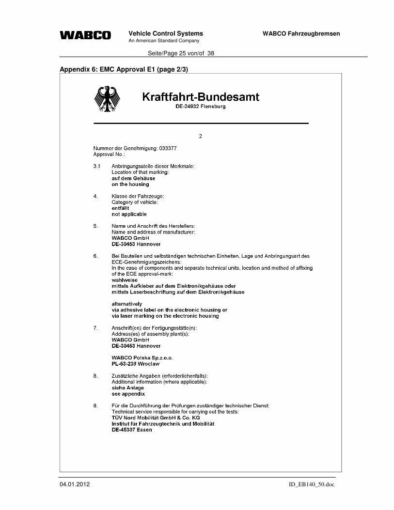
Appendix 6: EMC Approval E1 (page 1/3) 24
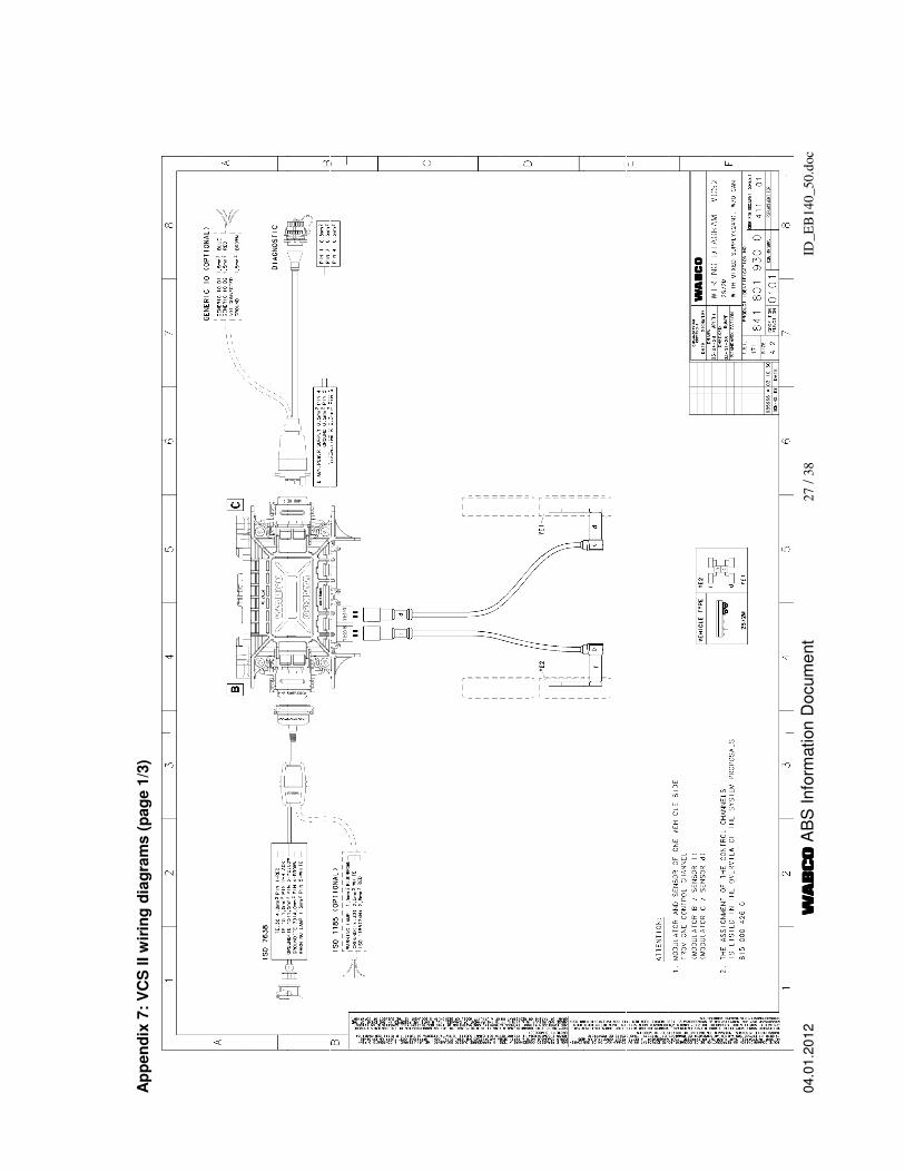
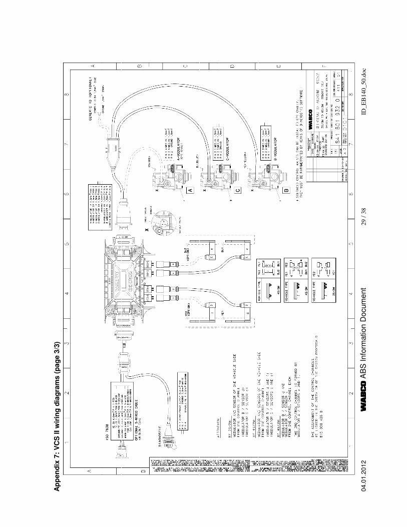
Appendix 7: VCS II wiring diagrams (page 1/3) 27
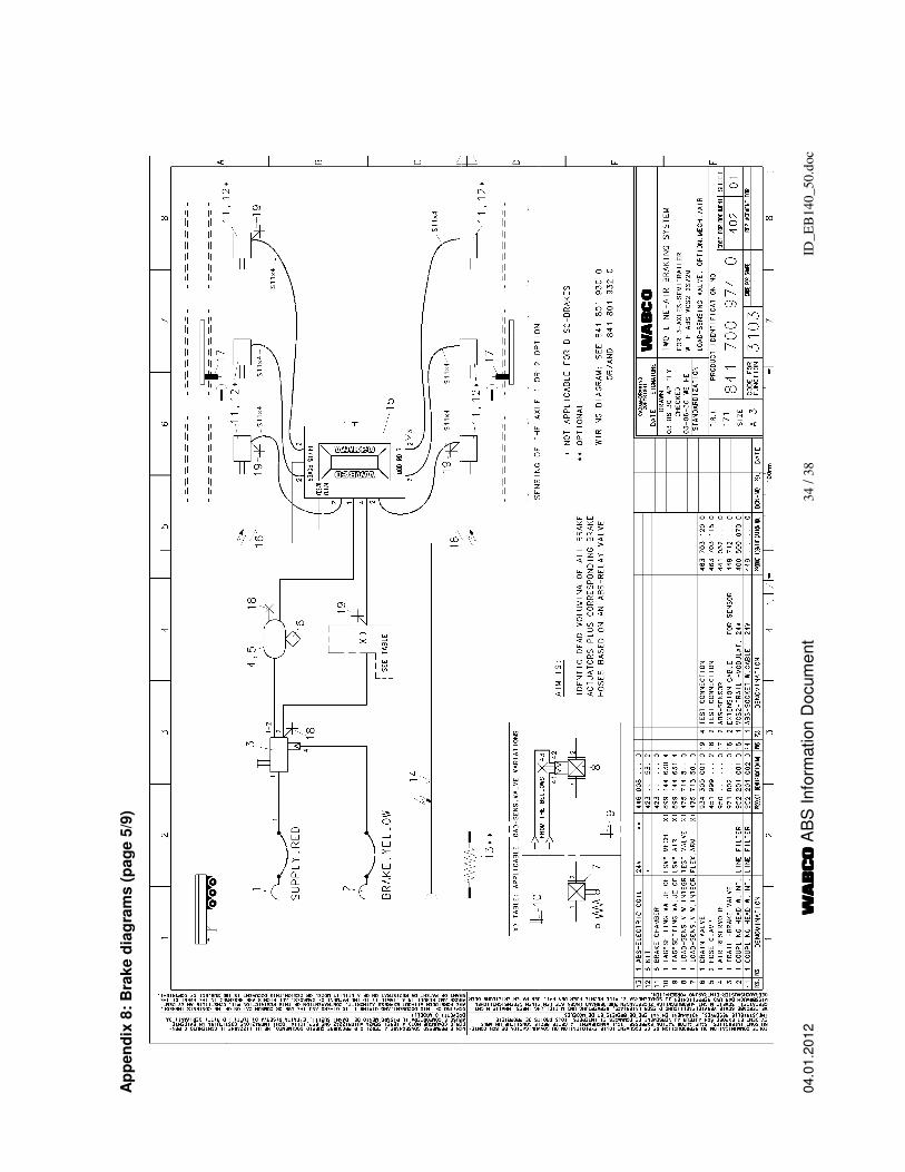
Appendix 8: Brake diagrams (page 1/9) 30
Vehicle Control Systems An American Standard Company
Seite/Page 3 von/of 38
WABCO Fahrzeugbremsen
04.01.2012 ID_EB140_50.doc
1 General The information contained in this document is used for the type approval of the prescribed anti-lock system. This information document has been compiled in accordance with the provisions defined within Annex XIV of Directive 71/320/EEC and Annex 19 of ECE Regulation 13/10 including Supplement 3.
1.1 Name of manufacturer
WABCO Vehicle Control Systems Am Lindener Hafen 21 D-30453 Hannover Germany
1.2 System name
Vario Compact Trailer ABS 2nd Generation (VCS II)
1.3 System variations
Standard power supply is 24 Volts, but also 12 Volt versions are available.
1.4 System configurations
2S/2M: two sensors and two modulators 4S/2M: four sensors and two modulators 4S/3M: four sensors and three modulators
Note: The two modulators with side by side control can be fitted as an integrated unit with the Vario Compact ABS ECU (“Integrated version”) or as separate components (“Non integrated version”), see also Appendix 1 and Appendix 4.
1.5 Explanation of the basic function and philosophy of the system
The Vario Compact ABS is installed as an ”add-on”-system in line with the service braking system. The sensors fitted to the wheels are inductive wheel speed sensors generating an electrical signal proportional to its wheel’s speed. The electronic control unit processes these signals into logical quantities for controlling the braking pressure via the modulators according to load and road conditions. In case of a locking tendency the brake cylinder pressure of the corresponding wheel will be released, kept constant during expected or measured wheel re-acceleration and is increased stepwise after re-acceleration to start the ABS-cycle again if the brake force is still too high for actual friction. The electrical system monitors itself. In the event of a fault, any parts found to be defective are selectively switched off, and the warning facility is actuated. Even in the
Vehicle Control Systems An American Standard Company
Seite/Page 4 von/of 38
WABCO Fahrzeugbremsen
04.01.2012 ID_EB140_50.doc
event of the whole system is being switched off, the function of the braking system covered by the ABS is maintained (although without ABS control). Correct electrical/electronic functioning of the ABS is indicated by a warning facility in the driver’s cab of the towing vehicle, or a warning light on the headboard of the trailer.
2 Applications
2.1 List of trailer types and ABS configurations for which approval is required
The Vario Compact ABS applies to semi-trailers, central axle trailers or drawbar trailers of category O3 and O4 with air braking systems according to the Framework Directive 70/156/EEC and according to annex 7 of the "Consolidated Resolution on the Construction of Vehicles (R.E.3)" respectively.
No. of axles
2S/2M 4S/2M 4S/3M
1 x - -
2 x x x semi-trailer
3 x x x
1 x - -
2 x x x central-axle trailer
3 x x x
2 - - x full trailer
3 - - x
The running gear can have mechanical, air or rubber suspension. Depending on the specific requirements of the respective trailer special equipment may be fitted upstream of the modulator, e. g. automatic load sensing valve, reducing, pressure limiting or adapting valves. The braking system may be equipped with drum brakes or disc brakes. For sample brake diagrams see appendix 8.
2.2 Schematic diagrams of the system configurations
Appendix 1 shows possible configurations of sensors and modulators for the different trailers defined in section 2.1.
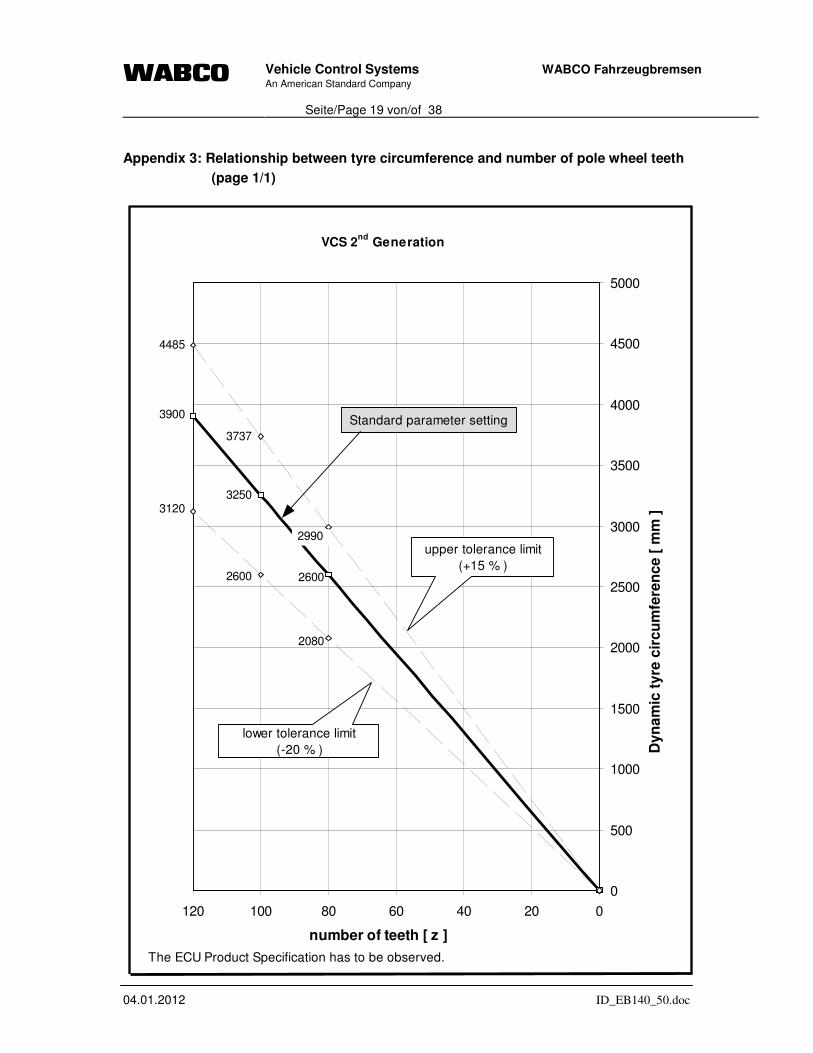
2.3 Relationship of tyre circumference to the resolution of the exciter
Case A: The exact tire is set by parameters: The ratio between tire circumference and pole wheel teeth number may range from 22 to 40.
Case B: The exact tire is not set by parameters: Reduced tolerances according to appendix 3 apply.
Vehicle Control Systems An American Standard Company
Seite/Page 5 von/of 38
WABCO Fahrzeugbremsen
04.01.2012 ID_EB140_50.doc
2.4 Tolerance on tyre circumference between one axle and another fitted with the same exciter
The inter wheel variations of rolling circumference must not exceed a value of 6,5 %. Otherwise the number of teeth on the pole wheels must be adjusted by setting corresponding parameters in the ECU.
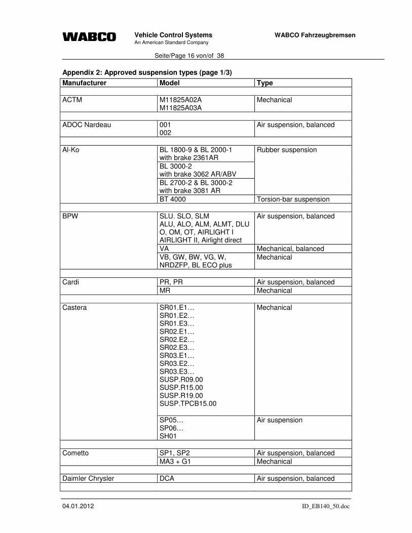
2.5 Scope of application with respect to suspension type
The Vario Compact ABS is applicable to trailers with mechanical, air or rubber suspension. Appendix 2 defines the specific suspension types by manufacturer for use.
2.6 Recommendations on differential brake input torque in relation to the ABS configuration and trailer bogie
For multiple-axle applications an almost identical utilization of friction of these axles is required. If all of the wheels are not fitted with sensors, the axle(s) which usually lock(s) first must be equipped with sensors. Multiple-axle applications having only static axle load proportioning must be equipped in that way that the wheels of all axles reach their locking point simultaneously and that one wheel directly controlled - does not control more than two other wheels or - in the case of central axle trailers does not indirectly control more than one wheel or one axle Differentials on brake input torque are admissible for all anti-lock configurations within a range of 20 %.
2.6.1 Test data of energy consumption - worst case loading
2.6.1.1 Annex XIV of Directive 71/320/EEC
To determine the axle load that produce a worse case energy consumption tests were carried out according to paragraph 6.1 of annex X of 71/320/EEC by varying the axle
loads. Within a range of ±10.000 N of the worst case the energy consumption for different ABS configurations have been determined. During all energy consumption tests the load sensing valve was in a fully laden position. Automatic slack adjusters (if installed) were out of operation, unless the vehicle with disc brakes (due to the design of this brake type). The following table represents the data of the energy consumption tests. It shows the supply pressure after ABS control of 15 sec and five additional applications. (The results are different for O3- and O4-vehicles).
Vehicle Control Systems An American Standard Company
Seite/Page 6 von/of 38
WABCO Fahrzeugbremsen
04.01.2012 ID_EB140_50.doc
2.6.1.2 Annex 19 of ECE-Regulation No. 13
With respect to the procedure of Annex 19 of ECE-R13 it is required (see paragraph 5.4.1.2.1) that the trailer(s) to be tested shall be loaded so that the axle load is 2.500 kg or 25 per cent of the permissible axle load whichever is the lower.
2.6.1.3 Equivalent static brake applications
Paragraph 6.2.1.2 of Annex XIV of Directive 71/320/EEC and paragraph 7.3.1.4 of Annex 19 of ECE-Regulation No. 13 define a verification procedure that after ne
applications (ne = number of equivalent static brake applications) the pressure in the
operating circuit is sufficient to provide a total braking force at the periphery of the wheels equal to not less than 22.5 per cent of the maximum stationary wheel load and without causing automatic application of any braking system not under the control of the anti-lock braking system.
In respect to the ABS components the result of this static “depletion test” is dependent on the air consumption during the respective brake applications.
The air consumption during this defined procedure with upgraded VCS II version is equal or less compared with the previous VCS version (VCS I).
Thus, depletion tests carried out within the approval homologation for the old version can be also used for the assessment within the approval homologation for the new system.
Vehicle Control Systems An American Standard Company
Seite/Page 7 von/of 38
WABCO Fahrzeugbremsen
04.01.2012 ID_EB140_50.doc
2.7 Additional information to the application of the anti-lock braking system
Each electronic control unit has a standard parameter setting depending on the WABCO part number and identification. Any defect can therefore be displayed for any specific system. The connection of an ECU, with its parameters set correspondingly, to a system arrangement is indicated by the warning facility staying on, and a specific error message.
3 Component description
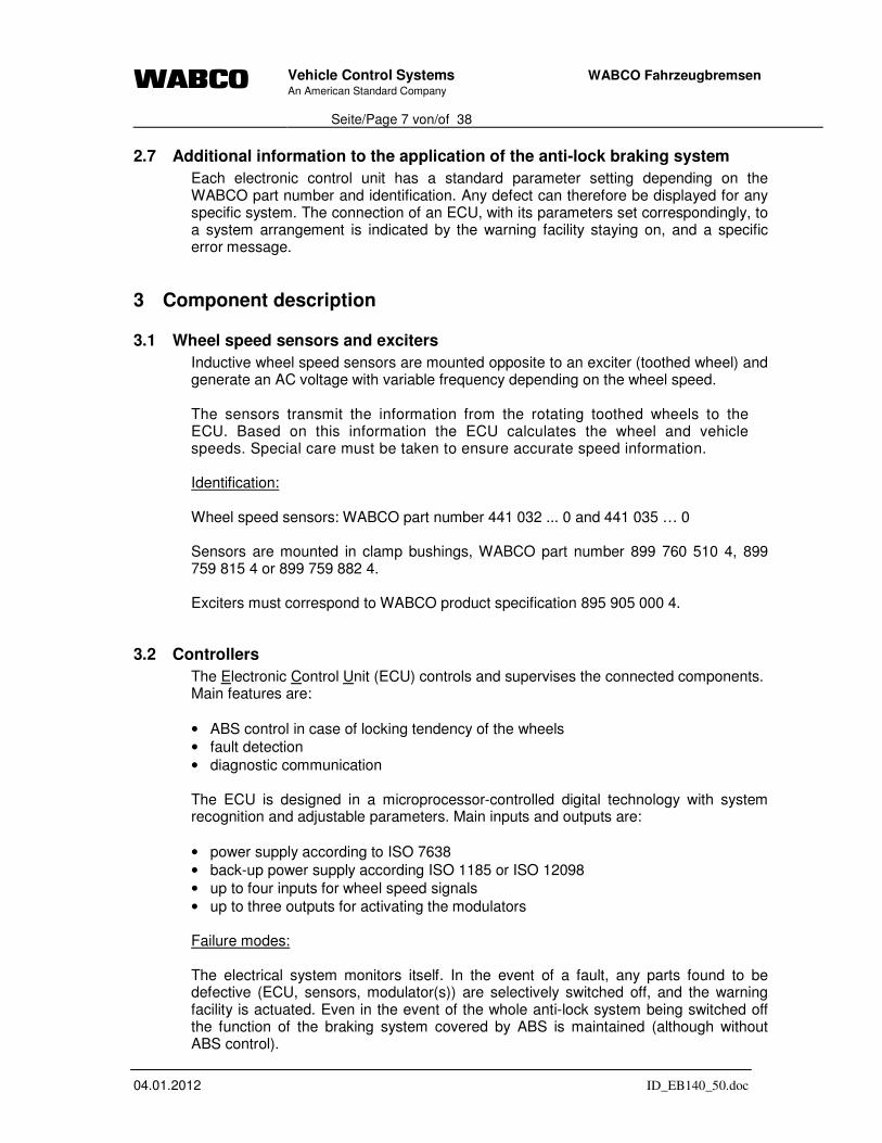
3.1 Wheel speed sensors and exciters
Inductive wheel speed sensors are mounted opposite to an exciter (toothed wheel) and generate an AC voltage with variable frequency depending on the wheel speed. The sensors transmit the information from the rotating toothed wheels to the ECU. Based on this information the ECU calculates the wheel and vehicle speeds. Special care must be taken to ensure accurate speed information. Identification: Wheel speed sensors: WABCO part number 441 032 ... 0 and 441 035 … 0 Sensors are mounted in clamp bushings, WABCO part number 899 760 510 4, 899 759 815 4 or 899 759 882 4. Exciters must correspond to WABCO product specification 895 905 000 4.
3.2 Controllers
The Electronic Control Unit (ECU) controls and supervises the connected components. Main features are:
• ABS control in case of locking tendency of the wheels
• fault detection
• diagnostic communication The ECU is designed in a microprocessor-controlled digital technology with system recognition and adjustable parameters. Main inputs and outputs are:
• power supply according to ISO 7638
• back-up power supply according ISO 1185 or ISO 12098
• up to four inputs for wheel speed signals
• up to three outputs for activating the modulators Failure modes: The electrical system monitors itself. In the event of a fault, any parts found to be defective (ECU, sensors, modulator(s)) are selectively switched off, and the warning facility is actuated. Even in the event of the whole anti-lock system being switched off the function of the braking system covered by ABS is maintained (although without ABS control).
Vehicle Control Systems An American Standard Company
Seite/Page 8 von/of 38
WABCO Fahrzeugbremsen
04.01.2012 ID_EB140_50.doc
Correct electrical/electronic function of the ABS is indicated by a warning facility in the drivers cab in the towing vehicle (via pin 5 of the electrical connector conforming to ISO 7638, according to the provisions of ECE-Regulation 13/10, section 5.2.1.29) or a warning light on the headboard of the trailer. Identification: Electronic Control Unit: WABCO part numbers 446 108 085 0 to 446 108 090 0 ECU/valve units: WABCO part numbers 400 500 070 0 to 400 500 090 0 Additional features:
• Generic Input/Output functionality
• tractor/trailer communication interface according ISO 11992
• diagnostic interface according to ISO 14230 (KWP2000)
• blink code
• automatic recognition of lift axles
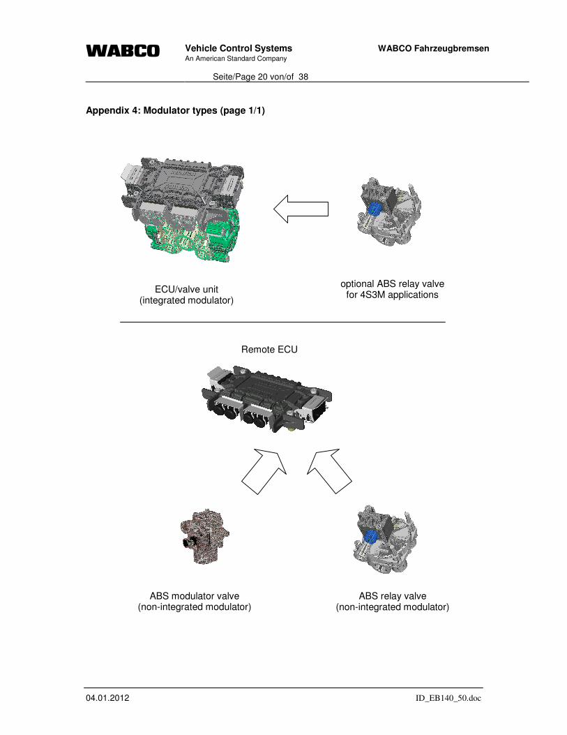
3.3 Modulators
Standard applications use the ECU/valve unit with an integrated 2-channel relay modulator. In case of 4S3M configurations or using the separate ECU external modulators as the ABS relay valve or the ABS solenoid control valve are employed. The ABS modulator valve serves the purpose of holding the pressure or venting the brake chambers. This is being done independently of the pressure that is transmitted by the brake valve of the trailer. Several types of modulators can be used (please also refer to appendix 4): ABS Relay Valve Electrically driven relay valves -both single or horizontally opposed relay valves- with the functions of:
• holding pressure (solenoid EV activated)
• reducing pressure (solenoid AV activated)
• increasing pressure (no solenoid active)
During a brake application without ABS active due to high friction surface, the
device operates as a relay valve; pressure that is put in the relay valve, is not
influenced by the valve. WABCO part numbers: 472 195 0.. 0 For limitations of application regarding volume of brake chamber etc. refer to the WABCO product specification of the valve. ABS Solenoid Control Valve Electrically controlled modulators with the functions of:
• holding pressure (solenoid EV activated)
Vehicle Control Systems An American Standard Company
Seite/Page 9 von/of 38
WABCO Fahrzeugbremsen
04.01.2012 ID_EB140_50.doc
• reducing pressure (solenoid EV and AV activated)
• increasing pressure (no solenoid active)
During a brake application without ABS active due to high friction surface, the
device has no function; pressure that is put in the valve, is not influenced by the
valve. WABCO part numbers: 472 195 0.. 0 For limitations of application regarding volume of brake chamber etc. refer to the WABCO product specification of the valve. Select Low Valve (SLV) Double Cut Off Valve (in combination with an additional relay valve, if necessary) to control self-steering axles in 2S/2M+SLV systems. Identification: Select Low Valve WABCO part numbers: 434 500 00. 0 Relay valve WABCO part numbers: 973 001 ... 0 973 011 ... 0
3.4 Electrical Equipment
The circuit diagrams in appendix 7 show the connection of all external components (power supply, sensors, modulators). They are connected via cables with moulded connectors, which fulfil GGVS resp. ADR requirements. Powering methods - Permanent power supply via the connector according to ISO 7638-1997 (5 or 7-pin)
Part 1 (24 V) or to ISO 7638-1985 (5-pin) (24 V).
- Permanent power supply via the connector according to ISO 7638-1997 (5 or 7-pin) Part 2 (12 V) or to ISO 7638-1985 (5-pin) (12 V).
In the event of ISO 7638 power supply failure to maintain trailer stability during braking: - Intermittent power supply via the connector according to ISO 1185 or ISO 12098 Warning lamp sequence The ECU can perform two different warning lamp sequences. The sequences work according to the provisions of ECE-Regulation 13/10, section 5.2.1.29 and fullfil the prescribed requirements of paragraphs 4.1.1 and 4.1.2 (including footnote 3) of Annex X of Directive 71/320/EEC. They can be changed by parameter setting. 1st Option:
Vehicle Control Systems An American Standard Company
Seite/Page 10 von/of 38
WABCO Fahrzeugbremsen
04.01.2012 ID_EB140_50.doc
When the vehicle is stationary:
• warning facility comes on after the power supply is switched on
• if no current error is detected, the warning facility is switched off after app. 2 seconds.
• if during prior driving a sensor or air gap fault was detected, the warning facility is
not turned off until v ≥ 7 k.p.h. (provided there is no current error present)
When the vehicle is moving at v ≥ 7 k.p.h.:
• Warning facility comes on or stays on if an error is detected 2nd Option: When the vehicle is stationary:
• warning facility comes on after the power supply is switched on
• if no current error is detected the warning facility will go off after app. 2 seconds and
come on again after further 2 seconds. The warning facility is switched off after v ≥ 7 k.p.h.
• if, however, a current error has been detected, e.g. of the sensor/air gap fault, the warning facility will stay on permanently after power supply has been switched on.
3.5 Pneumatic circuits
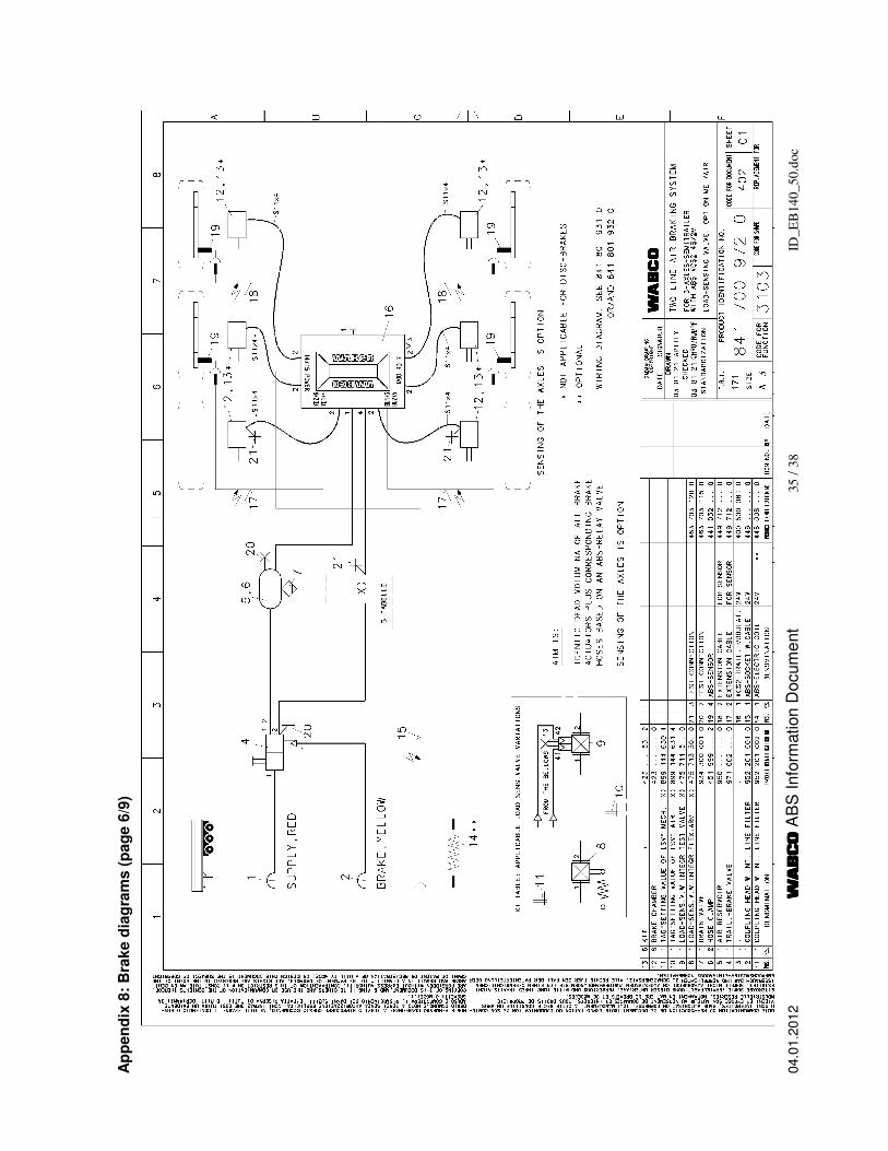
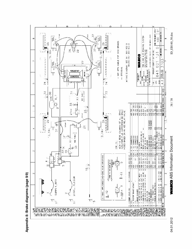
Sample brake diagrams for different trailers with standard air brakes are represented in appendix 8 (page 1 to 9): Page 1: 1-axle semi-trailer with 2S/2M Page 2: 2-axle central axle trailer with 2S/2M (diagonal axle regulation, DAR) Page 3: 2-axle semi-trailer with 2S/2M or 4S/2M Page 4: 2-axle semi-trailer with 4S/3M Page 5: 3-axle semi-trailer with 2S/2M Page 6: 3-axle semi-trailer with 4S/2M Page 7: 3-axle semi-trailer with 4S/3M Page 8: 2-axle trailer with 4S/3M Page 9: 3-axle trailer with 4S/3M Limitation on pipe/tube size and associated lengths: The length of the hoses between modulator valve and brake chambers should be as short as possible. tubes and hoses min. diameter max. length reservoir – ABS modulator see note see note ABS modulator – brake chamber
Note: The dimensions of the energy supply lines between reservoir and ABS modulator must allow to fulfil the response time requirements of Annex III of Directive 71/320/EEC and Annex 6 of ECE-Regulation No. 13 respectively.
Vehicle Control Systems An American Standard Company
Seite/Page 11 von/of 38
WABCO Fahrzeugbremsen
04.01.2012 ID_EB140_50.doc
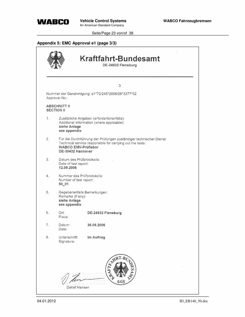
3.6 Electromagnetic Compatibility (EMC)
The Vario Compact ECU has been certified in compliance with the following regulations:
Council Directive 72/245/EEC relating to the radio interference (electromagnetic compatibility) of vehicles as last amended by Directive 2006/28/EC:
The type approval number is e1*72/245*2006/28*3377*02. The EMC approval report is enclosed in appendix 5 (3 pages).
ECE Regulation No. 10:
The type approval number is E1 10 R 033377. The EMC approval report is enclosed in appendix 6 (3 pages).
Further EMC tests have been carried out to verify sufficient immunity level equivalent to 100 V/m. Emission tests have been made to check out that there is no disturbance in radio frequency communication on vehicles.
Vehicle Control Systems An American Standard Company
Seite/Page 12 von/of 38
WABCO Fahrzeugbremsen
04.01.2012 ID_EB140_50.doc
4 List of Appendices
1 System configurations
2 Approved suspensions types
3 Relationship between tyre circumference and number of pole wheel teeth
4 Modulator types
5 EMC approval e1
6 EMC approval E1
7 VCS II wiring diagrams
8 Brake diagrams
Vehicle Control Systems An American Standard Company
Seite/Page 13 von/of 38
WABCO Fahrzeugbremsen
04.01.2012 ID_EB140_50.doc
Appendix 1: System Configurations (page 1/3)
ABS-Configurations for Semitrailer, Central Axle Trailer and Drawbar Trailer
Arrangement of control channels:(acc. to wiring diagrams841 801 930 0 to 841 801 933 0)
B / C
A
System axle: control logic:main axle IR / MSR(not liftable)steering axle MAR
(liftable)additional axle MSR(liftable)
Modula
tor
Sensors
c , d
e , f
e , f
System 2S/2M: L
Positively
Lift axles
Steering axles
ift axles shall not be sensed
All other systems: Lift axles can be sensed with ABS-sensors e and f.
steered axles have to be handled like rigid axles.
WABCO recommends that trailers with self steering axles shall be used with 4S/3M or 2S/2M+SLV configuration.
If 2S/2M or 4S/2M configurations are used, checks should be carried at the time of type approval of a trailer to ensure that no undue vibration or course deviation is observed. It is not possible to evaluate the reaction of all available steering axles in the case of anti-lock braking control.
LEGEND: Mounting Instructions for axle boogie types: = driving direction
= ABS modulators main axle (B/C)
= ABS modulator valve A
= select low valve (SLV)
B / C
B
C
Approved Modulator types:- Double ABS relay valve (integrated) - Separate ABS Relay valve (non-integrated)- ABS solenoid control valve (non-integrated)
Modulator types ABS solenoid control valves are not admissible at 2S2M and 4S2M configurations on 3 axle semi and centre axle trailers.
Vehicle Control Systems An American Standard Company
Seite/Page 14 von/of 38
WABCO Fahrzeugbremsen
04.01.2012 ID_EB140_50.doc
Appendix 1: System configurations (page 2/3)
+
2S / 2M 4S / 2M 4S / 3M Vehicle Type
Ce
ntr
e a
xle
tra
iler
+ S
em
itra
iler
Semi-trailer and Centre-axle Trailer
2S/2M-DAR
2S/2M+SLV
B
C
B
C
B
C
B
C
B
C
B
C
B
C
B
C
B
C
B
C
B
C
B
C
B
C
B
C
B
CA
B
CA
C
B
CA
B
CA
B
CA
B
CA
B
Vehicle Control Systems An American Standard Company
Seite/Page 15 von/of 38
WABCO Fahrzeugbremsen
04.01.2012 ID_EB140_50.doc
Appendix 1: System configurations (page 3/3) D
raw
ba
r T
raile
r
2S / 2M 4S / 2M 4S / 3M VEHICLE TYPE
Full Trailer
B
CA
B
CA
B
CA
A
B
CA
Vehicle Control Systems An American Standard Company
Seite/Page 16 von/of 38
WABCO Fahrzeugbremsen
04.01.2012 ID_EB140_50.doc
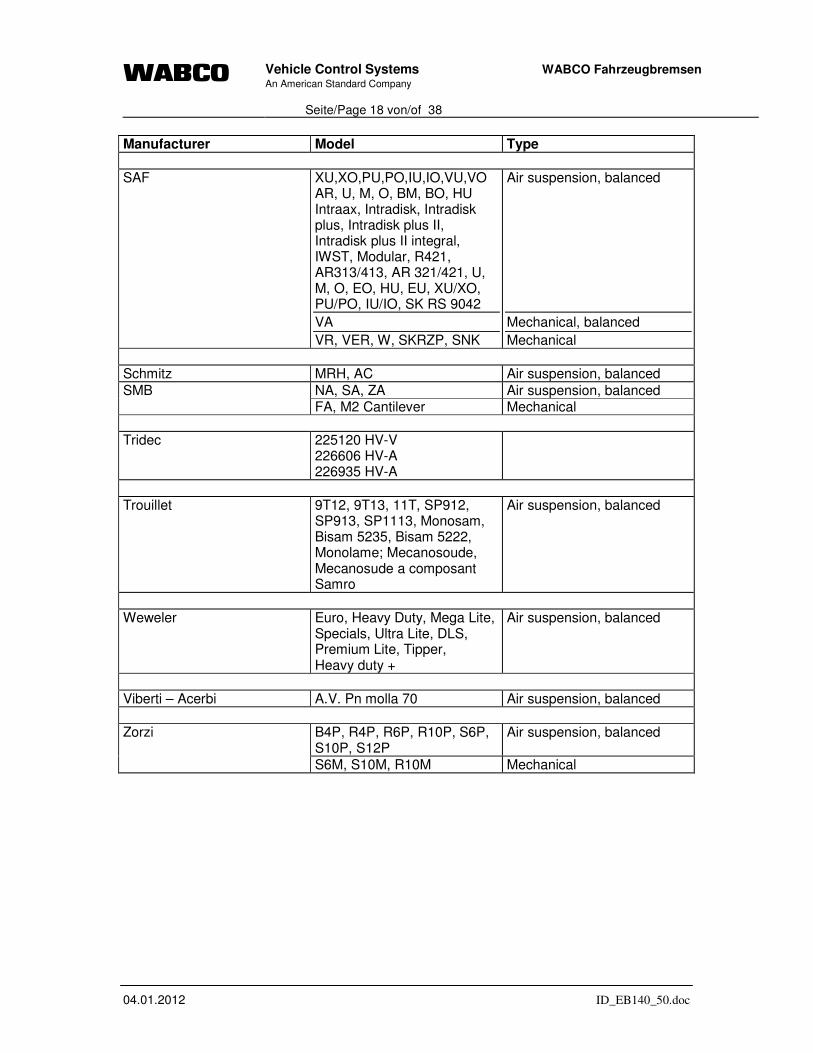
Appendix 2: Approved suspension types (page 1/3)
Manufacturer Model Type
ACTM M11825A02A M11825A03A
Mechanical
ADOC Nardeau 001 002
Air suspension, balanced
BL 1800-9 & BL 2000-1 with brake 2361AR
BL 3000-2 with brake 3062 AR/ABV
BL 2700-2 & BL 3000-2 with brake 3081 AR
Rubber suspension Al-Ko
BT 4000 Torsion-bar suspension
SLU. SLO, SLM ALU, ALO, ALM, ALMT, DLU O, OM, OT, AIRLIGHT I AIRLIGHT II, Airlight direct
Vehicle Control Systems An American Standard Company
Seite/Page 18 von/of 38
WABCO Fahrzeugbremsen
04.01.2012 ID_EB140_50.doc
Manufacturer Model Type
SAF XU,XO,PU,PO,IU,IO,VU,VO AR, U, M, O, BM, BO, HU Intraax, Intradisk, Intradisk plus, Intradisk plus II, Intradisk plus II integral, IWST, Modular, R421, AR313/413, AR 321/421, U, M, O, EO, HU, EU, XU/XO, PU/PO, IU/IO, SK RS 9042
VA
VR, VER, W, SKRZP, SNK
Air suspension, balanced
Mechanical, balanced
Mechanical
Schmitz MRH, AC Air suspension, balanced
NA, SA, ZA Air suspension, balanced SMB FA, M2 Cantilever Mechanical