Page 1
http://go.asme.org/HPVC
Vehicle Description Form
Human Powered Vehicle Challenge 2013 (Form 6)
Latin America: Univ Simon Bolivar, Caracas, Venezuela Feb 22-24 West: NASA Ames Research Ctr, Moffett Field, CA April 12-14 East: Ferris State University, Big Rapids, MI April 26-28
This required document for all teams is to be incorporated in to your Design Report. Please Observe Your
Due Dates
Vehicle Description
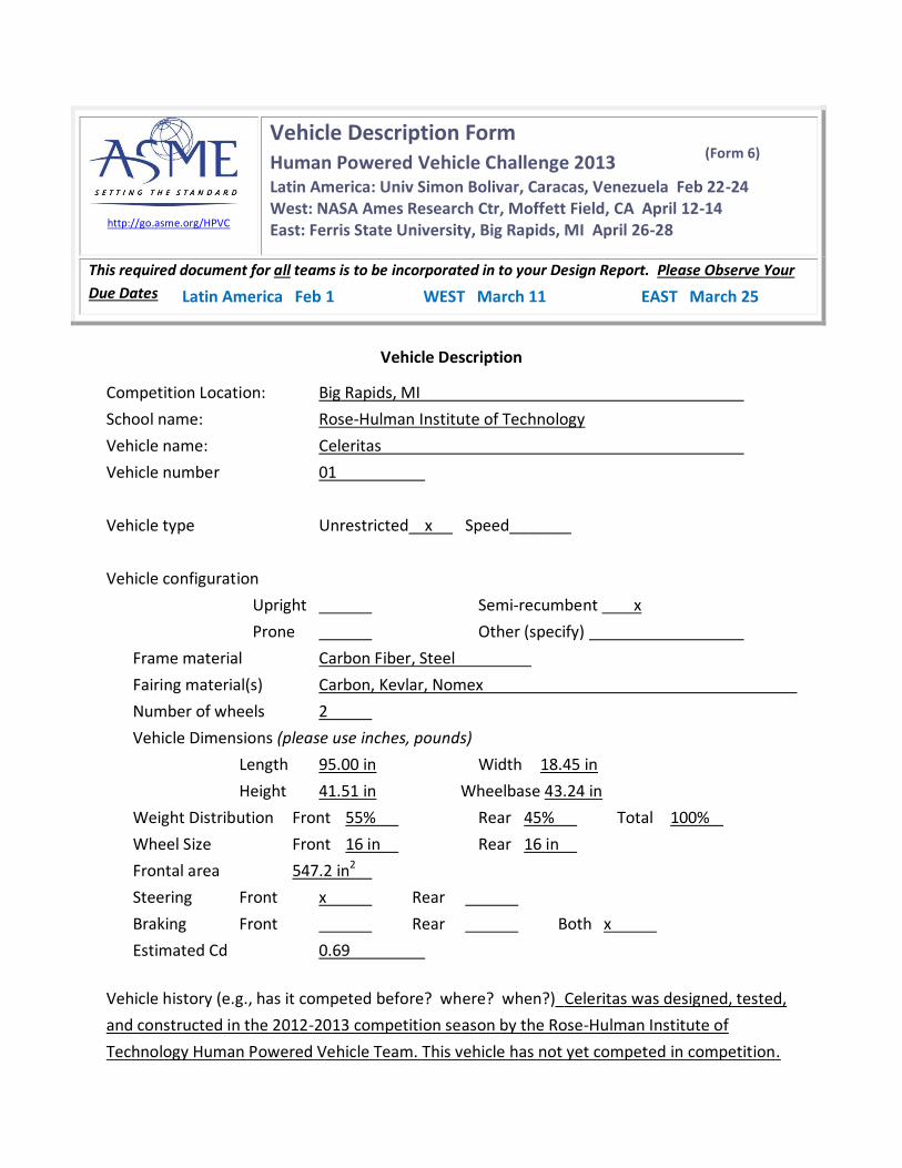
Competition Location: Big Rapids, MI
School name: Rose-Hulman Institute of Technology
Vehicle name: Celeritas
Vehicle number 01
Vehicle type Unrestricted x Speed_______
Vehicle configuration
Upright Semi-recumbent x
Prone Other (specify)
Frame material Carbon Fiber, Steel
Fairing material(s) Carbon, Kevlar, Nomex
Number of wheels 2
Vehicle Dimensions (please use inches, pounds)
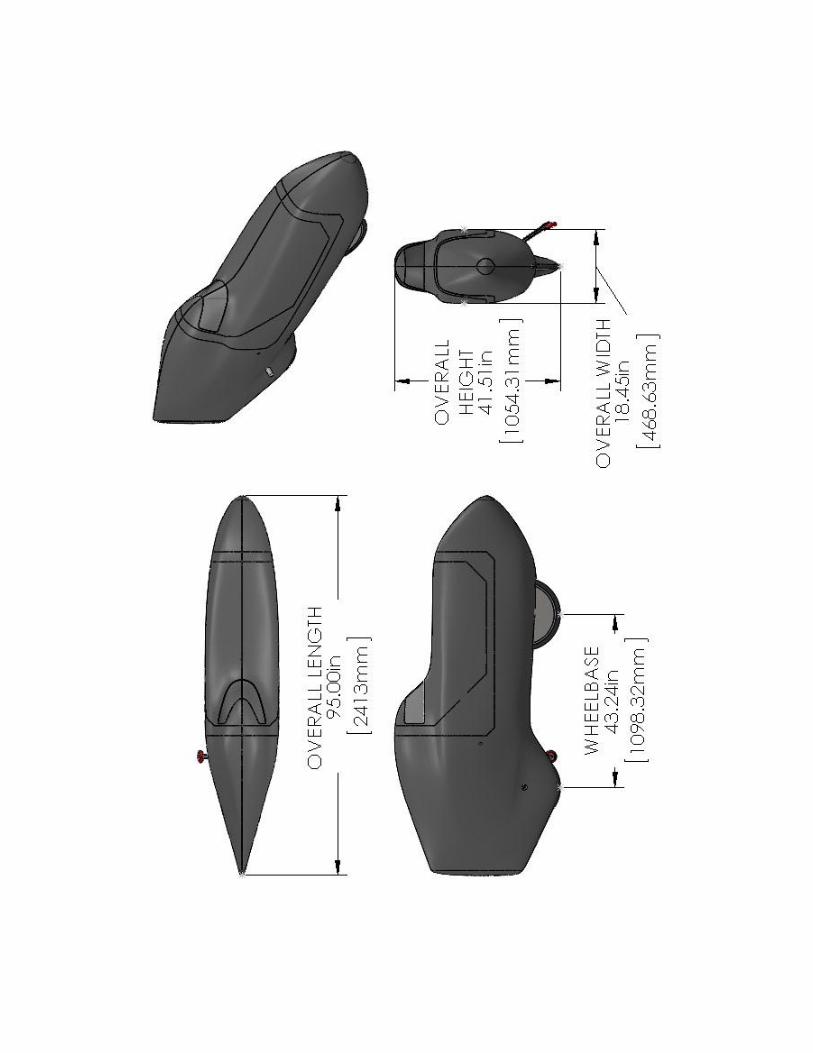
Length 95.00 in Width 18.45 in
Height 41.51 in Wheelbase 43.24 in
Weight Distribution Front 55% Rear 45% Total 100%
Wheel Size Front 16 in Rear 16 in
Frontal area 547.2 in2
Steering Front x Rear
Braking Front Rear Both x
Estimated Cd 0.69
Vehicle history (e.g., has it competed before? where? when?)_Celeritas was designed, tested,
and constructed in the 2012-2013 competition season by the Rose-Hulman Institute of
Technology Human Powered Vehicle Team. This vehicle has not yet competed in competition.
EAST March 25 WEST March 11 Latin America Feb 1
Page 2
2
Rose-Hulman Institute of Technology
2013 ASME East Coast HPV Challenge
Presents
Celeritas
Team Officers
Drew Robertson Patrick Woolfenden
Harrison Coons Simon Burns Matt Skorina
Team Members
Jeff Dovalovsky Ben Griffith
Crystal Hurtle Garrett Meyer Melissa Murray
Claire Stark Clay Dolesh
Travis Tatlock Louis Vaught
Patrick Woolfenden Elena Chong Homa Hariri Luke Brokl Jake Hiday
For more team information visit the team website at:
hpvt.rose-hulman.edu
Page 4
iii
Abstract
During the 2012-2013 competition season, the Rose-Hulman Human Powered Vehicle Team
designed and constructed Celeritas—a lightweight, efficient, and agile human-powered vehicle
that can safely and effectively be used for everyday transportation. The project’s scope included
all aspects of vehicle design and fabrication. The team conducted analysis, computational
modeling, and physical testing to demonstrate that Celeritas met the safety and feature
requirements of Rose-Hulman Institute of Technology, Human Powered Race America events,
and the ASME Human Powered Vehicle Challenge.
Within these requirements, the team designed Celeritas with the objectives of exceptional
performance, practicality, and safety. The vehicle is a semi-recumbent bicycle with a carbon
fiber structural fairing. The fairing weighs 25 lbf (111 N) and was the product of a six-piece
mold, which eliminated seaming. This design strengthened the fairing and removed 7 lbf (31.2
N) of weight.
The choice of standard bicycle components and sub-frame made of rectangular 4130 steel tubing
increased reparability and durability. The team designed Celeritas to have high stability at
expected riding speeds, an innovative and robust electronic landing gear, and an internally
geared hub (which allows shifting while stopped) to create easy, unassisted stops and starts.
These features combine with a grocery bag-sized storage space and a hazard flag to make
Celeritas a highly practical vehicle.
The team held rider safety paramount in the design of Celeritas. The vehicle boasts a forward
field of vision of 200 degrees and a protective layer of Kevlar to guard against penetrating
debris. Both its three-point safety harness and maximum top load on the roll bar tested at twice
ASME specifications. The team also introduced an innovative anti-lock braking system to guard
against loss of rider control. With robust and novel engineering, Celeritas advances the field of
human-powered vehicles.
i
Page 5
1 Design ........................................................... 1
Objective .................................................... 1 1.1
Background ................................................ 1 1.2
Prior Work.................................................. 1 1.3
Design Specifications .................................. 2 1.4
Concept Development & Selection 1.5
Methods .................................................................. 2
Organizational Timeline .............................. 3 1.6
Innovation .................................................. 4 1.7
1.7.1 Anti-Lock Braking System .......................... 4
1.7.2 Landing Gear Drive Mechanism .................. 5
1.7.3 Six-Piece Mold ........................................... 5
Frame Design ............................................. 6 1.8
Roll Bar ...................................................... 6 1.9
Landing Gear .............................................. 7 1.10
1.10.1 Slider...................................................... 7
1.10.2 Locking Mechanism ............................... 8
Drivetrain ................................................... 8 1.11
1.11.1 Low Q-Factor ......................................... 9
1.11.2 Internally Geared Hub............................. 9
Rear Hatch Magnetic Attachment ................ 9 1.12
Six-Piece Mold ......................................... 10 1.13
Practicality ............................................... 11 1.14
1.14.1 Fairing Openings .................................. 11
1.14.2 Storage ................................................. 11
1.14.3 Weather Conditions .............................. 12
1.14.4 Communication .................................... 12
2 Analysis ....................................................... 12
Rollover Protection System ....................... 12 2.1
Frame FEA ............................................... 14 2.2
Aerodynamic Analysis .............................. 16 2.3
Cost analysis ............................................. 17 2.4
Other Analysis .......................................... 18 2.5
2.5.1 Gearing .................................................... 18
2.5.2 Stability ................................................... 19
2.5.3 Turning Radius ......................................... 19
3 Testing ........................................................ 20
Rollover Protection System Testing .......... 20 3.1
Developmental Testing ............................. 20 3.2
3.2.1 Power Output Testing ............................... 20
3.2.2 Motion Capture ........................................ 21
3.2.3 Rib Attachment Method Testing ............... 21
3.2.4 Protective Layer Testing ........................... 22
3.2.5 Skid Testing ............................................. 23
3.2.6 Front Hatch Placement Testing ................. 23
3.2.7 Six-Piece Mold Testing ............................ 24
3.2.8 Gelcoat .................................................... 25
Performance Testing ................................. 25 3.3
3.3.1 Visibility .................................................. 25
4 Safety .......................................................... 26
Design for Safety...................................... 26 4.1
4.1.1 Roll Bar ................................................... 26
4.1.2 Windshield ............................................... 26
4.1.3 Seatbelt .................................................... 26
4.1.4 Safety of Manufacturing ........................... 26
Hazard Analysis ....................................... 27 4.2
5 Aesthetics .................................................... 27
6 Conclusion .................................................. 28
Comparison .............................................. 28 6.1
Evaluations .............................................. 28 6.2
Recommendations .................................... 29 6.3
Conclusion ............................................... 29 6.4
7 Appendices .................................................. 30
Appendix One .......................................... 30 7.1
Appendix Two ......................................... 33 7.2
Appendix Three........................................ 34 7.3
ii
Page 6
1
1 Design
Objective 1.1
The Rose-Hulman Human Powered Vehicle Team designed, analyzed, and constructed Celeritas
during the 2012-2013 competition season guided by the team’s mission statement:
The Rose-Hulman Human Powered Vehicle Team has the goals of furthering the
field of human-powered vehicles, creating a common library of knowledge
pertaining to their design and construction, developing innovative processes and
designs, and providing a positive learning and working environment for students.
The team designed Celeritas with the goal of creating a lightweight, efficient, and agile human-
powered vehicle that can safely and effectively be used for everyday transportation.
Background 1.2
Rising energy costs and increasing greenhouse gas levels have led companies and governments
worldwide to invest in sustainable and reliable forms of energy and transportation. In the past 10
years an increasing number of people have turned to bicycles for everyday transportation and
short trips around town [1]. Bicycles are an economic and efficient mode of transportation with
no fossil fuel consumption. Unfortunately, the unfaired upright bicycle has a low top speed and
offers little storage space and safety features compared to the average automobile.
The team sought to create a vehicle that surpasses the efficiency of an unfaired upright with the
convenience and safety of an automobile. Moving the rider to a recumbent position and adding
an aerodynamic fairing to the design allows for greater speed over longer distances while also
protecting the rider from their surroundings. A storage space behind the rider allows for further
practicality. With its increased efficiency, rider protection, and storage space, the faired
recumbent represents a niche in the sustainable transportation market that has not yet been
capitalized.
Prior Work 1.3
Over the past several years, the team has gained experience in the design and construction of
fared recumbent vehicles. Each year the team draws on past experience to improve the design
and create new and innovative features.
A small frontal area for Celeritas was obtained with the help of two design features from the
2009 Mark IV: a pass-through rear axle, and a narrow Q-factor (pedal to pedal width) [2].
From the 2010 Ragnarök, Celeritas incorporated an ergonomic seat and a flip-up tiller for ease of
ingress and egress. Wind condition analysis procedures developed for the 2010 Ragnarök were
also re-used to determine what crosswinds the vehicle should be designed to handle [3].
Celeritas was designed to closely fit riders with the help of a 3-D motion capture processing
program initially developed for the 2011 Helios [4].
Page 7
2
Many aspects of the 2012 Carƞot were also utilized in the design of Celeritas. The telescoping
landing gear system was improved with an innovative electronic actuation design. Celeritas
incorporates a redesigned structural fairing which retains the ribbed tub concept of the Carƞot but
offers improved clearances between the rider and the fairing. The team duplicated the success of
the snap fit hatches on Celeritas. Stability was analyzed using a MATLAB program developed
for the Carƞot. Improved placement of automotive trim, originally used on the Carƞot, provides
superior protection against skidding and wear. Similar to the Carƞot’s safety features, Celeritas
uses an integrated composite roll bar, which has been redesigned to allow improved seat
placement, and a lighter, more effective interior layer to protect riders if the fairing is damaged
[5].
Design Specifications 1.4
The team created a list of goals and constraints for Celeritas based on rules for the ASME
Human Powered Vehicle Competition (HPVC), Human Powered Race America (HPRA)
events, and restrictions imposed by Rose-Hulman.
Table 1: Constraints for Celeritas Design
ASME HPVC Rose-Hulman HPRA
15 ft (4.57 m) minimum turning radius Total cost of materials and
consumables of less than
$10,000
Rear-view mirrors
Braking from 15 to 0 mph (24.24 to 0
kph) in less than 20 ft (6.10 m)
Less than 8 ft (2.43 m) in length Independent and
redundant braking
system
Cargo area able to hold a reusable
grocery bag of dimensions: 15 x 13 x 8
in (38 x 33 x 20 cm)
No exposed carbon fiber near
rider
Rider safety harness Paint the vehicle with
traditional school colors (red,
white, and black)
Roll bar that can support 600 lbf (2.67
kN) top load with elastic deflection
less than 2 in (5.1 cm) and 300 lbf
(1.33kN) side load with elastic
deflection less than 1.5 in (3.8cm)
Concept Development & Selection Methods 1.5
The team used a House of Quality (HoQ) to balance the design considerations for Celeritas. The
HoQ shows needs ranked 1-5 as rows and metrics as columns. Improvement ratios (shown on the
far right) of greater than one indicate on which categories the team focused its efforts. The
correlation values between needs and metrics, relative importance values, and extent of influence
were assigned by team consensus.
Page 8
3
Figure 1: House of Quality for Celeritas Design
Based on these HoQ shown in Figure 1 above, areas of focus were determined to be the
coefficient of drag times the cross-sectional area, starting-stopping capabilities, acceleration, and
innovation. Improving these areas would have to come at the expense of other categories
analyzed in the HoQ, but the other categories had lower importance and could stand to stay the
same or decrease slightly. For example, improving the aerodynamics of the vehicle would come
at the expense of the rider comfort but the HoQ shows that rider comfort is of lower importance.
Organizational Timeline 1.6
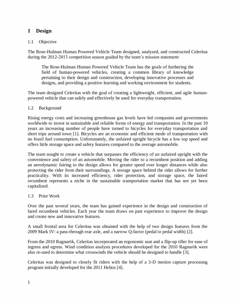
The Gantt chart in Figure 2 was used to make sure that the team could successfully complete a
vehicle meeting all of the design constraints and objectives within one academic year. The
beginning of the year was dedicated to designing Celeritas and introducing new members to the
team, while the second half of the year was spent constructing Celeritas and documenting work.
Page 9
4
Figure 2: Gantt Chart Scheduling the 2012-2013 Competition Season
Innovation 1.7
Following the mission statement, the team strives to create innovative solutions to problems
common to recumbent vehicles. For the 2012-2013 competition year, the team decided to focus
on preventing the brakes from locking, improving the landing gear system, and removing seams
from the final vehicle using a six-piece mold.
1.7.1 Anti-Lock Braking System
Due to the weight distribution in previous years’ vehicles, riders required significant experience
to avoid locking up the rear wheel while braking. The team rectified this through an anti-lock
braking system (ABS), similar to those used in automobiles. The ABS lowers the skill required
for operation of Celeritas and improves handling in adverse conditions, thus enhancing the safety
of the vehicle.
The ABS continually monitors the rotation of the rear wheel using an optical sensor to watch for
black strips painted on the rim of the wheel. When the rider pulls the rear brake lever, a sensor
detects how far the brake lever was depressed and a microcontroller relays a proportional signal
to a servo motor which actuates the rear disc brake. If at any time the optical sensor detects
wheel lock, the microcontroller reduces the braking force until the wheel turns.
Further details on the ABS can be found in Appendix One.
Page 10
5
1.7.2 Landing Gear Drive Mechanism
The landing gear system allows the rider to stop and start during the endurance race without
removing the canopy. To maintain the vehicle’s aerodynamic integrity the landing gear retracts
into the fairing similar to an airplane’s landing gear. In the 2012 Carηot Cycle, the actuation
mechanism for the landing gear was a manual pull cable which was prone to locking up and
disengaging without user input. To alleviate this problem in Celeritas, the team decided to pursue
an electric drive to control the actuation and retraction of the landing gear. This system increases
ease of use and reduces the possibility of user error.
Previous teams have pioneered electronically actuated landing gear; Celeritas uses an innovative
electronic design which is simpler and more robust. Celeritas replaces semiconductor devices,
sensors, and signal conditioning circuitry with a set of three mechanical switches. A schematic
for the landing gear circuit can be found in Figure 3.
Figure 3: Landing Gear Electronics Schematic (NC=Normally Closed, NO=Normally Open)
An actuation switch selects which direction the motor should turn. Once the landing gear has
fully deployed or retracted, one of the two limit switches will cut power to the motor depending
on its direction. This simple design is extremely efficient, reduces part costs and assembly time,
and is less vulnerable to damage by moisture or impact loading.
1.7.3 Six-Piece Mold
The team has traditionally made large composite parts in two halves and then seamed them
together. This often resulted in misaligned ribs, and ribs could not be placed along the centerline
of the vehicle. Seaming the halves of the 2012 Carƞot Cycle took six days of fabrication and
added a considerable amount of weight through extra carbon and epoxy. The seams were also
weak points prone to fatigue.
The team observed that epoxy does not wick through carbon fiber. This property allows one
section of a carbon fiber sheet to be cured during a layup and leave another section of the same
sheet uncured. Because dry carbon is left attached to the cured carbon, it can be used in later
processes to seamlessly lay up other parts of the vehicle.
In order to take advantage of this, the team required a mold that could be reconfigured. A six-
piece mold was used so that the top of the fairing could be laid up while leaving the bottom of
Actuation Switch
Limit Switches
Page 11
6
the fairing dry. The mold could then be reconfigured so that the bottom of the fairing could be
fabricated to produce a seamless vehicle. This process furthers the field of human powered
vehicles by providing a cost-effective solution to producing a seamless fairing with continuous
bottom ribs.
For further description on the development and functionality of the six-piece mold, see Section
1.12.
Frame Design 1.8
The Celeritas frame design is based on the same fundamental design as the 2012 Carηot Cycle.
The frame is a ribbed tub monocoque and a sub-frame to mount the front wheel and pedals.
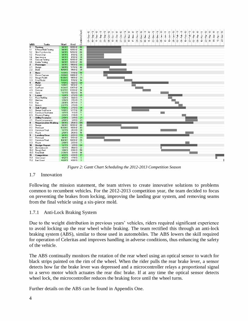
Ribs consisting of unidirectional carbon fiber around a Nomex core bear the majority of the load
in the fairing. The monocoque fairing design allows the team to use the aerodynamic skin as a
supplemental support structure. The carbon fiber ribs are positioned as shown in Figure 4 to
provide the optimal weight distribution. The use of composites results in a lightweight and
durable fairing.
Figure 4: Nomex Rib Layout
The Celeritas frame differs from the 2012 Carƞot Cycle in its use of a steel sub-frame, described
in Section 2.2, and ribs placed in the middle of vehicle. One of the benefits of the six-piece mold
is the ability to put supporting ribs in the middle of the vehicle, where they provide strength
without interfering with the rider. Previous manufacturing methods precluded placing ribs along
the centerline of the vehicle due to seaming requirements.
Roll Bar 1.9
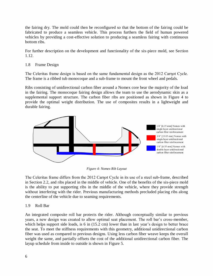
An integrated composite roll bar protects the rider. Although conceptually similar to previous
years, a new design was created to allow optimal seat placement. The roll bar’s cross-member,
which helps support side loads, is 6 in (15.2 cm) lower than in last year’s design to better brace
the seat. To meet the stiffness requirements with this geometry, additional unidirectional carbon
fiber was used as compared to previous designs. Using less carbon fiber weave keeps the overall
weight the same, and partially offsets the cost of the additional unidirectional carbon fiber. The
layup schedule from inside to outside is shown in Figure 5.
Page 12
7
Figure 5: Roll Bar Components
Landing Gear 1.10
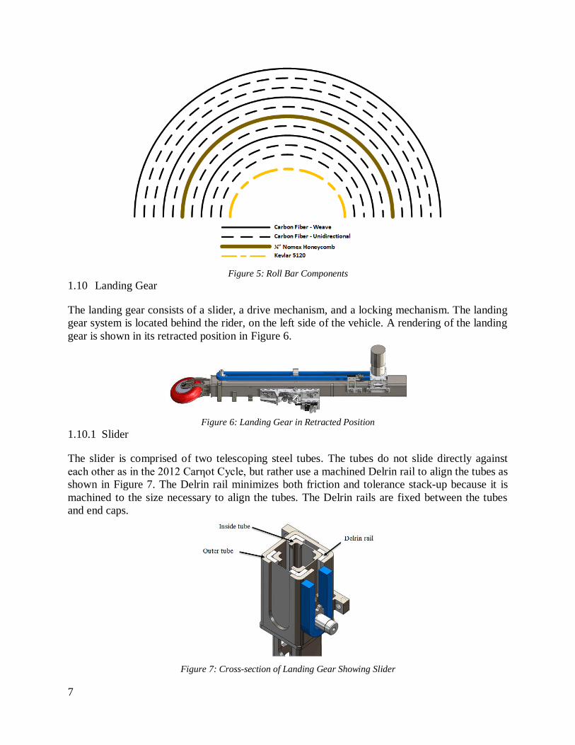
The landing gear consists of a slider, a drive mechanism, and a locking mechanism. The landing
gear system is located behind the rider, on the left side of the vehicle. A rendering of the landing
gear is shown in its retracted position in Figure 6.
Figure 6: Landing Gear in Retracted Position
1.10.1 Slider
The slider is comprised of two telescoping steel tubes. The tubes do not slide directly against
each other as in the 2012 Carηot Cycle, but rather use a machined Delrin rail to align the tubes as
shown in Figure 7. The Delrin rail minimizes both friction and tolerance stack-up because it is
machined to the size necessary to align the tubes. The Delrin rails are fixed between the tubes
and end caps.
Figure 7: Cross-section of Landing Gear Showing Slider
Page 13
8
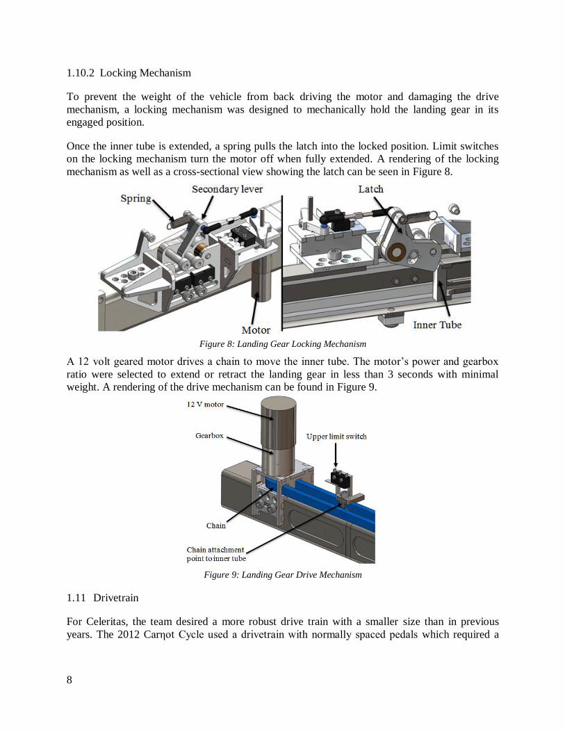
1.10.2 Locking Mechanism
To prevent the weight of the vehicle from back driving the motor and damaging the drive
mechanism, a locking mechanism was designed to mechanically hold the landing gear in its
engaged position.
Once the inner tube is extended, a spring pulls the latch into the locked position. Limit switches
on the locking mechanism turn the motor off when fully extended. A rendering of the locking
mechanism as well as a cross-sectional view showing the latch can be seen in Figure 8.
Figure 8: Landing Gear Locking Mechanism
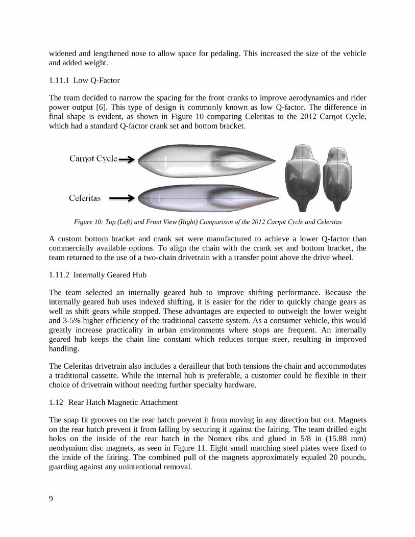
A 12 volt geared motor drives a chain to move the inner tube. The motor’s power and gearbox
ratio were selected to extend or retract the landing gear in less than 3 seconds with minimal
weight. A rendering of the drive mechanism can be found in Figure 9.
Figure 9: Landing Gear Drive Mechanism
Drivetrain 1.11
For Celeritas, the team desired a more robust drive train with a smaller size than in previous
years. The 2012 Carηot Cycle used a drivetrain with normally spaced pedals which required a
Page 14
9
widened and lengthened nose to allow space for pedaling. This increased the size of the vehicle
and added weight.
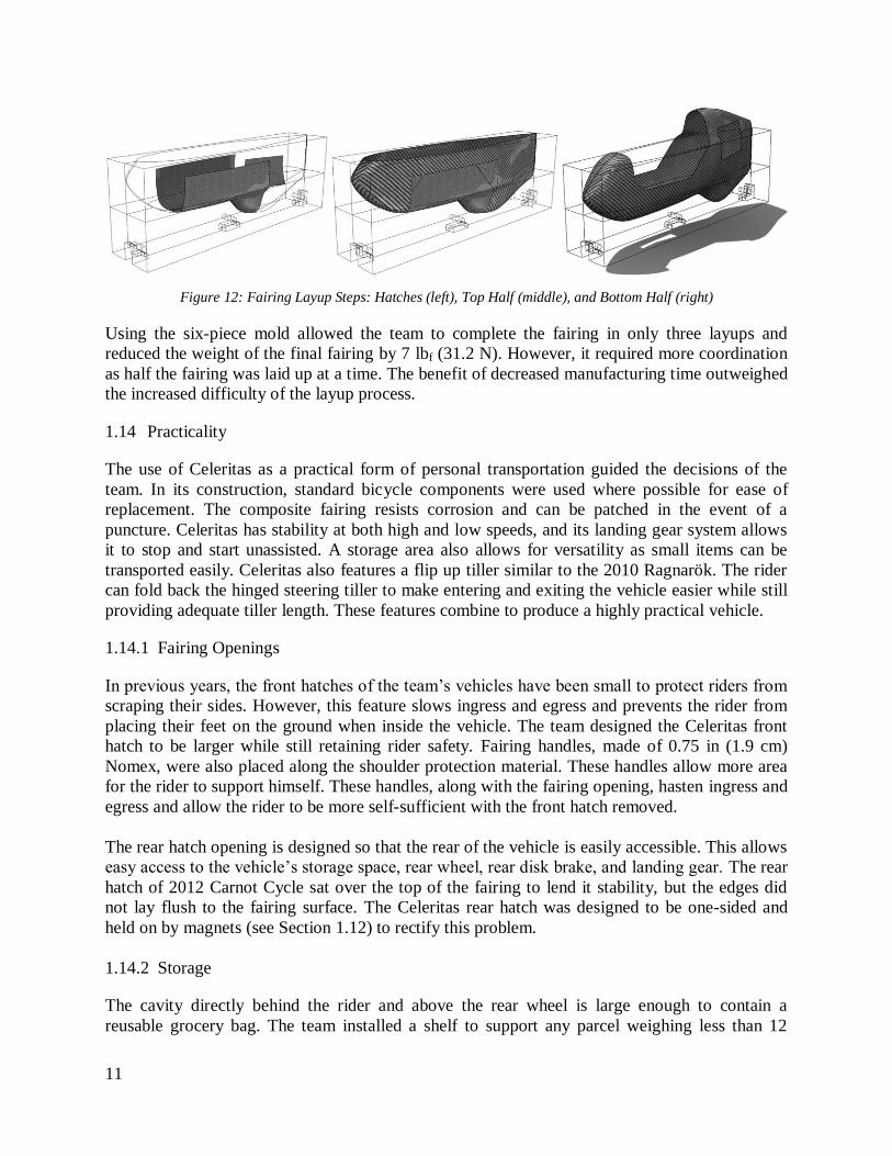
1.11.1 Low Q-Factor
The team decided to narrow the spacing for the front cranks to improve aerodynamics and rider
power output [6]. This type of design is commonly known as low Q-factor. The difference in
final shape is evident, as shown in Figure 10 comparing Celeritas to the 2012 Carηot Cycle,
which had a standard Q-factor crank set and bottom bracket.
Figure 10: Top (Left) and Front View (Right) Comparison of the 2012 Carηot Cycle and Celeritas
A custom bottom bracket and crank set were manufactured to achieve a lower Q-factor than
commercially available options. To align the chain with the crank set and bottom bracket, the
team returned to the use of a two-chain drivetrain with a transfer point above the drive wheel.
1.11.2 Internally Geared Hub
The team selected an internally geared hub to improve shifting performance. Because the
internally geared hub uses indexed shifting, it is easier for the rider to quickly change gears as
well as shift gears while stopped. These advantages are expected to outweigh the lower weight
and 3-5% higher efficiency of the traditional cassette system. As a consumer vehicle, this would
greatly increase practicality in urban environments where stops are frequent. An internally
geared hub keeps the chain line constant which reduces torque steer, resulting in improved
handling.
The Celeritas drivetrain also includes a derailleur that both tensions the chain and accommodates
a traditional cassette. While the internal hub is preferable, a customer could be flexible in their
choice of drivetrain without needing further specialty hardware.
Rear Hatch Magnetic Attachment 1.12
The snap fit grooves on the rear hatch prevent it from moving in any direction but out. Magnets
on the rear hatch prevent it from falling by securing it against the fairing. The team drilled eight
holes on the inside of the rear hatch in the Nomex ribs and glued in 5/8 in (15.88 mm)
neodymium disc magnets, as seen in Figure 11. Eight small matching steel plates were fixed to
the inside of the fairing. The combined pull of the magnets approximately equaled 20 pounds,
guarding against any unintentional removal.
Page 15
10
Figure 11: Rear Hatch with Red Dots Marking Magnets (left) and Indented Magnets in a Nomex Rib (right)
Six-Piece Mold 1.13
The team investigated alternative methods to manufacture the fairing to avoid seaming. One
required expanding a highly pressurized bladder into the mold cavity. The team’s previous molds
would be incapable of handling this. Metal molds, which would solve this problem, are not cost
effective for one-off production.
In previous years, the team observed that unintended dry spots could occur in the laminate if the
reinforcing fibers were not fully impregnated before being placed in the mold, because epoxy
cures before it can wick through the fabric. Consequently, applying epoxy to only one area of a
reinforcing sheet allows that area to cure in a shape, while the rest of the fabric remains
formable. In doing this, a continuous piece of fabric can be laid up in multiple stages.The team
laid up Celeritas in two halves using this technique to create a seamless fairing. The routed mold
was cut into six pieces to utilize this method.
The first step of this process was to create the hatches that the rider uses to get into the vehicle
and access the rear wheel. The top half of the mold was put together and placed in a box to hold
them in position. The same configuration was used to lay up the top half of the fairing; epoxy
was impregnated into the top half leaving excess carbon for the rest of the vehicle dry.
The lower half of the six-piece mold was placed into the box for the next layup, and the fairing
was placed in the mold. The dry carbon from the first layup was then saturated with epoxy. After
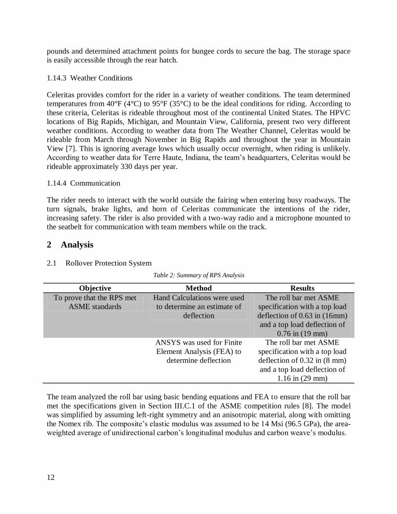
curing, a full, seamless, monocoque faring was left as shown in Figure 12. The lower half of
these six-piece mold was placed into the box for the next layup, and the fairing was placed in the
mold. The dry carbon from the first layup was then saturated with epoxy. After curing, a full,
seamless, monocoque faring was left as shown in Figure 12.
Page 16
11
Figure 12: Fairing Layup Steps: Hatches (left), Top Half (middle), and Bottom Half (right)
Using the six-piece mold allowed the team to complete the fairing in only three layups and
reduced the weight of the final fairing by 7 lbf (31.2 N). However, it required more coordination
as half the fairing was laid up at a time. The benefit of decreased manufacturing time outweighed
the increased difficulty of the layup process.
Practicality 1.14
The use of Celeritas as a practical form of personal transportation guided the decisions of the
team. In its construction, standard bicycle components were used where possible for ease of
replacement. The composite fairing resists corrosion and can be patched in the event of a
puncture. Celeritas has stability at both high and low speeds, and its landing gear system allows
it to stop and start unassisted. A storage area also allows for versatility as small items can be
transported easily. Celeritas also features a flip up tiller similar to the 2010 Ragnarök. The rider
can fold back the hinged steering tiller to make entering and exiting the vehicle easier while still
providing adequate tiller length. These features combine to produce a highly practical vehicle.
1.14.1 Fairing Openings
In previous years, the front hatches of the team’s vehicles have been small to protect riders from
scraping their sides. However, this feature slows ingress and egress and prevents the rider from
placing their feet on the ground when inside the vehicle. The team designed the Celeritas front
hatch to be larger while still retaining rider safety. Fairing handles, made of 0.75 in (1.9 cm)
Nomex, were also placed along the shoulder protection material. These handles allow more area
for the rider to support himself. These handles, along with the fairing opening, hasten ingress and
egress and allow the rider to be more self-sufficient with the front hatch removed.
The rear hatch opening is designed so that the rear of the vehicle is easily accessible. This allows
easy access to the vehicle’s storage space, rear wheel, rear disk brake, and landing gear. The rear
hatch of 2012 Carnot Cycle sat over the top of the fairing to lend it stability, but the edges did
not lay flush to the fairing surface. The Celeritas rear hatch was designed to be one-sided and
held on by magnets (see Section 1.12) to rectify this problem.
1.14.2 Storage
The cavity directly behind the rider and above the rear wheel is large enough to contain a
reusable grocery bag. The team installed a shelf to support any parcel weighing less than 12
Page 17
12
pounds and determined attachment points for bungee cords to secure the bag. The storage space
is easily accessible through the rear hatch.
1.14.3 Weather Conditions
Celeritas provides comfort for the rider in a variety of weather conditions. The team determined
temperatures from 40°F (4°C) to 95°F (35°C) to be the ideal conditions for riding. According to
these criteria, Celeritas is rideable throughout most of the continental United States. The HPVC
locations of Big Rapids, Michigan, and Mountain View, California, present two very different
weather conditions. According to weather data from The Weather Channel, Celeritas would be
rideable from March through November in Big Rapids and throughout the year in Mountain
View [7]. This is ignoring average lows which usually occur overnight, when riding is unlikely.
According to weather data for Terre Haute, Indiana, the team’s headquarters, Celeritas would be
rideable approximately 330 days per year.
1.14.4 Communication
The rider needs to interact with the world outside the fairing when entering busy roadways. The
turn signals, brake lights, and horn of Celeritas communicate the intentions of the rider,
increasing safety. The rider is also provided with a two-way radio and a microphone mounted to
the seatbelt for communication with team members while on the track.
2 Analysis
Rollover Protection System 2.1
Table 2: Summary of RPS Analysis
Objective Method Results
To prove that the RPS met
ASME standards
Hand Calculations were used
to determine an estimate of
deflection
The roll bar met ASME
specification with a top load
deflection of 0.63 in (16mm)
and a top load deflection of
0.76 in (19 mm)
ANSYS was used for Finite
Element Analysis (FEA) to
determine deflection
The roll bar met ASME
specification with a top load
deflection of 0.32 in (8 mm)
and a top load deflection of
1.16 in (29 mm)
The team analyzed the roll bar using basic bending equations and FEA to ensure that the roll bar
met the specifications given in Section III.C.1 of the ASME competition rules [8]. The model
was simplified by assuming left-right symmetry and an anisotropic material, along with omitting
the Nomex rib. The composite’s elastic modulus was assumed to be 14 Msi (96.5 GPa), the area-
weighted average of unidirectional carbon’s longitudinal modulus and carbon weave’s modulus.
Page 18
13
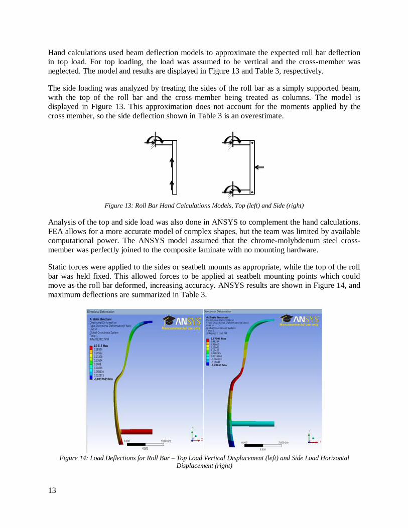
Hand calculations used beam deflection models to approximate the expected roll bar deflection
in top load. For top loading, the load was assumed to be vertical and the cross-member was
neglected. The model and results are displayed in Figure 13 and Table 3, respectively.
The side loading was analyzed by treating the sides of the roll bar as a simply supported beam,
with the top of the roll bar and the cross-member being treated as columns. The model is
displayed in Figure 13. This approximation does not account for the moments applied by the
cross member, so the side deflection shown in Table 3 is an overestimate.
Figure 13: Roll Bar Hand Calculations Models, Top (left) and Side (right)
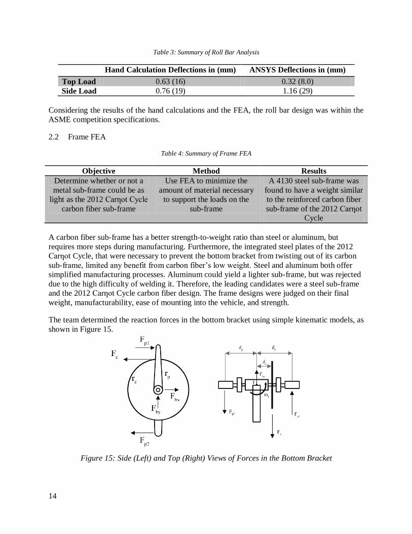
Analysis of the top and side load was also done in ANSYS to complement the hand calculations.
FEA allows for a more accurate model of complex shapes, but the team was limited by available
computational power. The ANSYS model assumed that the chrome-molybdenum steel cross-
member was perfectly joined to the composite laminate with no mounting hardware.
Static forces were applied to the sides or seatbelt mounts as appropriate, while the top of the roll
bar was held fixed. This allowed forces to be applied at seatbelt mounting points which could
move as the roll bar deformed, increasing accuracy. ANSYS results are shown in Figure 14, and
maximum deflections are summarized in Table 3.
Figure 14: Load Deflections for Roll Bar – Top Load Vertical Displacement (left) and Side Load Horizontal
Displacement (right)
Page 19
14
Table 3: Summary of Roll Bar Analysis
Hand Calculation Deflections in (mm) ANSYS Deflections in (mm)
Top Load 0.63 (16) 0.32 (8.0)
Side Load 0.76 (19) 1.16 (29)
Considering the results of the hand calculations and the FEA, the roll bar design was within the
ASME competition specifications.
Frame FEA 2.2
Table 4: Summary of Frame FEA
Objective Method Results
Determine whether or not a
metal sub-frame could be as
light as the 2012 Carƞot Cycle
carbon fiber sub-frame
Use FEA to minimize the
amount of material necessary
to support the loads on the
sub-frame
A 4130 steel sub-frame was
found to have a weight similar
to the reinforced carbon fiber
sub-frame of the 2012 Carƞot
Cycle
A carbon fiber sub-frame has a better strength-to-weight ratio than steel or aluminum, but
requires more steps during manufacturing. Furthermore, the integrated steel plates of the 2012
Carƞot Cycle, that were necessary to prevent the bottom bracket from twisting out of its carbon
sub-frame, limited any benefit from carbon fiber’s low weight. Steel and aluminum both offer
simplified manufacturing processes. Aluminum could yield a lighter sub-frame, but was rejected
due to the high difficulty of welding it. Therefore, the leading candidates were a steel sub-frame
and the 2012 Carƞot Cycle carbon fiber design. The frame designs were judged on their final
weight, manufacturability, ease of mounting into the vehicle, and strength.
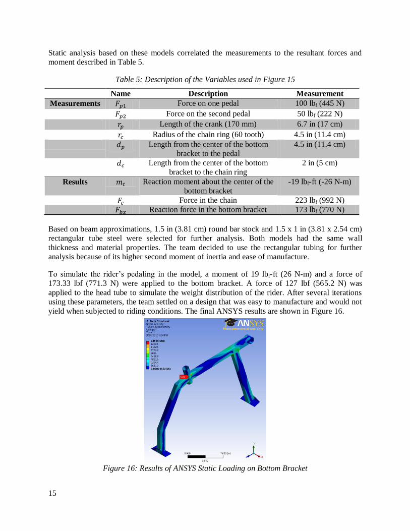
The team determined the reaction forces in the bottom bracket using simple kinematic models, as
shown in Figure 15.
Figure 15: Side (Left) and Top (Right) Views of Forces in the Bottom Bracket
Page 20
15
Static analysis based on these models correlated the measurements to the resultant forces and
moment described in Table 5.
Table 5: Description of the Variables used in Figure 15
Name Description Measurement
Measurements Force on one pedal 100 lbf (445 N)
Force on the second pedal 50 lbf (222 N)
Length of the crank (170 mm) 6.7 in (17 cm)
Radius of the chain ring (60 tooth) 4.5 in (11.4 cm)
Length from the center of the bottom
bracket to the pedal
4.5 in (11.4 cm)
Length from the center of the bottom
bracket to the chain ring
2 in (5 cm)
Results Reaction moment about the center of the
bottom bracket
-19 lbf-ft (-26 N-m)
Force in the chain 223 lbf (992 N)
Reaction force in the bottom bracket 173 lbf (770 N)
Based on beam approximations, 1.5 in (3.81 cm) round bar stock and 1.5 x 1 in (3.81 x 2.54 cm)
rectangular tube steel were selected for further analysis. Both models had the same wall
thickness and material properties. The team decided to use the rectangular tubing for further
analysis because of its higher second moment of inertia and ease of manufacture.
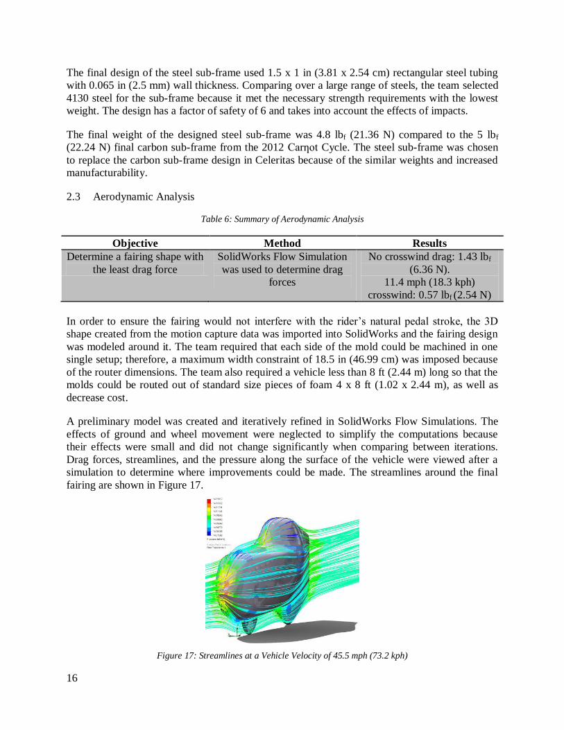
To simulate the rider’s pedaling in the model, a moment of 19 lbf-ft (26 N-m) and a force of
173.33 lbf (771.3 N) were applied to the bottom bracket. A force of 127 lbf (565.2 N) was
applied to the head tube to simulate the weight distribution of the rider. After several iterations
using these parameters, the team settled on a design that was easy to manufacture and would not
yield when subjected to riding conditions. The final ANSYS results are shown in Figure 16.
Figure 16: Results of ANSYS Static Loading on Bottom Bracket
Page 21
16
The final design of the steel sub-frame used 1.5 x 1 in (3.81 x 2.54 cm) rectangular steel tubing
with 0.065 in (2.5 mm) wall thickness. Comparing over a large range of steels, the team selected
4130 steel for the sub-frame because it met the necessary strength requirements with the lowest
weight. The design has a factor of safety of 6 and takes into account the effects of impacts.
The final weight of the designed steel sub-frame was 4.8 lbf (21.36 N) compared to the 5 lbf
(22.24 N) final carbon sub-frame from the 2012 Carƞot Cycle. The steel sub-frame was chosen
to replace the carbon sub-frame design in Celeritas because of the similar weights and increased
manufacturability.
Aerodynamic Analysis 2.3
Table 6: Summary of Aerodynamic Analysis
Objective Method Results
Determine a fairing shape with
the least drag force
SolidWorks Flow Simulation
was used to determine drag
forces
No crosswind drag: 1.43 lbf
(6.36 N).
11.4 mph (18.3 kph)
crosswind: 0.57 lbf (2.54 N)
In order to ensure the fairing would not interfere with the rider’s natural pedal stroke, the 3D
shape created from the motion capture data was imported into SolidWorks and the fairing design
was modeled around it. The team required that each side of the mold could be machined in one
single setup; therefore, a maximum width constraint of 18.5 in (46.99 cm) was imposed because
of the router dimensions. The team also required a vehicle less than 8 ft (2.44 m) long so that the
molds could be routed out of standard size pieces of foam 4 x 8 ft (1.02 x 2.44 m), as well as
decrease cost.
A preliminary model was created and iteratively refined in SolidWorks Flow Simulations. The
effects of ground and wheel movement were neglected to simplify the computations because
their effects were small and did not change significantly when comparing between iterations.
Drag forces, streamlines, and the pressure along the surface of the vehicle were viewed after a
simulation to determine where improvements could be made. The streamlines around the final
fairing are shown in Figure 17.
Figure 17: Streamlines at a Vehicle Velocity of 45.5 mph (73.2 kph)
Page 22
17
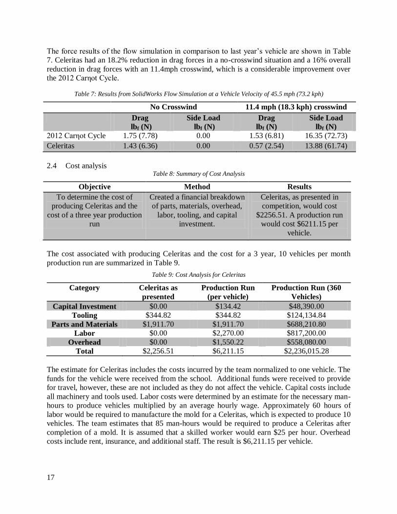
The force results of the flow simulation in comparison to last year’s vehicle are shown in Table
7. Celeritas had an 18.2% reduction in drag forces in a no-crosswind situation and a 16% overall
reduction in drag forces with an 11.4mph crosswind, which is a considerable improvement over
the 2012 Carηot Cycle.
Table 7: Results from SolidWorks Flow Simulation at a Vehicle Velocity of 45.5 mph (73.2 kph)
No Crosswind 11.4 mph (18.3 kph) crosswind
Drag
lbf (N)
Side Load
lbf (N)
Drag
lbf (N)
Side Load
lbf (N)
2012 Carηot Cycle 1.75 (7.78) 0.00 1.53 (6.81) 16.35 (72.73)
Celeritas 1.43 (6.36) 0.00 0.57 (2.54) 13.88 (61.74)
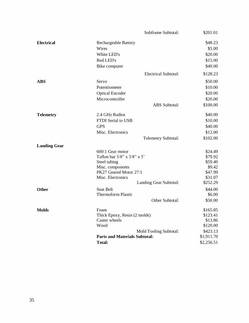
Cost analysis 2.4Table 8: Summary of Cost Analysis
Objective Method Results
To determine the cost of
producing Celeritas and the
cost of a three year production
run
Created a financial breakdown
of parts, materials, overhead,
labor, tooling, and capital
investment.
Celeritas, as presented in
competition, would cost
$2256.51. A production run
would cost $6211.15 per
vehicle.
The cost associated with producing Celeritas and the cost for a 3 year, 10 vehicles per month
production run are summarized in Table 9.
Table 9: Cost Analysis for Celeritas
Category Celeritas as
presented
Production Run
(per vehicle)
Production Run (360
Vehicles)
Capital Investment $0.00 $134.42 $48,390.00
Tooling $344.82 $344.82 $124,134.84
Parts and Materials $1,911.70 $1,911.70 $688,210.80
Labor $0.00 $2,270.00 $817,200.00
Overhead $0.00 $1,550.22 $558,080.00
Total $2,256.51 $6,211.15 $2,236,015.28
The estimate for Celeritas includes the costs incurred by the team normalized to one vehicle. The
funds for the vehicle were received from the school. Additional funds were received to provide
for travel, however, these are not included as they do not affect the vehicle. Capital costs include
all machinery and tools used. Labor costs were determined by an estimate for the necessary man-
hours to produce vehicles multiplied by an average hourly wage. Approximately 60 hours of
labor would be required to manufacture the mold for a Celeritas, which is expected to produce 10
vehicles. The team estimates that 85 man-hours would be required to produce a Celeritas after
completion of a mold. It is assumed that a skilled worker would earn $25 per hour. Overhead
costs include rent, insurance, and additional staff. The result is $6,211.15 per vehicle.
Page 23
18
A detailed analysis of the production run is included as Appendix Two. An analysis for the
current vehicle is included as Appendix Three.
Other Analysis 2.5
Additional analyses were performed to examine the speed and handling of the vehicle.
2.5.1 Gearing Table 10: Summary of Gearing Analysis
Objective Method Results
To determine the optimal
gearing ratio for Celeritas
A MATLAB program was
used to calculate the optimal
gearing ratio for Celeritas
Gearing Ratios are shown in
Table 11
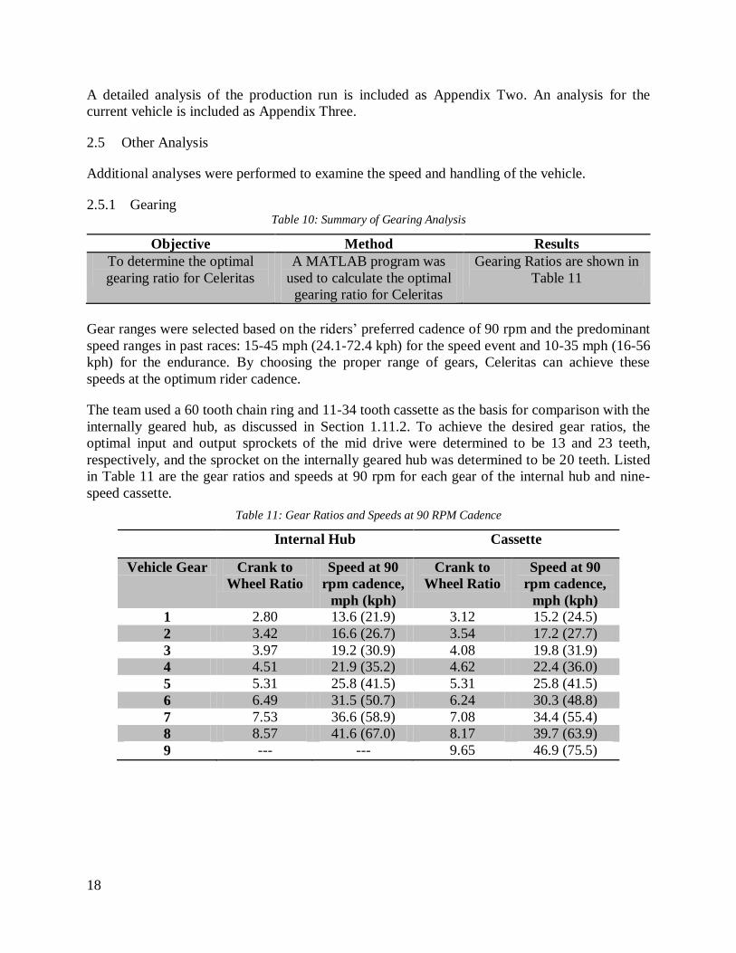
Gear ranges were selected based on the riders’ preferred cadence of 90 rpm and the predominant
speed ranges in past races: 15-45 mph (24.1-72.4 kph) for the speed event and 10-35 mph (16-56
kph) for the endurance. By choosing the proper range of gears, Celeritas can achieve these
speeds at the optimum rider cadence.
The team used a 60 tooth chain ring and 11-34 tooth cassette as the basis for comparison with the
internally geared hub, as discussed in Section 1.11.2. To achieve the desired gear ratios, the
optimal input and output sprockets of the mid drive were determined to be 13 and 23 teeth,
respectively, and the sprocket on the internally geared hub was determined to be 20 teeth. Listed
in Table 11 are the gear ratios and speeds at 90 rpm for each gear of the internal hub and nine-
speed cassette.
Table 11: Gear Ratios and Speeds at 90 RPM Cadence
Internal Hub Cassette
Vehicle Gear Crank to
Wheel Ratio
Speed at 90
rpm cadence,
mph (kph)
Crank to
Wheel Ratio
Speed at 90
rpm cadence,
mph (kph)
1 2.80 13.6 (21.9) 3.12 15.2 (24.5)
2 3.42 16.6 (26.7) 3.54 17.2 (27.7)
3 3.97 19.2 (30.9) 4.08 19.8 (31.9)
4 4.51 21.9 (35.2) 4.62 22.4 (36.0)
5 5.31 25.8 (41.5) 5.31 25.8 (41.5)
6 6.49 31.5 (50.7) 6.24 30.3 (48.8)
7 7.53 36.6 (58.9) 7.08 34.4 (55.4)
8 8.57 41.6 (67.0) 8.17 39.7 (63.9)
9 --- --- 9.65 46.9 (75.5)
Page 24
19
2.5.2 Stability Table 12: Summary of Stability Analysis
Objective Method Results
Design the vehicle geometry
in order to create a stable
design
A MATLAB program was
used to calculate lowest stable
speed
Celeritas is stable at speeds as
low as 9.5 ft/s (2.9 m/s)
The optimum rider position and seat angle for Celeritas were experimentally determined using a
variable geometry trainer. Given this information, the vehicle’s steering geometry was designed
using the results of a MATLAB script written by the team. This script uses information from the
Lords of the Chainring [9] to calculate the steering geometry of a two-wheeled vehicle. It was
used last year with great success on the 2012 Carηot Cycle. The script calculated the wheelbase
and was also used to determine the optimal head tube angle in order to reduce the low speed
steering input force, steering sensitivity, and the lowest stable speed of 9.5 ft/s (2.9 m/s).
2.5.3 Turning Radius Table 13: Summary of Turning Radius Analysis
Objective Method Results
To determine the turning
radius of Celeritas
Trigonometry was used to
determine the final turning
radius
Celeritas theoretically has a
turning radius of 13 ft (3.96 m)
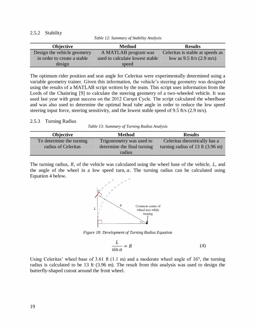
The turning radius, , of the vehicle was calculated using the wheel base of the vehicle, , and
the angle of the wheel in a low speed turn, . The turning radius can be calculated using
Equation 4 below.
Figure 18: Development of Turning Radius Equation
(4)
Using Celeritas’ wheel base of 3.61 ft (1.1 m) and a moderate wheel angle of 16°, the turning
radius is calculated to be 13 ft (3.96 m). The result from this analysis was used to design the
butterfly-shaped cutout around the front wheel.
Page 25
20
3 Testing
Rollover Protection System Testing 3.1
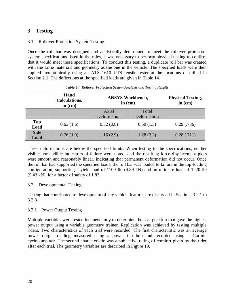
Once the roll bar was designed and analytically determined to meet the rollover protection
system specifications listed in the rules, it was necessary to perform physical testing to confirm
that it would meet these specifications. To conduct this testing, a duplicate roll bar was created
with the same materials and geometry as the one in the vehicle. The specified loads were then
applied monotonically using an ATS 1610 UTS tensile tester at the locations described in
Section 2.1. The deflections at the specified loads are given in Table 14.
Table 14: Rollover Protection System Analysis and Testing Results
Hand
Calculations,
in (cm)
ANSYS Workbench,
in (cm)
Physical Testing,
in (cm)
Axial
Deformation
Total
Deformation
Top
Load 0.63 (1.6) 0.32 (0.8) 0.50 (1.3) 0.29 (.736)
Side
Load 0.76 (1.9) 1.16 (2.9) 1.28 (3.3) 0.28 (.711)
These deformations are below the specified limits. When testing to the specifications, neither
visible nor audible indicators of failure were noted, and the resulting force-displacement plots
were smooth and reasonably linear, indicating that permanent deformation did not occur. Once
the roll bar had supported the specified loads, the roll bar was loaded to failure in the top-loading
configuration, supporting a yield load of 1100 lbf (4.89 kN) and an ultimate load of 1220 lbf
(5.43 kN), for a factor of safety of 1.83.
Developmental Testing 3.2
Testing that contributed to development of key vehicle features are discussed in Sections 3.2.1 to
3.2.8.
3.2.1 Power Output Testing
Multiple variables were tested independently to determine the seat position that gave the highest
power output using a variable geometry trainer. Replication was achieved by testing multiple
riders. Two characteristics of each trial were recorded. The first characteristic was an average
power output reading measured using a power tap hub and recorded using a Garmin
cyclocomputer. The second characteristic was a subjective rating of comfort given by the rider
after each trial. The geometry variables are described in Figure 19.
Page 26
21
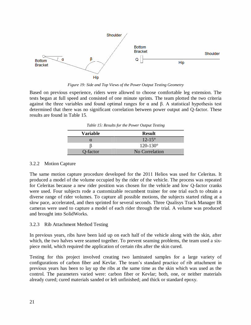
Figure 19: Side and Top Views of the Power Output Testing Geometry
Based on previous experience, riders were allowed to choose comfortable leg extension. The
tests began at full speed and consisted of one minute sprints. The team plotted the two criteria
against the three variables and found optimal ranges for α and β. A statistical hypothesis test
determined that there was no significant correlation between power output and Q-factor. These
results are found in Table 15.
Table 15: Results for the Power Output Testing
Variable Result
α 12-15°
β 120-130°
Q-factor No Correlation
3.2.2 Motion Capture
The same motion capture procedure developed for the 2011 Helios was used for Celeritas. It
produced a model of the volume occupied by the rider of the vehicle. The process was repeated
for Celeritas because a new rider position was chosen for the vehicle and low Q-factor cranks
were used. Four subjects rode a customizable recumbent trainer for one trial each to obtain a
diverse range of rider volumes. To capture all possible motions, the subjects started riding at a
slow pace, accelerated, and then sprinted for several seconds. Three Qualisys Track Manager IR
cameras were used to capture a model of each rider through the trial. A volume was produced
and brought into SolidWorks.
3.2.3 Rib Attachment Method Testing
In previous years, ribs have been laid up on each half of the vehicle along with the skin, after
which, the two halves were seamed together. To prevent seaming problems, the team used a six-
piece mold, which required the application of certain ribs after the skin cured.
Testing for this project involved creating two laminated samples for a large variety of
configurations of carbon fiber and Kevlar. The team’s standard practice of rib attachment in
previous years has been to lay up the ribs at the same time as the skin which was used as the
control. The parameters varied were: carbon fiber or Kevlar; both, one, or neither materials
already cured; cured materials sanded or left unfinished; and thick or standard epoxy.
Page 27
22
The samples were loaded to failure in a tensile tester. This simulated the shear force endured by
the ribs against the skin; the normal force was not tested because it is difficult to replicate.
The team examined the samples where carbon was laid up onto already cured carbon with
special interest because it best reflected laying up the ribs after the main fairing had cured. The
testing showed that this method was not as effective as epoxying together two layers of already-
cured carbon. The samples failed at averages of 2.10 ksi (14.5 MPa) and 2.65 ksi (18.3 MPa) of
shear stress, respectively. However, this method was very comparable to the control samples
where overlapping carbon pieces were laid up together, which failed at an average of 2.3 ksi
(15.9 MPa). This finding helped demonstrate that the team could lay up the ribs after the main
fairing cured without unreasonable losses in strength.
3.2.4 Protective Layer Testing
For the past six years, the team has used a layer of Kevlar fabric to protect the rider from debris
that could puncture the carbon fiber layer and injure the rider. The team has traditionally used a
medium-weight Kevlar 5285 to protect the rider, but alternative protective materials were
researched to replace it. Kevlar 5120 was tested against Kevlar 5285 because its lighter weight,
1.8 oz/yd2
(61 g/m2) compared to 5.25 oz/yd
2 (178 g/m
2), would reduce the total vehicle weight.
Kevlar 5120 also has a much tighter weave than Kevlar 5285 which increases the layer’s ability
to deflect carbon shards. Two samples each were tested against a control group of bare carbon
for protection from carbon shards and pavement abrasion.
The Kevlar samples were laminated onto carbon fiber measuring 6 x 8 in (152 x 203 mm). The
samples were tested using a 3-point load until the carbon fiber cracked. Table 16 shows the
results of a visual inspection for carbon shards that pierced the protective layer.
The candidate materials also needed to provide a final layer of protection against abrasion. For
the test, a curved layer of carbon fiber and protective material was created with a radius of 3 in
(7.6 cm) to simulate the curved surface of Celeritas. A 105 lbf (467 N) load was applied to each
sample, and the pieces were then dragged across pavement. Every 25 ft (7.6 m), the samples
were examined for any hole greater than 0.25 in (6.35 mm) in diameter. When such a hole was
found, the sample piece was considered destroyed and its final distance traveled was recorded.
Table 16: Carbon Fiber Penetration Test and Abrasion Test Results
Material Carbon Fiber Penetration
Test
Abrasion Test
Kevlar 5285 Pass 150ft
Kevlar 5120 Pass 200ft
Control-Bare Carbon Fiber Fail 75ft
Both Kevlar samples effectively stopped carbon fiber pieces from penetrating the protective
layer. In the abrasion test, however, the tighter-woven Kevlar 5120 lasted 30% longer than the
Kevlar 5285. Kevlar 5120 was chosen for use in the final vehicle instead of Kevlar 5285 because
of the lighter weight and increased abrasion resistance.
Page 28
23
3.2.5 Skid Testing
Extensive sliding during crashes poses a significant danger to the rider and causes wear to the
vehicle. The 2012 Carηot Cycle used automotive trim to lessen skidding. Automotive trim did
not fully protect the exterior from wear, was difficult to place, slightly degraded the
aerodynamics of the vehicle, and could not be replaced without aesthetic damage.
The team tested rubberized spray paint as a potential replacement to the automotive trim. The
2009 Mark IV had automotive trim applied on its right side and was coated with rubberized
spray on its left. A test course with a 200 ft (60.96m) run up and a 50 ft (15.24 m) skid zone was
laid out on pavement and the vehicle was crashed three times to each side. There was no
noticeable difference between the stopping distances of the two methods. The rubberized paint
was not as durable as the automotive trim and would have to be reapplied after 10 to 15 crashes.
The durability of the rubberized paint was also examined, as the paint would be required to last
through at least one competition before it could be reapplied. The single layer coating of paint
wore considerably after three crashes, failing to meet this requirement. Multiple coatings of the
rubber could be applied to improve durability, however more time is needed for this process as
compared to using automotive trim. The team chose to use automotive trim due to the rubberized
spray coating’s reduced durability.
To determine where the contact surface would be applied, the vehicle was rolled to each side into
a layer of talcum powder. The powder coated the vehicle at contact points and outlined where the
automotive trim needed to be applied.
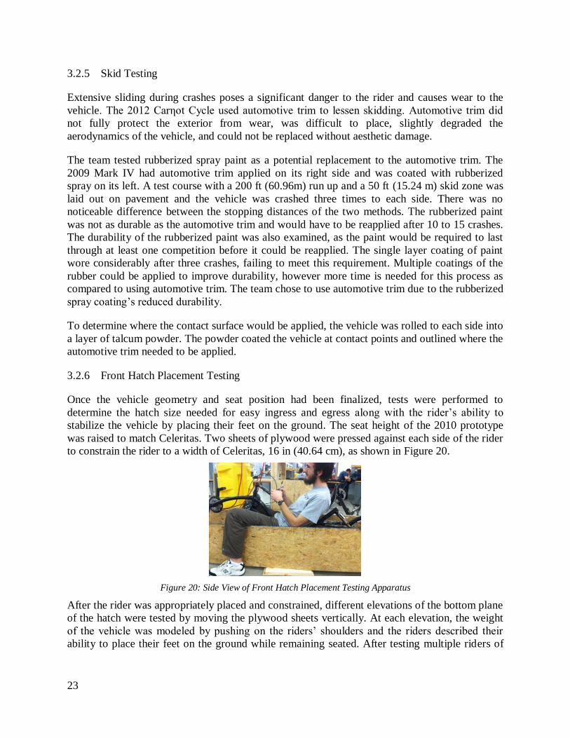
3.2.6 Front Hatch Placement Testing
Once the vehicle geometry and seat position had been finalized, tests were performed to
determine the hatch size needed for easy ingress and egress along with the rider’s ability to
stabilize the vehicle by placing their feet on the ground. The seat height of the 2010 prototype
was raised to match Celeritas. Two sheets of plywood were pressed against each side of the rider
to constrain the rider to a width of Celeritas, 16 in (40.64 cm), as shown in Figure 20.
Figure 20: Side View of Front Hatch Placement Testing Apparatus
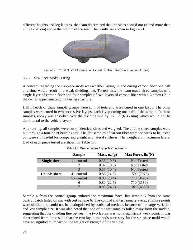
After the rider was appropriately placed and constrained, different elevations of the bottom plane
of the hatch were tested by moving the plywood sheets vertically. At each elevation, the weight
of the vehicle was modeled by pushing on the riders’ shoulders and the riders described their
ability to place their feet on the ground while remaining seated. After testing multiple riders of
Page 29
24
different heights and leg lengths, the team determined that the sides should not extend more than
7 in (17.78 cm) above the bottom of the seat. The results are shown in Figure 21.
Figure 21: Front Hatch Placement on Celeritas (Determined Elevation in Orange)
3.2.7 Six-Piece Mold Testing
A concern regarding the six-piece mold was whether laying up and curing carbon fiber one half
at a time would result in a weak dividing line. To test this, the team made three samples of a
single layer of carbon fiber and four samples of two layers of carbon fiber with a Nomex rib in
the center approximating the fairing structure.
Half of each of these sample groups were control tests and were cured in one layup. The other
samples were cured in two successive layups, each layup curing one half of the sample. In these
samples, epoxy was absorbed over the dividing line by 0.25 in (6.35 mm) which would not be
detrimental to the vehicle layup.
After curing, all samples were cut to identical sizes and weighed. The double sheet samples were
put through a four-point bending test. The flat samples of carbon fiber were too weak to be tested
but were still useful for comparing weight and lateral stiffness. The weight and maximum lateral
load of each piece tested are shown in Table 17.
Table 17: Discontinuous Layup Testing Results
Sample Mass, oz (g) Max Force, lbf (N)
Single sheet 1 - control 0.36 (10.3) Not Tested
2 0.37 (10.5) Not Tested
3 0.37 (10.4) Not Tested
Double sheet 4 - control 0.86 (24.3) 1590 (7076)
5 - control 0.83 (23.4) 770 (3426)
6 0.80 (22.7) 710 (3159)
7 0.85 (24.2) 1020 (4539)
Sample 4 from the control group endured the maximum force, but sample 5 from the same
control batch failed on par with test sample 6. The control and test sample average failure points
were similar and could not be distinguished by statistical methods because of the large variation
and low sample size. It was also noted that one of the test samples failed away from the middle,
suggesting that the dividing line between the two layups was not a significant weak point. It was
determined from the results that the two layup methods necessary for the six-piece mold would
have no significant impact on the weight or strength of the vehicle.
Page 30
25
3.2.8 Gelcoat
The team investigated alternate methods of mold surfacing because the fiberglass layer that was
used in previous years was difficult to apply and required large amounts of sanding. The team
chose to test a modified gelcoat that was easy to apply as an alternative mold surface. The
gelcoat used was a mixture of thick epoxy (cured with 1:1 by volume hardener) and varying
amounts of talc powder. The ratio between epoxy and thick hardener in the epoxy solution was
kept constant to allow the gelcoat to fully cure while the talc to epoxy solution volumetric ratio
was varied between 0.5:1 and 1:1. The gelcoats were applied to 6 x 6 in (15.24 x 15.24 cm)
square samples of foam, placed vertically to simulate the sloped surfaces of the mold, allowed to
dry, and sanded till smooth.
The trend that emerged in the test results was that as the ratio of talc to epoxy solution was
increased from 0.5:1 to 1:1, the samples became thicker and contained fewer bubbles. From the
testing, the team decided to use the gelcoat with equal volumes epoxy solution and talc for
surfacing the mold.
Performance Testing 3.3
Testing that contributed to the performance of the vehicle is discussed in Section 3.3.1.
3.3.1 Visibility
The rider’s visibility from within the vehicle is a crucial component of safety. To test the scope
of rider visibility, team members sat in the vehicle and reported the limits of their visibility in
each direction. The total visibility was calculated as the average of these reported limits. The
results of the testing are displayed graphically in Figure 22. The crosshatching represents the
area of the ground that is not visible to the rider.
Figure 22: Field of Vision for Celeritas Represented by the Non-Crosshatched Area
Page 31
26
The rider has a minimum of 200 degrees of forward visibility and can see the ground 23 ft (7.0
m) in front of the vehicle. Objects any taller than a few inches are visible at much closer ranges
to the vehicle, and objects taller than 2 ft (0.61 m) are visible immediately next to the vehicle.
Side mirrors mounted on the fairing add 100 degrees of vision to the rear of the vehicle.
4 Safety
Safety is a crucial component of the team as seen in the HoQ where minimizing rider injury is
shown as the first and foremost vehicle need, Section 1.5.
Design for Safety 4.1
In the design of Celeritas, safety of the rider and manufacturers was of the utmost concern.
Therefore, all components, vehicle systems, and manufacturing methods were evaluated for their
safety mechanics prior to implementation.
4.1.1 Roll Bar
A composite roll bar is included in Celeritas to ensure the safety of the rider in a rollover or side
impact collision. The roll bar prevents contact between the rider and the road surface and lessens
the impact in the event of a crash. The design of the roll bar improves upon that of previous years
as described in Section 2.1 and exceeds the competition requirements.
4.1.2 Windshield
The vehicle’s windshield is made of polycarbonate, which provides high impact resistance.
Because of this, the windshield is very secure and can protect the rider both while riding and
during a crash. It gives a total of 300 degrees of visibility, as mentioned in Section 3.3.1,
exceeding the competition requirements.
4.1.3 Seatbelt
The seatbelt on Celeritas is a three-point harness as used on the 2012 Carηot Cycle. It was
chosen over a four-point harness to allow for faster ingress and egress times. It is secured in the
same fashion as the 2012 Carηot Cycle, with the top point riveted to a steel plate that is attached
to the roll bar. The lower two points are attached to plates embedded in the fairing. Based on
previous testing, the belt will hold a total of 1650 lbf (7335 N) before failing [2], meeting the
requirements set forth in the rules. This ensures that the rider will be safe in the event of a crash.
4.1.4 Safety of Manufacturing
In order to ensure the safety of manufacturability of Celeritas, a three-tier system was employed.
The first tier was to educate members on the safe use of power tools. Members were not
permitted to work alone when using power tools. The second tier required members to use proper
personal protective equipment (PPE) when partaking in team activities. Examples of PPE include
the use of respirators when sanding carbon and wearing safety glasses at all times. The third tier
consisted of a number of decisions to increase safety during construction. An important decision
of construction was to use epoxy resin instead of polyester resin, which is cheaper but toxic. In
Page 32
27
order to promote further safety, sharp edges on the flanges of the fairing were trimmed off to
prevent injury when handling the components.
Hazard Analysis 4.2
Safety of the rider is held paramount when considering any of the components that make up the
vehicle. The design also specifically addresses some of the known hazards. To comply with the
standard rules of the competition, all riders are required to wear a helmet when in the vehicle. As
shown in Section 3.1, the fairing can withstand side impact and rollover situations. In addition to
the roll bar, the rider is protected by a roll hoop surrounding their feet. To help protect the
shoulders and arms during a crash with the top fairing removed, flanges extend forward from the
roll bar.
Kevlar 5120 fabric is used to line the cockpit where the rider sits. In the event that the carbon
fiber splinters, the Kevlar acts as a safety net. Sharp edges that have developed during the
manufacturing process are either removed or covered by rounded edging.
Uncontrolled skidding after a fall can be more dangerous than the fall itself. To reduce the
skidding, rubber automotive trim was placed at contact points on the fairing. The automotive
trim also protects the fairing’s structural integrity against abrasion.
To help the rider communicate their intentions and make their presence known to other vehicles
and pedestrians, standard equipment such as headlights, taillights, brake lights, turn signals, side
reflectors, and a loud electronic horn have been installed. The vehicle’s low height makes it less
visible on the road. To correct this, there is a mounting hole on the back of the vehicle to hold an
optional safety flag for increased visibility.
5 Aesthetics
An important factor in a customer’s decision to purchase a product is the appearance. For this
reason, the team consciously designed to improve the aesthetic appeal of the vehicle both as a
newly finished product and throughout its life.
To ensure that the vehicle is attractive, several methods are employed. First, the snap fits,
described in Section 1.3, ensure that removable fairing components fit snugly without
unattractive gaps. Attention is also given to the paint scheme which serves to mask the
unattractive imperfections in the fairing. The interior is also painted to allow the vehicle to
appear attractive regardless of fairing configuration. Care is given to internal components to
appear clean and professional, and waterproof paint is used to allow for easy cleaning of the
vehicle.
When considering the long-term appearance of the vehicle, the team realized that the vehicle will
inevitably crash and accumulate scratches and scrapes. The automotive trim used to minimize
skidding, as described in Section 4.1, has the added benefit of minimizing contact between the
ground and many painted areas of the vehicle. The team has switched to using chopped fiber,
which is made by cutting up scrap pieces of carbon fiber and separating individual fibers, then
mixing with epoxy to give a fuzzy filler material to fill surface imperfections rather than Bondo.
Page 33
28
Chopped fiber appears very similar to laid up carbon fiber, and will degrade more gracefully than
Bondo.
6 Conclusion
Comparison 6.1
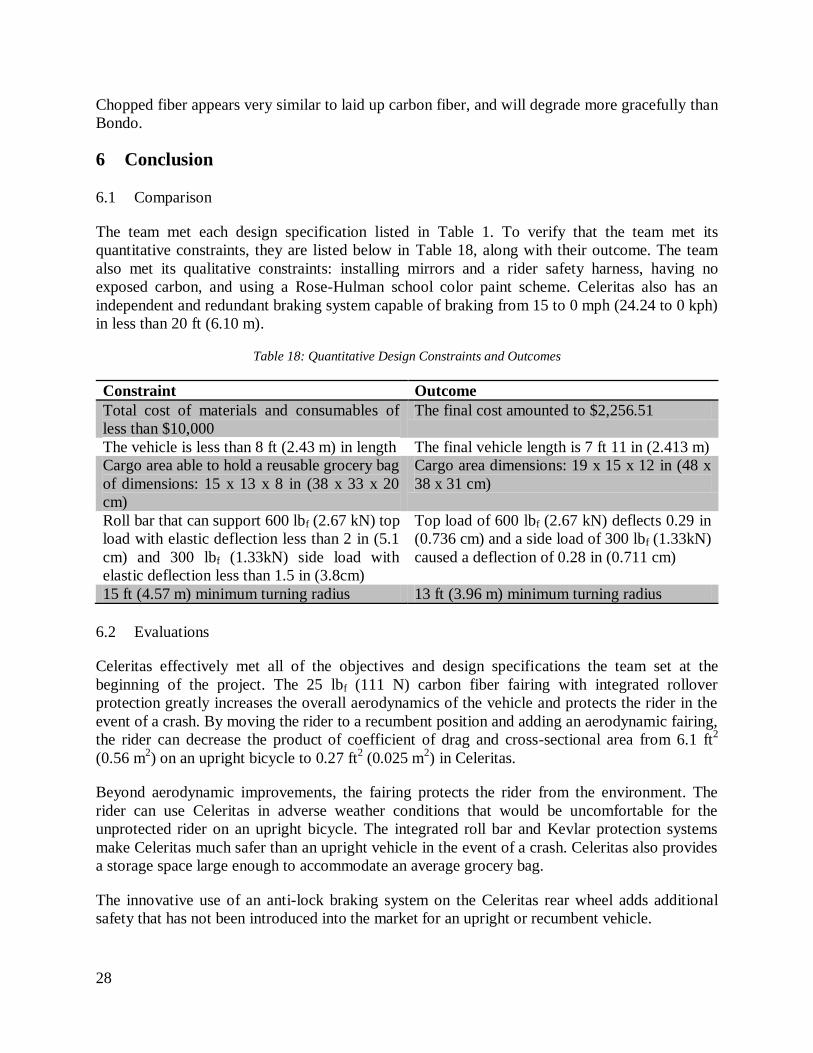
The team met each design specification listed in Table 1. To verify that the team met its
quantitative constraints, they are listed below in Table 18, along with their outcome. The team
also met its qualitative constraints: installing mirrors and a rider safety harness, having no
exposed carbon, and using a Rose-Hulman school color paint scheme. Celeritas also has an
independent and redundant braking system capable of braking from 15 to 0 mph (24.24 to 0 kph)
in less than 20 ft (6.10 m).
Table 18: Quantitative Design Constraints and Outcomes
Constraint Outcome
Total cost of materials and consumables of
less than $10,000
The final cost amounted to $2,256.51
The vehicle is less than 8 ft (2.43 m) in length The final vehicle length is 7 ft 11 in (2.413 m)
Cargo area able to hold a reusable grocery bag
of dimensions: 15 x 13 x 8 in (38 x 33 x 20
cm)
Cargo area dimensions: 19 x 15 x 12 in (48 x
38 x 31 cm)
Roll bar that can support 600 lbf (2.67 kN) top
load with elastic deflection less than 2 in (5.1
cm) and 300 lbf (1.33kN) side load with
elastic deflection less than 1.5 in (3.8cm)
Top load of 600 lbf (2.67 kN) deflects 0.29 in
(0.736 cm) and a side load of 300 lbf (1.33kN)
caused a deflection of 0.28 in (0.711 cm)
15 ft (4.57 m) minimum turning radius 13 ft (3.96 m) minimum turning radius
Evaluations 6.2
Celeritas effectively met all of the objectives and design specifications the team set at the
beginning of the project. The 25 lbf (111 N) carbon fiber fairing with integrated rollover
protection greatly increases the overall aerodynamics of the vehicle and protects the rider in the
event of a crash. By moving the rider to a recumbent position and adding an aerodynamic fairing,
the rider can decrease the product of coefficient of drag and cross-sectional area from 6.1 ft2
(0.56 m2) on an upright bicycle to 0.27 ft
2 (0.025 m
2) in Celeritas.
Beyond aerodynamic improvements, the fairing protects the rider from the environment. The
rider can use Celeritas in adverse weather conditions that would be uncomfortable for the
unprotected rider on an upright bicycle. The integrated roll bar and Kevlar protection systems
make Celeritas much safer than an upright vehicle in the event of a crash. Celeritas also provides
a storage space large enough to accommodate an average grocery bag.
The innovative use of an anti-lock braking system on the Celeritas rear wheel adds additional
safety that has not been introduced into the market for an upright or recumbent vehicle.
Page 34
29
Recommendations 6.3
Though Celeritas is a capable vehicle that met the team’s goals and constraints, there are a few
additional features that should be incorporated into the vehicle and processes that should be
changed for future vehicle designs. Adding an electric motor and battery pack to Celeritas would
greatly increase the marketability and the number of interested parties. An electric motor would
allow the rider to maintain pace with higher speed traffic and would help the vehicle up hills.
Further iterations of the electric assist system could increase efficiency and versatility by
incorporating a regenerative breaking system or another system that allow the rider to recharge
the batteries on long trips.
To increase the production scale from a one-off prototype to 10 vehicles per month, the
manufacturing process must be adjusted and fine-tuned. This year’s mold was not strong enough
to be used for more than one vehicle. To increase the durability of the mold, the surface should
be reinforced with fiberglass before the application of the gelcoat. The top hatches should be
redesigned to allow for access to the rear interior of the fairing during the final layup of the
vehicle. The team should also use a vacuum bag that encompasses the entire mold, box, and all
excess material hanging over the side of the mold in order to capture any leaks between the
sections of the mold.
Conclusion 6.4
The Rose-Hulman Human Powered Vehicle Team set out to create a lightweight, efficient, and
agile vehicle that could safely and effectively be used for everyday transportation. The use of
advanced composite materials in Celeritas provides an exceptional strength-to-weight ratio that
minimizes the material necessary for a full structural fairing. Celeritas is highly efficient when
compared to upright bicycles, requiring 22 times less power to overcome air drag at the same
speed. Its small frontal profile and streamlined body allow it to travel upwards of 45 mph (73.6
kph), yet it retains low-speed maneuverability with self-stabilization and features like landing
gear. Finally, Celeritas protects the rider with an integrated rollover protection system, harness,
and Kevlar lining. Its combined efficiency, safety, and utility make it well-suited to capture a
market segment in sustainable transportation.
Page 35
30
7 Appendices
Appendix One 7.1
Objective
The team developed an anti-lock braking system (ABS) for Celeritas to reduce the number of
crashes caused by locking the rear wheel during braking and to increase rider safety. Locking the
wheel occurs when the rider applies too much force to the brake which stops the rotation of the
wheel. This is common in recumbent vehicles due to the large number of new riders and the
different weight distributions between recumbent vehicles and conventional upright bicycles.
Less weight on the rear wheel makes it easier to lock up, which causes loss of control of the
vehicle. Although ABS is primarily intended for casual riders, even experienced riders will
benefit from this system in an emergency when fast, controlled stopping is necessary.
Description
When using a normal disk brake on any bicycle, riders must modulate the brakes to apply a high
braking force without locking the rear wheel. This maintains static friction between the wheel
and the ground, maximizing braking force and providing control to the rider. Keeping the rear
wheel in motion during harsh braking requires skill and concentration, which is difficult to
maintain while avoiding a hazard. The ABS developed for Celeritas automates brake modulation.
Due to the weight distribution of the vehicle, the rear wheel will lock before the front wheel.
Because the rear wheel will lock first, ABS is only mounted there. Using a cable-actuated brake
on the front wheel provides redundancy to mitigate the risks of an ABS failure, such as power
loss. This combination of braking systems provides greater safety than either system alone.
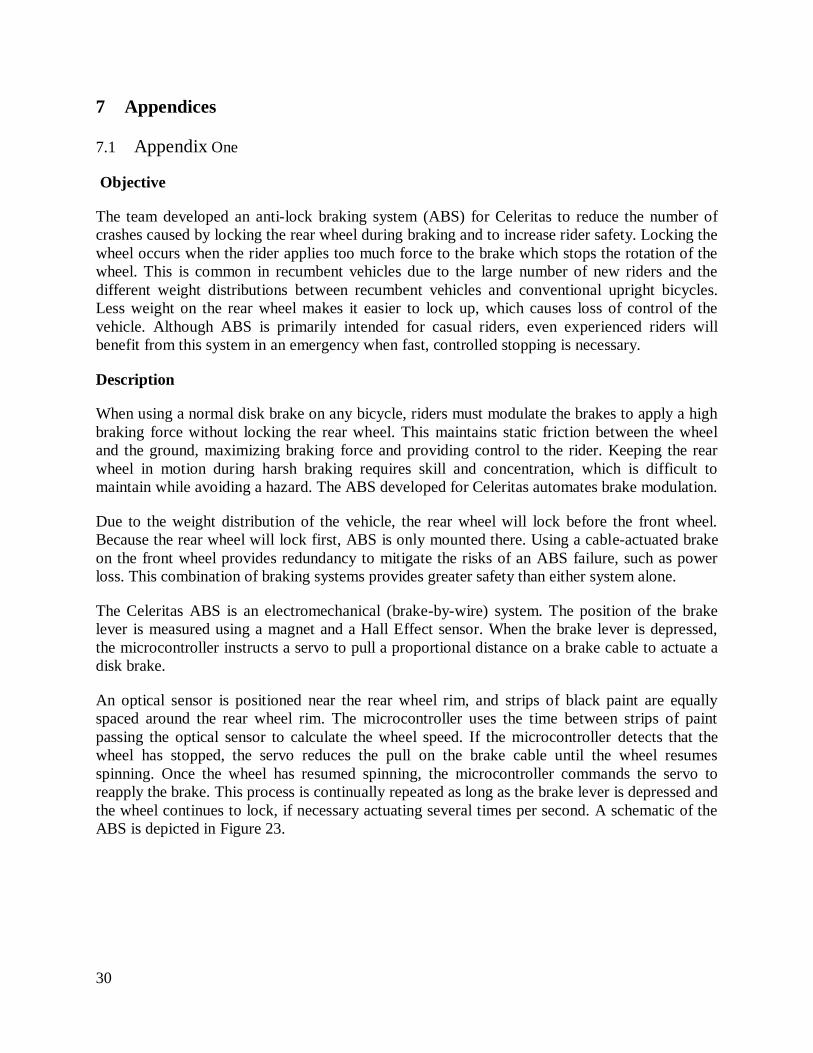
The Celeritas ABS is an electromechanical (brake-by-wire) system. The position of the brake
lever is measured using a magnet and a Hall Effect sensor. When the brake lever is depressed,
the microcontroller instructs a servo to pull a proportional distance on a brake cable to actuate a
disk brake.
An optical sensor is positioned near the rear wheel rim, and strips of black paint are equally
spaced around the rear wheel rim. The microcontroller uses the time between strips of paint
passing the optical sensor to calculate the wheel speed. If the microcontroller detects that the
wheel has stopped, the servo reduces the pull on the brake cable until the wheel resumes
spinning. Once the wheel has resumed spinning, the microcontroller commands the servo to
reapply the brake. This process is continually repeated as long as the brake lever is depressed and
the wheel continues to lock, if necessary actuating several times per second. A schematic of the
ABS is depicted in Figure 23.
Page 36
31
Figure 23: ABS Components for Celeritas
Literature Review
From research, the team discovered that anti-lock braking has a long history. According to the
Insurance Institute for Highway Safety, the first use of ABS occurred in airplanes in the 1950s
[10]. The use of ABS expanded to automobiles in 1969 with the Ford Thunderbird [10]. ABS for
two-wheeled vehicles was introduced in 1988 when BMW debuted the K 100 model motorcycle
[11]. Due to ABS’s growth in reliability and importance, the U.S. government now requires anti-
lock brakes on all passenger vehicles as of the 2012 model year [10].
Many patents mark the advancement of ABS. Filed in 1971, U.S. Patent 3753598 was one of the
earliest US ABS patents, describing a “hydraulic antiskid vehicle braking system” [12]. US
Patent 5634533 expanded the market in 1994 by patenting an ABS specifically for bicycles and
motorcycles [13]. Finally, U.S. Patent 0111342 discussed an electronic ABS system in 2006. It
used a wheel speed sensor to judge when to apply braking force from an electric motor through a
hydraulic actuator.
ABS is not a novel idea for transportation. However, the basic groundwork of ABS for bicycles
is still being laid. According to the team’s research, there has been little to no development of
ABS specifically for recumbent vehicles. While electronic ABS for bicycles has been patented
and is advancing among hobbyists, there are no commercially available products. Furthermore,
according to the team’s research, all current electronic anti-lock brake systems make use of a
hydraulic actuator to apply braking force as opposed to an electronic servo.
The team’s ABS is groundbreaking because it is specifically designed for recumbent vehicles. It
also is novel because it is an entirely electronic system, utilizing a servo instead of a hydraulic
actuator. Even though multiple aspects of the system are covered by existing patents, the team’s
ABS does introduce an innovative feature set and implementation that is not found in existing
literature. Therefore, the system could be patented.
Testing
The Celeritas ABS was developed using a previous year’s prototype vehicle. This vehicle had
similar geometry to Celeritas with slightly less weight. With ABS disabled, the brake-by-wire
system was able to lock the rear wheel, demonstrating that the motor can apply adequate braking
force. Testing showed that the vehicle is capable of stopping within the ASME specification
Page 37
32
relying on the ABS alone. Furthermore, the ABS prevents the rear wheel from locking when
harshly applying the rear brake at a speed of 30 mph (48.6 kph), where this would commonly
lock up the rear wheel without it.
Further refinements are being made on the control algorithm, and further testing is planned. Both
will be described in the design report update.
Market Analysis Table 19: Market Analysis for the ABS
Item Cost
Servo (Futuba S3306) $40
Microcontroller (ATMega 328P) $4
Power Electronics $5
Circuit Board $10
Optical Sensor $2
Brake Lever Sensor $5
Total $68
The total cost of the ABS was under $70. It could be marketed as a $150 add-on feature to
Celeritas to improve safety and braking performance, especially for inexperienced riders.
Though there are no commercial electronic ABS for upright or recumbent bicycles, there are a
few mechanical ABS add-ons for upright bicycles on the market today. King Industries sells a
$100 product that produces a strictly mechanical braking frequency by the motion of the wheel,
[14] and Budbrake sells a $55 aftermarket brake system that works by applying braking force
equally to the front and rear wheels [15]. Winck, Marek, and Ngoo published a paper in the SAE
World Congress 2010 showing that a rudimentary pneumatic ABS could greatly benefit
emergency braking for bicycles [16].
Recommendations
The ABS has definite improvements which could be made to better the system’s benefit to the
vehicle. The electrical components could be encased to protect them from water and other debris.
By using higher quality components and more efficient design, the overall system sensitivity to
rider input could also be increased.
A smaller package and a universal mounting system would allow the ABS to be more functional.
This would make the system lighter and easier mount as well as give the team the ability to sell
the ABS as a separate component for any bicycle.
The robustness of the system could be improved by utilizing a mechanical backup brake that
would override the ABS in the case of a failure. Such a failure could be the effect of power loss
or damage to the system. The mechanical backup would improve the safety of the vehicle by
allowing the rider to have an auxiliary system.
Page 38
33
Appendix Two 7.2
Per Celeritas 3 year run
Capital Investment
Machine Subtotal $130.56 $47,000.00
Tools Subtotal $3.86 $1,390.00
Total $134.42 $48,390.00
Tooling
Layups Subtotal $316.47 $113,928.00
General Subtotal $28.35 $10,206.48
Total $344.82 $124,134.48
Parts and Materials
Bike Parts Subtotal $655.04 $235,814.40
Composites Subtotal $898.13 $323,326.80
Sub Frame Subtotal $201.01 $72,363.60
Electrical Subtotal $128.23 $46,162.80
ABS Subtotal $100.00 $36,000.00
Telemetry Subtotal $102.00 $36,720.00
Landing Gear Subtotal $252.29 $90,824.40
Mold Subtotal $423.13 $152,325.60
Other Subtotal $50.00 $18,000.00
Total $1,911.70 $688,210.80
Labor
Man hours 90.80 32,688.00
Labor Cost $25.00 $/hr
Total $2,270.00 $817,200.00
Overhead
Staff Subtotal $833.33 $300,000.00
Salary Subtotal $465.50 $167,580.00
Facilities Subtotal $154.17 $55,500.00
Utilities Subtotal $25.00 $9,000.00
Furniture Rental Subtotal $2.78 $1,000.00
Insurance Subtotal $69.44 $25,000.00
Total $1,550.22 $558,080.00
Total Costs: $6,211.15 $2,236,015.28
Page 39
34
Appendix Three 7.3
Category Item Purchased Amount
Tooling
Layups Gloves, popsicle sticks, screws $20.18
Gloves $10.69
Cups, measuring cups, spoons $7.93
Peel ply $147.50
Breather cloth $130.00
Blender $0.17
Layups Subtotal: $316.47
General Dremel Kit $1.11
Replacement Bit for CNC $4.98
Sandpaper, Bondo hardener $19.06
Sandpaper $3.21
General Tooling Subtotal: $28.35
Tooling Subtotal: $344.82
Parts and Materials
Bike Parts Tires 2 bikes worth $132.45
Shimano Nexus/Alfine 8 speed Shifter $88.00
Shifter barrel cable adjusters $9.99
Microshift derailleur $74.00
9 speed bike chain x4 $27.10
Tektro calipers $55.55
Ultegra derailleur $84.98
Chain ring bolts $29.97
Cranks $60.00
Head tube $37.00
Bottom bracket $26.00
Fork $30.00
Bike Parts Subtotal: $655.04
Composites Carbon Fiber (20 yards) $365.90
Kevlar $140.00
Unidirectional $119.00
Epoxy $200.00
Polycarbonate $7.00
1/4 in Nomex $36.13
3/4 in Nomex $30.10
Composites Subtotal: $898.13
Subframe Steel tubing $29.68
Steel bearings $42.95
Rectangular tubing $128.38
Page 40
35
Subframe Subtotal: $201.01
Electrical Rechargeable Battery $48.23
Wires $5.00
White LED's $20.00
Red LED's $15.00
Bike computer $40.00
Electrical Subtotal: $128.23
ABS Servo $50.00
Potentiometer $10.00
Optical Encoder $20.00
Microcontroller $20.00
ABS Subtotal: $100.00
Telemetry 2.4 GHz Radios $40.00
FTDI Serial to USB $10.00
GPS $40.00
Misc. Electronics $12.00
Telemetry Subtotal: $102.00
Landing Gear
600:1 Gear motor $24.49
Teflon bar 3/8” x 3/8” x 5’ $79.92
Steel tubing $59.40
Misc. components $9.42
PK27 Geared Motor 27:1 $47.99
Misc. Electronics $31.07
Landing Gear Subtotal: $252.29
Other Seat Belt $44.00
Thermoform Plastic $6.00
Other Subtotal: $50.00
Molds Foam $165.85
Thick Epoxy, Resin (2 molds) $123.41
Caster wheels $13.86
Wood $120.00
Mold Tooling Subtotal: $423.13
Parts and Materials Subtotal: $1,911.70
Total: $2,256.51
Page 41
36
Works Cited
[1] Bikes Belong, 2013, "Participation Statistics," Bikes Belong, from www.bikesbelong.org
[2] Rose-Hulman Human Powered Vehicle Team, 2009, "2009 Human Powered Vehicle Team
Design Report- West," Terre Haute.
[3] Rose-Hulman Human Powered Vehicle Team, 2010, "2010 Human Powered Vehicle Team
Design Report- West,".
[4] Rose-Hulman Human Powered Vehicle Team, 2011, "2011 Human Powered Vehicle Team
Design Report- West,".
[5] Rose-Hulman Human Powered Vehicle Team, 2012, "2012 Human Powered Vehicle Team
Design Report- West,".
[6] Disley, B.X., 2012, "The effect of Q Factor on gross emchanical efficiency ad muscular
activation in cycling ," Scandinavian Journal of Medicing & Science in Sports.
[7] The Weather Channel, 2013, "Average Weather for Big Rapids, MI. and Mountain View,
CA.," from www.weather.com
[8] American Society of Mechanical Engineers, 2012, "2013 Human Powered Vehicle
Challenge,".
[9] Patterson, W., 1998, The Chronicles of the Lords of the Chainring, 5th ed., W.B. Patterson,
Santa Maria, CA, p. 109.
[10] Insurance Institute for Highway Safety, 2013, "Q&A: Antilock Brakes," from
http://www.iihs.org/research/qanda/antilock.aspx
[11] Bayerische Motoren Werke AG, 1988, "1988 ABS Press Release," from
http://www.bmbikes.co.uk/photos/press%20PDF/1988%20ABS%20Press.pdf
[12] Michellone, G., "Hydraulic Antiskid Vehicle Braking System, Having Two Modes of
Operation," U.S. Patent Office,.
[13] Zago, M., 1994, "Braking device particularly for bicycles and motorcycles," U.S. Patent
Office,.
[14] King Industries, Inc, 2011, "Safe Anti-Locking Braking System," from
http://www.kingindustries.ca/SABS.htm
[15] Budbrake, 2012, "Budbrake ABS Modulator," from http://budbrake.com
[16] Wink, R., Marek, K., and Ngoo, C., 2010, "Active Anti-lock Brake System for Low
Powered Vehicles Using Cable-Type Brakes," 2010-01-0076, SAE International.
[17] Van Niekerk, J., and Schlesinger, P., 2006, "Bicycle having an antilock brake," U.S. Patent
Office,.