Vehicle Load Optimization in Structural Bridge Design David Geeves – Autodesk SE6327 This class examines the difference between the traditional methods used to create traffic load combinations on bridge structures and the load optimization methods used in Structural Bridge Design software. We will examine the techniques that the program uses to create the most adverse loading patterns according to the specification of a variety of bridge design codes. A number of different user-defined parameters are used to control the behaviour of the module and we will examine these in detail. We will also discuss the benefits and timesaving gained from using the resulting workflow. Additionally, we will use a demonstration to show how the optimization method fits into the general workflow of the design process. Learning Objectives At the end of this class, you will be able to: Understand the basic techniques behind the method of load optimisation Understand a variety of load models for different design standards Correctly set the optimisation parameters for efficiency and accuracy and examine the results efficiently to check combination created and factors used. Use load optimisation to improve the workflow for bridge girder design. About the Speaker David is a technical specialist for Autodesk providing support and training for civil and structural software. He is a chartered civil engineer, graduating from the University of Sheffield UK in 1974, and spent the first part of his career on site and then in the design office working on a number of major projects culminating in the seismic design of nuclear power stations. He then moved into software development for civil and structural engineers, where he focused on the analysis and design of bridge structures, and became heavily involved in the development of the load optimisation techniques which are now used in Autodesk Structural Bridge Design. [email protected]
Transcript
Vehicle Load Optimization in Structural Bridge Design
David Geeves – Autodesk
SE6327
This class examines the difference between the traditional methods used to create traffic load combinations on bridge structures and the load optimization methods used in Structural Bridge Design software. We will examine the techniques that the program uses to create the most adverse loading patterns according to the specification of a variety of bridge design codes. A number of different user-defined parameters are used to control the behaviour of the module and we will examine these in detail. We will also discuss the benefits and timesaving gained from using the resulting workflow. Additionally, we will use a demonstration to show how the optimization method fits into the general workflow of the design process.
Learning Objectives At the end of this class, you will be able to:
Understand the basic techniques behind the method of load optimisation
Understand a variety of load models for different design standards
Correctly set the optimisation parameters for efficiency and accuracy and examine the results
efficiently to check combination created and factors used.
Use load optimisation to improve the workflow for bridge girder design.
About the Speaker
David is a technical specialist for Autodesk providing support and training for civil and structural software.
He is a chartered civil engineer, graduating from the University of Sheffield UK in 1974, and spent the first
part of his career on site and then in the design office working on a number of major projects culminating
in the seismic design of nuclear power stations. He then moved into software development for civil and
structural engineers, where he focused on the analysis and design of bridge structures, and became
heavily involved in the development of the load optimisation techniques which are now used in Autodesk
Traffic Load Optimisation in Autodesk® Structural Bridge Design..........................................27
General Procedure .............................................................................................................27
Parameters for BS5400 Bridges .........................................................................................32
Parameters for Eurocode Bridges (with UK National Annex) ..............................................33
Parameters for AS5100 Bridges .........................................................................................34
How Optimisation process fits into general bridge analysis workflow .....................................35
General Procedure .............................................................................................................35
Vehicle Load Optimization in Structural Bridge Design
3
Introduction Most of us drive along motorways, freeways, autobahns, without noticing the hundreds of structures we are driving over. Every culvert, canal bridge, river, railway and other highways have to be traversed, but it is the skill of the civil engineer that makes this experience one that we don’t even notice. The skill we have is to make these structures blend into the environment yet withstand the environmental loads and man-made loads applied to them. As civil engineers we need to ensure that whatever bridges we design they will be robust and will still be standing and capable of resisting the loads they were designed for over the design life and beyond. Why is it so important to discuss traffic loadings on a bridge? Well one reason is that traffic loading is nor easy to define and that it is quite difficult to predict in terms of the changes that will occur over time. One thing that differentiate bridges from many other forms of structures is the great variation in the type and value of different loadings and the almost infinite variation of combinations of these loads that need to be considered. Over the years many studies have been carried out, around the world, to try to quantify the types of traffic and the growth in volume and weight. This has eventually resulted in the development of a variety of equivalent models that reflect the recorded load distributions and trends. It is these models that are used in current codes of practice to represent characteristic or nominal loads that we use for bridge design. In years gone by, bridges were designed with a huge amount of safety and redundancy because of this uncertainty in the analysis methods and the prediction of traffic loads over time. Many older bridges were designed with very little accuracy so a huge factor of safety was put on any simple calculations that were carried out. Today we are expected to design with accuracy and efficiency, because we have the tools to do so, and quite rightly so. In doing so, we have to understand the basic principles behind the structures we design and where the loads that we apply to our structural models are derived from. When I started in the design office, many many years ago, when the most sophisticated computer was a programmable calculator, the concept of influence lines was reasonably well understood and used to determine the optimum position of traffic loads on a line beam analysis. This was reasonably simple but quite time consuming as the calculations were done by hand, and the accuracy of a line beam analysis on many structures was not very good. The introduction of computers and their applications into the design office was a huge revolution in the way we analysed structures. We no longer had to use moment redistribution to analyse a simple structure for a handful of load cases but we could use more accurate finite elements with hundreds of load cases, in a fraction of the time. As computers got faster, and could handle more and more data, the finite elements meshes got finer and finer and the hundreds of load cases became thousands. This led to a new problem in that although the computer says “42”, engineers had to have a way of validating the answer and this was difficult because everything was in a “black box”. Fortunately today we have taken a step back and developed computer methods that produce answers that are easier to validate by either “drilling down” into the calculations or having a more visual representation. Going back to using influence lines and optimising the critical
Vehicle Load Optimization in Structural Bridge Design
4
position of traffic loading using computer technology has greatly improved the efficiency and workflow that we noe see in most brideg design offices The validity of old methods is not put into question but it is important to make sure we are fully aware of all the tools that are at our disposal to ensure that we provide the most robust and efficient design that we can possibly achieve in the current times. This presentation has been developed to provide a background on the basics of how we design for traffic loading taking into consideration the variety of standard and codes of practice that have been developed on this subject around the world.
Vehicle Load Optimization in Structural Bridge Design
5
Influence Lines and Surfaces
Basic Theory
Definitions
An influence diagram for a particular point describes the “effect” at that point due to a
unit point load being applied anywhere on the structure.
In an influence “line”, the horizontal ordinate describes the position of the unit point load
along a line and the vertical ordinate represents the influence of the unit point load at
the design point
A load applied anywhere on the beam where the influence value is positive has an
adverse effect, elsewhere it is relieving.
An influence “surface” is a 2D representation of several influence lines where both
longitudinal and transverse load distributions are accounted for.
Vehicle Load Optimization in Structural Bridge Design
6
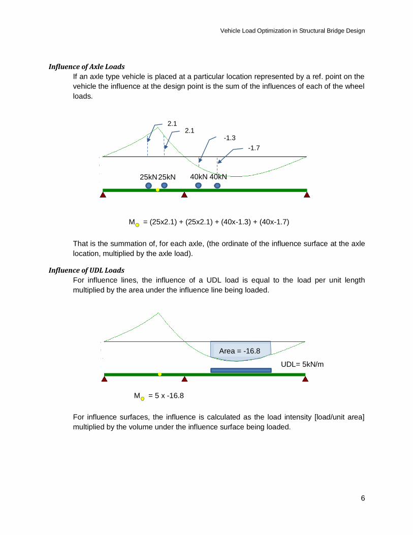
Influence of Axle Loads
If an axle type vehicle is placed at a particular location represented by a ref. point on the
vehicle the influence at the design point is the sum of the influences of each of the wheel
loads.
That is the summation of, for each axle, (the ordinate of the influence surface at the axle
location, multiplied by the axle load).
Influence of UDL Loads
For influence lines, the influence of a UDL load is equal to the load per unit length
multiplied by the area under the influence line being loaded.
For influence surfaces, the influence is calculated as the load intensity [load/unit area]
multiplied by the volume under the influence surface being loaded.
UDL= 5kN/m
Area = -16.8
2.1 2.1
-1.3
-1.7
25kN 25kN 40kN 40kN
M = (25x2.1) + (25x2.1) + (40x-1.3) + (40x-1.7)
M = 5 x -16.8
Vehicle Load Optimization in Structural Bridge Design
7
Methods of Creating Influence Lines/Surfaces
There are two ways to generate influence lines and surfaces.
1. Direct Method
This applies a unit point load to all joints in the bridge deck that form the
influence surface. The direction of the load is that of the live load to which it
applies. The results for a particular design detail are then obtained for each load
case and these form the coefficients of influence.
2. Reciprocal Method
This makes use of theorems attributed to Clark-Maxwell and Muller-Breslau.
Clerk-Maxwell’s reciprocal theorem state that:
“In a linearly elastic structure, the deflection at any point. A due to a load
applied at some other point B will be equal to the deflection at B when the
same load is applied at A.”
Muller Breslau principle state that:
"The ordinates of the influence line for force or moment in any element of
a structure are equal to those of the deflected shape of the structure
when the action under consideration is replaced by a force or moment
whose value is such that the displacement or rotation in its direction and
at its point of application is unity".
Vehicle Load Optimization in Structural Bridge Design
8
Actually this is quite a simple concept if it is explained with an example
Consider a simply supported beam to which we apply an initial rotation strain (a
kink) at its mid-point such that the value of the rotational strain is one radian.
There is no redundancy in the beam so the resultant deflected shape would be:
For linear elastic analysis where small deflection theory is always used then the
deflection at mid-span would be L/4. If a unit point load is placed at mid-span
then the bending moment at mid-span would be L/4.
We can check other points along the span to verify that the deflected shape from
this single load case represents the influence line of +ve moment at mid-span
The reciprocal part of this theory extends itself to most other design effects
Influence for: Applied Action
Moment Unit Rotational Distortion
Shear Unit Transverse Distortion
Axial Force Unit Axial Distortion
Deflection Unit Force
Rotations Unit Moment
Reactions Unit Initial Displacement
1 Radian
0.5 Radian
L/2
Vehicle Load Optimization in Structural Bridge Design
9
Combining Influences for other design details
If a design detail can be defined as a linear function of any of the main design
components listed in the table above, then individual influences can be factored and
combined to produce an influence for the design detail.
For example, If a structural component resisted both flexure and axial force we may
want to produce an influence for top fibre tress. The stress can be defined as:
top = F/A + M/Z where A is the section area and Z is the section modulus
If we factor the axial force influence by 1/A and the Moment influence by 1/Z, and
combine them, then the resulting influence will be that of top stress.
Vehicle Load Optimization in Structural Bridge Design
10
Creating Influence Lines and Surface in Autodesk® Structural Bridge Design
Grillage Structures
These structures represent a two way spanning bridge deck as a series of longitudinal and
transverse beams. The design effects generally considered are maximum moments and shear
and for a grillage the design points will be at the ends of each member (rather than at a node)
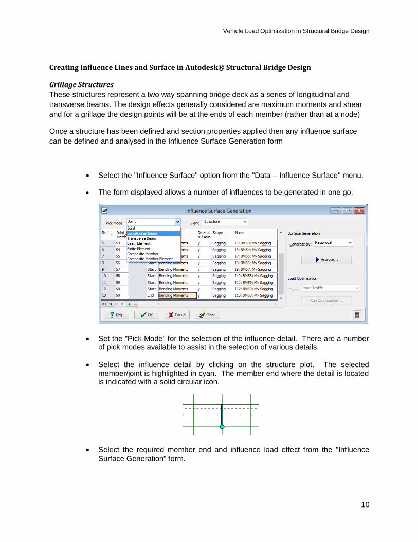
Once a structure has been defined and section properties applied then any influence surface
can be defined and analysed in the Influence Surface Generation form
Select the "Influence Surface" option from the "Data – Influence Surface" menu.
The form displayed allows a number of influences to be generated in one go.
Set the "Pick Mode" for the selection of the influence detail. There are a number of pick modes available to assist in the selection of various details.
Select the influence detail by clicking on the structure plot. The selected member/joint is highlighted in cyan. The member end where the detail is located is indicated with a solid circular icon.
Select the required member end and influence load effect from the "Influence Surface Generation" form.
Vehicle Load Optimization in Structural Bridge Design
11
Select any additional details following the same steps. Normally you would only consider influence surfaces of the same type during a single run of Load Optimisation.
Ensure that the analysis method selected is suitable for the detail under consideration and then click on the "Analyse" button to perform the influence surface calculations. Structural Bridge Design will display the status box shown below during the calculations.
When the calculations have been performed a plot showing the first influence surface will be displayed.
To view the influence surface plot for the other details, click on the influence surface name in the "Name" column on the "Influence Surface Generation" form. When there are a number of influence surfaces you can move down the list using the cursor key to display the influence surface plot for each in turn.
Vehicle Load Optimization in Structural Bridge Design
12
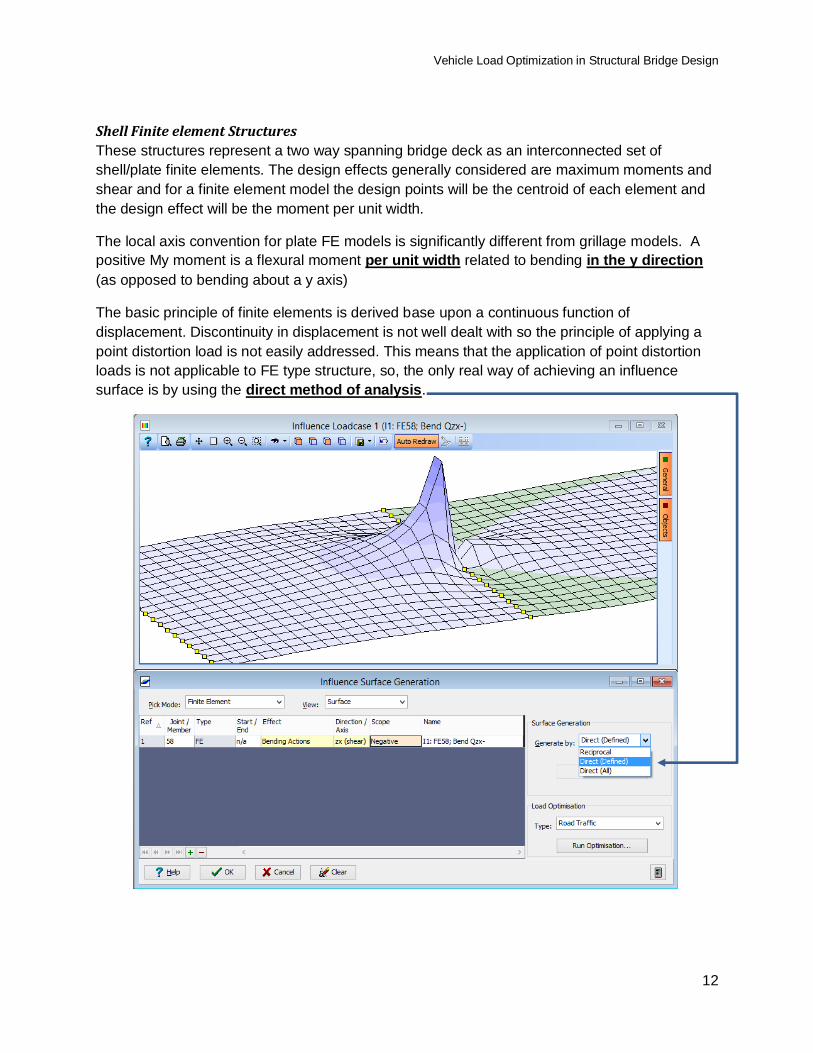
Shell Finite element Structures
These structures represent a two way spanning bridge deck as an interconnected set of
shell/plate finite elements. The design effects generally considered are maximum moments and
shear and for a finite element model the design points will be the centroid of each element and
the design effect will be the moment per unit width.
The local axis convention for plate FE models is significantly different from grillage models. A
positive My moment is a flexural moment per unit width related to bending in the y direction
(as opposed to bending about a y axis)
The basic principle of finite elements is derived base upon a continuous function of
displacement. Discontinuity in displacement is not well dealt with so the principle of applying a
point distortion load is not easily addressed. This means that the application of point distortion
loads is not applicable to FE type structure, so, the only real way of achieving an influence
surface is by using the direct method of analysis.
Vehicle Load Optimization in Structural Bridge Design
13
Code of Practice Requirements for Traffic Loads
AASHTO LRFD
Roadway
The Division of roadway into Design Lanes
The number and widths of design lanes can be determined from the table below
Carriageway width w
in ft
Number of design
Lanes
Width of a
design Lane
12ft < w < 20ft n = 1 w
20ft < w < 24ft n = 2 w/2
24ft < w n = Int(w/12) w/n
Traffic loads occupy a loaded width of 10ft within the lanes and will be located transversely so as to produce the most adverse effect
Multiple presence factors will generally be applied to each lane loaded based upon the number of lanes loaded – as shown in the table below.
Number of loaded
Lanes
Multiple Presence
Factor
1 1.2
2 1.0
3 0.85
>3 0.65
When sidewalks are loaded (on one or both sides) the number of loaded lanes is increased by one
The most onerous combination of number of loaded lanes with factors needs to be considered
Vehicle Load Optimization in Structural Bridge Design
14
AAHTO LRFD Load Models
Consists of three load model components termed as HL93
Lane Load UDL of 0.64KLP over a 10 ft width
A Design Truck (6ft between wheels)
A Design Tandem (6ft transversely between wheels)
Vehicle Load Optimization in Structural Bridge Design
15
Application of Load Models on the Roadway
Each basic design lane is loaded with either
OR
With load only being applied to adverse areas of influence and the truck axle spacing set to a
distance which provides the most onerous results.
In addition, the 10ft loaded width inside the design lane should be positioned transversely to
provide the most onerous results
For the design of negative moments over internal piers and for internal reactions, additional
combinations of loads should be considered
Vehicle Load Optimization in Structural Bridge Design
16
BS5400
Carriageway
The Division of carriageway into notional lanes
The number and widths of notional lanes can be determined from the table below
Carriageway width w in m Number of
notional lanes
Width of a
notional lane
2.50m < w < 5.00m n = 1 2.5m
5.00m < w < 7.50m n = 2 w/2
7.50m < w < 10.95m n = 3 w/3
10.95m < w < 14.60m n = 4 w/4
14.60m < w < 18.25m n = 5 w/5
18.25m < w < 21.90m n = 6 w/6
Lane factors for the uniform lane load are defined to represent the statistical effect of multiple presences of loaded lanes. These are not constant factors but have different values for each lane, depending on which lanes are the most onerous (the most onerous being lane 1). These are defined in Table 14 of BS5400 part 2. The first three lines of this table are shown below:
Loaded length L m
First Lane
Factor 1
Second Lane
Factor 2
Third Lane
Factor 3
Forth and subsequent
lane factors n
0 < L < 20 1 1 0.6 1
20 < L < 40 2 2 0.6 2
40 < L < 50 1.0 1.0 0.6 0.6
1 = 0.27bL but must be less than 1.0
2 = 0.0137{bL(40-L) + 3.65(L-20)}
bL = the notional lane width (m)
Vehicle Load Optimization in Structural Bridge Design
17
Load Models
There are three basic components to the BS5400 load models
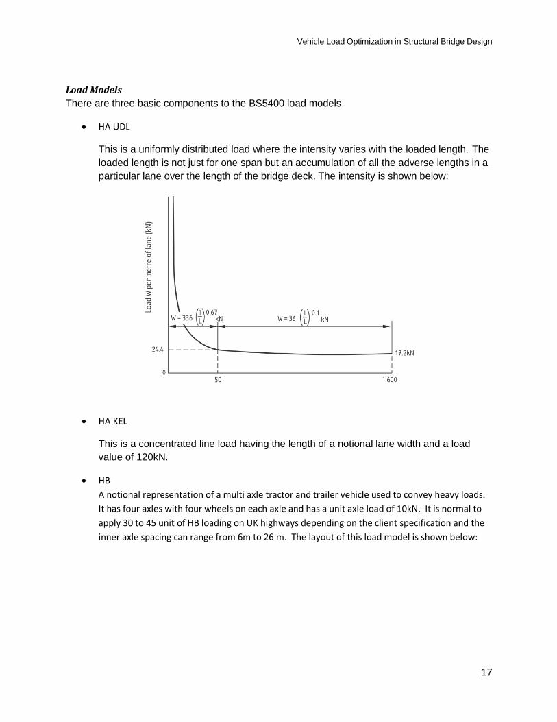
HA UDL
This is a uniformly distributed load where the intensity varies with the loaded length. The
loaded length is not just for one span but an accumulation of all the adverse lengths in a
particular lane over the length of the bridge deck. The intensity is shown below:
HA KEL
This is a concentrated line load having the length of a notional lane width and a load
value of 120kN.
HB
A notional representation of a multi axle tractor and trailer vehicle used to convey heavy loads.
It has four axles with four wheels on each axle and has a unit axle load of 10kN. It is normal to
apply 30 to 45 unit of HB loading on UK highways depending on the client specification and the
inner axle spacing can range from 6m to 26 m. The layout of this load model is shown below:
Vehicle Load Optimization in Structural Bridge Design
18
Application of Load Models on a Carriageway
There are two main combinations of traffic load that we generally consider
1. HA UDL + HA KE loads only
2. N units of HB Load with associated HA UDL + HA KE loads
These may or may not be combined with thermal loads, with different factors, forming
combinations 1 and 3 according to BS5400 part 2
The ULS and SLS load factors for each are different but we will not discuss these here
HA loading only
Simply a UDL and a KEL in each lane but only applied to the adverse areas of
the influence diagram. The intensity of the UDL will depend on the loaded
length.
HB + HB
The deck is loaded with HA(plus KE) first and then an HB load is applied anywhere on
the deck, irrespective of the notional lanes. The HB load displaces the HA + KE load
such that:
In lanes where the HB load is encroaching then the KE load will be removed
In lanes where the HB load is encroaching, then, if the remaining HA width is less
than 2.5m then the UDL will be truncated 25m in front and behind the HB vehicle
in those lanes.
Vehicle Load Optimization in Structural Bridge Design
19
Eurocodes
Carriageway
The Division of Carriageways into Notional Lanes
The number and widths of notional lanes can be determined from the table below
In most other cases there will be a remaining area
Carriageway width w Number of
notional Lanes
Width of a
notional Lane
Width of the
remaining area
w < 5.4m n1 = 1 3m w-3m
5.4m < w < 6m n1 = 2 w/2 0
6m < w n1 = Int(w/3) 3m w-3 x n1
Lanes must be positioned transversely to create the maximum effect.
Any reaming width is known as the “remaining area”
For some load models the intensity of the load is different in each lane so the lanes must be ranked to apply the correct factor.
Vehicle Load Optimization in Structural Bridge Design
20
Load Models
Load Model 1
This model is made up of a tandem system and a UDL in each notional lane and remaining area.
The tandem system comprises of two axles 1.2m apart, each axle having a total load
of QiQik. Each axle load is applied as two wheel loads 2.0m apart and positioned centrally within the lanes. For local verification the tandems in adjacent lanes may be brought closer together with the distance between wheels not less than 0.5m. The wheel contact area is 0.4 by 0.4 m
The UDL has a value of qiqik
is an adjustment factor which is a NDP which is intended to allow representation of different traffic conditions on different roads and in different countries This is for UK NA
Lane Qik
kN
Qi
Table A.2
qik
kN/m2
qi
Table A.2
1 300 1.0 9.0 0.61
2 200 1.0 2.5 2.2
3 100 1.0 2.5 2.2
Other Lanes 0 0 2.5 2.2
Remaining Areas 0 0.0 2.5 2.2
1.2m 2.0m
Direction of
travel
Vehicle Load Optimization in Structural Bridge Design
21
Load Model 2
This model consists of a single axle load with a value of QQak. Q is a NDP with a
recommended value of Q1. For the UK this is 1.0. The value of Qak is 400kN. The load is applied as two wheel loads 2.0m apart.
Load Model 3
Special Vehicles
1. Recommended vehicles and application are given in informative annex A of
EN1991 – 2
2. Most National Annexes have different vehicle configurations and there may be many
of them to consider
2.0m
Direction of
travel
Vehicle Load Optimization in Structural Bridge Design
22
Application of Load Models on Carriageway
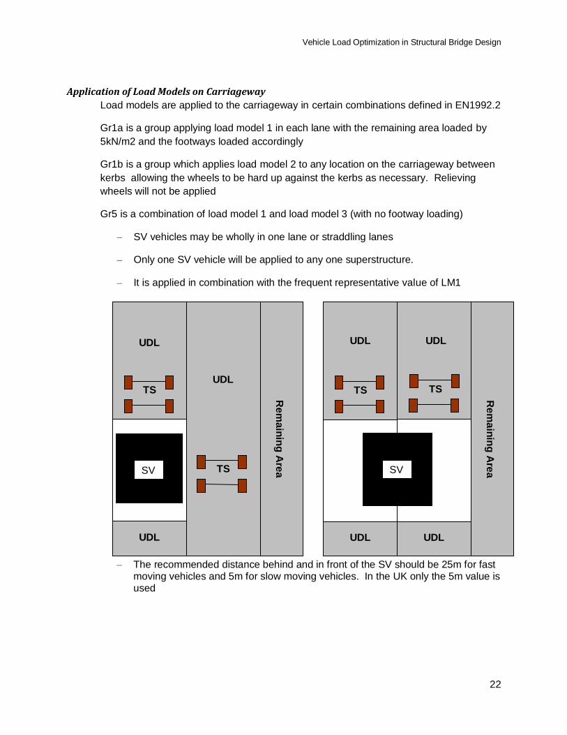
Load models are applied to the carriageway in certain combinations defined in EN1992.2
Gr1a is a group applying load model 1 in each lane with the remaining area loaded by
5kN/m2 and the footways loaded accordingly
Gr1b is a group which applies load model 2 to any location on the carriageway between
kerbs allowing the wheels to be hard up against the kerbs as necessary. Relieving
wheels will not be applied
Gr5 is a combination of load model 1 and load model 3 (with no footway loading)
– SV vehicles may be wholly in one lane or straddling lanes
– Only one SV vehicle will be applied to any one superstructure.
– It is applied in combination with the frequent representative value of LM1
– The recommended distance behind and in front of the SV should be 25m for fast moving vehicles and 5m for slow moving vehicles. In the UK only the 5m value is used
SV
UDL
UDL
UDL
Re
ma
inin
g A
rea
TS
TS SV
UDL UDL
UDL
Re
ma
inin
g A
rea
TS TS
UDL
Vehicle Load Optimization in Structural Bridge Design
23
AS5100
Roadway and Design Lanes
A number of standard design lanes will occupy the width of the roadway.
Each standard design lane will be 3.2m wide. The number and position of standard
design lanes shall be as follows:
n = b/3.2 (rounded down to next integer)
where
n = number of standard design loads
b = width between traffic barriers, in metres, unless specified otherwise
These standard design lanes shall be positioned laterally on the bridge to produce the
most adverse effects.
Any remaining areas will be unloaded
Accompanying lane factors
If more than one lane is loaded, the A160, M1600 or S1600 loading applied to
the additional lanes shall be multiplied by an accompanying lane factor
Standard Design Lane number n Accompanying Lane Factor ALF
1 Lane Loaded 1.0
2 Lanes Loaded 1.0 for first lane , and
0.8 for second lane
3 or More lanes loaded
1.0 for first lane
0.8 for second lane
0.4 for third and subsequent lanes
NOTES:
First lane is the loaded lane giving the largest effect.
Second lane is the loaded lane giving the second largest effect.
Third lane is the loaded lane giving the third largest effect.
The number of standard design lanes loaded and the load patterning (standard design
lane numbering) shall be selected to produce the most adverse effects.
For bridges that support vehicle and pedestrian traffic, the accompanying load factors
shall be applied to both the vehicle and the pedestrian traffic. The total pedestrian load
shall be considered as one standard design lane.
Vehicle Load Optimization in Structural Bridge Design
24
Load Models
W80 wheel load
The W80 wheel load models an individual heavy wheel load. It shall consist of an
80 kN load
A160 axle load
The A160 load models an individual heavy axle of 160kN with two wheels 2.0m apart.
M1600 moving traffic load
S1600 stationary traffic load
Heavy platform load HLP320 or HLP 400
2.0m
Direction
of travel
Vehicle Load Optimization in Structural Bridge Design
25
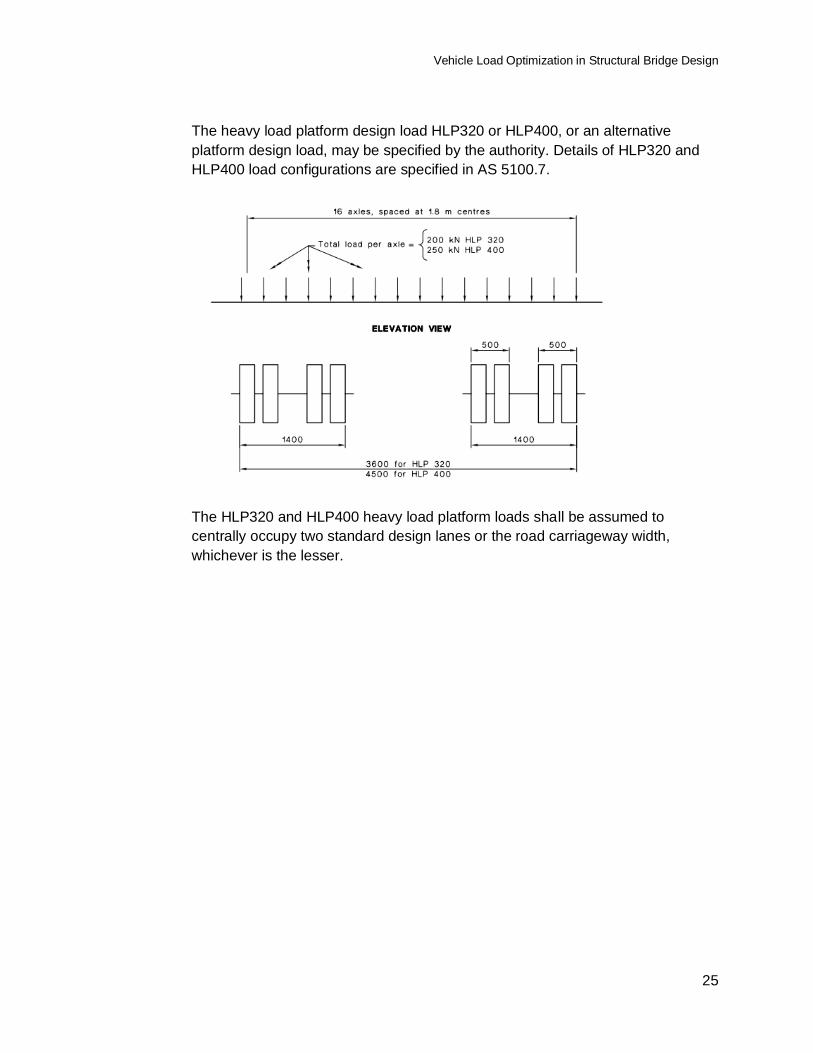
The heavy load platform design load HLP320 or HLP400, or an alternative
platform design load, may be specified by the authority. Details of HLP320 and
HLP400 load configurations are specified in AS 5100.7.
The HLP320 and HLP400 heavy load platform loads shall be assumed to
centrally occupy two standard design lanes or the road carriageway width,
whichever is the lesser.
Vehicle Load Optimization in Structural Bridge Design
26
Application of Load Models on Carriageway
Each of these load conditions should be validated for the worst effect
W80 wheel load
This should be applied anywhere on the roadway surface and to all structural
elements for which the critical load is a single wheel load. It is not associated with
the standard lane but is subject to a dynamic amplification factor
A160
This should be applied in each lane with accompanying lane factors. All options
of number of lanes loaded should be considered and a dynamic load factor
should be applied
M1600 or S1600 moving
The M/S1600 truck shall be positioned centrally within a 3.2 m standard design
lane. The truck position and variable spacing shall be determined so as to
produce the most adverse effects..
The uniformly distributed component of the M/S1600 traffic load shall be
continuous or discontinuous and of any length as may be necessary to
produce the most adverse effects.
Heavy Load Platforms
The heavy load platform loads shall be positioned laterally on a bridge as
specified by the authority. To account for errors in the positioning of actual
vehicles, bridges shall be designed for the effects of the heavy load platform
loads positioned up to 1.0 m laterally in either direction from the specified
position.
Where the two standard design lanes containing the heavy load platform
loads are positioned such that one or more design traffic lanes are unobstructed,
then a load of half of either the M1600 moving traffic load or the S1600
stationary traffic load, to create the worst effect, shall be placed in those
lanes, unless the authority specifies otherwise.
Vehicle Load Optimization in Structural Bridge Design
27
Traffic Load Optimisation in Autodesk® Structural Bridge Design
General Procedure
Selecting a set of influences
Influences can be analysed one by one but it is more usual to specify a group that relate
to a particular set of design features for a particular component of the structure. For
example, the moment analysis for all points along a girder in a particular span.
Once the influences surfaces have been produced we open the Load Optimisation form
by clicking on the “Run Optimisation” button
Setting the parameter
Once the Optimisation form is open it is necessary to inspect the default parameters and
make changes were necessary.
Most of the parameters will only need changing once as the details are stored in the data
file.
Many of the parameters are design code specific and the form may look different for
each standard, but, the form is generally arranged so that certain parameters are in
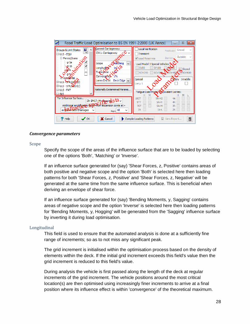
groups, as shown below.
Vehicle Load Optimization in Structural Bridge Design
28
Convergence parameters
Scope
Specify the scope of the areas of the influence surface that are to be loaded by selecting
one of the options 'Both', 'Matching' or 'Inverse'.
If an influence surface generated for (say) 'Shear Forces, z, Positive' contains areas of
both positive and negative scope and the option 'Both' is selected here then loading
patterns for both 'Shear Forces, z, Positive' and 'Shear Forces, z, Negative' will be
generated at the same time from the same influence surface. This is beneficial when
deriving an envelope of shear force.
If an influence surface generated for (say) 'Bending Moments, y, Sagging' contains
areas of negative scope and the option 'Inverse' is selected here then loading patterns
for 'Bending Moments, y, Hogging' will be generated from the 'Sagging' influence surface
by inverting it during load optimisation.
Longitudinal
This field is used to ensure that the automated analysis is done at a sufficiently fine
range of increments; so as to not miss any significant peak.
The grid increment is initialised within the optimisation process based on the density of
elements within the deck. If the initial grid increment exceeds this field's value then the
grid increment is reduced to this field's value.
During analysis the vehicle is first passed along the length of the deck at regular
increments of the grid increment. The vehicle positions around the most critical
location(s) are then optimised using increasingly finer increments to arrive at a final
position where its influence effect is within 'convergence' of the theoretical maximum.
Vehicle Load Optimization in Structural Bridge Design
29
The grid increment is also used to divide lanes into segments; each of which is
individually assessed (to be net adverse or relieving) to determine which parts of the
lane should be loaded by uniformly distributed load.
Increasing this field's value may speed execution in some cases but generally has no
effect. Reducing its value can force finer optimisation and is a potential workaround to
some numeric problems.
Transverse
This is similar to the longitudinal increment but related to the transverse positioning of
vehicles and lanes.
Convergence
This value controls the accuracy for the refinement process of placing a vehicle or lane
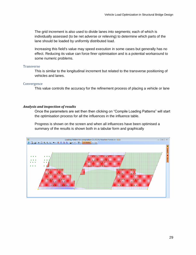
Analysis and inspection of results
Once the parameters are set then then clicking on “Compile Loading Patterns” will start
the optimisation process for all the influences in the influence table.
Progress is shown on the screen and when all influences have been optimised a
summary of the results is shown both in a tabular form and graphically
Vehicle Load Optimization in Structural Bridge Design
30
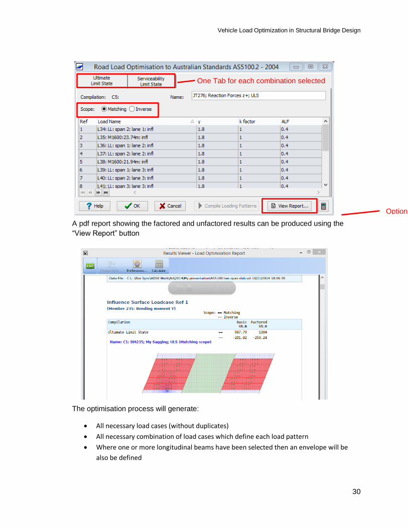
A pdf report showing the factored and unfactored results can be produced using the
“View Report” button
The optimisation process will generate:
All necessary load cases (without duplicates)
All necessary combination of load cases which define each load pattern
Where one or more longitudinal beams have been selected then an envelope will be
also be defined
Options if Scope set to “Both”
One Tab for each combination selected
Vehicle Load Optimization in Structural Bridge Design
31
Parameters for AASHTO Bridges
Select Design vehicles
One or more Design vehicles should be selected. The “Double vehicles” options will
only be selectable if the “Double Design Heh:” is of an appropriate type for one or more
influences.
Fatigue
If one of the Fatigue Limit State combinations is selected then a couple of AASHTO
clauses come into effect related to orthotropic decks and whether they have “rib-to-deck”
welds
Dynamic Allowances
The dynamic allowance given in article 3.6.2.1 can be modified according to article
4.7.2.1 and these fields allow the DLA to be changed for each of the design vehicles
Deck Overhang
This option should be ticked on an influence by influence basis, depending on whether
the influence in question is related to a deck overhang member. This affects the
transverse ranges for the “Design Vehicle” in accordance with Article 3.6.1.3.1
Vehicle Load Optimization in Structural Bridge Design
32
Parameters for BS5400 Bridges
By default the standard HA curve is used but a user defined loading curve can be
defined
30 Units of HB are defined by default with a variable inner axle. The units can be
changed as well as fixing the variable axle spacing to a set value.
KE loads will be generally orientated so that they are perpendicular to the direction of
traffic flow. For certain design details (eg cantilever slabs) the KE load is to be
orientated to give the worst effect.
The effect of a cusped shape of influence line will affect the loaded length used to
determine the HA load intensity
Loaded length
Vehicle Load Optimization in Structural Bridge Design
33
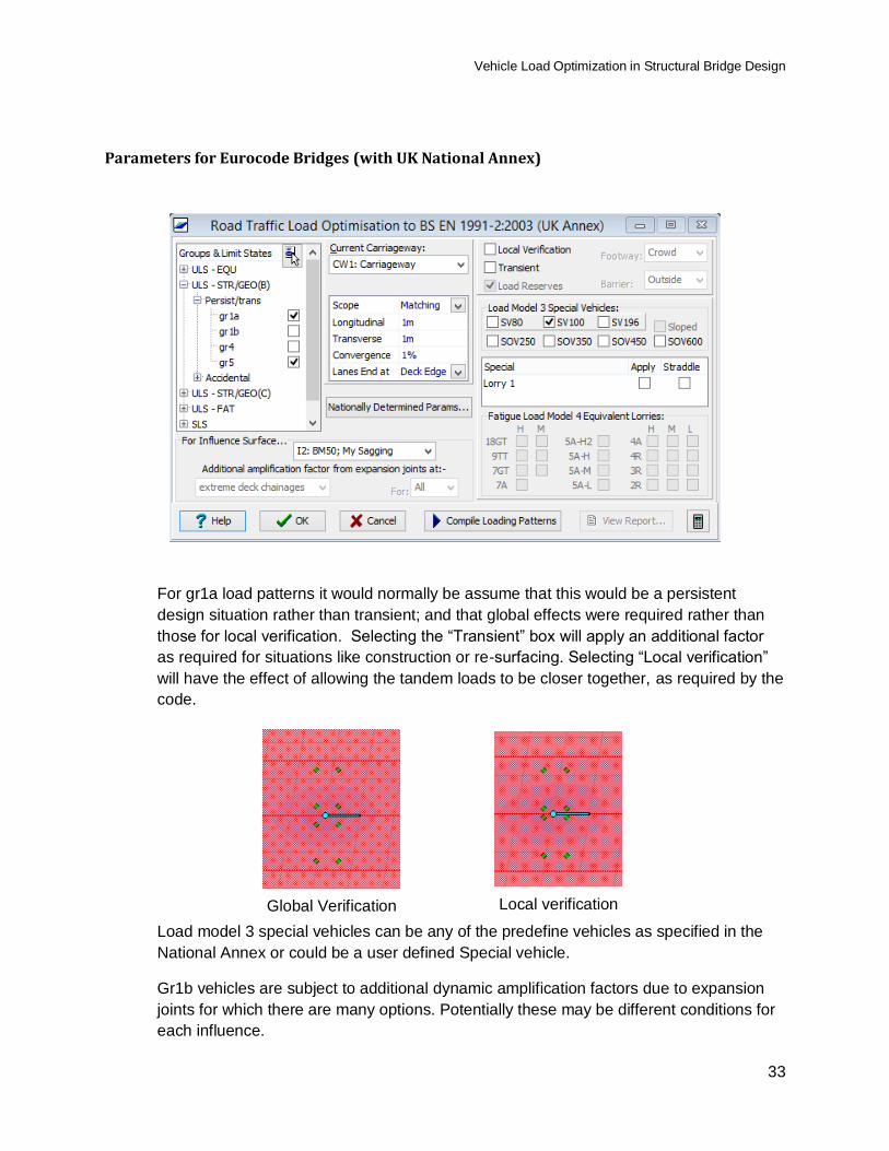
Parameters for Eurocode Bridges (with UK National Annex)
For gr1a load patterns it would normally be assume that this would be a persistent
design situation rather than transient; and that global effects were required rather than
those for local verification. Selecting the “Transient” box will apply an additional factor
as required for situations like construction or re-surfacing. Selecting “Local verification”
will have the effect of allowing the tandem loads to be closer together, as required by the
code.
Global Verification
Local verification
Load model 3 special vehicles can be any of the predefine vehicles as specified in the
National Annex or could be a user defined Special vehicle.
Gr1b vehicles are subject to additional dynamic amplification factors due to expansion
joints for which there are many options. Potentially these may be different conditions for
each influence.
Vehicle Load Optimization in Structural Bridge Design
34
Parameters for AS5100 Bridges
Vehicle selection
Each vehicle here will be considered in the optimisation and the most adverse effect
used to produce the traffic load pattern. In general, W80 and A160 will be used for local
verification.
HLP Offsets
If an HLP load is selected it will generally be applied centrally over two design lanes. If
the line of the HLP vehicle is stipulated then this can be defined as an offset to the
carriageway design line by selecting the “Force Offset” option
Dynamic Load Allowance
The default Dynamic Load Allowance is defined in table 6.7.2 of AS5100.2 but there is
provision here to make adjustments if necessary.
Straddling ALF
Design lanes which are occupied by Special Vehicles and Convoys (with straddle
checked) and HLPs have an Accompanying Lane Factor (ALF) of 1.0. This field defines
the ALF that is to be applied to all other lanes (including footways).
Walkway options
It is important to understand clauses 7.1 and 7.2 of AS5100 part 2 to make a selection in
these fieds which will affect how footway loading will be applied
Vehicle Load Optimization in Structural Bridge Design
35
How Optimisation process fits into general bridge analysis workflow
General Procedure
Autodesk Structural Bridge Design provides an integrated workflow for the design of small to
medium sized deck type bridges. This general process will be shown in a demonstration and
can also be found in the Examples manual for the software. This pdf manual is accessible from
the software under the “Help” menu and the process will be found in any of the complete
examples in section 10.
The general procure headings are shown below
Creation of structural components
Building structure with components
Non-traffic Loading analysis
Load optimisation for a specific girder (or property set)