Australian Design Rule 82/00 Engine Immobilisers 1 Vehicle Standard (Australian Design Rule 82/00 – Engine Immobilisers) 2006 I, JAMES ERIC LLOYD, Minister for Local Government, Territories and Roads, determine this vehicle standard under subsection 7 (1) of the Motor Vehicle Standards Act 1989. Dated 8 August 2006 [SIGNED] James Eric Lloyd Minister for Local Government, Territories and Roads Federal Register of Legislative Instruments F2006L02665
Transcript
Australian Design Rule 82/00 Engine Immobilisers 1
Vehicle Standard (Australian Design Rule 82/00 – Engine Immobilisers) 2006
I, JAMES ERIC LLOYD, Minister for Local Government, Territories and Roads, determine this vehicle standard under subsection 7 (1) of the Motor Vehicle Standards Act 1989. Dated 8 August 2006 [SIGNED] James Eric Lloyd Minister for Local Government, Territories and Roads
Federal Register of Legislative Instruments F2006L02665
Australian Design Rule 82/00 Engine Immobilisers 2
Federal Register of Legislative Instruments F2006L02665
Australian Design Rule 82/00 Engine Immobilisers 3
0. LEGISLATIVE PROVISIONS 0.1. NAME OF STANDARD
0.1.1. This Standard is the Vehicle Standard (Australian Design Rule 82/00 – Engine Immobilisers) 2006.
0.1.2. This Standard may also be cited as Australian Design Rule 82/00 — Engine Immobilisers.
0.2. COMMENCEMENT
0.2.1. This Standard commences on the day after it is registered.
0.3. REPEAL
0.3.1. This Standard repeals each vehicle standard with the name Australian Design Rule 82/00 — Engine Immobilisers that is:
(a) made under section 7 of the Motor Vehicles Standard Act 1989; and
(b) in force at the commencement of this Standard.
0.3.2. This Standard also repeals each instrument made under section 7 of the Motor Vehicles Standard Act 1989 that creates a vehicle standard with the name Australian Design Rule 82/00 — Engine Immobilisers, if there are no other vehicle standards created by that instrument, or amendments to vehicle standards made by that instrument, that are still in force at the commencement of this Standard.
1. SCOPE This Standard prescribes the requirements for engine immobilising devices which are intended to be fitted to vehicles so as to prevent the vehicle being driven away powered by its own engine.
2. APPLICABILITY 2.1. This Standard applies to the design and construction of vehicles as set out in
the table below.
2.2. Those vehicles must be equipped with an engine immobilising device complying with the relevant requirements of this national standard, except for
2.2.1. Vehicles with 24 V electrical systems (see paragraph 1.3 of Appendix A and the footnote on page 1 of Appendix A).
Federal Register of Legislative Instruments F2006L02665
Australian Design Rule 82/00 Engine Immobilisers 4
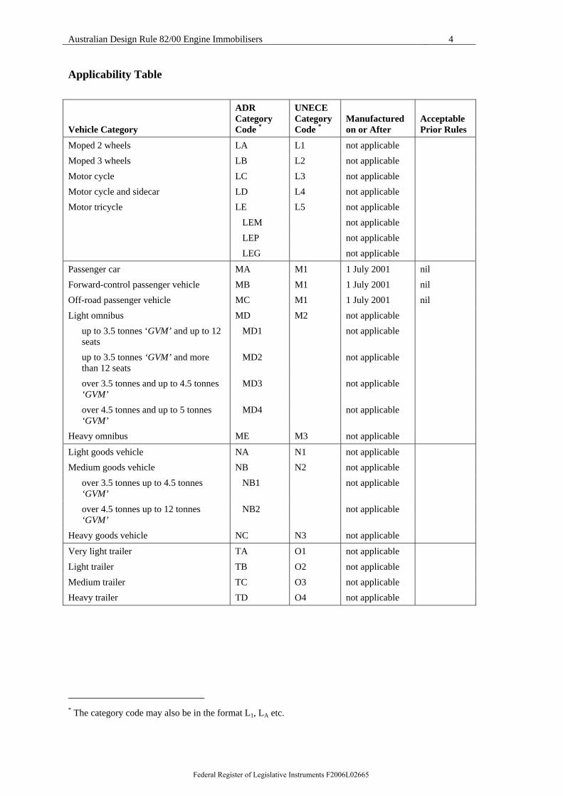
Applicability Table
Vehicle Category
ADR Category Code *
UNECE Category Code *
Manufactured on or After
Acceptable Prior Rules
Moped 2 wheels LA L1 not applicable Moped 3 wheels LB L2 not applicable Motor cycle LC L3 not applicable Motor cycle and sidecar LD L4 not applicable Motor tricycle LE L5 not applicable LEM not applicable LEP not applicable LEG not applicable
Passenger car MA M1 1 July 2001 nil Forward-control passenger vehicle MB M1 1 July 2001 nil Off-road passenger vehicle MC M1 1 July 2001 nil Light omnibus MD M2 not applicable up to 3.5 tonnes ‘GVM’ and up to 12
seats MD1 not applicable
up to 3.5 tonnes ‘GVM’ and more than 12 seats
MD2 not applicable
over 3.5 tonnes and up to 4.5 tonnes ‘GVM’
MD3 not applicable
over 4.5 tonnes and up to 5 tonnes ‘GVM’
MD4 not applicable
Heavy omnibus ME M3 not applicable
Light goods vehicle NA N1 not applicable Medium goods vehicle NB N2 not applicable over 3.5 tonnes up to 4.5 tonnes
‘GVM’ NB1 not applicable
over 4.5 tonnes up to 12 tonnes ‘GVM’
NB2 not applicable
Heavy goods vehicle NC N3 not applicable
Very light trailer TA O1 not applicable Light trailer TB O2 not applicable Medium trailer TC O3 not applicable Heavy trailer TD O4 not applicable
* The category code may also be in the format L1, LA etc.
Federal Register of Legislative Instruments F2006L02665
Australian Design Rule 82/00 Engine Immobilisers 5
3. DEFINITIONS For vehicle categories, definitions and meanings used in this Australian Design Rule, refer to:
3.1. Vehicle Standard (Australian Design Rule - Definitions and Vehicle Categories) 2005.
3.2. Definitions in Part III of Regulation No. 97 adopted by the United Nations Economic Commission for Europe.
4. REQUIREMENTS For the purposes of this Australian Design Rule, engine immobilising devices fitted to vehicles shall comply with:
4.1. The technical requirements adopted by the United Nations - Economic Commission for Europe in Part III of Regulation No. 97 - UNIFORM PROVISIONS CONCERNING THE APPROVAL OF VEHICLE ALARM SYSTEMS (VAS) AND OF MOTOR VEHICLES WITH REGARD TO THEIR ALARM SYSTEMS (AS) which incorporates the 01 series of amendments, except as varied by section 5 Exemptions And Alternative Procedures and section 6 Supplementary General Requirements, of this standard.
5. EXEMPTIONS AND ALTERNATIVE PROCEDURES Compliance with the following parts, sections and annexes of Appendix A is not required for the purposes of this standard. Sections 2 to 6 and 8 to 13 of Part 1 except where directly or indirectly invoked by Part III, paragraph 7.2.11, all sections of Part II, the following administrative provisions of Part III and the annexes listed below:
Section 27 Application for approval of an immobiliser
Section 28 Application for approval of a vehicle
Section 29 Approval of an immobiliser
Section 30 Approval of vehicle
Section 34 Instructions - Paragraphs 34.1 to 34.3
Section 35 Modification of the immobiliser type or vehicle type and extension of approval
Section 36 Conformity of production
Section 37 Penalties for non-conformity of production
Section 38 Production definitely discontinued
Section 39 Names and addresses of technical services responsible for conducting approval tests, and of administrative departments
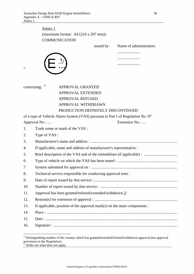
Annexes Annex 1 Communication concerning the approval (or refusal or
withdrawal of approval or production definitely discontinued)
Federal Register of Legislative Instruments F2006L02665
Australian Design Rule 82/00 Engine Immobilisers 6
of a type of vehicle alarm system pursuant to Part I of Regulation No. 97
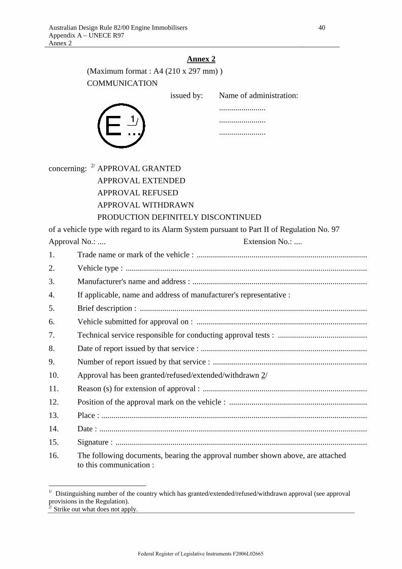
Annex 2 Communication concerning the approval (or refusal or withdrawal of approval or production definitely discontinued) of a vehicle type. with regard to its alarm system pursuant to Part II of Regulation No. 97
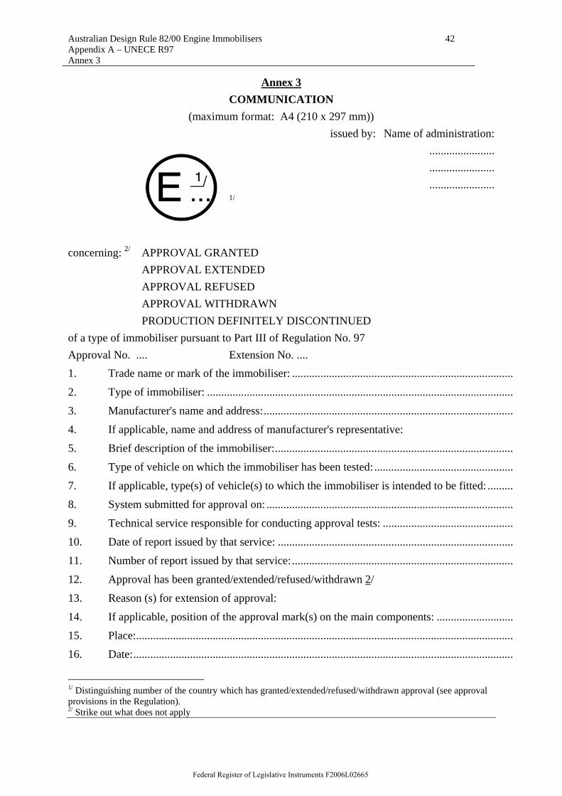
Annex 3 Communication concerning the approval (or refusal or withdrawal of approval or production definitely discontinued) of a type of immobilizer pursuant to Part Ill of Regulation No. 97
Annex 4 Communication concerning the approval (or refusal or withdrawal of approval or production definitely discontinued) of a vehicle type with regard to its immobilizer pursuant to Part III of Regulation No. 97
Annex 5 Arrangements of approval marks
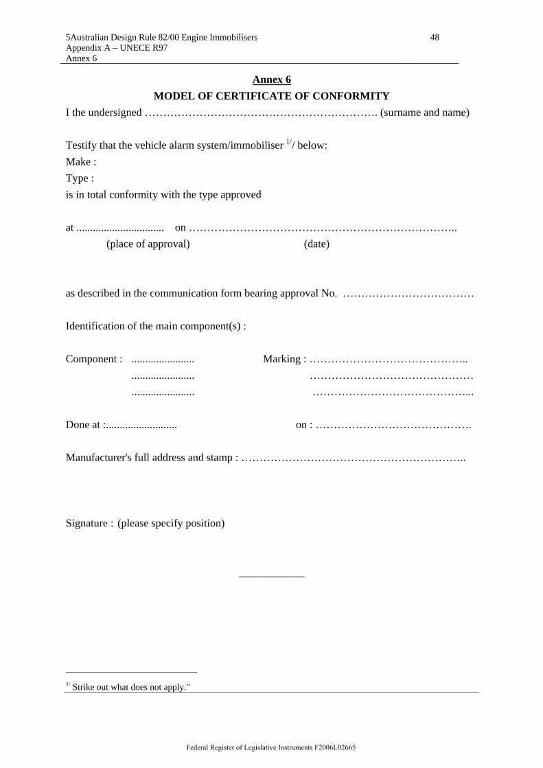
Annex 6 Model of certificate of conformity
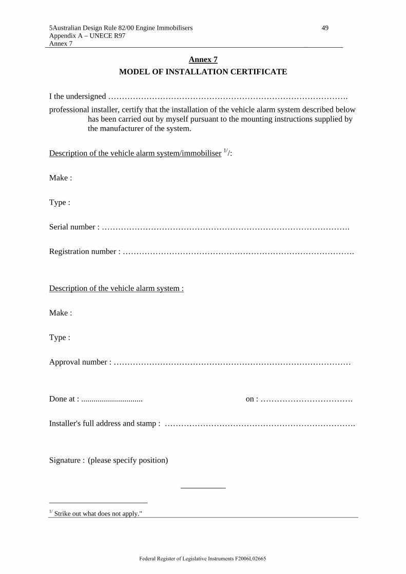
Annex 7 Model of installation certificate
Annex 8 Tests for systems for the protection of the passenger compartment.
6. SUPPLEMENTARY GENERAL REQUIREMENTS
6.1. Whereas paragraph 7.1.1 of Appendix A nominates -40° C as the lower temperature limit for climatic conditions testing, -20 ° C will be deemed to be acceptable for the purposes of this standard.
6.2. Whereas paragraph 7.2.2.1 of Appendix A nominates -40± 2° C as the test temperature, -20 ± 2° C will be deemed to be acceptable for the purposes of this standard.
6.3. Electromagnetic compatibility (EMC) requirements may be met by the tests prescribed in Annex 9 or alternatively according to the Voluntary Code of Practice for Electromagnetic Compatibility of Motor Vehicles, April 1998 published by the Federal Chamber of Automotive Industries, GPO Box 313, Canberra, ACT 2601, Australia.
6.4. An engine immobiliser that can meet the required degrees of protection nominated in paragraph 7.1.2 of Appendix A in the as installed position will be deemed to comply with the requirements of this Standard.
6.5. AS 1939 -1990 - Degrees of protection provided by enclosures for electrical equipment (IP Code) may be used as an alternative in place of IEC 529-1989 (referenced in 7.1.2 and 7.2.3 of Appendix A).
6.6. For the purposes of this Australian Design Rule, where the immobiliser is combined with other vehicle systems or integrated into them (eg engine management, alarm systems), the short circuit safety test requirements of paragraph 7.2.6 of Appendix A only apply to the electrical connections of the immobiliser.
Federal Register of Legislative Instruments F2006L02665
Australian Design Rule 82/00 Engine Immobilisers 7
7. ALTERNATIVE STANDARDS 7.1. The technical requirements in Part III, of United Nations - Economic
Commission for Europe Regulation No. 97 - "UNIFORM PROVISIONS CONCERNING THE APPROVAL OF VEHICLE ALARM SYSTEMS (VAS) AND OF MOTOR VEHICLES WITH REGARD TO THEIR ALARM SYSTEMS (AS)", incorporating supplement 1 and corrigenda 1 to the 00 series of amendments, are deemed to be equivalent to the technical requirements of this standard.
7.2. The technical requirements in Part III, of United Nations - Economic Commission for Europe Regulation No. 97 - "UNIFORM PROVISIONS CONCERNING THE APPROVAL OF VEHICLE ALARM SYSTEMS (VAS) AND OF MOTOR VEHICLES WITH REGARD TO THEIR ALARM SYSTEMS (AS)", incorporating the 01series of amendments, are deemed to be equivalent to the technical requirements of this standard.
7.3. UNECE Regulation 116 “Uniform Technical Prescriptions Concerning the Protection of Motor Vehicles Against Unauthorized Use”, incorporating the 00 series of amendments.
8. NOTES 8.1. Appendix A is a copy of the United Nations - Economic Commission for
Europe Regulation No. 97 -UNIFORM PROVISIONS CONCERNING THE APPROVAL OF VEHICLE ALARM SYSTEMS (VAS) AND OF MOTOR VEHICLES WITH REGARD TO THEIR ALARM SYSTEMS (AS)2 which incorporates the 01 series of amendments.
2 United Nations - Economic Commission for Europe Document Reference: E/ECE/324/E/ECE/TRANS/505/Add.96/Amend. 2
Federal Register of Legislative Instruments F2006L02665
Australian Design Rule 82/00 Engine Immobilisers Appendix A – UNECE R97
8
APPENDIX A
AGREEMENT
CONCERNING THE ADOPTION OF UNIFORM TECHNICAL PRESCRIPTIONS FOR WHEELED VEHICLES, EQUIPMENT AND PARTS WHICH
CAN BE FITTED AND/OR BE USED ON WHEELED VEHICLES AND THE CONDITIONS FOR RECIPROCAL RECOGNITION OF APPROVALS GRANTED
ON THE BASIS OF THESE PRESCRIPTIONS */
(Revision 2, including the amendments entered into force on 16 October 1995)
__________
Addendum 96: Regulation No. 97
Incorporating: Supplement 1 to the original version of the Regulation - Date of entry into force: 2 October 1997 Corrigendum 1 to the original version of the Regulation subject of Depositary Notification C.N.45.1998.TREATIES-26 dated 6 March 1998 01 series of amendments -
Date of entry into force: 13 January 2000
UNIFORM PROVISIONS CONCERNING THE APPROVAL OF VEHICLE ALARM SYSTEMS (VAS) AND OF MOTOR VEHICLES WITH REGARD TO THEIR ALARM SYSTEMS (AS)
__________
UNITED NATIONS */ Former title of the Agreement: Agreement Concerning the Adoption of Uniform Conditions of Approval and Reciprocal Recognition of Approval for Motor Vehicle Equipment and Parts, done at Geneva on 20 March 1958.
Federal Register of Legislative Instruments F2006L02665
Australian Design Rule 82/00 Engine Immobilisers Appendix A – UNECE R97
9
Regulation No. 97 UNIFORM PROVISIONS CONCERNING THE APPROVAL OF VEHICLE ALARM
SYSTEMS (VAS) AND OF MOTOR VEHICLES WITH REGARD TO THEIR ALARM SYSTEMS (AS)
CONTENTS
1. Scope ................................................. Part I - Approval of vehicle alarm systems 2. Definitions ........................................... 3. Application for approval of VAS ....................... 4. Approval .............................................. 5. General specifications ................................ 6. Particular specifications ............................. 7. Operation parameters and test conditions .............. 8. Instructions .......................................... 9. Modification of the VAS type and extension of approval ............................... 10. Conformity of production .............................. 11. Penalties for non-conformity of production ............ 12. Production definitely discontinued .................... 13. Names and addresses of technical services responsible for conducting
approval tests, and of administrative departments ........................ Part II - Approval of a vehicle with regard to its alarm system 14. Definitions ........................................... 15. Application for approval .............................. 16. Approval .............................................. 17. General specifications ................................ 18. Particular specifications ............................. 19. Test conditions ....................................... 20. Instructions .......................................... 21. Modification of the vehicle type and extension of approval ...............................
22. Conformity of production .............................. 23. Penalties for non-conformity of production ............ 24. Production definitely discontinued .................... 25. Names and addresses of technical services responsible for conducting
approval tests, and of administrative departments ........................ Part III - Approval of immobilisers and approval of a vehicle with regard to its
immobiliser 26. Definitions
Federal Register of Legislative Instruments F2006L02665
Australian Design Rule 82/00 Engine Immobilisers Appendix A – UNECE R97
10
27. Application for approval of an immobiliser 28. Application for approval of a vehicle 29. Approval of an immobiliser 30. Approval of a vehicle 31. General specifications 32. Particular specifications 33. Operation parameters and test conditions 34. Instructions 35. Modifications of the immobiliser type or vehicle type and extension of approval 36. Conformity of production 37. Penalties for non-conformity of production 38. Production definitely discontinued 39. Names and addresses of technical services responsible for conducting approval
tests, and of administrative departments ANNEXES Annex 1- Communication concerning the approval or extension or refusal or withdrawal of
approval or production definitely discontinued of a type of Vehicle Alarm System (VAS) pursuant to Part I of Regulation No. 97
Annex 2- Communication concerning the approval or extension or refusal or withdrawal of approval or production definitely discontinued of a vehicle type with regard to its Alarm System pursuant to Part II of Regulation No. 97
Annex 3- Communication concerning the approval or extension or refusal or withdrawal of approval or production definitely discontinued of a type of immobiliser pursuant to Part III or Regulation No. 97
Annex 4- Communication concerning the approval or extension or refusal or withdrawal of approval or production definitely discontinued of a vehicle type with regard to its immobiliser pursuant to Part III of Regulation No. 97
Annex 5- Arrangements of approval marks Annex 6- Model of certificate of conformity Annex 7- Model of installation certificate Annex 8- Test of systems for the protection of the passenger compartment Annex 9- Electromagnetic compatibility Annex 10- Specifications for mechanical key switches
_______________
Federal Register of Legislative Instruments F2006L02665
Australian Design Rule 82/00 Engine Immobilisers Appendix A – UNECE R97
11
1. SCOPE This regulation applies to : 1.1. PART 1 : Vehicle Alarm Systems (VAS) which are intended to be permanently
fitted to vehicles of category M1 and those of category N1 with a maximum mass of not more than 2 tonnes. */
1.2. Part II: Vehicles of category M1, and those of category N1 with a maximum mass of not more than 2 tonnes, with regard to their alarm system(s) (AS). */
1.3. Part III: Immobilisers and vehicles of category M1 and vehicles of category N1 with a maximum mass of not more than 2 tonnes with regard to immobilisers. */
PART I - APPROVAL OF VEHICLE ALARM SYSTEMS 2. DEFINITIONS For the purpose of Part I of this Regulation, 2.1. "Vehicle alarm system" (VAS) means a system intended for installation on (a)
type(s) of vehicle(s), designed to indicate intrusion into or interference with the vehicle; these systems may provide additional protection against unauthorised use of the vehicle;
2.2. "Sensor" means a device which senses a change which could be caused by in-trusion into or interference with a vehicle;
2.3. "Warning device" means a device indicating that intrusion into or interference has occurred;
2.4. "Control equipment" means equipment necessary for the setting, unsetting and testing of a VAS and for sending an alarm condition to warning devices;
2.5. "Set" means the state of a VAS in which an alarm condition can be transmitted to warning devices;
2.6. "Unset" means the state of a VAS in which an alarm condition cannot be trans-mitted to warning devices;
2.7. "Key" means any device designed and constructed to provide a method of oper-ating a locking system which is designed and constructed to be operated only by that device;
2.8. "Type of Vehicle Alarm System" means systems which do not differ significantly in such essential aspects as :
the manufacturer's trade name or mark, the kind of sensor, the kind of warning device, the kind of control equipment; 2.9. "Approval of a Vehicle Alarm System" means the approval of a type of VAS with
respect to the requirements laid down in paragraphs 5, 6 and 7 below. 2.10. "Immobiliser" means a device which is intended to prevent the vehicle being
driven away powered by its own engine. 2.11. "Panic Alarm" means a device which enables a person to use an alarm, installed
on the vehicle, to summon assistance in an emergency.
*/ Only vehicles with 12 volts electrical systems are considered.;
Federal Register of Legislative Instruments F2006L02665
Australian Design Rule 82/00 Engine Immobilisers Appendix A – UNECE R97
12
3. APPLICATION FOR APPROVAL OF VAS 3.1. The application for approval of a VAS shall be submitted by the manufacturer of
the VAS or by his duly accredited representative. 3.2. For each type of VAS the application must be accompanied by : 3.2.1. Documentation in triplicate giving a description of the technical characteristics of
the VAS and the method of its installation; 3.2.2. Three samples of the type of VAS with all its components. Each of the main
components must be clearly and indelibly marked with the applicant's trade name or mark and the type designation of that component.
3.2.3. (A) vehicle(s) fitted with the VAS to be type-approved, chosen by the applicant in agreement with the technical service responsible for conducting approval tests.
3.2.4. Instructions in triplicate in accordance with paragraph 8 below. 4. APPROVAL 4.1. If the VAS submitted for approval pursuant to this Regulation meets the require-
ments of paragraphs 5, 6 and 7 below, approval of that type of VAS shall be granted.
4.2. An approval number of which the first two digits (currently 01 for the 01 series of amendments) shall indicate the series of amendments incorporating the most recent major technical amendments made to the Regulation at the time of issue of the approval. The same Contracting Party may not assign the same number to another type of VAS.
4.3. Notice of approval or of extension or of refusal of approval of a type of VAS pursuant to this Regulation shall be communicated to the Contracting Parties to the Agreement applying this Regulation by means of a form conforming to the model in Annex 1 to this Regulation.
4.4. There shall be affixed, conspicuously and in a readily accessible place specified on the approval form, to the main component(s) of the VAS conforming to a type of VAS approved under this Regulation, an international approval mark consisting of :
4.4.1. A circle surrounding the letter "E" followed by the distinguishing number of the country which has granted approval 1/;
4.4.2. The number of this Regulation, followed by the letter "R", a symbol "A" or "I" or "AI" indicating if the system is a vehicle alarm system or an immobiliser or a combination of both, a dash and the approval number in the vicinity of the circle prescribed in paragraph 4.4.1.
1/ 1 for Germany, 2 for France, 3 for Italy, 4 for the Netherlands, 5 for Sweden, 6 for Belgium, 7 for Hungary, 8 for the Czech Republic, 9 for Spain, 10 for Yugoslavia, 11 for the United Kingdom, 12 for Austria, 13 for Luxembourg, 14 for Switzerland, 15 (vacant), 16 for Norway, 17 for Finland, 18 for Denmark, 19 for Roma-nia, 20 for Poland, 21 for Portugal, 22 for the Russian Federation, 23 for Greece, 24 for Ireland, 25 for Croatia, 26 for Slovenia, 27 for Slovakia, 28 for Belarus, 29 for Estonia, 30 (vacant), 31 for Bosnia and Herzegovina, 32 for Latvia, 33 (vacant), 34 for Bulgaria, 35-36 (vacant), 37 for Turkey, 38-39 (vacant), 40 for The former Yugoslav Republic of Macedonia, 41 (vacant), 42 for the European Community (Approvals are granted by its Member States using their respective ECE symbol), 43 for Japan, 44 (vacant), 45 for Australia and 46 for Ukraine. Subsequent numbers shall be assigned to other countries in the chronological order in which they ratify or accede to the Agreement Concerning the Adoption of Uniform Technical Prescriptions for Wheeled Vehicles, Equipment and Parts which can be Fitted and/or be Used on Wheeled Vehicles and the Conditions for Reciprocal Recognition of Approvals Granted on the Basis of these Prescriptions, and the numbers thus assigned shall be communicated by the Secretary-General of the United Nations to the Contracting Parties to the Agreement.
Federal Register of Legislative Instruments F2006L02665
Australian Design Rule 82/00 Engine Immobilisers Appendix A – UNECE R97
13
4.4.3. The approval mark shall be clearly legible and indelible. 4.4.4. Annex 5 to this Regulation gives examples of arrangements of approval marks. 4.5. As an alternative to the approval mark described in paragraph 4.4. above, a cer-
tificate of conformity shall be issued for every VAS offered for sale. Where a VAS manufacturer supplies an approved unmarked VAS to a vehicle
manufacturer, for fitment by that manufacturer as original equipment for a vehicle model or range of vehicle models, the VAS manufacturer shall supply a number of copies of the certificate of conformity to the vehicle manufacturer, sufficient for that manufacturer to obtain the vehicle approval to Part II of this Regulation.
If the VAS is made up of separate components, its main component(s) shall bear a reference mark and the certificate of conformity shall provide a list of such reference marks.
A model of the certificate of conformity is given in Annex 6 to this Regulation. 5. GENERAL SPECIFICATIONS 5.1. VAS shall, in the event of intrusion into or interference with a vehicle, provide a
warning signal. The warning signal shall be audible and in addition may include optical warning
devices, or be a radio alarm or any combination of the above. 5.2. VASs shall be designed, constructed and installed in such a way that the vehicle
when equipped shall continue to comply with the relevant technical requirements, especially with regard to electromagnetic compatibility (EMC).
5.3. If the VAS includes the possibility of a radio transmission, e.g. for setting or unsetting of the alarm or for alarm transmission, it shall comply with the relevant ETSI Standards. 2/ The frequency must be 433.92 MHz and the maximum radiated power 25 mW.
5.4. The installation of a VAS in a vehicle shall not be capable of influencing the vehicle's performance (in the unset state), or its safe operation.
5.5. The VAS and components thereof shall not activate inadvertently, particularly whilst the engine is in its running mode.
5.6. Failure of the VAS, or failure of its electrical supply shall not affect the safe operation of the vehicle.
5.7. The VAS, its components and the parts controlled by them shall be designed, built and installed in such a way as to minimise the risk for anyone to make them inoperable or to destroy them rapidly and without calling attention, e.g. using low-cost,
easily-concealed tools, equipment or fabrications readily available to the public at large.
5.8. The means of setting and unsetting of the VAS shall be designed in such a way that it does not invalidate the requirements of Regulation No. 18. Electrical connections to components covered by this Regulation are allowed.
5.9. The system shall be so arranged that the shorting out of any warning signal circuit shall not render inoperative any aspects of the alarm system, other than the circuit which is shorted out.
2/ ETSI: European Telecommunications Standards Institute. If these Standards are not available when this Regulation comes into force, then the relevant domestic requirements shall apply.
Federal Register of Legislative Instruments F2006L02665
Australian Design Rule 82/00 Engine Immobilisers Appendix A – UNECE R97
14
5.10. VAS may include an immobiliser which shall comply with the requirements of Part III of this Regulation.
6. PARTICULAR SPECIFICATIONS 6.1. Protection range 6.1.1. Specific requirements The VAS shall at least detect and signal the opening of any vehicle door, engine
bonnet and luggage compartment. The failure or switching off of light sources, e.g. passenger compartment light, shall not impair the control operation.
Additional efficient sensors for information/display, e.g. : of intrusions into the vehicle, e.g. passenger compartment control, window glass
control, breakage of any glazed area, or of attempted vehicle theft, e.g. inclination sensor are allowed, taking account of measures to prevent any unnecessary sounding of
the alarm (= false alarm, see paragraph 6.1.2. below). Insofar as these additional sensors generate an alarm signal even after an intrusion
has occurred (e.g. by breakage of a glazed area) or under external influences (e.g. wind), the alarm signal, activated by one of the above-mentioned sensors, shall be activated not more than 10 times within the same activation period of the VAS.
In this case the activation period shall be limited by the authorised unsetting of the system as a result of the vehicle user's action.
Some kinds of additional sensors, e.g. passenger compartment control (ultrasonic, infrared) or inclination sensor, etc. ..., may be intentionally deactivated. In this case, separate deliberate action must be taken each time before the VAS is set. It must not be possible to deactivate the sensors while the alarm system is in a set state.
6.1.2. Safety against false alarm. 6.1.2.1. By adequate measures, e.g. mechanical design and design of the electrical circuit according to conditions
specific to motor vehicles, selection and application of operation and control principles for the alarm system
and components thereof, it shall be ensured that the VAS both in set and unset conditions, cannot cause the
alarm signal to sound unnecessarily, in the event of: an impact on the vehicle : test specified in paragraph 7.2.13.; electromagnetic compatibility : tests specified in paragraph 7.2.12.; reduction of battery voltage by continuous discharge : test specified in paragraph
7.2.14.; false alarm of the passenger compartment control : test specified in paragraph
7.2.15. 6.1.2.2. If the applicant for approval can demonstrate, e.g. by technical data, that safety
against false alarm is satisfactorily ensured, the technical service responsible for conducting approval tests may not require some of the above tests.
Federal Register of Legislative Instruments F2006L02665
Australian Design Rule 82/00 Engine Immobilisers Appendix A – UNECE R97
15
6.2. Audible alarm 6.2.1. General The warning signal shall be clearly audible and recognisable and shall differ sig-
nificantly from the other audible signals used in road traffic. In addition to the original equipment audible warning device, a separate audible
warning device may be fitted in the area of the vehicle which is controlled by the VAS, where it shall be protected against easy, rapid access by persons.
If a separate audible warning device according to paragraph 6.2.3.1. below is used, the original equipment standard audible warning device may additionally be actuated by the VAS, provided that any tampering with the standard audible warning device (generally more easily accessible) does not affect the operation of the additional audible warning device.
6.2.2. Duration of the audible signal Minimum : 25 s Maximum : 30 s. The audible signal may sound again only after the next interference with the
vehicle, i.e. after the above-mentioned time span. (Restrictions : see paragraphs 6.1.1. and 6.1.2. above). Unsetting of the alarm system shall immediately cut the signal. 6.2.3. Specifications concerning the audible signal. 6.2.3.1. Constant tone signal device (constant frequency spectrum), e.g. horns : acoustical,
etc... data according to ECE Regulation No. 28, Part. I. Intermittent signal (on/off) : Trigger frequency...............................(2 ± 1) Hz On time = off time ± 10 % 6.2.3.2. Audible signal device with frequency modulation : acoustical, etc... data according to ECE Regulation No. 28, Part I but equal pas-
sage of a significant frequency range within the above-mentioned range (1,800 through 3,550 Hz) in both directions.
Passage frequency ............................... (2 ± 1) Hz 6.2.3.3. Sound level The sound source shall be : either an audible warning device approved under ECE Regulation No. 28, Part I or a device meeting the requirements of ECE Regulation No. 28, Part I, paragraph
6.1. and 6.2. However, in the case of a different sound source from the original equipment
audible warning device, the minimum sound level may be reduced to 100 dB(A), measured under the conditions of ECE Regulation No. 28, Part I.
6.3. Optical alarm - if fitted 6.3.1. General In the event of intrusion into or interference with the vehicle, the device shall
activate an optical signal as specified in paragraphs 6.3.2. and 6.3.3. below.
Federal Register of Legislative Instruments F2006L02665
Australian Design Rule 82/00 Engine Immobilisers Appendix A – UNECE R97
16
6.3.2. Duration of the optical signal The optical signal shall have a duration between 25 s and 5 min. after the alarm
has been activated. The unsetting of the alarm system shall immediately stop the signal. 6.3.3. Type of optical signal Flashing of all direction indicators and/or passenger compartment light of the ve-
hicle, including all lamps in the same electrical circuit. Trigger frequency......................... (2 ± 1) Hz In relation to the audible signal, also asynchronous signals are allowed. On time = off time ± 10 % 6.4. Radio alarm (pager) - if fitted The VAS may include a facility generating an alarm signal by radio transmission. 6.5. Alarm system setting lock 6.5.1. When the engine is in its running mode, deliberate or inadvertent setting of the
alarm system shall be impossible. 6.6. Setting and unsetting of the VAS 6.6.1. Setting Any suitable means of setting of the VAS is allowed, provided that such means
does not inadvertently cause false alarms. 6.6.2. Unsetting Unsetting of the VAS shall be achieved by one or a combination of the following
devices. Other devices giving an equivalent performance are permitted. 6.6.2.1. A mechanical key (complying with the requirements of Annex 10 to this
Regulation) which can be coupled with a centralised vehicle locking system comprising at least 1,000 variants, operated from the outside.
6.6.2.2. Electrical/electronic device, e.g. remote control, with at least 50,000 variants and shall incorporate rolling codes and/or have a minimum scan time of ten days, e.g. a maximum of 5,000 variants per 24 hours for 50,000 variants minimum.
6.6.2.3. A mechanical key or an electrical/electronic device within the protected passenger compartment, with timed exit/entry delay.
6.7. Exit delay If the switching device for setting the VAS is fitted within the protected area, an
exit delay shall be provided. It shall be possible for the exit delay to be set to between 15 seconds and 45 seconds after the switch has been operated. The delay period may be adjustable to suit individual operators' circumstances.
6.8. Entry delay If the device for unsetting the VAS is fitted within the protected area, a delay of 5
seconds minimum and 15 seconds maximum shall be allowed before the activation of the audible and optical signals. The delay period may be adjustable to suit individual operators' circumstances.
6.9. Status display 6.9.1. To provide information on the status of the VAS (set, unset, alarm setting period,
alarm has been activated), optical displays inside and outside the passenger
Federal Register of Legislative Instruments F2006L02665
Australian Design Rule 82/00 Engine Immobilisers Appendix A – UNECE R97
17
compartment are allowed. The light intensity of optical signals installed outside the passenger compartment shall not exceed 0.5 cd.
6.9.2. If an indication of short-term "dynamic" processes such as changes from "set" to "unset" and vice versa is provided, it shall be optical, according to paragraph 6.9.1. Such optical indication may also be produced by the simultaneous operation of the direction indicators and/or passenger compartment lamp(s), provided that the duration of the optical indication by the direction indicators does not exceed 3 seconds.
6.10. Power supply The source of power for the VAS may be the vehicle battery. Where provided, an additional battery shall be rechargeable and it shall by no
means supply energy to the other parts of the vehicle electrical system. 6.11. Specifications for optional functions 6.11.1. Self check, automatic failure indication On setting the VAS, irregular situations, e.g. open doors, etc., can be detected by
a self-check function (plausibility control), and this situation is indicated. 6.11.2. Panic alarm An optical and/or audible and/or radio alarm is allowed independent of the state
(set or unset) and/or function of the VAS. Such an alarm shall be triggered from within the vehicle and shall not affect the state (set or unset) of the VAS. Also it must be possible for the vehicle user to switch off the panic alarm. In the case of an audible alarm, its sounding duration per activation shall not be restricted. A panic alarm shall not immobilise the engine or stop it if it is running.
7. OPERATION PARAMETERS AND TEST CONDITIONS 3/ 7.1. Operation parameters All components of the VAS shall operate without any failure under the following
conditions. 7.1.1. Climatic conditions Two classes of environmental temperature are defined as follows : -40° C to +85° C for parts to be fitted in the passenger or luggage compartment; -40° C to +125° C for parts to be fitted in the engine compartment unless oth-
erwise specified. 7.1.2. Degree of protection for installation The following degrees of protection in accordance with IEC Publication 529-
1989 shall be provided: IP 40 for parts to be fitted in the passenger compartment; IP 42 for parts to be fitted in the passenger compartment of roadsters/convertibles
and cars with moveable roof-panels if the installation location requires a higher degree of protection than IP 40;
IP 54 for all other parts.
3/ Lamps which are used as part of the optical warning devices and which are included in the standard car lighting system need not comply with the operation parameters in paragraph 7.1. and shall not be submitted to tests listed under paragraph 7.2.
Federal Register of Legislative Instruments F2006L02665
Australian Design Rule 82/00 Engine Immobilisers Appendix A – UNECE R97
18
The VAS manufacturer shall specify in the installation instructions any restric-tions on the positioning of any part of the installation with respect to dust, water and temperature.
7.1.3. Weatherability 7 days according to IEC 68-2-30-1980. 7.1.4. Electrical conditions Rated supply voltage : 12 V Operation supply voltage range : from 9 V to 15 V in the temperature range
according to paragraph 7.1.1. Time allowance for excess voltages at 23°C: U = 18 V, max. 1 h U = 24 V, max. 1 min. 7.2. Test conditions 7.2.1. Operation tests 7.2.1.1. Compliance of the VAS with the following specifications shall be checked : Alarm duration according to paragraphs 6.2.2. and 6.3.2.; Frequency and on/off ratio according to paragraphs 6.3.3. and 6.2.3.1. or 6.2.3.2.
respectively; Number of alarm cycles according to paragraph 6.1.1., if applicable; Alarm system setting lock check according to paragraph 6.5. 7.2.1.2. Normal test conditions Voltage............................ U = (12 ± 0.2) V Temperature........................ Θ = (23 ± 5)°C 7.2.2. Resistance to temperature and voltage changes Compliance with the specifications defined under paragraph 7.2.1.1. shall also be
checked under the following conditions : 7.2.2.1. Test temperature Θ = (-40 ± 2)° C Test voltage U = (9 ± 0.2) V Storage duration 4 hours 7.2.2.2. For parts to be fitted in the passenger or luggage compartment Test temperature Θ = (+85 ± 2)° C Test voltage U = (15 ± 0.2) V Storage duration 4 hours 7.2.2.3. For parts to be fitted in the engine compartment unless otherwise specified Test temperature Θ = (+125 ± 2)° C Test voltage U = (15 ± 0.2) V Storage duration 4 hours 7.2.2.4. The VAS, in both set and unset state, shall be submitted to an excess voltage
equal to (18 ± 0.2) V for 1 hour. 7.2.2.5. The VAS, in both set and unset state, shall be submitted to an excess voltage
equal to (24 ± 0.2)V for 1 min .
Federal Register of Legislative Instruments F2006L02665
Australian Design Rule 82/00 Engine Immobilisers Appendix A – UNECE R97
19
7.2.3. Safe operation after foreign body and water-tightness testing After the test for tightness to foreign body and water according to IEC 529-1989,
for degrees of protection as in paragraph 7.1.2., the operation tests according to paragraph 7.2.1. shall be repeated.
7.2.4. Safe operation after condensed water test After a resistance-to-humidity test to be carried out according to IEC 68-2-30
(1980) the operation tests according to paragraph 7.2.1. shall be repeated. 7.2.5. Test for safety against reversed polarity The VAS and components thereof shall not be destroyed by reversed polarity up
to 13 V during 2 min. After this test the operation tests according to paragraph 7.2.1. shall be repeated
with fuses changed, if necessary.. 7.2.6. Test for safety against short-circuits All electrical connections of the VAS must be short-circuit proof against earth,
max. 13 V and/or fused. After this test the operation tests according to paragraph 7.2.1. shall be repeated,
with fuses changed if necessary. 7.2.7. Energy consumption in the set condition The energy consumption in set condition under the conditions given in
paragraph 7.2.1.2. shall not exceed 20 mA in average for the complete alarm system including status display.
7.2.8. Safe operation after vibration test 7.2.8.1. For this test, the components are subdivided into two types : Type 1 : components normally mounted on the vehicle Type 2 : components intended for attachment to the engine. 7.2.8.2. The components/VAS shall be submitted to a sinusoidal vibration mode whose
characteristics are as follows : 7.2.8.2.1. For type 1 The frequency shall be variable from 10 Hz to 500 Hz with a maximum
amplitude of ± 5 mm and maximum acceleration of 3 g (0-peak). 7.2.8.2.2. For type 2 The frequency shall be variable from 20 Hz to 300 Hz with a maximum
amplitude of ± 2 mm and maximum acceleration of 15 g (0-peak). 7.2.8.2.3. For both type 1 and type 2 : the frequency variation is 1 octave/min; the number of cycles is 10, the test shall be performed along each of the 3 axes; the vibrations are applied at low frequencies at a maximum constant amplitude
and at a maximum constant acceleration at high frequencies. 7.2.8.3. During the test the VAS shall be electrically connected and the cable shall be sup-
ported after 200 mm.
Federal Register of Legislative Instruments F2006L02665
Australian Design Rule 82/00 Engine Immobilisers Appendix A – UNECE R97
20
7.2.8.4. After the vibration test the operation tests according to paragraph 7 2.1. shall be repeated.
7.2.9. Durability test Under the test conditions specified in paragraph 7.2.1.2., triggering of 300
complete alarm cycles (audible and/or optical) with a rest time of the audible device of 5 min.
7.2.10. Tests for external key switch (installed on the outside of the vehicle) The following tests shall only be performed if the locking cylinder of the original
equipment door lock is not used. 7.2.10.1. The key switch shall be so designed and constructed that it remains fully effective
even after : 2,500 set/unset cycles in each direction, followed by 96 hours minimum of exposure to salt spray test according to IEC 68-2-11-1981,
corrosion resistance test. 7.2.11. Test of systems for the protection of the passenger compartment The alarm shall be activated, when a vertical panel of 0.2 x 0.15 m is inserted for
0.3 m (measured from the centre of the vertical panel) through an open front door window into the passenger compartment, towards the front and parallel to the road at a speed of 0.4 m/s and at an angle of 45° with the longitudinal median plane of the vehicle. (See drawings in Annex 8 to this Regulation).
7.2.12. Electromagnetic compatibility The VAS shall be submitted to the tests described in Annex 9. 7.2.13. Safety against false alarm in the event of an impact on the vehicle It shall be verified that an impact of up to 4.5 Joules of a hemispherical body with
165 mm in diameter and 70 ± 10 Shore A applied anywhere to the vehicle bodywork or glazing with its curved surface does not cause false alarms.
7.2.14. Safety against false alarm in the event of a voltage reduction It shall be verified that slow reduction of the main battery voltage by continuous
discharge of 0.5 V per hour down to 3 V does not cause false alarms. Test conditions : see paragraph 7.2.1.2. above. 7.2.15. Test for safety against false alarm of the passenger compartment control Systems intended for the protection of the passenger compartment according to
paragraph 6.1.1. above shall be tested together with a vehicle under normal conditions (para. 7.2.1.2.).
The system, installed according to the manufacturer's instructions, shall not be triggered when subjected 5 times to the test described in paragraph 7.2.13. above at intervals of 0.5 s.
The presence of a person touching or moving around the outside of the vehicle (windows closed) shall not cause any false alarm.
8. INSTRUCTIONS Each VAS shall be accompanied by : 8.1. Instructions for installation : 8.1.1. The list of vehicles and vehicle models for which the device is intended. This list
may be specific or generic, e.g. "all cars with petrol engines and 12 V negative earth batteries".
Federal Register of Legislative Instruments F2006L02665
Australian Design Rule 82/00 Engine Immobilisers Appendix A – UNECE R97
21
8.1.2. The method of installation illustrated by photographs and/or very clear drawings. 8.1.3. In the case of VAS which includes an immobiliser, additional instructions
regarding compliance with the requirements of Part III of this Regulation. 8.2. A blank installation certificate, an example of which is given in Annex 7. 8.3. A general statement to the VAS purchaser calling his attention to the following
points : The VAS should be installed in accordance with the manufacturer's instructions; The selection of a good installer is recommended (the VAS manufacturer may be
contacted to indicate appropriate installers); The installation certificate supplied with the VAS should be completed by the
installer. 8.4. Instructions for use 8.5. Instructions for maintenance 8.6. A general warning regarding the danger of making any alterations or additions to
the system; such alterations or additions would automatically invalidate the certificate of installation referred to in paragraph 8.2. above.
8.7. Indication of the location(s) of the international approval mark mentioned in paragraph 4.4. of this Regulation and/or the international certificate of conformity mentioned in paragraph 4.5. of this Regulation.
9. MODIFICATION OF THE VAS TYPE AND EXTENSION OF APPROVAL
Every modification of the VAS type shall be notified to the administrative de-partment which approved this type of VAS.
The department may then either consider that the modifications made are unlikely to have an appreciable adverse
effect and that in any case the VAS still complies with the requirements; or require a further test report for some or all the tests described in paragraphs 5, 6
and 7 of this Regulation from the technical service responsible for conducting the tests.
Confirmation or refusal of approval, specifying the alteration, shall be commu-nicated by the procedure specified in paragraph 4.3. above to the Contracting Parties to the Agreement applying this Regulation.
The competent authority issuing the extension of approval shall assign a serial number to each communication form drawn up for such an extension.
10. CONFORMITY OF PRODUCTION The Conformity of production procedures shall comply with those set out in the
Agreement, Appendix 2 (E/ECE/324-E/ECE/TRANS/505/Rev.2), with the following requirements:
10.1. Every vehicle alarm system approved under this Regulation shall be so manu-factured as to conform to the type approved by meeting the requirements set out in paragraphs 5, 6 and 7 above.
10.2. For each type of vehicle alarm systems the tests prescribed in paragraphs 7.2.1. to 7.2.10. of this Regulation shall be carried out on a statistically controlled and random basis, in accordance with one of the regular quality assurance procedures.
Federal Register of Legislative Instruments F2006L02665
Australian Design Rule 82/00 Engine Immobilisers Appendix A – UNECE R97
22
10.3. The authority which has granted approval may at any time verify the conformity control methods applied in each production facility. The normal frequency of these verifications shall be one every two years.
11. PENALTIES FOR NON-CONFORMITY OF PRODUCTION 11.1. The approval granted in respect of a type of VAS pursuant to this Regulation may
be withdrawn if the requirements laid down in paragraph 10 above are not com-plied with.
11.2. If a Contracting Party to the Agreement applying this Regulation withdraws an approval it has previously granted, it shall forthwith so notify the other Con-tracting Parties applying this Regulation, by means of a form conforming to the model in Annex 1 to this Regulation.
12. PRODUCTION DEFINITELY DISCONTINUED If the holder of the approval completely ceases to manufacture a type of VAS
approved in accordance with this Regulation, he shall so inform the authority which granted the approval.
Upon receiving the relevant communication, that authority shall inform thereof the other Contracting Parties to the Agreement applying this Regulation by means of a form conforming to the model in Annex 1 to this Regulation.
13. NAMES AND ADDRESSES OF TECHNICAL SERVICES RESPONSIBLE FOR CONDUCTING APPROVAL TESTS, AND OF ADMINISTRATIVE DEPARTMENTS
The Contracting Parties to the Agreement applying this Regulation shall communicate to the United Nations secretariat the names and addresses of the technical services responsible for conducting approval tests and of the administra-tive departments which grant approval and to which forms certifying approval or extension or refusal or withdrawal of approval, issued in other countries are to be sent.
PART II - APPROVAL OF A VEHICLE WITH REGARD TO ITS ALARM SYSTEM
When a VAS approved to Part I of this Regulation is being used in a vehicle submitted for approval to Part II of this Regulation, tests required to be passed by a VAS in order to obtain approval to Part I of this Regulation shall not be repeated.
14. DEFINITIONS For the purpose of Part II of this Regulation, 14.1. "Alarm system(s)" (AS) means an arrangement of components fitted as original
equipment in a vehicle type, designed to indicate intrusion into or interference with the vehicle; these systems may provide additional protection against unauthorised use of the vehicle.
14.2. "Vehicle type with regard to its alarm system" means vehicles which do not differ significantly in such essential aspects as:
the manufacturer's trade name or mark; vehicle features which significantly influence the performances of the AS; the type and design of the AS or VAS. 14.3. "Approval of a vehicle" means the approval of a vehicle type with regard to the
requirements laid down in paragraphs 17, 18 and 19 below.
Federal Register of Legislative Instruments F2006L02665
Australian Design Rule 82/00 Engine Immobilisers Appendix A – UNECE R97
23
14.4. Other definitions applicable to Part II are contained in paragraph 2 of this Regulation.
15. APPLICATION FOR APPROVAL 15.1. The application for approval of a vehicle type with regard to its AS shall be
submitted by the vehicle manufacturer or by his duly accredited representative. 15.2. It shall be accompanied by the under-mentioned documents in triplicate and by
the following particulars : 15.2.1. A detailed description of the vehicle type and of the vehicle parts related to the
AS installed. 15.2.2. A list of components necessary to identify ASs which can be installed on the
vehicle. 15.2.3. When a VAS approved to Part I of this Regulation is being used, the type-ap-
proval communication of the VASs shall also be supplied to the technical service. 15.3. A vehicle representative of the type to be approved shall be submitted to the
technical service. 15.4. A vehicle not comprising all the components proper to the type may be accepted
provided that it can be shown by the applicant to the satisfaction of the competent authority that the absence of the components omitted has no effect on the results of the verifications, so far as the requirements of this Regulation are concerned.
16. APPROVAL 16.1. If the vehicle submitted for approval pursuant to this Regulation meets the
requirements of paragraphs 17, 18 and 19 below, approval of that vehicle type shall be granted.
16.2. An approval number of which the first two digits (currently 01 for the 01 series of amendments) shall indicate the series of amendments incorporating the most recent major technical amendments made to the Regulation at the time of issue of the approval. The same Contracting Party may not assign the same number to another vehicle type.
16.3. Notice of approval or of extension or of refusal of approval of a vehicle type pursuant to this Regulation shall be communicated to the Contracting Parties to the Agreement applying this Regulation by means of a form conforming to the model in Annex 2 to this Regulation.
16.4. There shall be affixed, conspicuously and in a readily accessible place specified on the approval form, to every vehicle conforming to a vehicle type approved under this Regulation, an international approval mark consisting of :
16.4.1. A circle surrounding the letter "E" followed by the distinguishing number of the country which has granted approval 4/;
16.4.2. The number of this Regulation, followed by the letter "R", a symbol "A" or "I" or "AI" indicating if the vehicle has been approved with regard to its alarm system
4/ 1 for Germany, 2 for France, 3 for Italy, 4 for the Netherlands, 5 for Sweden, 6 for Belgium, 7 for Hungary, 8 for the Czech Republic, 9 for Spain, 10 for Yugoslavia, 11 for the United Kingdom, 12 for Austria, 13 for Luxembourg, 14 for Switzerland, 15 (vacant), 16 for Norway, 17 for Finland, 18 for Denmark, 19 for Romania, 20 for Poland, 21 for Portugal, 22 for the Russian Federation, 23 for Greece, 24 vacant, 25 for Croatia, 26 for Slovenia, 27 for Slovakia, 28 for Belarus, 29 for Estonia, 30-36 (vacant) and 37 for Turkey. Subsequent numbers shall be assigned to other countries in the chronological order in which they ratify or accede to the Agreement concerning the Recognition of Approval for Motor Vehicle Equipment and Parts, and the numbers thus assigned shall be communicated by the Secretary-General of the United Nations to the Contracting Parties to the Agreement.
Federal Register of Legislative Instruments F2006L02665
Australian Design Rule 82/00 Engine Immobilisers Appendix A – UNECE R97
24
or its immobilisers or a combination of both, a dash and the approval number to the right of the circle prescribed in paragraph 16.4.1.
16.5. If the vehicle conforms to a vehicle type approved under one or more other Regulations annexed to the Agreement, in the country which has granted approval under this Regulation, the symbol prescribed in paragraph 16.4.1. need not be repeated; in such a case the Regulation and approval numbers and the additional symbols of all the Regulations under which approval has been granted in the country which has granted approval under this Regulation shall be placed in vertical columns to the right of the symbol prescribed in paragraph 16.4.1.
16.6. The approval mark shall be clearly legible and indelible. 16.7. The approval mark shall be placed close to or on the vehicle data plate affixed by
the manufacturer. 16.8. Annex 5 to this Regulation gives examples of arrangements of approval marks. 17. GENERAL SPECIFICATIONS 17.1. ASs shall be designed and built in such a way that they, in the event of intrusion
into or interference with a vehicle, provide a warning signal, and may include an immobiliser.
The warning signal shall be audible and in addition may include optical warning devices, or be a radio alarm, or any combination of the above.
17.2. Vehicles which are equipped with alarm systems shall comply with the relevant technical requirements, especially with regard to electromagnetic compatibility (EMC).
17.3. If the AS includes the possibility of a radio transmission, e.g. for setting or unsetting of the alarm or for alarm transmission, it shall comply with the relevant ETSI Standards (see footnote 2 pertinent to para. 5.3.). The frequency must be 433.92 MHz and the maximum radiated power 25 mW.
17.4. The AS and components thereof shall not activate inadvertently, particularly whilst the engine is in its running mode.
17.5. Failure of the AS, or failure of its electrical supply shall not affect the safe operation of the vehicle.
17.6. The alarm system, its components and the parts controlled by them shall be so installed as to minimise the risk for anyone to make them inoperable or to destroy them rapidly and without calling attention, e.g. using low-cost, easily-concealed tools, equipment or fabrications readily available to the public at large.
17.7. The system shall be so arranged that the shorting out of any warning signal circuit shall not render inoperative any aspects of the alarm system, other than the circuit which is shorted out.
17.8. The AS may include an immobiliser which shall comply with the requirements of Part III of this Regulation.
18. PARTICULAR SPECIFICATIONS 18.1. Protection range 18.1.1. Specific requirements The AS shall at least detect and signal the opening of any vehicle door, engine
bonnet and luggage compartment. The failure or switching off of light sources, e.g. passenger compartment light, shall not impair the control operation.
The installation of additional efficient sensors for information/display, e.g. :
Federal Register of Legislative Instruments F2006L02665
Australian Design Rule 82/00 Engine Immobilisers Appendix A – UNECE R97
25
of intrusions into the vehicle, e.g. passenger compartment control, window glass control, breakage of any glazed area, or
of attempted vehicle theft, e.g. inclination sensor are allowed, taking account of measures to prevent any unnecessary sounding of
the alarm (= false alarm, see paragraph 18.1.2. below). Insofar as these additional sensors generate an alarm signal even after an intrusion
has occurred (e.g. by breakage of a glazed area) or under external influences (e.g. wind), the alarm signal, activated by one of the above-mentioned sensors, shall be activated not more than 10 times within the same activation period of the AS.
In this case the activation period shall be limited by the authorised unsetting of the system as a result of the vehicle user's action.
Some kinds of additional sensors, e.g. passenger compartment control (ultrasonic, infrared) or inclination sensor, etc. ..., may be intentionally deactivated. In this case, separate deliberate action must be taken each time before the AS is set. It must not be possible to deactivate the sensors while the alarm system is in a set state.
18.1.2. Safety against false alarm. 18.1.2.1. It shall be ensured that the AS both in set and unset conditions, cannot cause the
alarm signal to sound unnecessarily, in the event of : an impact on the vehicle : test specified in paragraph 7.2.13.; electromagnetic compatibility : tests specified in paragraph 7.2.12.; reduction of battery voltage by continuous discharge : test specified in paragraph
7.2.14.; false alarm of the passenger compartment control : test specified in paragraph
7.2.15. 18.1.2.2. If the applicant for approval can demonstrate, e.g. by technical data, that safety
against false alarm is satisfactorily ensured, the technical service responsible for conducting approval tests may not require some of the above tests.
18.2. Audible alarm 18.2.1. General The warning signal shall be clearly audible and recognisable and shall differ
significantly from the other audible signals used in road traffic. In addition to the original equipment audible warning device, a separate audible
warning device may be fitted in the area of the vehicle which is controlled by the AS, where it shall be protected against easy, rapid access by persons.
If a separate audible warning device according to paragraph 18.2.3.1. below is used, the original equipment standard audible warning device may additionally be actuated by the AS, provided that any tampering with the standard audible warning device (generally more accessible) does not affect the operation of the additional audible warning device.
18.2.2. Duration of the audible signal Minimum : 25 s Maximum : 30 s. The audible signal may sound again only after the next interference with the
vehicle, i.e. after the above-mentioned time span. (Restrictions : see paragraphs 18.1.1. and 18.1.2. above).
Federal Register of Legislative Instruments F2006L02665
Australian Design Rule 82/00 Engine Immobilisers Appendix A – UNECE R97
26
Unsetting of the alarm system shall immediately cut the signal. 18.2.3. Specifications concerning the audible signal. 18.2.3.1. Constant tone signal device (constant frequency spectrum), e.g. horns : acoustical,
etc... data according to ECE Regulation No. 28, Part. I. Intermittent signal (on/off) : Trigger frequency.............................. (2 ± 1) Hz On time = off time ± 10 % 18.2.3.2. Audible signal device with frequency modulation : acoustical, etc... data according to ECE Regulation No. 28, Part I but equal pas-
sage of a significant frequency range within the above-mentioned range (1,800 through 3,550 Hz) in both directions.
Passage frequency ............................. (2 ± 1) Hz 18.2.3.3. Sound level The sound source shall be : either an audible warning device approved under ECE Regulation No. 28, Part I or a device meeting the requirements of ECE Regulation No. 28, Part I,
paragraphs 6.1. and 6.2. However, in the case of a different sound source from the original equipment audible warning device, the minimum sound level may be reduced to 100 dB(A), measured under the conditions of ECE Regulation No. 28, Part I.
18.3. Optical alarm - if fitted 18.3.1. General In the event of intrusion into or interference with the vehicle the device shall
activate an optical signal as specified in paragraphs 18.3.2. and 18.3.3. below. 18.3.2. Duration of the optical signal The optical signal shall have a duration between 25 s and 5 min. after the alarm
has been activated. The unsetting of the alarm system shall immediately stop the signal.
18.3.3. Type of optical signal Flashing of all direction indicators and/or passenger compartment light of the
vehicle, including all lamps in the same electrical circuit. Trigger frequency......................... (2 ± 1 ) Hz In relation to the audible signal, also asynchronous signals are allowed. On time = off time ± 10 % 18.4. Radio alarm (pager) - if fitted The AS may include a facility generating an alarm signal by radio transmission. 18.5. Alarm system setting lock 18.5.1. When the engine is in its running mode, deliberate or inadvertent setting of the
alarm system shall be impossible.
Federal Register of Legislative Instruments F2006L02665
Australian Design Rule 82/00 Engine Immobilisers Appendix A – UNECE R97
27
18.6. Setting and unsetting of the AS 18.6.1. Setting Any suitable means of setting of the AS is allowed, provided that such means
does not inadvertently cause false alarms. 18.6.2 Unsetting Unsetting of the AS shall be achieved by one or a combination of the following
devices. Other devices giving equivalent performance are permitted. 18.6.2.1. A mechanical key (complying with requirements of Annex 10 to this Regulation)
which can be coupled with a centralised vehicle locking system comprising of at least 1,000 variants, operated from the outside.
18.6.2.2. Electrical/electronic device, e.g. remote control, with at least 50,000 variants and shall incorporate rolling codes and/or have a minimum scan time of ten days, e.g. a maximum of 5,000 variants per 24 hours for 50,000 variants minimum.
18.6.2.3. A mechanical key or an electrical/electronic device within the protected passenger compartment, with timed exit/entry delay.
18.7. Exit delay If the switching device for setting the AS is fitted within the protected area, an
exit delay shall be provided. It shall be possible for the exit delay to be set to between 15 seconds and 45 seconds after the switch has been operated. The delay period may be adjustable to suit individual operators' circumstances.
18.8. Entry delay If the device for unsetting the VAS is fitted within the protected area, a delay of
5 seconds minimum and 15 seconds maximum shall be allowed before the activation of the audible and optical signals. The delay period may be adjustable to suit individual operators' circumstances.
18.9. Status display 18.9.1. To provide information on the status of the AS (set, unset, alarm setting period,
alarm has been activated), the installation of optical displays is allowed inside and outside the passenger compartment. The light intensity of optical signals installed outside the passenger compartment shall not exceed 0.5 cd.
18.9.2. If an indication of short-term "dynamic" processes such as changes from "set" to "unset" and vice versa is provided, it shall be optical, according to paragraph 18.9.1. Such optical indication may also be produced by the simultaneous operation of the direction indicators and/or passenger compartment lamp(s), provided that the duration of the optical indication by the direction indicators does not exceed 3 seconds.
18.10. Power supply The source of power for the AS may be the vehicle battery. Where provided, an additional battery shall be rechargeable and it shall by no
means supply energy to the other parts of the vehicle electrical system. 18.11. Specifications for optional functions 18.11.1. Self check, automatic failure indication On setting the AS, irregular situations, e.g. open doors, etc., can be detected by a
self-check function (plausibility control), and this situation is indicated.
Federal Register of Legislative Instruments F2006L02665
Australian Design Rule 82/00 Engine Immobilisers Appendix A – UNECE R97
28
18.11.2. Panic alarm An optical and/or audible and/or radio alarm is allowed independent of the state
(set or unset) and/or function of the AS. Such an alarm shall be triggered from within the vehicle and shall not affect the state (set or unset) of the AS. Also it must be possible for the vehicle user to switch off the panic alarm. In the case of an audible alarm, its sounding duration per activation shall not be restricted. A panic alarm shall not immobilise the engine or stop it if it is running.
19. TEST CONDITIONS All components of the VAS or AS shall be tested in accordance with procedures
described in paragraph 7. This requirement does not apply to: 19.1. Those components that are fitted and tested as part of the vehicle, whether or not
a VAS/AS is fitted (e.g. lamps); or, 19.2. Those components that have previously been tested as part of the vehicle and
documentary evidence has been provided. 20. INSTRUCTIONS Each vehicle shall be accompanied by : 20.1. Instructions for use : 20.2. Instructions for maintenance 20.3. A general warning regarding the danger of making any alterations or additions to
the system. 21. MODIFICATION OF THE VEHICLE TYPE AND EXTENSION OF
APPROVAL 21.1. Every modification of the vehicle type shall be notified to the administrative de-
partment which approved the vehicle type. The department may then either 21.1.1. Consider that the modifications made are unlikely to have an appreciable adverse
effect and that in any case the AS still complies with the requirements, or 21.1.2. Require a further report from the technical service. 21.2. Confirmation or refusal of approval, specifying the alteration, shall be commu-
nicated by the procedure specified in paragraph 16.3. above to the Contracting Parties to the Agreement applying this Regulation.
21.3. The competent authority issuing the extension of approval shall assign a serial number to each communication form drawn up for such an extension.
22. CONFORMITY OF PRODUCTION The conformity of production procedures shall comply with those set out in the
Agreement, Appendix 2 (E/ECE/324-E/ECE/TRANS/505/Rev.2), with the following requirements:
22.1. Every vehicle approved pursuant to this Regulation shall be so manufactured as to conform to the type approved by meeting the requirements set out in paragraphs 17, 18 and 19 above.
22.2. The authority which has granted approval may at any time verify the conformity control methods applied in each production facility. The normal frequency of these verifications shall be one every two years.
Federal Register of Legislative Instruments F2006L02665
Australian Design Rule 82/00 Engine Immobilisers Appendix A – UNECE R97
29
23. PENALTIES FOR NON-CONFORMITY OF PRODUCTION 23.1. The approval granted in respect of a vehicle type pursuant to this Regulation may
be withdrawn if the requirements laid down in paragraph 22 above are not complied with.
23.2. If a Contracting Party to the Agreement applying this Regulation withdraws an approval it has previously granted, it shall forthwith so notify the other Con-tracting Parties applying this Regulation, by means of a form conforming to the model in Annex 2 to this Regulation.
24. PRODUCTION DEFINITELY DISCONTINUED If the holder of the approval completely ceases to manufacture a vehicle type
approved in accordance with this Regulation, he shall so inform the authority which granted the approval.
Upon receiving the relevant communication, that authority shall inform thereof the other Contracting Parties to the Agreement applying this Regulation by means of a form conforming to the model in Annex 2 to this Regulation.
25. NAMES AND ADDRESSES OF TECHNICAL SERVICES RESPONSIBLE FOR CONDUCTING APPROVAL TESTS, AND OF ADMINISTRATIVE DEPARTMENTS
The Contracting Parties to the Agreement applying this Regulation shall communicate to the United Nations secretariat the names and addresses of the technical services responsible for conducting approval tests and of the administrative departments which grant approval and to which forms certifying approval or extension or refusal or withdrawal of approval, issued in other countries are to be sent.
"PART III - APPROVAL OF IMMOBILIZERS AND APPROVAL OF A VEHICLE
WITH REGARD TO ITS IMMOBILIZER" 26. DEFINITIONS For the purpose of Part III of this Regulation: 26.1. "Immobiliser" means a device which is intended to prevent the vehicle being
driven away powered by its own engine. 26.2. "Control equipment" means equipment necessary for the setting and/or unsetting
of an immobiliser. 26.3. "Status display" means any device intended to indicate the status of the
immobiliser (set/unset, change of set to unset and vice versa). 26.4. "Set state" means the state, in which the vehicle cannot be driven under its own
power. 26.5. "Unset state" means the state, in which the vehicle can be driven normally. 26.6. "Key" means any device designed and constructed to provide a method of
operating a locking system, which is designed and constructed to be operated only by that device.
26.7. "Override" means a design feature which locks the immobiliser in the unset condition.
26.8. "Rolling code" means an electronic code consisting of several elements the combination of which changes at random after each operation of the transmitting unit.
Federal Register of Legislative Instruments F2006L02665
Australian Design Rule 82/00 Engine Immobilisers Appendix A – UNECE R97
30
26.9. "Type of immobiliser" means systems which do not differ significantly in such essential aspects as:
- the manufacturer's trade name or mark; - the kind of control equipment; - the design of their operation on the relevant vehicle system(s) (as referred to in
paragraph 32.1. below). 26.10. "Vehicle type with regard to its immobiliser" means vehicles which do not differ
significantly in such essential aspects as: - the manufacturer's trade name or mark; - vehicle features which significantly influence the performances of the
immobiliser; - the type and design of the immobiliser. 27. APPLICATION FOR APPROVAL OF AN IMMOBILIZER 27.1. The application for approval of an immobiliser shall be submitted by the
manufacturer of the immobiliser or by his duly accredited representative. 27.2. For each type of immobiliser the application must be accompanied by: 27.2.1. Documentation in triplicate giving a description of the technical characteristics of
the immobiliser, the method of its installation, and the measure taken against inadvertent activation;
27.2.2. Three samples of the type of immobiliser with all its components. Each of the main components must be clearly and indelibly marked with the applicant's trade name or mark and the type designation of that component.
27.2.3. (A) vehicle(s) fitted with the immobiliser to be type-approved, chosen by the applicant in agreement with the technical service responsible for conducting approval tests.
27.2.4. Instructions in triplicate in accordance with paragraph 34 below. 28. APPLICATION FOR APPROVAL OF A VEHICLE 28.1. When an immobiliser approved to Part III of this Regulation is being used in a
vehicle submitted for approval to Part III of this Regulation, tests required to be passed by an immobiliser in order to obtain vehicle approval to Part III of this Regulation shall not be repeated.
28.2. The application for approval of a vehicle type with regard to its immobilisers shall be submitted by the vehicle manufacturer or by his duly accredited representative.
28.3. It shall be accompanied by the under-mentioned documents in triplicate and by the following particulars:
28.3.1. A detailed description of the vehicle type and of the vehicle parts related to the immobiliser installed.
28.3.2. A list of components necessary to identify immobilisers which can be installed on the vehicle.
28.4. A vehicle representative of the type to be approved shall be submitted to the technical service.
28.5. A vehicle not comprising all the components proper to the type may be accepted provided that it can be shown, by the applicant to the satisfaction of the competent authority, that the absence of the components omitted has no effect on
Federal Register of Legislative Instruments F2006L02665
Australian Design Rule 82/00 Engine Immobilisers Appendix A – UNECE R97
31
the results of the verifications, so far as the requirements of this Regulation are concerned.
28.6. When an immobiliser approved to Part III of this Regulation is being used, the type-approval communication of the immobilisers shall also be supplied to the technical service.
29. APPROVAL OF AN IMMOBILIZER 29.1. If the immobiliser submitted for approval pursuant to this Regulation meets the
requirements of paragraphs 31, 32 and 33 below, approval of that type of immobiliser shall be granted.
29.2. An approval number shall be assigned to each type approved. Its first two digits (00 for the Regulation in its present form) shall indicate the series of amendments incorporating the most recent major technical amendments made to the Regulation at the time of issue of the approval. The same Contracting Party may not assign the same number to another type of immobiliser.
29.3. Notice of approval or of extension or of refusal of approval of a type of immobiliser pursuant to this Regulation shall be communicated to the Contracting Parties to the Agreement applying this Regulation by means of a form conforming to the model in annex 3 to this Regulation.
29.4. There shall be affixed, conspicuously and in a readily accessible place specified on the approval form, to the main component(s) of the immobiliser conforming to a type of immobiliser approved under this Regulation, an international approval mark consisting of:
29.4.1. A circle surrounding the letter "E" followed by the distinguishing number of the country which has granted approval 5/;
29.4.2. The number of this Regulation, followed by the letter "R", a symbol "A" or "I" or "AI" indicating if the system is a vehicle alarm system or an immobiliser or a combination of both, a dash and the approval number in the vicinity of the circle prescribed in paragraph 29.4.1.
29.5. The approval mark shall be clearly legible and indelible. 29.6. Annex 5 to this Regulation gives examples of arrangements of approval marks. 29.7. As an alternative to the approval mark described in paragraph 29.4. above, a
certificate of conformity shall be issued for every immobiliser offered for sale. here an immobiliser manufacturer supplies an approved unmarked immobiliser to a vehicle
manufacturer, for fitment by that manufacturer as original equipment for a vehicle model or range of vehicle models, the immobiliser manufacturer shall supply a number of copies of the certificate of conformity to the vehicle manufacturer, sufficient for that manufacturer to obtain the vehicle approval to paragraph 30 of this Regulation.
5/ 1 for Germany, 2 for France, 3 for Italy, 4 for the Netherlands, 5 for Sweden, 6 for Belgium, 7 for Hungary, 8 for the Czech Republic, 9 for Spain, 10 for Yugoslavia, 11 for the United Kingdom, 12 for Austria, 13 for Luxembourg, 14 for Switzerland, 15 (vacant), 16 for Norway, 17 for Finland, 18 for Denmark, 19 for Romania, 20 for Poland, 21 for Portugal, 22 for the Russian Federation, 23 for Greece, 24 (vacant), 25 for Croatia, 26 for Slovenia, 27 for Slovakia, 28 for Belarus, 29 for Estonia, 30 (vacant), 31 for Bosnia and Herzegovina, 32-36 (vacant) and 37 for Turkey. Subsequent numbers shall be assigned to other countries in the chronological order in which they ratify or accede to the Agreement concerning the Recognition of Approval for Motor Vehicle Equipment and Parts, and the numbers thus assigned shall be communicated by the Secretary-General of the United Nations to the Contracting Parties to the Agreement.
Federal Register of Legislative Instruments F2006L02665
Australian Design Rule 82/00 Engine Immobilisers Appendix A – UNECE R97
32
If the immobiliser is made up of separate components, its main component(s) shall bear a reference mark and the certificate of conformity shall provide a list of such reference marks.
A model of the certificate of conformity is given in annex 6 to this Regulation. 30. APPROVAL OF A VEHICLE 30.1. If the vehicle submitted for approval pursuant to this Regulation meets the
requirements of paragraphs 31, 32, and 33 below, approval of that vehicle type shall be granted.
30.2. An approval number of which the first two digits (currently 01 for the 01 series of amendments) shall indicate the series of amendments incorporating the most recent major technical amendments made to the Regulation at the time of issue of the approval. The same Contracting Party may not assign the same number to another vehicle type.
30.3. Notice of approval or of extension or of refusal of approval of a vehicle type pursuant to this Regulation shall be communicated to the Contracting Parties to the Agreement applying this Regulation by means of a form conforming to the model in annex 4 to this Regulation.
30.4. There shall be affixed, conspicuously and in a readily accessible place specified on the approval form, to every vehicle conforming to a vehicle type approved under this Regulation, an international approval mark consisting of :
30.4.1. A circle surrounding the letter "E" followed by the distinguishing number of the country which has granted approval 6/;
30.4.2. The number of this Regulation, followed by the letter "R", a symbol "A" or "I" or "AI" indicating if the vehicle has been approved with regard to its alarm system or its immobilisers or a combination of both, a dash and the approval number to the right of the circle prescribed in paragraph 30.4.1.
30.5. If the vehicle conforms to a vehicle type approved under one or more other Regulations annexed to the Agreement, in the country which has granted approval under this Regulation, the symbol prescribed in paragraph 30.4.1. need not be repeated; in such a case the Regulation and approval numbers and the additional symbols of all the Regulations under which approval has been granted in the country which has granted approval under this Regulation shall be placed in vertical columns to the right of the symbol prescribed in paragraph 30.4.1.
30.6. The approval mark shall be clearly legible and indelible. 30.7. The approval mark shall be placed close to or on the vehicle data plate affixed by
the manufacturer. 30.8. Annex 5 to this Regulation gives examples of arrangements of approval marks.
6/ 1 for Germany, 2 for France, 3 for Italy, 4 for the Netherlands, 5 for Sweden, 6 for Belgium, 7 for Hungary, 8 for the Czech Republic, 9 for Spain, 10 for Yugoslavia, 11 for the United Kingdom, 12 for Austria, 13 for Luxembourg, 14 for Switzerland, 15 (vacant), 16 for Norway, 17 for Finland, 18 for Denmark, 19 for Romania, 20 for Poland, 21 for Portugal, 22 for the Russian Federation, 23 for Greece, 24 (vacant), 25 for Croatia, 26 for Slovenia, 27 for Slovakia, 28 for Belarus, 29 for Estonia, 30 (vacant), 31 for Bosnia and Herzegovina, 32-36 (vacant) and 37 for Turkey. Subsequent numbers shall be assigned to other countries in the chronological order in which they ratify or accede to the Agreement concerning the Recognition of Approval for Motor Vehicle Equipment and Parts, and the numbers thus assigned shall be communicated by the Secretary-General of the United Nations to the Contracting Parties to the Agreement.
Federal Register of Legislative Instruments F2006L02665
Australian Design Rule 82/00 Engine Immobilisers Appendix A – UNECE R97
33
31. GENERAL SPECIFICATIONS 31.1. It must be possible to set and unset the immobiliser in accordance with these
requirements. 31.2. If the immobiliser includes the possibility of a radio transmission, e.g. for setting
or unsetting, it shall comply with the relevant ETSI Standards. 7/ 31.3. An immobiliser and its installation shall be so designed that any equipped vehicle
continues to meet the technical requirements. 31.4. It shall not be possible for an immobiliser to enter the set state when the ignition
key is in the engine running mode. 31.5. It shall not be possible to permanently override an immobiliser. 31.6. The immobiliser shall be designed and built such that when installed it shall not
affect the designed function and operation of the vehicle, even in the case of malfunction.
31.7. An immobiliser shall be designed and built such that, when installed on a vehicle, according to the manufacturer's instructions, it cannot rapidly and without attracting attention be rendered ineffective or destroyed by, e.g. the use of low cost easily concealed tools, equipment or fabrications readily available to the public at large. It shall be difficult and time consuming to replace a major component or assembly in order to bypass the immobiliser.
31.8. An immobiliser shall be so designed and built such that when installed as specified by the manufacturer it is able to withstand the environment within the vehicle for a reasonable lifetime (for testing see paragraph 33). More particularly the electrical properties of the on-board circuitry shall not be adversely affected by the addition of the immobiliser (lead cross-sections, contact safety, etc.).
31.9. An immobiliser may be combined with other vehicle systems or may be integrated into them (e.g. engine management, alarm systems).
32. PARTICULAR SPECIFICATIONS 32.1. Extent of disablement 32.1.1. An immobiliser shall be designed so as to prevent the operation of the vehicle
under its own power by at least one of the following means: 32.1.1.1. disable, in the case of after-market fitting, or vehicle equipped with diesel engine,
at least two separate vehicle circuits that are needed for vehicle operation under its own power (e.g. starter motor, ignition, fuel supply, etc.);
32.1.1.2. interference by code of at least one control unit required for the operation of the vehicle;
32.1.2. An immobiliser for fitment to a vehicle equipped with a catalytic converter shall not cause unburnt fuel to enter the exhaust.
32.2. Operating reliability Operating reliability shall be achieved by suitable design of the immobiliser,
account being taken of specific environmental conditions in the vehicle (see paragraphs 31.8. and 33).
32.3. Operating safety It shall be ensured that the immobiliser does not change its state (set/unset) as a
result of any of the tests in paragraph 33. 7/ ETSI: European Telecommunications Standards Institute. If these standards are not available when this Directive comes into force, then the relevant domestic requirements shall apply.
Federal Register of Legislative Instruments F2006L02665
Australian Design Rule 82/00 Engine Immobilisers Appendix A – UNECE R97
34
32.4. Setting of the immobiliser 32.4.1. The immobiliser must be set without supplementary action from the driver by at
least one of the following means: - at rotation of the ignition key into the "0" position in the ignition lock and
activation of a door; in addition, immobilisers which unset immediately before or during the normal starting procedure of the vehicle are permitted to set on turning the ignition off.
- a maximum of 5 minutes after removing the key from the ignition lock. 32.5. Unsetting 32.5.1. Unsetting shall be achieved by using one or a combination of the following
devices. Other devices with an equivalent level of security giving equivalent performance are permitted.
32.5.1.1. A key pad for inputting an individually selectable code having at least 10,000 variants.
32.5.1.2. Electrical/electronic device, e.g. remote control, with at least 50,000 variants and shall incorporate rolling codes and/or have a minimum scan time of ten days, e.g. a maximum of 5,000 variants per 24 hours for 50,000 variants minimum.
32.5.1.3. If unsetting can be achieved via a remote control, the immobiliser must return to the set condition within 5 minutes after unsetting if no supplementary action on the starter circuit has been undertaken.
32.6. Status display 32.6.1. To provide information on the status of the immobiliser (set/unset, change of set
to unset and vice versa), optical displays inside and outside the passenger compartment are allowed. The light intensity of optical signals installed outside the passenger compartment shall not exceed 0.5 cd.
32.6.2. If an indication of short-term "dynamic" processes such as changes from "set" to "unset" and vice versa is provided, it shall be optical, according to paragraph 32.6.1. Such optical indication may also be produced by the simultaneous operation of the direction indicators and/or passenger compartment lamp(s), provided that the duration of the optical indication by the direction indicators does not exceed 3 seconds.
33. OPERATION PARAMETERS AND TEST CONDITIONS 33.1. Operation parameters All components of the immobiliser shall comply with prescriptions given in
paragraph 7 of this Regulation. This requirement does not apply to: those components that are fitted and tested as part of the vehicle, whether or not
an immobiliser is fitted (e.g. lamps); or, those components that have previously been tested as part of the vehicle and
documentary evidence has been provided. 33.2. Test conditions All the tests shall be carried out in sequence on a single immobiliser. However,
at the discretion of the test authority, other samples may be used if this is not considered to affect the results of the other tests.
Federal Register of Legislative Instruments F2006L02665
Australian Design Rule 82/00 Engine Immobilisers Appendix A – UNECE R97
35
33.3. Operation test Upon completion of all the tests specified below, the immobiliser shall be tested
under the normal test conditions specified in paragraph 7.2.1.2. of this Regulation to check that it continues to function normally. Where necessary, fuses may be replaced prior to the test.
All components of the immobiliser shall comply with prescriptions given in paragraphs 7.2.2. to 7.2.8. and 7.2.12. of this Regulation.
34. INSTRUCTIONS (Paragraphs 34.1. to 34.3. for the purposes of aftermarket installation only). Each immobiliser shall be accompanied by: 34.1. Instructions for installation 34.1.1. The list of vehicles and vehicle models for which the device is intended. This list
may be specific or generic, e.g. "all cars with petrol engines and 12 V negative earth batteries".
34.1.2. The method of installation illustrated by photographs and/or very clear drawings. 34.1.3. Detailed installation instructions provided by the supplier shall be such that when
correctly followed by a competent installer, the safety and reliability of the vehicle is not affected.
34.1.4. The supplied installation instructions shall identify the electrical power requirements of the immobiliser and, where relevant, shall advise an increasing of battery size.
34.1.5. The supplier shall provide post installation procedures for checking the vehicle. Particular attention shall be drawn to safety related features.
34.2. A blank installation certificate, an example of which is given in annex 7. 34.3. A general statement to the immobiliser purchaser calling his attention to the
following points: 34.3.1. the immobiliser should be installed in accordance with the manufacturer's
instructions; 34.3.2. the selection of a good installer is recommended (the immobiliser manufacturer
may be contacted to indicate appropriate installers); 34.3.3. the installation certificate supplied with the immobiliser should be completed by
the installer. 34.4. Instructions for use 34.5. Instructions for maintenance 34.6. A general warning regarding the dangers of making any alterations or additions to
the immobiliser; such alterations and additions would automatically invalidate the certificate of installation referred to in paragraph 34.2 above.
35. MODIFICATION OF THE IMMOBILIZER TYPE OR VEHICLE TYPE AND EXTENSION OF APPROVAL
Every modification of the immobiliser type or vehicle type shall be notified to the administrative department which approved this type of immobiliser.
The department may then either: consider that the modifications made are unlikely to have an appreciable adverse
effect and that in any case the immobiliser or vehicle still complies with the requirements; or
Federal Register of Legislative Instruments F2006L02665
Australian Design Rule 82/00 Engine Immobilisers Appendix A – UNECE R97
36
require a further test report for some or all of the tests described in paragraphs 31, 32 and 33 of this Regulation from the technical service responsible for conducting the tests.
Confirmation or refusal of approval, specifying the alteration, shall be communicated by the procedure specified in paragraph 29.3. above to the Contracting Parties to the Agreement applying this Regulation.
The competent authority issuing the extension of approval shall assign a serial number to each communication form drawn up for such an extension.
36. CONFORMITY OF PRODUCTION The Conformity of production procedures shall comply with those set out in the
Agreement, Appendix 2 (E/ECE(324-E/ECE/TRANS/505/Rev.2), with the following requirements:
36.1. Every immobiliser or vehicle approved under this Regulation with regard to its immobiliser shall be so manufactured as to conform to the type approved by meeting the requirements set out in
paragraphs 31, 32 and 33 above. 36.2. The authority which has granted approval may at any time verify the conformity
control methods applied in each production facility. The normal frequency of these verifications shall be one every two years.
37. PENALTIES FOR NON-CONFORMITY OF PRODUCTION 37.1. The approval granted in respect of a type of immobiliser or a type of vehicle
pursuant to this Regulation may be withdrawn if the requirements laid down in paragraph 36 above are not complied with.
37.2. If a Contracting Party to the Agreement applying this Regulation withdraws an approval it has previously granted, it shall forthwith so notify the other Contracting Parties applying this Regulation, by means of a form conforming to the models in annex 3 and annex 4 to this Regulation.
38. PRODUCTION DEFINITELY DISCONTINUED If the holder of the approval completely ceases to manufacture a type of
immobiliser or a type of vehicle approved in accordance with this Regulation, he shall so inform the authority which granted the approval.
Upon receiving the relevant communication, that authority shall inform thereof the other Contracting Parties to the Agreement applying this Regulation by means of a form conforming to the model in annex 4 to this Regulation.
39. TRANSITIONAL PROVISIONS 39.1. As from the official date of entry into force of the 01 series of amendments to this
Regulation, no Contracting Party shall refuse an application for approval submitted in accordance with this Regulation as amended by the 01 series of amendments.
39.2. Type approval of an immobiliser Upon the expiration of a period of 12 months after the official date of entry into
force referred to in paragraph 39.1. above, the Contracting Parties applying this Regulation shall grant approval only if the type of immobiliser satisfies the applicable requirements of this Regulation as amended by the 01 series of amendments.
Federal Register of Legislative Instruments F2006L02665
Australian Design Rule 82/00 Engine Immobilisers Appendix A – UNECE R97
37
39.3. Approval of a vehicle type Upon the expiration of a period of 24 months after the official date of entry into
force referred to in paragraph 39.1. above, the Contracting Parties applying this Regulation shall grant approval only if the vehicle type satisfies the applicable requirements of this Regulation as amended by the 01 series of amendments.
40. NAMES AND ADDRESSES OF TECHNICAL SERVICES RESPONSIBLE FOR CONDUCTING APPROVAL TESTS, AND OF ADMINISTRATIVE DEPARTMENTS
The Contracting Parties to the Agreement applying this Regulation shall communicate to the United Nations secretariat the names and addresses of the technical services responsible for conducting approval tests and of the administrative departments which grant approval and to which forms certifying approval or extension or refusal or withdrawal of approval, issued in other countries are to be sent."
__________
Federal Register of Legislative Instruments F2006L02665
Australian Design Rule 82/00 Engine Immobilisers Appendix A – UNECE R97 Annex 1
38
Annex 1 (maximum format: A4 (210 x 297 mm)) COMMUNICATION issued by: Name of administration: ....................... ....................... ....................... 1/ concerning: 2/ APPROVAL GRANTED APPROVAL EXTENDED APPROVAL REFUSED APPROVAL WITHDRAWN PRODUCTION DEFINITELY DISCONTINUED of a type of Vehicle Alarm System (VAS) pursuant to Part I of Regulation No. 97 Approval No.: .... Extension No.: .... 1. Trade name or mark of the VAS :
2. Type of VAS :
3. Manufacturer's name and address : ........................................................................................
4. If applicable, name and address of manufacturer's representative :
5. Brief description of the VAS and of the immobiliser (if applicable) : ..................................
6. Type of vehicle on which the VAS has been tested : .............................................................
7. System submitted for approval on : .......................................................................................
8. Technical service responsible for conducting approval tests :
9. Date of report issued by that service :.....................................................................................
10. Number of report issued by that service : ..............................................................................
11. Approval has been granted/refused/extended/withdrawn 2/
12. Reason(s) for extension of approval : ....................................................................................
13. If applicable, position of the approval mark(s) on the main components :
14. Place : .....................................................................................................................................
15. Date : ......................................................................................................................................
1/ Distinguishing number of the country which has granted/extended/refused/withdrawn approval (see approval provisions in the Regulation). 2/ Strike out what does not apply.
Federal Register of Legislative Instruments F2006L02665
Australian Design Rule 82/00 Engine Immobilisers Appendix A – UNECE R97 Annex 1
39
17. The following documents, bearing the approval number shown above, are attached to this communication :
list of components, duly identified, constituting the VAS;
list of files deposited with the Administrative Service which has granted type approval, and which can be obtained upon request.
Federal Register of Legislative Instruments F2006L02665
Australian Design Rule 82/00 Engine Immobilisers Appendix A – UNECE R97 Annex 2
40
Annex 2 (Maximum format : A4 (210 x 297 mm) ) COMMUNICATION issued by: Name of administration: ....................... ....................... ....................... concerning: 2/ APPROVAL GRANTED APPROVAL EXTENDED APPROVAL REFUSED APPROVAL WITHDRAWN PRODUCTION DEFINITELY DISCONTINUED of a vehicle type with regard to its Alarm System pursuant to Part II of Regulation No. 97 Approval No.: .... Extension No.: .... 1. Trade name or mark of the vehicle : ....................................................................................
2. Vehicle type : .......................................................................................................................
3. Manufacturer's name and address : ......................................................................................
4. If applicable, name and address of manufacturer's representative :
16. The following documents, bearing the approval number shown above, are attached to this communication :
1/ Distinguishing number of the country which has granted/extended/refused/withdrawn approval (see approval provisions in the Regulation). 2/ Strike out what does not apply.
Federal Register of Legislative Instruments F2006L02665
Australian Design Rule 82/00 Engine Immobilisers Appendix A – UNECE R97 Annex 2
41
list of components, identifying alarm systems which can be installed on the vehicle type;
list of files deposited with the Administrative Service which has granted type approval, and which can be obtained upon request.
___________
Federal Register of Legislative Instruments F2006L02665
Australian Design Rule 82/00 Engine Immobilisers Appendix A – UNECE R97 Annex 3
42
Annex 3 COMMUNICATION
(maximum format: A4 (210 x 297 mm)) issued by: Name of administration:
.......................
.......................
....................... 1/ concerning: 2/ APPROVAL GRANTED APPROVAL EXTENDED APPROVAL REFUSED APPROVAL WITHDRAWN PRODUCTION DEFINITELY DISCONTINUED of a type of immobiliser pursuant to Part III of Regulation No. 97 Approval No. .... Extension No. .... 1. Trade name or mark of the immobiliser: ..............................................................................
2. Type of immobiliser: ............................................................................................................
3. Manufacturer's name and address:........................................................................................
4. If applicable, name and address of manufacturer's representative:
5. Brief description of the immobiliser:....................................................................................
6. Type of vehicle on which the immobiliser has been tested: .................................................
7. If applicable, type(s) of vehicle(s) to which the immobiliser is intended to be fitted: .........
8. System submitted for approval on: .......................................................................................
9. Technical service responsible for conducting approval tests: ..............................................
10. Date of report issued by that service: ...................................................................................
11. Number of report issued by that service: ..............................................................................
12. Approval has been granted/extended/refused/withdrawn 2/
13. Reason (s) for extension of approval:
14. If applicable, position of the approval mark(s) on the main components: ...........................
1/ Distinguishing number of the country which has granted/extended/refused/withdrawn approval (see approval provisions in the Regulation). 2/ Strike out what does not apply
Federal Register of Legislative Instruments F2006L02665
Australian Design Rule 82/00 Engine Immobilisers Appendix A – UNECE R97 Annex 3
18. The following documents, bearing the approval number show above, are attached to this communication:
list of components, duly identified, constituting the immobiliser;
list of files deposited with the Administrative Service which has granted type approval, and which can be obtained upon request.
Federal Register of Legislative Instruments F2006L02665
Australian Design Rule 82/00 Engine Immobilisers Appendix A – UNECE R97 Annex 4
44
Annex 4 COMMUNICATION
(maximum format: A4 (210 x 297 mm)) issued by: Name of administration:
.......................
.......................
....................... concerning: 2/ APPROVAL GRANTED APPROVAL EXTENDED APPROVAL REFUSED APPROVAL WITHDRAWN PRODUCTION DEFINITELY DISCONTINUED of a vehicle type with regard to its immobiliser pursuant to Part III of Regulation No. 97 Approval No. .... Extension No. .... 1. Trade name or mark of the vehicle: ...................................................................................... 2. Vehicle type: ......................................................................................................................... 3. Manufacturer's name and address:........................................................................................ 4. If applicable, name and address of manufacturer's representative: 5. Brief description: .................................................................................................................. 6. Vehicle submitted for approval on: ...................................................................................... 7. Technical service responsible for conducting approval tests: .............................................. 8. Date of report issued by that service: ................................................................................... 9. Number of report issued by that service: .............................................................................. 10. Approval has been granted/extended/refused/withdrawn 2/: ............................................... 11. Reason (s) for extension of approval: ................................................................................... 12. Position of the approval mark on the vehicle: ...................................................................... 13. Place:..................................................................................................................................... 14. Date:...................................................................................................................................... 15. Signature: .............................................................................................................................. 16. The following documents, bearing the approval number shown above, are attached
to this communication: brief description of the immobiliser and the vehicle part(s) on which it (they) act(s);
1/ Distinguishing number of the country which has granted/extended/refused/withdrawn approval (see approval provisions in the Regulation). 2/ Strike out what does not apply.
Federal Register of Legislative Instruments F2006L02665
Australian Design Rule 82/00 Engine Immobilisers Appendix A – UNECE R97 Annex 4
45
list of files deposited with the Administrative Service which has granted type approval, and which can be obtained upon request.
__________
Federal Register of Legislative Instruments F2006L02665
The above approval mark figure 1 affixed to a vehicle or a VAS shows that the type concerned has been approved in the Netherlands (E 4), pursuant to Regulation No. 97 as amended by the 01 series of amendments under approval No. 011234. Rhe above approval mark figure 2 affixed to a vehicle or an immobiliser shows that the type concerned has been approved in the Netherlands (E 4), pursuant to Regulation No. 97 as amended by the 01 series of amendments under approval No. 011234. The above approval mark figure 3 affixed to a vehicle or a VAS and an immobiliser shows that the type concerned has been approved in the Netherlands (E 4), pursuant to Regulation No. 97 as amended by the 01 series of amendments under approval No. 011234. The first two digits of the approval number indicate that the approval was granted in accordance with the requirements of Regulation No. 97 as amended by the 01 series of amendments
Error! Objects cannot be created from editing field codes.
Federal Register of Legislative Instruments F2006L02665
The above approval mark affixed to a vehicle shows that the type concerned has been approved with regard to its alarm system in the Netherlands (E 4) pursuant to Regulations Nos. 18 */ and 97.
The first two digits of the approval numbers indicate that, on the dates on which these approvals were granted, Regulation No. 18 included the 02 series of amendments and Regulation No. 97 included the 01 series of amendments.
__________
*/ The second number is given merely as an example.
Federal Register of Legislative Instruments F2006L02665
I the undersigned ………………………………………………………. (surname and name) Testify that the vehicle alarm system/immobiliser 1// below: Make : Type : is in total conformity with the type approved at ................................ on ……………………………………………………………….. (place of approval) (date) as described in the communication form bearing approval No. ……………………………… Identification of the main component(s) : Component : ....................... Marking : …………………………………….. ....................... ……………………………………… ....................... ……………………………………... Done at :.......................... on : ……………………………………. Manufacturer's full address and stamp : …………………………………………………….. Signature : (please specify position)
____________
1/ Strike out what does not apply."
Federal Register of Legislative Instruments F2006L02665
I the undersigned ……………………………………………………………………………. professional installer, certify that the installation of the vehicle alarm system described below
has been carried out by myself pursuant to the mounting instructions supplied by the manufacturer of the system.
Description of the vehicle alarm system/immobiliser 1//: Make : Type : Serial number : ………………………………………………………………………………. Registration number : …………………………………………………………………………. Description of the vehicle alarm system : Make : Type : Approval number : …………………………………………………………………………… Done at : .............................. on : ……………………………. Installer's full address and stamp : ……………………………………………………………. Signature : (please specify position)
___________
1/ Strike out what does not apply."
Federal Register of Legislative Instruments F2006L02665
Note : To test the electromagnetic compatibility, either paragraph 1 or paragraph 2 shall
be used, depending on the test facilities. 1. ACCORDING TO THE ISO METHOD Immunity against disturbances conducted along supply lines Apply the test pulses 1, 2, 3a, 3b, 4 and 5 according to the International Standard
ISO 7637-1-1990 to the supply lines as well as to other connections of VAS/AS/immobiliser which may be operationally connected to supply lines.
VAS/AS/immobiliser in unset state The test pulses 1 through 5, shall be applied with a degree of severity III. The
required functional status for all applied test pulses shall be A. VAS/AS/immobiliser in set state The test pulses 1 through 5 shall be applied. The required functional status for all
applied test pulses are given in table 1. Table 1 - Test level/Functional status (for supply lines)
Test pulse No Test level Functional status
1 III C
2 III A
3a III C
3b III A
4 III B
4 I A
5 III A
Immunity against disturbance coupled on signal lines Leads which are not connected to supply lines (e.g. special signal lines) shall be
tested in accordance with the International Standard ISO/DIS 7637 part 3-1993. The required functional status for all applied test pulses are given in table 2.
Federal Register of Legislative Instruments F2006L02665
Table 2 - Test level / functional status (for signal lines)
Test pulse No Test level Functional status
3a III C
3b III A
Immunity against radiated high frequency disturbances Testing of the immunity of a VAS/AS/immobiliser in a vehicle may be performed
according to one of the methods described in the International Standard ISO 11451 - 1 through 4-1993, or laboratory testing may be performed according to one of the methods described in the International Standard ISO 11452 - 1 through 7-1993.
Test severity level II shall be applied. The functional status A shall be main-tained during and after the test. For values of severity level see relevant part of the International Standards ISO 11451-1993 and 11452-1993. A description of the functional status is given in part 1 of both standards.
Electrical disturbance from electrostatic discharges Immunity against electrical disturbances shall be tested in accordance with
ISO/TR (Technical Report) 10605-1993. Radio frequency interference (RFI) suppression Tests according to the relevant clause of CISPR 12-1990. 2. ACCORDING TO THE IEC METHOD Electromagnetic field The VAS/AS/immobiliser shall undergo the basic test. It shall be subjected to
the electromagnetic field test described in IEC Publication 839-1-3-1988 test A-13 with a frequency range extended to 1000 MHz and 50 V per m.
And The VAS/AS/immobiliser shall be subjected to the electrical transient conducted
and coupled tests described in the International Standard ISO 7637 Parts 1-1990 and 3-1993 as appropriate. Immunity against radiated high frequency disturbances The VAS/AS/immobiliser shall be subjected to testing for immunity against
radiated high frequency disturbances as described in the International Standard ISO 11452-1993 Parts 1 to 7 as appropriate.
Electrical disturbance from electrostatic discharges The VAS/AS/immobiliser shall undergo the basic test. It shall be subjected to the
electrostatic discharge test described in IEC Publication 839-1-3-1988 test A-11 (severity 3).
Or The VAS/AS/immobiliser shall be subjected to testing for immunity against
electrostatic discharge as described in ISO TR (technical report) 10 605-1993.
Federal Register of Legislative Instruments F2006L02665
Annex 10 SPECIFICATIONS FOR MECHANICAL KEY SWITCHES 1. The cylinder of the key switch shall not protrude by more than 1 mm from the
cowling, and the protruding part shall be conical. 2. The joint between the cylinder core and the cylinder casing shall be capable of
withstanding a tensile force of 600 N and a torque of 25 Nm. 3. The key switch shall be provided with a cylinder drill obstruction. 4. The key profile shall have at least 1,000 effective permutations. 5. The key switch shall not be operable by a key which differs by only one
permutation from the key matching the key switch. 6. The key aperture to an external key switch shall be shuttered or otherwise
protected against the penetration of dirt and/or water. _________
Federal Register of Legislative Instruments F2006L02665