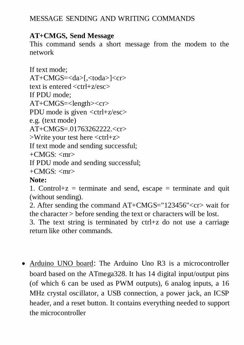
Vehicle Tracking System Aim of this project is to track the location of our Vehicle. This project gives Minute-by-minute updates about vehicle location by sending SMS through GSM modem. This SMS contains longitude and latitude of the location of vehicle. Microcontroller gets the coordinates from GPS modem and then it sends this information to the user in Text SMS. GSM modem is used to send this information via SMS. SMS will be sent to the owner of the vehicle. Block diagram Vehicle Tracking System
Transcript
Vehicle Tracking System
Aim of this project is to track the location of our Vehicle. This project
gives Minute-by-minute updates about vehicle location by sending SMS
through GSM modem. This SMS contains longitude and latitude of the
location of vehicle. Microcontroller gets the coordinates from GPS
modem and then it sends this information to the user in Text SMS. GSM
modem is used to send this information via SMS. SMS will be sent to
the owner of the vehicle.
Block diagram
Vehicle Tracking System
This project consists of following blocks:
1. GPS Modem
2. GSM Modem
3. Microcontroller (Arduino UNO)
4. LCD display
5. Power Adopter
GPS Modem: A GPS navigation device is a device that accurately
calculates geographical location by receiving information from
GPS satellites. GPS modems need to be connected to a computer in
order to work. This computer can be a home computer, laptop,
PDA, digital camera, or smart phones. Depending on the type of
computer and available connectors, connections can be made
through a serial or USB cable.
GPS receiver communication is defined within NMEA
specification. Most computer programs that provide real time
position information understand and expect data to be in this
standard.
Each sentence begins with a '$' and ends with a carriage return/line
feed sequence and can be no longer than 80 characters of visible
text. The data is contained within this single line with data items
separated by commas. The data itself is just ASCII text and may
extend over multiple sentences in certain specialized instances but
is normally fully contained in one variable length sentence.
Software serial multple serial test Receives from the hardware serial, sends to software serial.
Receives from software serial, sends to hardware serial.
The circuit: * RX is digital pin 10 (connect to TX of other device) * TX is digital pin 11 (connect to RX of other device)
Note:
Not all pins on the Mega and Mega 2560 support change interrupts, so only the following can be used for RX: 10, 11, 12, 13, 50, 51, 52, 53, 62, 63, 64, 65, 66, 67, 68, 69
Not all pins on the Leonardo support change interrupts,
so only the following can be used for RX: 8, 9, 10, 11, 14 (MISO), 15 (SCK), 16 (MOSI).
created back in the mists of time modified 25 May 2012
by Tom Igoe based on Mikal Hart's example
This example code is in the public domain.
*/ #include <SoftwareSerial.h>
SoftwareSerial mySerial(10, 11); // RX, TX
void setup() { // Open serial communications and wait for port to open:
Serial.begin(57600); while (!Serial) {
; // wait for serial port to connect. Needed for Leonardo only }
Serial.println("Goodnight moon!");
// set the data rate for the SoftwareSerial port mySerial.begin(4800);
mySerial.println("Hello, world?"); }
void loop() // run over and over {
if (mySerial.available()) Serial.write(mySerial.read());
if (Serial.available())
mySerial.write(Serial.read()); }
Programming Digital I/O pins of Arduino UNO board:
Each pin is controlled by three commands associated with it which are
designated as:
pinMode()
digitalWrite()
digitalRead()
pinMode()
This configures the specified pin to behave either as an input or an output.
Syntax
pinMode(pin, mode)
Parameters
pin: the number of the pin whose mode you wish to set
mode: INPUT, OUTPUT.
Returns
None
Example
int ledPin = 13; // LED connected to digital pin 13
void setup()
{
pinMode(ledPin, OUTPUT); // sets the digital pin as output
}
void loop()
{
digitalWrite(ledPin, HIGH); // sets the LED on
delay(1000); // waits for a second
digitalWrite(ledPin, LOW); // sets the LED off
delay(1000); // waits for a second
}
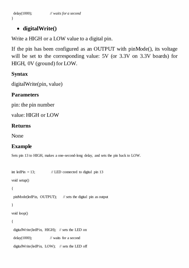
digitalWrite()
Write a HIGH or a LOW value to a digital pin.
If the pin has been configured as an OUTPUT with pinMode(), its voltage
will be set to the corresponding value: 5V (or 3.3V on 3.3V boards) for
HIGH, 0V (ground) for LOW.
Syntax
digitalWrite(pin, value)
Parameters
pin: the pin number
value: HIGH or LOW
Returns
None
Example
Sets pin 13 to HIGH, makes a one-second-long delay, and sets the pin back to LOW.
int ledPin = 13; // LED connected to digital pin 13
void setup()
{
pinMode(ledPin, OUTPUT); // sets the digital pin as output
}
void loop()
{
digitalWrite(ledPin, HIGH); // sets the LED on
delay(1000); // waits for a second
digitalWrite(ledPin, LOW); // sets the LED off
delay(1000); // waits for a second
}
digitalRead()
Reads the value from a specified digital pin, either HIGH or LOW.
Syntax
digitalRead(pin)
Parameters
pin: the number of the digital pin you want to read (int)
Returns
HIGH or LOW
Example
int ledPin = 13; // LED connected to digital pin 13
int inPin = 7; // pushbutton connected to digital pin 7
int val = 0; // variable to store the read value
void setup()
{
pinMode(ledPin, OUTPUT); // sets the digital pin 13 as output
pinMode(inPin, INPUT); // sets the digital pin 7 as input
}
void loop()
{
val = digitalRead(inPin); // read the input pin
digitalWrite(ledPin, val); // sets the LED to the button's value