Abstract. We describe here a new method to increase the peak current of high brightnesselectron beams as those required to drive X-ray SASE FEL's, that is based on a rectilinearcompressor scheme utilizing the bunching properties of slow waves. It is shown that whenever abeam, slower than the synchronous velocity, is injected into a RF wave at the zero accelerationphase and slips back in phase up to the peak acceleration phase, it can be compressed as far asthe extraction happens at the synchronous velocity. In fact, the bunch undergoes a quarter ofsynchrotron oscillation that induces a net compression (i.e. a bunch length reduction) up to afactor of 20 when proper care is taken to preserve the longitudinal emittance. A few examplesare presented to demonstrate the potentialities of this method, by which multi-kA beams at verylow emittance can be generated at moderate energies (about 100 MeV).
INTRODUCTION
The need to produce high brightness electron beams delivered in short (subpicosecond) bunches has been driven recently by the demands of X-ray SASE FEL's,which typically require multi-GeV beams with multi-kA peak currents and bunchlengths in the 100-300 fs range, associated to normalized transverse emittances lowerthan a few mm mrad.
The foreseen strategy to attain those beams is based in present designs on the use ofRF Linacs in conjunction with RF laser driven Photoinjectors and magneticcompressors. The formers are needed as sources of low emittance high charge beams(usually 2 mm mrad at 1 nC bunch charge) with moderate currents (< 100A@ 10MeV), the latter are used to enhance the peak current of such beams up to the designvalue of 2-3 kA by reduction of the bunch length achieved at relativistic energies (>300 MeV, up to 5 GeV in multi-staged compressors).
Since the impact of magnetic compressors on the beam dynamics is quite relevant,with tendency to jeopardize the performances of the whole system in terms of the finalbeam brightness achieved - this makes these type of compressors one of the criticalcomponents of these Linacs - we tried to explore an alternative option of compression(i.e. of current enhancement) based on slow wave RF fields.
The performances of this option are presented in this paper on the basis of apreliminary analysis, whose main conclusion is that this method of compression hasvery promising potentialities and is a good candidate to substitute magneticcompressors, alleviating in this way the problems related to Coherent SynchrotronRadiation emission occurring in the chicanes of magnetic compressors and its criticalimpact on the beam quality (brightness) achievable.
Downloaded 28 Dec 2003 to 128.97.23.18. Redistribution subject to AIP license or copyright, see http://proceedings.aip.org/proceedings/cpcr.jsp
The great advantage of the RF rectilinear compressor scheme presented here isobviously the absence of curved path trajectories in the compressor, in addition to thefact that compression is applied at moderate energies (from 10 to 100 MeV), leavingthe Linac (up to the final energy) free from any further beam manipulation needed toincrease the current.
The rectilinear RF compressor works indeed as a standard accelerating structurewhich, while accelerates the beam, it also reduces its bunch length.
We have to acknowledge here that the seed of the idea leading to the RFcompressor was set in the development of a previous work on a plasma buncherscheme[l] which turned out to be of great relevance for the studies on secondgeneration plasma accelerators[2].
In that work indeed it was shown that a plasma accelerator working at someresonant gamma jr can accelerate and simultaneously compress long bunches injectedat a proper phase, i.e. the phase of no net acceleration. In that specific example, aplasma wave driven at an amplitude of 3 GV/m with plasma wavelength of 300 |o,maccelerates an electron bunch injected at 2.5 MeV up to an energy of 200 MeV, bysimultaneously reducing the bunch length from 15 |im at injection down to 3 |im . Inorder to achieve this effect is necessary to inject at 0° phase (no acceleration) so to letthe beam slip back in phase and extract the beam when its energy is close to theresonant gamma of the wave (in this case 7 = 400 ). In case of injection at 90° (maxacceleration) the bunch would be accelerated up to a higher final energy (290 MeV)but its length would be left unchanged.
The longitudinal component Ez of the RF field in a traveling wave structure or aLangmuir wave in a cold plasma can be well approximated by a simple expressionneglecting higher order spatial harmonics
E= -E0sm(cM - kz + Vo) (1)
where the wave number k is taken to be k = —— (implying a wave phase velocityPrc
given by vr = /?rc , jr = 1/̂ /1 - /Jr2 ) and the wave amplitude EQ can be cast in terms
eEof a dimensionless parameter a , defined as a = —f-, which represents theme k
normalized amplitude of the vector potential associated to the wave electric field (weare considering here waves with phase velocity quite close to c, or, in other words,resonant gamma's quite large, jr »1 ).
The interaction between an electron and a wave of this kind can be described by anHamiltonian
# = 7-j3rA/72-l-acos£ (2)
Twhere 7 is the normalized energy of the electron, 7 = 1 + —- and ^ = kz-0)t-\i/0mee hase of the wave as seen b the electron.the phase of the wave as seen by the electron.
Downloaded 28 Dec 2003 to 128.97.23.18. Redistribution subject to AIP license or copyright, see http://proceedings.aip.org/proceedings/cpcr.jsp
Let us consider now a wave whose phase velocity is slightly smaller than c, so thatk = kQ+Ak = — + A& , and the detuning parameter A& is small, i.e. Ak«kQ ; the
cresonant beta and gamma can be well approximated by
coand (3)
soIn previous example related to the plasma wave accelerator we have 7 = 400the detuning parameter is AA: = 3.1 • W~6kQ .
The trapping and acceleration in these waves has been widely discussed in theliterature (see for example in ref.3), and it can be well understood looking at the phasecontour plots in the [y,£] phase space. One of the most relevant feature is thatwhenever the resonant gamma is finite, i.e. the wave is slower than c, we have aseparatrix in this space, splitting trapped orbits from untrapped ones.
[rad]
FIGURE 1. Phase space plots for a slow wave with resonant gamma J = 12 and CC — 0.2separatrix is shown by the bolded line.
The
This situation is illustrated in Fig. 1 for the case of a wave of amplitude a - 0.2 andresonant gamma 7 = 12 . This corresponds to a wave phase velocity of /?r = 0.9965 oran equivalent detuning parameter of Ak = 3.5-10~3&0 . The top of the separatrix (i.e.
89
Downloaded 28 Dec 2003 to 128.97.23.18. Redistribution subject to AIP license or copyright, see http://proceedings.aip.org/proceedings/cpcr.jsp
the value of 7 at £ = 0 for 70=7 r and \i/0=n) is approximately given by7max = 4^7;* , which is the maximum energy of trapped particles .
Since the Hamiltonian written in eq.2 is an invariant of the motion, we can evaluateit at injection, getting:
= 7o - (4)
where 70 and I/SQ are the initial energy and phase of the particle injected into thewave. The maximum accelerating gradient occurs at £ = -;r/2 : if particles areinjected at this phase inside the separatrix region with an initial energy 70 smaller thanthe resonant one jr they will slip back in phase but they will be accelerated up toy = 7r , where their velocity will match that of the wave, thereafter they will start toslip ahead of the wave during the acceleration up to the highest 7 value of their phasecontour line (well above /r) corresponding to £ = 0. At this point they will start beingdecelerated unless extracted from the wave.
There is one relevant property of this kind of energy oscillation performed into thebucket by trapped electrons, which turns out to be very helpful in reducing the phasedistance of particles injected close to each other into the wave at small energy.
FIGURE 2. Enlarged part of the diagram plotted in Fig. 1, corresponding to 7 < 20 .
90
Downloaded 28 Dec 2003 to 128.97.23.18. Redistribution subject to AIP license or copyright, see http://proceedings.aip.org/proceedings/cpcr.jsp
Because of the shape of the phase contour lines, the region around £ = 0corresponds to high phase spreads and low energy spreads while the opposite is truefor the region around % = -n!2 where the phase lines are parallel to the /-axis.
This is quite well illustrated in Fig.2 where an enlarged part of the diagram plottedin Fig. 1 is shown, and exactly that corresponding to 7 < 20 . In this figure a particledistribution at injection is depicted in a small phase space area located around £ = 0and 70 = 3 , i.e. well below yr (i.e. particles initially slower than the wave) and closeto the bottom of the cup-shaped bucket. This bunch of particles is accelerated by thewave while it slips back in phase: once at the resonant energy yr it will reach a phaseof about % = -60°. As depicted in the diagram, due to the nature of the phase lines, thebunch will have a phase spread (i.e. a bunch length since it is quite relativistic at thispoint) smaller than the initial one, which means that this kind of acceleration acts alsoas a phase compression.
Extracting the bunch when it reaches jr is therefore the way to achieve a bunchlength compression at the same time as acceleration: a further acceleration beyond jrwould clearly tend to de-compress the bunch, as clearly shown by the shape of thephase lines above jr (inside the separatrix).
We can evaluate the amount of phase compression achieved by assuming injectionat £ = 0 and extraction at 7 = y r , so that eq.4 becomes
Y r
which basically determines the extraction phase ^ as a function of the injectionconditions (7o,Vo) and the wave parameters (yr,tf) .
We also assume that the injection phase \l/0 and energy 70 will be distributedaround some average values 70 and \J7Q with rms spreads defined as 70 = f 0 ± SYO and\I/Q - \J70 ±Si//0 . These initial spreads in energy and phase at injection will affect thefinal phase spread 8%^ at extraction as given by
±570)2 -1 +acos(±5vA0) , which can becast, through a second order expansion, in the form
— 1 y / _ \where the extraction phase is specified by cos ̂ = 1 + —— -—(1 - /Jr/30) .ajr a ^ 'The relevant parameter is the compression factor C, sort of a figure of merit for
this process, defined as the ratio between the initial phase spread and the final one atextraction, i.e. C = —|— , which turns out to be given by
91
Downloaded 28 Dec 2003 to 128.97.23.18. Redistribution subject to AIP license or copyright, see http://proceedings.aip.org/proceedings/cpcr.jsp
C- (7)
fwhere we assumed -̂ - « 1 .fr
Taking the example shown in Fig.2, i.e. a bunch injected at 7 0=3 with-^- = 5 • 10~3 and S\i/Q - 5 - 10~2 into a wave specified by a = 0.2 and jr = 12 , we7o _
derive from eq.7 a compression factor C = 9. 8 , at an extraction phase ^ =-60° ,which indicates a quite interesting capability to increase the peak current in the bunchby a relevant factor (in excess of 10).
Taking as a second example the one considered in the work on plasma bunchers,_ Syi.e. a bunch injected at f0 = 6 with -4r~ - 5 • 10~3 and S\i/0 = 0.31 (a bunch 15 u,m
7olong into a plasma wave with 300 jam wavelength) into a wave specified by a - 0.28 (3GV/m amplitude) and jr - 400 , we derive from eq.7 a compression factor C = 4.5 ,at an extraction phase ̂ = -45° , which is very close to the factor 5 in bunch lengthreduction observed in the numerical simulations, that foresee a final bunch length of 3|im at the exit of the plasma wave[l] .
RF RECTILINEAR COMPRESSORS
On the basis of the bunch compression mechanism described above we canenvisage a very useful application of this concept in the frame of high brightnessphotoinjectors for X-ray PEL drivers.
The aim of the idea is to try compressing the beam right after the exit from the RFgun, when the energy is about 5-7 MeV, by injecting the bunch into an acceleratingstructure which supports a slow wave like the one specified in eq.l, so that the beamwould leave this structure at the final maximum value of peak current achievable at anenergy close to (or somewhat higher) than the resonant gamma. If this exit energy ishigh enough we can envisage that the residual longitudinal space charge field will notdebunch the beam further on, in particular if the beam is promptly injected into aregular high gradient accelerating structure in order to relativistically freeze down theresidual - generally weak - longitudinal space charge forces.
We will consider here the lay-out of the injector for the LCLS[4], which is one ofthe most promising designs for high brightness beams recently proposed[5], based onthe use of S-band traveling wave structures boosting a 6.5 MeV beam produced by theRF gun. The paradigm for this beam is: 1 nC bunch charge, 10 ps laser pulse length onthe photocathode, 140 MV/m peak field on the photocathode, resulting in a 100 A
92
Downloaded 28 Dec 2003 to 128.97.23.18. Redistribution subject to AIP license or copyright, see http://proceedings.aip.org/proceedings/cpcr.jsp
peak current at the gun exit with 0.8 % energy spread and 0.5 mmmrad rmsnormalized transverse emittance (as predicted by simulations). A solenoid lens locatedright at the gun exit focuses down the beam in order to match its envelope onto theinvariant envelope[7] at the injection in the first TW structure, which is located 1.5 mfar from the cathode[5]. We just take this lay-out and substitute the first TW structurewith one that is properly designed to support a slow wave with wave number 0.07 %higher than the nominal one (corresponding to a cell length 0.07 % shorter than thestandard A/3 nominal value of a 2n/3 mode - this perturbative change in wavenumber is equivalent to a 2 MHz detuning of the structure, i.e. to having a 2854 MHzfield propagating through a standard S-band SLAC structure). This structure will have86 cells over a length of about 3 m, operating at 2856 MHz.
150
125
gamma-r
gamma-0
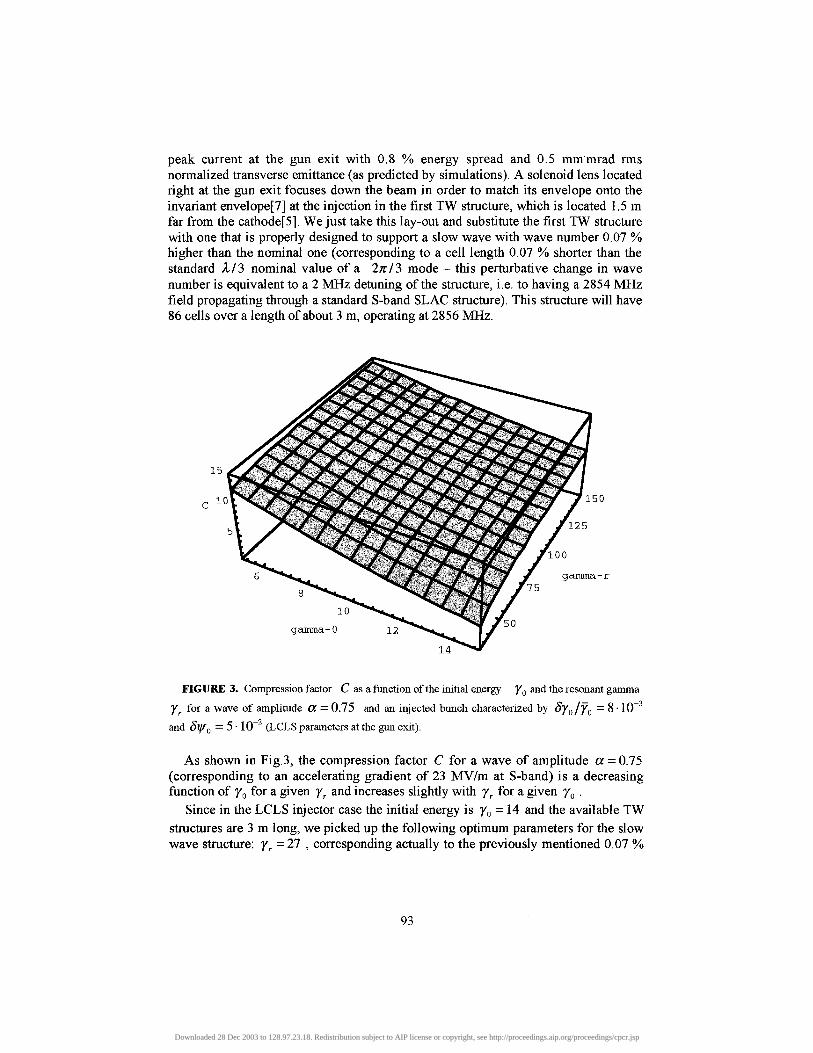
FIGURE 3. Compression factor C as a function of the initial energy yo and the resonant gamma
Yr for a wave of amplitude CC = 0.75 and an injected bunch characterized by 570/70 = 8 • 10~and SI/SQ =5-10" (LCLS parameters at the gun exit).
As shown in Fig.3, the compression factor C for a wave of amplitude a = 0.75(corresponding to an accelerating gradient of 23 MV/m at S-band) is a decreasingfunction of y0 for a given jr and increases slightly with yr for a given y0 .
Since in the LCLS injector case the initial energy is y0 = 14 and the available TWstructures are 3 m long, we picked up the following optimum parameters for the slowwave structure: yr = 27 , corresponding actually to the previously mentioned 0.07 %
93
Downloaded 28 Dec 2003 to 128.97.23.18. Redistribution subject to AIP license or copyright, see http://proceedings.aip.org/proceedings/cpcr.jsp
increase in wave number and a = 0.75 . For this set of parameters the predictedcompression factor is C - 6.5 .
By optimizing the injection phase, we ran Homdyn [6] from the cathode surface allthe way through the gun, drift, slow wave structure, up to the exit of a second 3 m longTW structure (regular one, no detuning, driven at 27 MV/m accelerating gradient),located right after the first detuned one. At the optimum phase (slightly earlier than 0°)we found a very nice final peak current of 870 A at an energy of 120 MeV, as shownin Fig.4.
The effect of the RF rectilinear compressor (the detuned structure), extending fromz=1.5 m up to z=4.5 m, is clearly illustrated: the energy at its exit is 18.5 MeV(y = 37? somewhat larger than jr ) and the compression takes place almost entirelyduring the acceleration through it. The compression factor achieved is C- 8.1 , a bitlarger than the analytical prediction[10].
1000
800
600 -
250
- 200
- 150
400 -
200 -
- 100 —
10Z[m]
FIGURE 4. Beam current (solid line, left scale, in A) and energy evolution (dashed line, right scale,in MeV) through the LCLS injector with implementation of a RF rectilinear compressor.
The energy spread is plotted in Fig.5: after a large peak due to the injection at 0°phase, where the dominant effect is to induce energy spread instead of accelerating thebunch, it is naturally damped by acceleration, reaching about 1% at the exit.
The transverse dynamics is strongly altered by the compressor because the beam isall the way space charge dominated in the transverse plane: the plasma oscillationshown by the beam envelope in Fig.5 must be carefully taken under control by thesolenoids wrapped around the two accelerating sections (by proper tuning of their fieldamplitude) so to achieve an emittance correction scheme[7] that extends through thetwo accelerating structures up to 120 MeV. The final value reached, 0.5 mm mrad, is
94
Downloaded 28 Dec 2003 to 128.97.23.18. Redistribution subject to AIP license or copyright, see http://proceedings.aip.org/proceedings/cpcr.jsp
consistent with the design value reported for the LCLS injector study, showing that theoptimal emittance correction can be achieved even in presence of the RF compressor.
The rms longitudinal emittance (not shown in the figures) goes from 25 keV mm atthe exit of the RF gun up to 155 keVmm at the exit of the RF compressor: we believethat this is due to the non-linear behavior of the accelerating field versus theaccelerating phase that introduces a curvature in the longitudinal phase space. Thecontribution of the longitudinal space charge forces is indeed negligible throughout theRF compressor: in fact, repeating the simulation shown in Fig. 4-5 by switching offthe space charge at the injection into the compressor we have obtained results almostidentical to the previous case (actually the final value of the peak current is slightlysmaller - 860 A - for the zero space charge case, as for the longitudinal emittance).
j=A
DCV
z[m]
FIGURE 5. Energy spread in % (dotted line, right scale), beam envelope in mm (solid line, leftscale) and rms normalized transverse emittance in mmmrad (dashed line, left scale) evolution as forFig.4.
Therefore, if the maximum peak current achievable is limited by RF non-linearitiesthere should be two ways to overcome this problem: one is the decrease in theaccelerating gradient the second is the use of higher harmonics to flatten-out theenergy-phase correlation [8].
We will discuss the second option in the next section of this paper: let us nowconsider what is the behavior of the compression factor C as a function of cc (i.e. theaccelerating gradient). This is plotted in Fig.6, clearly displaying that there is actuallyan optimum value of a - about 0.25 - that maximizes the compression factor.
We repeated the simulations with the same injected beam and same slow wavestructure as before, but changing now the gradient, i.e. applying 13 MV/m,corresponding to a = 0.44, and increasing the structure length up to 6 m. The resultsare plotted in Fig.7: at an exit energy of 24 MeV the beam peak current is 1260 A with
95
Downloaded 28 Dec 2003 to 128.97.23.18. Redistribution subject to AIP license or copyright, see http://proceedings.aip.org/proceedings/cpcr.jsp
a longitudinal emittance of 80 keVmm. As anticipated, at lower gradients thelongitudinal emittance is better due to lower non-linear RF effects, hence themaximum peak current achievable is considerably higher.
10
0.5 1
alfa
1.5
FIGURE 6. Compression factor C plotted as a function of CC for the same beam conditions atinjection and slow wave structure used in Fig.4-5.
1400
1200
1000
800
600
400
200
0
350
300
250
200 H
150 <
100
50
010Z[m]
15 20
FIGURE 7. Beam current (solid line) and energy evolution (dashed line, right scale) through theLCLS injector with implementation of a 6 m long RF compressor driven at low accelerating gradient.
96
Downloaded 28 Dec 2003 to 128.97.23.18. Redistribution subject to AIP license or copyright, see http://proceedings.aip.org/proceedings/cpcr.jsp
The impact of these RF non-linear effects is clearly shown by the behavior of thelongitudinal phase space distributions plotted in Fig.8 at various locations through thecompressor.
I
14
?R
L """
2 -1.5 -1 -0.5 CDZ
. ... j .... j . . . . . . . . .
.................... .p̂
2 -1.5 -1 -0.5 CDZ
%
;
0.5 1 1.5 2[mm]
0.5 1 1.5 2:mm]
\ I
44
'"* —— --^
2 -1.5 -1 -0.5 CDZ
i....... ........ .......JS^
. . . . i . . . . . . . . . . . .2 -1.5 -1 -0.5 C
DZ
1
: : : : : : : : >= ..................... i
0mm]
^
) 0[mm]
"*"""•«» . «
.5 1 1.5 2
5 1 1 . 5 2
-2 -1.5 -1 -0.5 0 0.5 1 1.5 2DZ_[mm]
-2 -1.5 -1 -0.5 0 0.5 1DZ [mm]
FIGURE 8. Beam phase space distributions in the (Az, pz J longitudinal plane at different locationsthrough the 6 m long RF compressor (these are snapshots taken in time, as the code Homdyn is time-dependent). First diagram is for the beam at injection, last diagram is for the beam right at thecompressor exit.
The first diagram shows the energy phase distribution of the beam at injection intothe compressor with a clear signature of the longitudinal space charge field actionoccurred from the photocathode surface up to the exit of the gun and further onthrough the drift to the compressor: some non-linearities are already present butmostly concentrated in the bunch tails, as expected. The second diagram is taken afterthe bunch has traveled a few wavelengths: since the injection is performed at 0° , mostof the RF field action goes into producing an almost linearly correlated energy spreadwith particles in the tail being at higher energy than those in the bunch head. Aftersome more RF periods - third diagram - the bunch starts being accelerated because ofthe phase slippage to higher phases - the beam is indeed slower than the wave at thispoint. At the same time the beam starts being bunched because of the phase space
97
Downloaded 28 Dec 2003 to 128.97.23.18. Redistribution subject to AIP license or copyright, see http://proceedings.aip.org/proceedings/cpcr.jsp
rotation caused by the linearly correlated energy spread. These two actions - bunchingand acceleration - proceed actually together in a synergic way (see fourth and fifthdiagrams) until an almost full rotation is achieved. The bunching couldn't be achievedat these moderate energies unless the average beam energy wouldn't be raised byacceleration to damp the outward pressure of the longitudinal space charge forces, butunfortunately the acceleration process induces a phase space curvature that in turnsincreases the longitudinal emittance and prevents reaching much shorter bunchlengths. If the process is pushed up to its limit the beam reaches the exit of thecompressor (sixth diagram, average energy 24 MeV) being over-compressed. Thismeans that the energy spread is now no longer correlated and it could not be correctedby a further acceleration off-crest to higher energies - as is typically done in Linacswith magnetic compressors. We will show however in the next section an example ofpartial compression with further energy spread correction, that is possible by justadjusting the injection phase into the compressor.
As discussed, the crucial feature of this method is the use of a slow RF structuresuch that the beam can be injected at a speed slower than that of the wave but it leavesthe structure, after acceleration, being faster than the wave itself, i.e. at energies largerthan the resonant gamma. The phase slippage is quite large during the compression,even up to 50-60° RF.
It would be possible to achieve such a phase slippage even in standard TWstructures which are non-detuned, i.e. those having a wave phase velocity equal to thespeed of light, for which the resonant gamma is actually infinity. In this structures thebeam would be always slower than the wave, so that it would not be possible not evento reach the resonant gamma by the end of the RF compressor.
We anyway checked the potentialities of RF compressors based on non-detunedstructures just by running Homdyn on the LCLS injector scheme and using lowinjection phases in the first TW structure (i.e. we repeated the simulations presented inFig.4-5 just by setting Ak = 0 ). The maximum peak current achievable is in this case250 A at 28 MeV exit energy from the compressor, with a longitudinal emittance of150keVmm.
RF RECTILINEAR COMPRESSORS WITH HIGHERHARMONIC CORRECTORS
Since the main limitation to the performances of the RF compressor basicallycomes from the RF nonlinearities, a possible solution to this is the use of higherharmonics superimposed to the main RF field, aimed at correcting locally the RFcurvature and avoid the huge increase of longitudinal emittance which is, in turn,responsible of the limitation in the minimum bunch length achievable.
The superposition of higher harmonics is indeed not conceivable inside the sameslow wave structure of the compressor: it couldn't even be placed after thecompression if this is pushed up to the overcompression limit (as shown in Fig.8),hence it's natural to conceive a lay-out in which the higher harmonic structure isplaced before the compressor, i.e. in the drift between the gun and the compressor
Downloaded 28 Dec 2003 to 128.97.23.18. Redistribution subject to AIP license or copyright, see http://proceedings.aip.org/proceedings/cpcr.jsp
itself. This drift (about 1 m long) is needed to accomplish the first part of thetransverse emittance correction by properly focusing the beam plasma oscillationsthrough it.
We therefore consider here a lay-out as shown in Fig.9, with a short (7 cell) thirdharmonic structure placed right before the RF compressor, which is now followed by 5standard 3 m long S-band SLAC TW structures in order to raise the beam energy up to500 MeV, where the transverse space charge effects are expected to be negligible evenfor a 2 kA beam from the point of view of the emittance correction budget.
L. RF RectilinearCompressor
Ill Harmoniccavity
SLAC Structures
FIGURE 9. Layout of a 500 MeV Linac based on a RF compressor with 3rd harmonic correction for thegeneration of a 2.3 kA beam with no use of magnetic compressors.
The RF compressor is set at same conditions as in the previous example, i.e.yr = 27 ( A& = 0.07%), driven at 23 MV/m accelerating gradient, while the followingstructures are driven at 27 MV/m (but the first one, set at 31 MV/m).
The 3rd harmonic structure, being 8.2 cm long, is driven at 40 MV/m at a frequencyof 8568 MHz (no detuning). Its role is indeed to pre-correct the RF induced curvaturein the longitudinal phase space distribution as that shown in Fig. 8: in order to achievethis task is actually enough that the total energy decrease induced by the 3rd harmonicstructure is close to 1/9 of the total energy increase produced by acceleration into theRF compressor. This would in fact correct at least the second order derivative (scalinglike n2 , n being the harmonic number) of the phase space curvature, with a significantbenefit to the longitudinal emittance.
This rule of the thumb would set a 3rd harmonic total energy decrease at 2.6 MeV,just one ninth of the total energy gain in the compressor, i.e. 23.5 MeV. From thesimulations we found instead that the best results are obtained for an energy decreaseof about 3.5 MeV, that corresponds to 40 MV/m ace. gradient. The reason for this
99
Downloaded 28 Dec 2003 to 128.97.23.18. Redistribution subject to AIP license or copyright, see http://proceedings.aip.org/proceedings/cpcr.jsp
disagreement is that the beam enters the compressor at 3 MeV, hence the energy gainand phase slippage are higher than before - as for the compression factor.
We should also notice that the exit energy from the compressor is in this casehigher (30 MeV) than the case presented in previous section (see Fig.4): the reason isthe higher phase slippage toward the RF field crest due to a lower injection energy inthe compressor (3 MeV instead of 6.5 MeV).
Eventually the performances of the system are dramatically improved, thanks to thelongitudinal emittance correction performed by the 3rd harmonic field, which brings itdown to 25 keVmm at the exit of the compressor, as opposed to 155 keVmm withoutthe 3rd harmonic correction. The beam current and energy throughout the Linac areplotted in Fig. 10, while the energy spread and longitudinal emittance in Fig. 11.
2500
2000
1500
1000
500
500
400
300
200
100
1 0 1 5 20 25
z[m]
FIGURE 10. Beam current (solid line, left scale, in A) and energy evolution (dashed line, rightscale, in MeV) through a 500 MeV Linac with implementation of a RF rectilinear compressor and a 3rd
harmonic corrector.
The final peak current value is 2.3 kA at full compression, with an energy spread of0.13 % at the end of the Linac, and a normalized rms transverse emittance still at 0.6mmmrad. It's interesting noticing the longitudinal emittance correction mechanismdeveloped by the 3rd harmonic structure, located at 1.2 m from the photo-cathode: itactually blows up the longitudinal emittance from 15 to 37 keVmm, as plotted inFig. 11, because of the positive curvature induced to the longitudinal phase spacedistribution, which is however corrected further on by the negative curvature
100
Downloaded 28 Dec 2003 to 128.97.23.18. Redistribution subject to AIP license or copyright, see http://proceedings.aip.org/proceedings/cpcr.jsp
contribution produced by the main RF field in the compressor. This brings eventuallyback the longitudinal emittance to its final value of 24 keV mm, which allows for acompression factor almost 3 times larger than that obtained in absence of the 3rd
harmonic corrector (see Fig.4).
25
1 5
(
; '
'
I)
\
^
i
\i
i
^
, , , ,
5 1
x^
~-
1 1 1 1
0 1
, , , ,
— — - - _ _ _
, , . .
5 2
i i i i
0 2
0.5
5
z[m]
FIGURE 11. . Energy spread in % (dotted line, right scale) and longitudinal emittance in keV mm(solid line, left scale) evolution as for Fig. 10 .
1 0
- . , . .1 -0
1 I .1 J 1 • 1 i ••7";-r — —»»~"-;»»-̂ ;""~"»—
""? '*«£
'"*•£:•..;..;;̂ .̂'...'. .
. . , . i . , , .. 5 0 0
DZ [mm]
-, , , . -
.5 1
FIGURE 12.. Longitudinal phase space distributions taken at different times throughout thecompressor for the case of total compression.
101
Downloaded 28 Dec 2003 to 128.97.23.18. Redistribution subject to AIP license or copyright, see http://proceedings.aip.org/proceedings/cpcr.jsp
The compression is pushed in this case up to its maximum limit, as shown inFig. 12, where the phase space distributions are plotted at various times throughout thecompressor. The residual energy spread is totally uncorrelated to the phase, hence notrecoverable any longer.
If the compression is performed partially so that a linear correlation is still presentat the exit of the compressor between the energy and phase of particles in the bunch,this correlated energy spread can be corrected by running the beam slightly off-crest inthe following accelerating sections: as an example, it is possible to produce a beamwith peak current of 600 A and a final energy spread (at the Linac exit, 500 MeV) of0.04 % . The evolution along the Linac of the corresponding phase space distributionsis reported in Fig. 13
O)*N0>
FIGURE 13.. Longitudinal phase space distributions taken at different times throughout the Linac forthe case of partial compression.
The transverse dynamics is shown in Fig. 14, where the rms beam envelope andnormalized emittance are plotted along the Linac: the final emittance is still close to0.55 mmmrad, and this is again achieved by a careful setting of the field amplitudesand the locations of many solenoids placed around the RF compressor and thefollowing two accelerating sections in order to keep focused the beam despite itsincreasing peak current. To this purpose, the RF compressor had to be placed closer tothe RF gun exit, i.e. at 1.4 m far from the photocathode instead of 1.5 as for the LCLSnominal layout. Details of the transverse dynamics in this region are plotted in thelower diagram of Fig. 14. No real systematic analysis has been done to optimize the
102
Downloaded 28 Dec 2003 to 128.97.23.18. Redistribution subject to AIP license or copyright, see http://proceedings.aip.org/proceedings/cpcr.jsp
transverse emittance up to 500 MeV: adding more solenoids in the last twoaccelerating sections would definitely help in taking the beam envelope better undercontrol and getting a better emittance at the Linac exit.
2.5 2500
- 1500
2.5 2500
^ 1500
FIGURE 14. Rms beam envelope in mm (dotted line, left scale), rms normalized transverseemittance in mm mrad (solid line, right scale) and beam peak current in A (solid line, right scale) alongthe Linac. The lower diagram shows the details of the upper one along the first 3 m of RF gun, drift, 3rd
harmonic structure (from z=1.2 to z=1.28) and RF compressor (from z=l .4 to z=4.4)
103
Downloaded 28 Dec 2003 to 128.97.23.18. Redistribution subject to AIP license or copyright, see http://proceedings.aip.org/proceedings/cpcr.jsp
RF RECTILINEAR COMPRESSORS WITH STANDING WAVESTRUCTURES
The analysis performed so far has been focused on the use of traveling wavestructures, where the analytical treatment reported in the introduction strictly applies.
There is however a relevant interest also in applying this concept in the domain ofLinacs based on standing wave structures. For this case an analytical theory of therectilinear compressor has not yet been investigated in details. Nevertheless we expectto apply the previous treatment provided that only the forward travelling wavecomponent of the standing wave is considered.
500
400 -
300 -
200 -
100 -
250
- 200
- 150
- 100
15 20 25Z_[m]
FIGURE 15. Beam current (solid line, left scale) and energy evolution (dashed line, right scale)through the TESLA-FEL injector with implementation of a 11 m long RF compressor (firstcryomodule).
We have applied for demonstration the rectilinear compressor concept to an injectorbeam line based on superconducting standing wave structures, as the one designed forthe TESLA FEL project [9]. We have considered in this case a 1.3 GHz if gun, 1.5cells long, followed by two cryomodules each one containing 8, 1.3 GHz, 9 cellsstanding wave structures. A InC bunch is extracted from the cathode by a 20 ps longlaser pulse in a 60 MV/m if peak field and accelerated up to 6.6 MeV (yo=14) at thegun exit, resulting in a 50 A peak current (with 0.7 % energy spread and 0.6 mm-mradrms transverse normalized emittance minimum). By detuning the first group of 8cavities so to increase the wave number by 0.08 % , corresponding to a resonant
104
Downloaded 28 Dec 2003 to 128.97.23.18. Redistribution subject to AIP license or copyright, see http://proceedings.aip.org/proceedings/cpcr.jsp
gamma yr=25.5, and operating the detuned structures at 50 MV/m peak field,corresponding to oc=1.8 for the forward travelling wave component, the expectedcompression factor results to be C=4.
The effectiveness of the rectilinear compressor scheme based on standing wavestructures is clearly visible in Fig. 15 where the energy gain and the peak current arereported up to the end of the second cryomodule. A compression ratio higher than 9has been obtained without any attempt to optimize the longitudinal and transverseemittances nor the energy spread of the beam.
We can definitely speculate, nevertheless, that even in SW Linacs it should bepossible to attain peak currents in excess of 1 kA by implementation of higherharmonic correctors as it was shown in previous section.
CONCLUSIONS
On the basis of the very preliminary analysis presented in this paper we mayconclude that the use of RF rectilinear compressor can be very helpful in the design ofSASE X-ray FEL drivers, either in alternative to magnetic compressors, or to alleviatethe criticality of these devices, i.e. in order to avoid multi-staged magneticcompressors that appear critical in those projects.
In fact, we have shown here that peak currents in excess of 2 kA are achievablewith the use of properly designed RF compressors. Since there is no systematic studyperformed so far on these devices we might speculate that one should be able to reacheven higher current levels (> 3 kA ?). In case one is aiming at higher currents the useof a magnetic compressor could be unavoidable, but its criticality should bediminished by the lower compression factor required to it - because the beam wouldalready have more than 1 kA of peak current at its entrance.
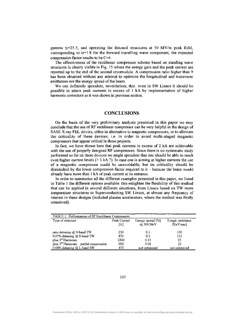
In order to summarize all the different examples presented in this paper, we listedin Table 1 the different options available: this enlighten the flexibility of this methodthat can be applied in several different situations, from Linacs based on TW roomtemperature structures to Superconducting SW Linacs, at almost any frequency ofinterest in these designs (included plasma accelerators, where the method was firstlyconceived).
TABLE 1. Performances of RF Rectilinear Compressors._________________________Type of structure Peak Current Energy spread [%] Longit. emittance
Downloaded 28 Dec 2003 to 128.97.23.18. Redistribution subject to AIP license or copyright, see http://proceedings.aip.org/proceedings/cpcr.jsp
ACKNOWLEDGMENTS
We acknowledge very helpful discussions with G.D'Auria and C.Rossi on slow-wave structures for the RF compressor.
REFERENCES1. M. Ferrario, T. C. Katsouleas, L. Serafini, I. Ben-Zvi.,"Adiabatic Plasma Buncher", in publication
on IEEE Trans. on Plasma Science, 28, no.4 (2000).2. C. Clayton and L. Serafini, IEEE Trans. on Plasma Science 24, p.400 (1996).3. C.S. Liu, V. K. Tripathi, Interaction of Electromagnetic Waves with Electron Beams and Plasmas ,
World Scientific Publ, 1994, pp. 60-63.4. J. Arthur et al., Linac Coherent Light Source (LCLS) Desing Study Report, SLAC-R-251, Apr. 1998.5. M. Ferrario, J. Clendenin, D. Palmer, J. Rosenzweig, L.Serafini,, "HOMDYN study for the LCLS
photoinjector", in publication on Proc. 1C FA Workshop on The Physics of High Brightness Beams,Ed. J. Rosenzweig and L. Serafini, World Scientific Publ., (2000).
6. M. Ferrario, A. Mosnier, L. Serafini, F. Tazzioli, J.M. Tessier, Particle Accelerators 52, p.l , (1996).7. L. Serafini and J. B. Rosenzweig, Physical Review E 55, p.7565 (1997).8. D. H. Dowell, T. D. Hayward, A. M. Vetter, IEEE Cat. no. 95CH35843, p.992 (1996).9. Conceptual Design of a 500 GeV e+e- Linear Collider with Integrated X-ray Laser Facility, Ed. R.
Brinkmann, G. Materlik, J. Rossbach, A. Wagner, DBSY-1997-048.10. The analytical model takes indeed into account only initial energy and phase spreads which are
uncorrelated and uniformly distributed around the average injection energy and phase. Thesimulations are instead done with injection conditions for the beam (see fig.8) that imply correlatedlongitudinal distributions with only partial fill-up of the longitudinal phase space: this may be thereason why the analytical model tend to underestimate the compression factor.
106
Downloaded 28 Dec 2003 to 128.97.23.18. Redistribution subject to AIP license or copyright, see http://proceedings.aip.org/proceedings/cpcr.jsp