Homewerks.com VENTILATION BATH FAN MODEL 7107-03HW Español p. 11 02-2021 Questions, problems, missing parts? Before returning to the store, call our customer service department at 1-877-319-3757, 7:30 a.m. - 4:30 p.m., CST, Monday - Friday. READ AND SAVE THESE INSTRUCTIONS
Transcript
Homewerks.com
VENTILATION BATH FAN
MODEL 7107-03HW
Español p. 11
02-2021
Questions, problems, missing parts? Before returning to the store, call our customer service department at 1-877-319-3757, 7:30 a.m. - 4:30 p.m., CST, Monday - Friday.
READ AND SAVE THESE INSTRUCTIONS
2 Homewerks.com
TABLE OF CONTENTS
UL Compliance ...................................................................................................................................................................2
Hardware Included .............................................................................................................................................................3
Safety Information ..............................................................................................................................................................4
Care and Cleaning..............................................................................................................................................................9
Ventilation Fan Motor Wheel Assembly B is combined into Ventilation Fan Motor Housing B-1 which is mounted into the ceiling opening. These components comply with UL File 507: section 10.6, section 62.2.3, section 62.4.1, and section 64A.9.
LIMITED 3-YEAR WARRANTYIf the fan fails due to a defect in materials or workmanship at any time during the first THREE years of ownership, the manufacturer will replace it free of charge, postage-paid at their option. This warranty does not cover products that have been abused, altered, damaged, misused, cut or worn. This warranty does not cover use in commercial applications. Use only manufacturer-supplied genuine warranty repair replacement parts to repair this fan. Use of non-genuine repair parts will void your warranty. The manufacturer DISCLAIMS all other implied or express warranties including all warranties of merchant-ability and/or fitness for a particular purpose. As some states do not allow exclusions or limitations on an implied warranty, the above exclusions and limitations may not apply. This warranty gives you specific legal rights, and you may have other rights that vary from state to state. This warranty is limited to the replacement of defective parts only. Labor charges and/or damage incurred during installation, repair, replacement as well as incidental and consequen-tial damages connected with the above are excluded. Any damage to this product as a result of neglect, misuse, accident, improper installation or use other than the purpose SHALL VOID THIS WARRANTY. Shipping costs for return product as part of a claim on the warranty must be paid for by the customer. Inquiries regarding warranty claims can be directed to 1-877-319-3757, 7:30 a.m. - 4:30 p.m., CST, Monday - Friday.
PRODUCT SPECIFICATIONS
Airflow: 110 CFM Sound output: 1.0 sone120V, 60Hz Motor power consumption: 30WDuct diameter: 4 in. Weight: 14.14 lbs.
3Homewerks.com
HARDWARE INCLUDED (not actual size)
AA BB CC
Wood Screw M4 x 30
Machine ScrewM4 x 12
Machine ScewM4 x 10
Qty. 8 Qty. 2 Qty. 1
PACKAGE CONTENTS
PART DESCRIPTION QTYA Fan Housing 1B Grille 1C Suspension Bracket 1
PART DESCRIPTION QTYD Suspension Bracket 1E Suspension Bracket 1
AC
D
E
B
4 Homewerks.com
SAFETY INFORMATIONPlease read and understand this entire manual before attempting to assemble, operate or install the product.
• Always disconnect the power supply prior to servicing the fan, motor or junction box.
• Follow all local building, safety and electrical codes as well as NEC (National Electrical Code) and OSHA (Occupational Safety and Health Act).
• Electric Service supply must be 120 volts, 60 hertz.• This product must properly connect to the grounding
conductor of the supply circuit.• Do not bend or kink the power wires.• Do not use this fan with any solid state control device, such
as a remote control, dimmer switch, or certain timers. Mechanical timers are not solid state devices.
• Do not install in a ceiling with insulation greater than R40.• Duct work should be installed in a straight line with minimal
bends.• Duct work size must be the same size as the discharge and
should not be reduced. Reducing the duct size may increase fan noise.
WARNING: To reduce the risk of fire, electric shock, or injury to persons, observe the following:
1. Use this unit in the manner intended by the manufacturer. If you have any questions, please call customer service.
2. Before servicing or cleaning the unit, switch the power off at the service panel and lock the service disconnecting means to prevent thepower from being switched on accidentally. When the service disconnecting means cannot be locked, securely fasten a prominent warning device, such as a tag, to the service panel.
3. Installation work and electrical wiring must be done by a qualified person(s) in accordance with all applicable codes and standards, including fire-rated construction.
4. Sufficient air is needed for proper combustion and exhausting of gases through the flue (chimney) of fuel burning equipment to prevent backdrafting.Follow the heating equipment manufacturer´s guideline and safety standards such as those published by the National Fire Protection Association (NFPA), and the American Society for Heating, Refrigeration and Air Conditioning Engineers (ASHRAE) and local code authorities.
5. When cutting or drilling into the wall or ceiling, do not damage electrical wiring and other hidden utilities.
6. Ducted fans must always be vented to the outdoors.7. If this unit is to be installed over a tub or shower, it must be
marked as appropriate for the application and be connected to a GFCI (Ground Fault Circuit Interrupter)-protected branch circuit.
8. This ventilation fan is intended to be installed at least 3 ft. 3-1/4 in. (1 m) from the showerhead when installing over a bathtub or shower. Installation within a shower stall is not recommended for this unit, unless the 3 ft. 3-1/4 in. (1 m) distance can be met.
CAUTION • For general ventilating use only. Do not use to
exhaust hazardous or explosive materials and vapors.
• Not for use in kitchens.• To reduce the risk of injury to persons, install the
fan at least 7 feet (2.1m) above the floor.
CAUTION: Installation of this unit requires the power to be OFF until installation is complete. If you encounter issues with the unit not powering up, please review the troubleshooting section of the instruction manual.If you require additional assistance, please call 1-877-319-3757, 7:30 a.m. - 4:30 p.m., CST, Monday - Friday. DO NOT RETURN TO STORE.
PREPARATIONBefore beginning assembly of product, make sure all parts are present. Compare parts with package contents list and hardware contents. If any part is missing or damaged, do not attempt to assemble, install or operate the product. Contact customer service for replacement parts at 1-877-319-3757, 7:30 a.m. - 4:30 p.m., CST, Monday - Friday.Tools Required for Assembly (not included): Hammer, Flathead Screwdriver, Wire Connectors, Nails, Duct Tape, Phillips Screwdriver, and Utility Knife or Drywall Saw.Helpful Tools (not included): Electric Drill, Drill Bits
WARNING: RISK OF ELECTRIC SHOCK. Ensure the electricity to the wires you are working on is shut off. Either remove the fuse or turn off the circuit breaker before removing the existing bath fan or installing the new one.
Before removing your current ventilation fan, verify the wall switch box has the required wires necessary for this installation. These supply wires are power (black) and neutral (white), as shown in the wiring diagram below. If you do not see both of these wires, consult a licensed electrician.
Check area above installation location to be sure that wiring can run to the planned location and that duct work can be run and the area is sufficient for proper ventilation.Inspect duct work and wiring before proceeding with installation.Before installation, provide inspection and future maintenance access at a location that will not interfere with installation work.You may need the help of a second person to install this fan; one person on the attic side and one on the room side.Installation may vary depending on how the previous bath fan was installed. Supplies necessary for the installation of your bath fan are not all included; however, most are available at your local home improvement or hardware store.
5Homewerks.com
DIMENSIONS
Ceiling Opening (L)
Ceiling Opening (W)
Ceiling Opening (H)
Housing Dimension (L)
Housing Dimension (W)
Housing Dimension (H)
10-13/16 in. 10-1/2 in. 8-1/2 in. 10-1/4 in. 10-1/4 in. 8 in.
WIRINGAll wiring must be connected for full functionality.
Quick Connector
Product Wires
House Wires
Automatic terminal switchBlack wire
to 120V AC 60Hz
To switch
To neutral
To ground
Junction boxFAN HOUSING
White wire
Green wire
MotorCapacitor forlong life of motor
WARNING: Wiring must comply with all applicable electrical codes. Turn off power before removing or installing connectors.
WARNING: COPPER TO COPPER ONLY. Do not use aluminum wire.
CAUTION: Accessory part (quick connector) should meet installation instructions below.
NOTE: The connector is reusable on solid wires of the same wire gauge or smaller. Do not reuse the connector on stranded wires.
• Strip wires 3/8 in. - 1/2 in.• Grip the wire firmly and push the stripped end of the
wire into the open port of the connector. Use only one conductor per port.
• Verify the stripped end of the wires is fully inserted to the back of the connector.
CAUTION: Wiring maximum temperature rating 221˚F (105˚C). 600V maximum for building wiring and 1,000V maximum for signs and light fixtures. The acceptable wire range is 18-16 AWG Sol. Cu.
The ducting from this fan to the outside of the building has a strong effect on the airflow, noise and energy use of the fan. Use the shortest, straightest duct routing possible for best performance, and avoid installing the fan with smaller ducts than recommended. Insulation around the ducts can reduce energy loss and inhibit mold growth. Fans installed with existing ducts may not achieve their rated airflow.
Fan housing
Properly insulate around fan to minimize building heat loss and gain
Seal any gap around fan housing 2-3 foot straight
run before elbow
Short piece of flexible duct helps alignment and absorbs sound
Roof cap (with built-in damper)
Caulk termination to duct
Wall cap (with built-in damper)
TYPICAL INSTALLATION
6
INSTALLATION INSTRUCTIONS
BEFORE INSTALLATION
WARNING: RISK OF ELECTRIC SHOCK! Ensure the electricity to the wires you are working on is shut off. Either remove the fuse or turn off the circuit breaker before removing the existing bath fan or installing the new one.
1. Remove existing fan. If you are not replacing an existing fan, skip to step 3.
1
2. Measure the opening to ensure it is large enough to accommodate the 10-1/4 in. x 10-1/4 in. dimensions of the new fan housing (A).
2
3. If this fan is not replacing an old fan, cut a 10-13/16 in. x 10-1/2 in. opening for the fan housing (A). 3
10-13/16 in.
10-1/2 in.
4. Remove the screws that attach the duct connector to the fan housing (A), setting the screws aside to use again later. Then remove the duct connector from the fan housing (A). Insert the fan housing (A) into the opening cut in the drywall.
4
Ductconnector
A
HomewerksWW.com
7Homewerks.com
INSTALLATION INSTRUCTIONS (Continued)
For spacing of 12 inches between ceiling joists:5. Attach the fan housing (A) to the ceiling joists using 4 long
wood screws (AA). Skip to Step 12.
5
A
AA
0.24"
For spacing of more than 12 inches to less than 21-1/4 inches between ceiling joists:6. Insert suspension bracket (C) into the tabs on the duct side of
the fan housing (A). Insert suspension bracket (D) into the tabs on the opposite side of the fan housing (A).
46 C
D
7. Place the fan housing (A) next to a ceiling joist. The fan housing (A) should be level and perpendicular to the joist. Allow for thickness of ceiling board used in your application. Position the fan housing (A) so the bottom edge of the fan housing (A) is flush with the ceiling board. Do not flush mount the fan housing (A) to the bottom of the joist.
7
12
A
8. Attach the end of suspension bracket (C) and suspension bracket (D) to the ceiling joist using wood screws (AA). Skip to Step 12.
8
D
DAA
AA
For spacing of more than 21 inches to 24 inches between joists:9. Insert suspension bracket (C) into the tabs on the duct side of
the fan housing (A). Insert suspension bracket (D) into the tabs on the opposite side of the fan housing (A) and then slide suspension bracket (E) into suspension bracket (D).
9
E C
D
8 Homewerks.com
INSTALLATION INSTRUCTIONS (Continued)
10. Position the fan housing (A) so the bottom edge of the fan housing (A) is flush with the ceiling board. Do not flush mount the fan housing (A) to the joist. Attach the end of each of the suspension brackets (C, D, E) to the ceiling joists using wood screws (AA).
AA
E D
A
C
10
11. Secure suspension brackets (D, E) to the fan housing (A) using machine screws (BB) and suspension bracket (C) to the fan housing (A) using a machine screw (CC).
11
C
CC
E
BB
A
D
12. Reattach the duct connector to the fan housing (A) with the screws that were set aside when the duct connector was removed earlier.
A12
13. Remove the wiring box cover from the fan housing (A). Pull the house wires through the hole in the wiring box cover. Using the quick connectors, connect the house wiring from the wall switch to the fan housing (A). 14 AWG is the smallest conductor that should be used for branch circuit wiring. Please refer to the wiring diagram on page 5 to ensure proper wire connections are made. Carefully push the wire connections into the wiring box and reattach the wiring box cover.
CAUTION: If the house electrical wires do not match the colors from the fan wiring diagram on page 5, you must determine what each house wire represents before connecting. You may need to consult an electrical contractor to determine safely.
13 Quick Connector
A
WiringCover
WiringCover
9Homewerks.com
INSTALLATION INSTRUCTIONS (Continued)
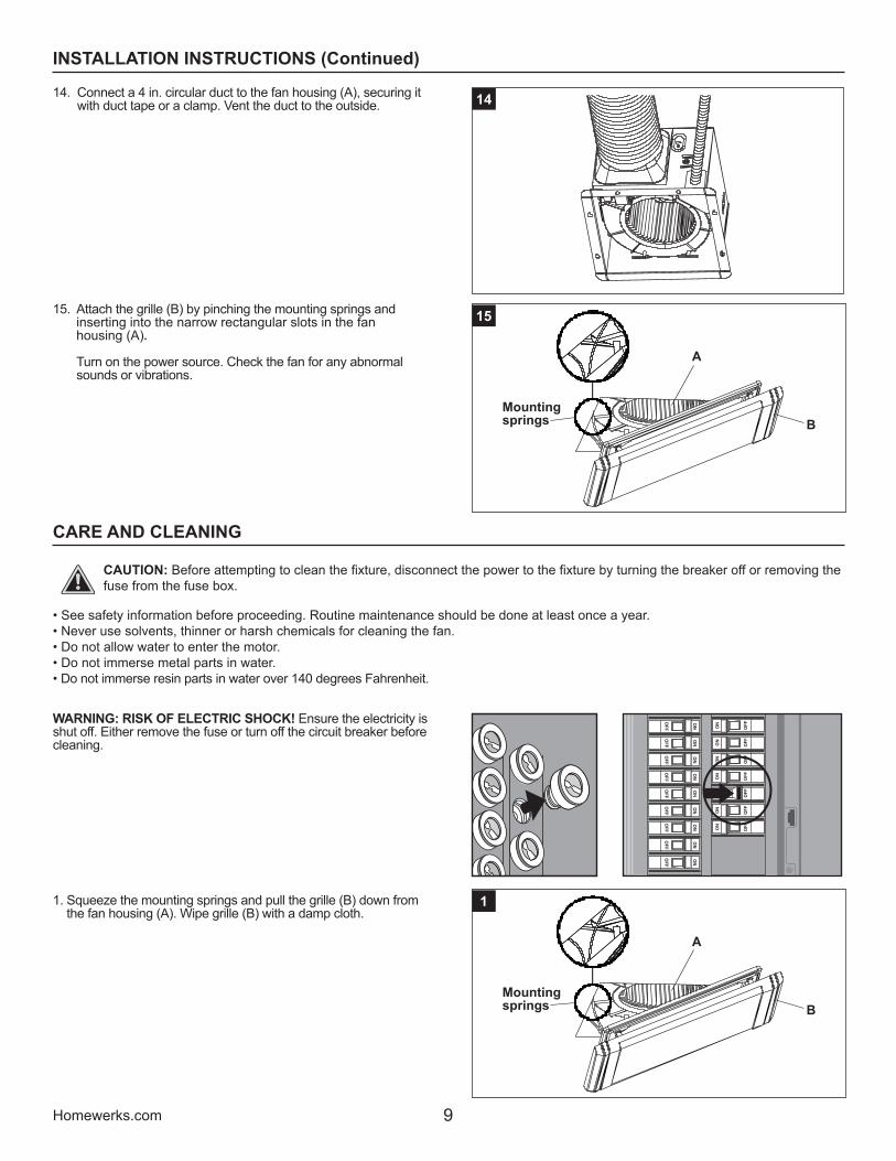
14. Connect a 4 in. circular duct to the fan housing (A), securing it with duct tape or a clamp. Vent the duct to the outside. 14
15. Attach the grille (B) by pinching the mounting springs and inserting into the narrow rectangular slots in the fan housing (A). Turn on the power source. Check the fan for any abnormal sounds or vibrations.
15
Mounting springs
A
B
CARE AND CLEANING
CAUTION: Before attempting to clean the fixture, disconnect the power to the fixture by turning the breaker off or removing the fuse from the fuse box.
• See safety information before proceeding. Routine maintenance should be done at least once a year.• Never use solvents, thinner or harsh chemicals for cleaning the fan.• Do not allow water to enter the motor.• Do not immerse metal parts in water.• Do not immerse resin parts in water over 140 degrees Fahrenheit.
WARNING: RISK OF ELECTRIC SHOCK! Ensure the electricity is shut off. Either remove the fuse or turn off the circuit breaker before cleaning.
1. Squeeze the mounting springs and pull the grille (B) down from the fan housing (A). Wipe grille (B) with a damp cloth.
1
Mounting springs
A
B
10 Homewerks.com
TROUBLESHOOTING
PROBLEM POSSIBLE CAUSE SOLUTION
The fan seems louder than it should.
The CFM is too great for the space. Be sure the CFM rating on the fan matches the square footage of your room.
The damper is damaged or not working properly. Check the damper to ensure it is opening and closing properly. If the damper has become damaged, please call Customer Service.
The bend in the duct is too close to the fan discharge. Be sure you do not have any sharp bends in the duct within 18 in. of the fan discharge.
The fan discharge is reduced to fit a smaller duct. Use the recommended size ducting to reduce fan noise.
The fan body is not attached securely. Be sure the fan is securely attached to the ceiling joists.
The fan is not clearing humidity from the room.
There is insufficient airflow intake in the room. Be sure a door or window is slightly ajar or open to allow airflow. The fan is not able to draw air out of the room without enough airflow.
There is insufficient CFM.NOTE: Using a tissue is not the correct method for determining if the fan is operating properly. If the fan clears steam from the room within approximately 15 minutes of completing your shower, then the fan is operating properly.
Be sure the CFM rating of the fan matches the square footage of your room.
2. Remove dust and dirt from the fan housing (A) with a vacuum cleaner. 2
A
3. Wipe the fan housing (A) with a damp cloth and wipe dry. 3A
4. Attach the grille (B) by pinching the mounting springs and insert-ing them into the narrow rectangular slots in the fan housing (A). Turn on power source. Test the unit.
4
Mounting springs
A
B
CARE AND CLEANING (continued)
11Homewerks.com
¿Tiene preguntas, problemas, o faltan piezas? Antes de regresar a la tienda, llame al Servicio al Cliente, 1-877-319-3757, de lunes a viernes, de 7:30 a.m. a 4:30 p.m., hora estándar central.
CONSERVE ESTE MANUAL PARA USO FUTURO
VENTILADOR DE BAÑO
MODELO 7107-03HW
12 Homewerks.com
TABLA DE CONTENIDO
Cumplimiento UL .............................................................................................................................................................12
Especificaciones del producto ..........................................................................................................................................12
Contenido del paquete .....................................................................................................................................................13
Información sobre seguridad ............................................................................................................................................14
Instrucciones de installación.............................................................................................................................................16
Cuidado y limpieza ...........................................................................................................................................................19
Solución de problemas .....................................................................................................................................................20
CUMPLIMIENTO UL
El B-1 del ensamblaje de rueda del motor del ventilador se combina en la carcasa B del motor del ventilador, que se instala en la abertura del techo.Estos componentes cumplen con el archivo UL 507: Sección 10.6, Sección 62.2.3, Sección 62.4.1 y Sección 64A.9.
ESPECIFICACIONES DEL PRODUCTO
Flujo de aire: 110 CFM Volumen sonoro: 1,0 sone120 V, 60Hz Consumo eléctrico del motor: 30 W Diámetro del conducto: 4 pulg. Peso: 6,4 kg
GARANTÍA LIMITADA DE 3 AÑOSSi el ventilador falla debido a un defecto en el material o la mano de obra en cualquier momento durante los primeros TRES años de poseerlo, elfabricante lo reemplazará sin cargos y con el franqueo pagado a su discreción. Esta garantía no cubre productos que hayan sido objeto de abuso, alteración, daño, mal uso, corte o desgaste. Esta garantía no cubre el uso en aplicaciones comerciales. Utilice únicamente piezas de repuesto de reparación originales provistas por el fabricante para reparar este ventilador. El uso de piezas de repuesto que no sean originales anulará su garantía. El fabricante RECHAZA todas las demás garantías implícitas o expresas, incluidas todas las garantías de comercialización y / o idoneidad para un propósito particular. Como algunos estados no permiten exclusiones o limitaciones en una garantía implícita, las exclusiones y limitaciones anteriores pueden no aplicarse. Esta garantía le otorga derechos legales específicos y es posible que tenga otros derechos que varían de un estado a otro. Esta garantía se limita únicamente al reemplazo de piezas defectuosas. Se excluyen los cargos de mano de obra y / o daños incurridos durante la insta-lación, reparación, reemplazo, así como daños incidentales y consecuentes relacionados con lo anterior. Cualquier daño a este producto como resultado de negligencia, mal uso, accidente, instalación o uso incorrecto que no sea el propósito DEBERÍA ANULAR ESTA GARANTÍA. Los costos de envío para el producto devuelto como parte de una reclamación de la garantía deben ser pagados por el cliente. Las consultas sobre reclamaciones de garantía pueden dirigirse al 1-877-319-3757, de lunes a viernes de 7:30 a.m. a 4:30 p.m., hora estándar central.
13Homewerks.com
CONTENIDO DEL PAQUETE
MATERIALES INCLUIDOS (no se ilustran en tamaño real)
AA BB CC
Tornillo para maderaM4 x 30mm
Tornillo para metales M4 x 12mm
Tornillo para metales M4 x 10mm
Cant. 8 Cant. 2 Cant. 1
PARTE DESCRIPCIÓN CANT.A Carcasa del ventilador 1B Rejilla 1C Soporte de suspensión 1
PARTE DESCRIPCIÓN CANT.D Soporte de suspensión 1E Soporte de suspensión 1
AC
D
E
B
14 Homewerks.com
INFORMACIÓN SOBRE SEGURIDAD
Por favor, lea y comprenda este manual en su totalidad antes de intentar de ensamblar, operar o instalar el producto.• Siempre desconecte la fuente de alimentación antes de darle
servicio al ventilador, motor o caja eléctrica.• Siga todos los codigos locales de construccion,
de seguridad y electricos asi como el NEC (Codigo Electrico Nacional) y OSHA (Ley de Salud y Seguridad Ocupacional).
• El suministro del servicio electrico debe ser de 120 voltios, 60 hertz.
• Este producto debe estar correctamente conectado al conductor de conexion a tierra del circuito de alimentacion.
• No doble ni retuerza los cables de energia.• No use este ventilador con ningún dispositivo de control de
estado sólido, como un control remoto, interruptor de atenu-ación o ciertos temporizadores. Los temporizadores mecáni-cos no son dispositivos de estado sólido.
• No instale en un techo con aislamiento mayor de R40.• Conductos se deben instalar en una línea recta con curvas
mínimas.• El tamaño del conducto debe ser de mismo tamaño que la
descarga y no debe ser reducido. Reducir el tamaño del conducto puede aumentar el ruido del ventilador.
ADVERTENCIA: Para reducir el riesgo de incendio, choque eléctrico o lesiones a las personas, respete lo siguiente:
1. Use esta unidad en la manera prevista por el fabricante. Si tiene alguna pregunta, por favor llame al Servicio al Cliente.
2. Antes de dar servicio o limpiar esta unidad apague la fuente de alimentación en el panel y bloquélo para evitar que se encendia la alimentación accidentalmente. Si no puede bloquear el panel, marque claramente el panel con una etiqueta de advertencia para evitar que se encienda la alimentación.
3. El trabajo de instalación y el cableado eléctrico debe ser hecho por una persona calificada, de acuerdo con todos los códigos y normas aplicables, incluyendo la construcción con clasificación ignífuga.
4. Se necesita suficiente aire para una combustión apropiada y el escape de los gases a través del conducto (chimenea) del equipo que quema combustible para evitar contratiraje. Siga las guias del fabricante de equipo de calefacción y las normas de seguridad como las publicadas de la Asociación Nacional de Protección contra Incendios (NFPA), y de la Sociedad Estadounidense de Ingenieros en Calefacción, Refrigeración y Aire Acondicionado (ASHRAE), y las autoridades de código local.
5. Cuando corte o perfore en la pared o techo, no dañe el cableado eléctrico u otros servicios ocultos.
6. Los ventiladores con conductos siempre deben ser ventilados al exterior.
7. Si esta unidad se va a instalar sobre una bañera o ducha, se debe marcar según sea apropiado para la aplicación y conectarse a un circuito de derivación protegido GFCI (Interruptor de circuito de falla a tierra).
8. Este ventilador está diseñado para instalarse por lo menos a 1 m del cabezal de la ducha cuando se instala sobre una bañera o ducha. La instalación dentro de una cabina de ducha no se recomienda a menos que se pueda alcanzar la distancia de 1 m.
PRECAUCIÓN
• Para uso de ventilación general solamente. No lo use para desalojar materiales y vapores peligrosos o explosivos.
• No debe usarse en cocina.• Para reducir el riesgo de lesiones a las personas,
instale el ventilador al menos a 7 pies (2.1m) sobre el piso.
PRECAUCIÓN: La instalación de esta unidad requiere que la energía esté apagada hasta que se complete la instalación. Si encuentra problemas con la unidad que no se enciende, revise la sección de solución de problemas del manual de instrucciones. Si necesita asistencia adicional, llame al 1-877-319-3757, de 7:30 a.m. a 4:30 p.m., HCE, de lunes a viernes. NO REGRESE A LA TIENDA.
PREPARACIÓN
Antes de comenzar a ensamblar este producto, asegurese de que todas las piezas esten presentes. Compare las piezas con la lista de contenido del paquete y herraje incluido. Si hace falta alguna pieza o se encuentra danada, no intente ensamblar el producto. Pongase en contacto con el Servicio al Cliente para piezas de repuesto 1-877-319-3757, de 7:30 a.m. a 4:30 p.m., hora central estándar, de lunes a viernes.Herramientas necesarias para armar (no incluidas): Martillo, destornillador de cabeza plana, conectores de cables, clavos, cinta adhesiva, destornillador de estrella, y cuchillo multiuso o sierra para paneles de yeso.Herramientas útiles (no incluidas): Taladro eléctrico, brocas de taladro ADVERTENCIA: ¡RIESGO DE DESCARGA ELECTRIC! Asegurese de cortar el suministro eléctrico en los cables con los que trabajara. Extraiga los fusibles o apague el cortacircuitos antes de quitar el ventilador de baño existente o instalar uno nuevo.
Antes de quitar su ventilador actual, verifique que su caja de interruptores en la pared tenga los cables de suministro necesarios para esta instalación. Estos cables de alimentación (negro) y neutro (blanco) como se muestra en el diagrama de cableado a continuación. Si no ve estos dos cables, consulte a un electricista autorizado.
Compruebe el área sobre la ubicación de instalación para asegurarse de que el cableado puede correr a la ubicación prevista y que los conductos se puede correr y el área es suficiente para una ventilación adecuada.Inspeccione los conductos y el cableado antes de proceder con la instalación.Antes de la instalación, proporcione acceso para la inspección y el mantenimiento en un lugar que no interfiera con el trabajo de instalación.Es posible que necesite la ayuda de una segunda persona para instalar este ventilador; una en el lado del ático y otra en el lado de la habitación.La instalacion puede variar dependiendo de cómo se instaló el ventilador anterior. Los suministros necesarios para la instalación de su ventilador de baño no están todos incluidos; sin embargo, la mayoría están disponibles en su tienda de artículos del hogar o ferretería local.
15Homewerks.com
El conducto de este ventilador al exterior del edificio tiene un fuerte efecto en el flujo del aire, ruido y uso de energía del ventilador. Use la orientación del conducto más corta y recta posible para un mejor desempeño, y evite instalar el ventilador con conductos más pequeños que los recomendados. La instalación alrededor de los conductos puede reducir la pérdida de energía e inhibir el crecimiento de moho. Es posible que los ventiladores instalados con conductos existentes no logren su flujo de aire nominal.
INSTALACIÓN TÍPICA
Carcasa del ventilador
Aísle adecuadamentealrededor del ventiladorpara minimizar lapérdida y gananciade calor del edificio
Selle cualquierespacio alrededorde la carcasadel ventilador
Tendido rectode 2 a 3 piesantes del codo
Las piezas cortas de conducto flexible ayudan a alinear y absorber el sonido
Tapa de techo(con amortiguadorincorporado)
Calafatear la terminación al conducto
Tapa depared (conamortiguadorincorporado)
DIMENSIONESAperturo
de techo (La) Aperturo
de techo (An) Aperturo
de techo (Al) Dimensiones de
caja (La)Dimensiones de
caja (An)Dimensiones de
caja (Al)27,4 cm 26,7 cm 21,6 cm 26 cm 26 cm 20,3 cm
CABLEADOTodo el cableado debe estar conectada para una funcionalidad completa.
ADVERTENCIA: El cableado debe cumplir todos los códigos eléctricos aplicables. Desconecte la energía antes de retirar o instalar los conectores.
ADVERTENCIA: COBRE A COBRE SOLAMENTE. No utilice cables de aluminio.
PRECAUCIÓN: El accesorio (conector rápido) debe cumplir con las instrucciones de instalación a continuación.
NOTA: El conector es reutilizable en cables sólidos del mismo o más pequeño calibre. No reutilice el conector en cables trenzados.
Pele los cables de 3/8 pulg. a 1/2 pulg.Sujete con firmeza el cable y empuje el extremo pelado del cable en el puerto abierto del conector. Use solo un conductor por puerto.Verifique que el extremo pelado de los cables esté completamente inserto en la parte posterior del conector.
PRECAUCIÓN: Temperatura máxima del cableado: 105˚C (221˚F). Máximo 600 V para cableado de edificios y 1,000 V máximo para letreros y lámparas. El rango de cable aceptable es 18-16 AWG, cobre sólido.
16 Homewerks.com
INSTRUCCIONES DE INSTALACIÓN
PREVIO A LA INSTALACIÓNADVERTENCIA: ¡RIESGO DE DESCARGA ELECTRICA! Asegurese de cortar el suministro electrico en los cables con los que trabajara. Extraiga los fusibles o apague el cortacircuitos antes de quitar el ventilador de baño existente o instalar uno nuevo.
1. Retire el ventilador existente. Si no está reemplazando un ventilador existente, vaya al paso 12.
1
2. Mida la abertura para asegurarse de que sea suficientemente larga para acomodar la carcasa del ventilador nuevo (A) 26 cm x 26 cm.
2
3. Si este ventilador no reemplaza a uno viejo, corte una abertura de 27,4 cm x 26,7 cm para la carcasa del ventilador (A).
3
27,4 cm
26,7 cm
4. Retire los tornillos que sujetan el conector del conducto a la carcasa del ventilador (A), dejando los tornillos a un lado para usarlos más tarde. Luego retire el conector del conducto de la carcasa del ventilador (A). Inserte la carcasa del ventilador (A) en la abertura cortada en el panel de yeso.
4
Conectorde conducto
A
17Homewerks.com
INSTRUCCIONES DE INSTALLACIÓN (Continuación)Instalación con espacio de 30,5 cm entre las vigas del techo:5. Fije la carcasa del ventilador (A) a la viga del techo con 4 tornil-
los largos para madera (AA). Vaya al paso 12.
5
A
AA
0.24 pulg.Viga
Tabla deltecho
Instalación con espacio desde más de 30,5 cm a menos de 54 cm entre las vigas del techo:6. Inserte el soporte de suspensión (C) en las pestañas en el
lado conducto de la caja del ventilador (A). Inserte el soporte de suspensión (D) en las pestañas en el lado opuesto de la caja del ventilador (A).
46 C
D
7. Coloque la carcasa del ventilador (A) al lado de una viga de techo. La carcasa del ventilador (A) debe estar nivelada y perpendicular a la viga. Permite el espesor de la placa para techo usado en su aplicación. Coloque la carcasa del ventilador (A) de modo que el borde inferior de la carcasa del ventilador (A) quede al ras con la placa del techo. No monte al ras la caja del ventilador (A) en la viga.
7
12
A
8. Fije el extremo del soporte de suspensión (C) y el soporte de suspensión (D) a la viga del techo con tornillos para madera (AA). Vaya al paso 10.
8
D
DAA
AA
Instalación con espacio desde más de 53,3 cm a menos de 60,1 cm entre las vigas del techo:9. Inserte el soporte de suspensión (C) en las pestañas en el
lado conducto de la carcasa del ventilador (A). Inserte el soporte de suspensión (D) en las pestañas en el lado opuesto de la carcasa del ventilador (A) y luego deslice el soporte de suspensión (E) en el soporte de suspensión (D).
9
E C
D
18 Homewerks.com
INSTRUCCIONES DE INSTALLACIÓN (Continuación)
10. Coloque la caja del ventilador (A) de modo que el borde inferior de la caja del ventilador (A) quede al ras con la placa del techo. No monte al ras la caja del ventilador (A) en la viga. Fije el extremo de cada uno de los soportes de suspensión (C, D, E) a las vigas del techo con tornillos para madera (AA).
10 AA
E D
A
C
11. Fije los soportes de suspensión (D, E) a la carcasa del ven-tilador (A) utilizando tornillos para metales (BB) y asegure el soporte de suspensión (C) a la carcasa del ventilador (A) utilizando tornillos para metales (CC).
E
C
CC
BB
A
D
11
12. Una el conector del conducto a la caja del ventilador (A) con los tornillos que se dejaron de lado cuando el conector del conducto se retiró antes.
12
A
13. Retire la cubierta de la caja eléctrica de la caja del ventilador (A). Tire de los cables de la casa a través de la tapa la caja eléctrica. Usando los conectores rápidos, conecte el cableado de la casa al la caja del ventilador (A). 14 AWG es el conductor más pequeño que debe usarse para el cableado del circuito derivado. Consulte el diagrama de cableado en la página 16 para asegurarse de que se están realizando las conexiones de cables correctas. Empuje con cuidado las conexiones de cables en la caja eléctrica y vuelva a colocar la tapa de la caja eléctrica.
PRECAUCIÓN: Si los cables eléctricos e la casa no co-inciden con los colores enumerados en la página 16, debe determinar lo que representa cada cable de la casa antes de conectarlos. Es posible que deba consultar con un contratista eléctrico para hacer la determinación con seguridad.
13 Connector rápido
A
Cubierta de lacaja eléctrica
Cubierta de lacaja eléctrica
19Homewerks.com
INSTRUCCIONES DE INSTALLACIÓN (Continuación)
14. Conecte un conducto circular de 4 pulg y ventile hacia el fuera. Asegure con cinta adhesiva o abrazadera. 14
15. Coloque la rejilla (B) pellizcando los resortes de montaje y se insertan en las ranuras rectangulares estrechas en la carcasa del ventilador (A). Encienda la fuente de alimentación. Pruebe el ventilador en busca de sonido o vibración anormales.
15
Resortesde montaje
A
B
CUIDADO Y LIMPIEZA
PRECAUCIÓN: Antes de limpiar el aparato, desconecte el suministro electrico hacia este apagando el cortacircuitos o extrayendo el fusible de la caja de fusibles.
• Consulte informacion sobre seguridad antes de proceder. Se debe hacer mantenimiento de rutina al menos una vez al ano.• Nunca use solventes, diluyentes o productos quimicos fuertes para limpiar el ventilador.• No permita que entre agua al motor.• No sumerja las piezas de metal en agua.• No sumerja las piezas de plástico en agua a más de 140 ° F.
ANTES DE LIMPIARADVERTENCIA: ¡RIESGO DE DESCARGA ELECTRICA! Asegúrese de que la energía esté apagada. Quite el fusible o apague el disyuntor antes de limpiarlo.
1. Apriete los resortes de montaje y tire la rejilla (B) hacia abajo la carcasa del ventilador (A). Limpie la rejilla (B) con un paño húmedo.
1
Resortesde montaje
A
B
20 Homewerks.com
CUIDADO Y LIMPIEZA (Continuación)
2. Use una aspiradora para eliminar el polvo y la suciedad de la carcasa del ventilador (A).. 2
3. Limpie la carcasa del ventilador (A) con un paño húmedo y seque con un paño. 3
4. Coloque la rejilla (B) pellizcando los resortes de montaje y se insertan en las ranuras rectangulares estrechas en la carcasa del ventilador (A). Encienda la fuente de alimentación. Pruebe el ventilador. .
4
Resortesde montaje
A
B
SOLUCIÓN DE PROBLEMAS
PROBLEMA CAUSA POSIBLE SOLUCIÓN
El ventilador parece hacer más ruido del que deberia ser.
Los pies cúbicos por minuto (CFM) son demasiado grandes.
Asegúrese de que la calificación CFM del ventilador coincide con el tamaño de su habitación.
El regulador de tiro está dañado o no está funcionando adecuadamente.
Compruebe amortiguador para asegurarse de que se está abriendo y cerrando correctamente. Si el regulador de tiro se ha dañado, por favor llame a Servicio al Cliente.
La curva en el conducto está demasiado cerca de la descarga del ventilador.
Asegúrese de que usted no tiene ningún doblez en cerca del conducto de 18 pulgadas a la descarga del ventilador.
Descarga del ventilador reducida para que quepa más pequeño conducto.
Use el tamaño recomendado conducto para reducir el ruido del ventilador.
La carcasa del ventilador no está instalada de forma segura.
Asegúrese de que el ventilador está bien conectado a las vigas del techo.
El ventilador no está despejando la humedad de la habitación.
No hay suficiente flujo de aire de admisión en la habitación.
Asegúrese de una puerta o ventana está entreabierta o abierta para permitir el flujo de aire. El ventilador no es capaz de extraer el aire de la habitación sin flujo de aire suficiente para aprovechar.
Los CFM no son suficientes.NOTA: El uso de un pañuelo no es el método correcto para determinar si el ventilador está funcionando adecuadamente. Si el ventilador despeja vapor de la habitación en aproximadamente 15 minutos después de terminar con su ducha, entonces el ventilador está funcionando adecuadamente.
Asegúrese de que la capacidad nominal de CFM en el ventilador coincida con la superficie de su habitación.