Kurz- beschreibung Brief description MPA-Ventilinsel mit AS-Interface Typ VMPA-ASI- EPL-...-8E8A-Z EPL-...-8E8A-CE MPA valve terminal with AS-Interface type VMPA-ASI- EPL-...-8E8A-Z EPL-...-8E8A-CE – Deutsch – English – Español – Français – Italiano – Svenska 758253 1104b Ventilinsel MPA
Die Ventilinseln Typ VMPA-ASI-EPL-...-8E8A-Z undVMPA-ASI-EPL-...-8E8A-CE sind ausschließlich zur Steuerungvon pneumatischen Aktuatoren bestimmt und nur für denEinsatz in Bussystemen gemäß der AS-Interface-Spezifika-tion geeignet.
VMPA-ASI-EPL-...-8E8A-Z kommt dabei als Standard-Slavezum Einsatz, VMPA-ASI-EPL-...-8E8A-CE als Slave für denExtended Address Mode.
Die Ventilinseln enthalten 2 AS-Interface-Slaves, hier als„Slave 1“ und „Slave 2“ bezeichnet. Sie verhalten sich amAS-Interface-Bus wie 2 einzelne Ventilinseln mit je 4 Ein-und Ausgängen. Die Ventilinseln ermöglichen damit die An-steuerung von 8 Ventilmagnetspulen und die Erfassung von8 Sensoren. Zum Anschluss der Sensoren wird die wechsel-bare Anschlusstechnik des CPX-Systems unterstützt.
Beim Anschluss handelsüblicher Zusatzkomponenten sinddie angegebenen Grenzwerte für Drücke, Temperaturen,elektrische Daten, Momente usw. einzuhalten.
AS-Interface-Bussysteme und Ventilinseln dürfen nur vonhierfür geschultem Fachpersonal installiert werden. Angabenzur Konzeption und Adressierung Ihres Bussystems findenSie in der Beschreibung Ihres AS-Interface-Masters.
Ausführliche Informationen zur Pneumatik der Ventilinselfinden Sie in der Pneumatik-Beschreibung Typ P.BE-MPA-...
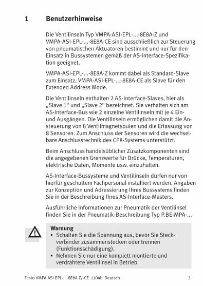
Warnung� Schalten Sie die Spannung aus, bevor Sie Steck-verbinder zusammenstecken oder trennen(Funktionsschädigung).
� Nehmen Sie nur eine komplett montierte undverdrahtete Ventilinsel in Betrieb.
Festo VMPA-ASI-EPL-...-8E8A-Z/-CE 1104b Deutsch4
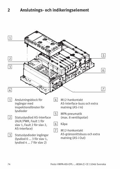
2 Anschluss- und Anzeigeelemente
1214
In
Out
AuxPwrFault
1
AS-i
01
23
4
DI
X1
X2
X3
X4
2Fault
56
78
5
1
2
3
4 7
6
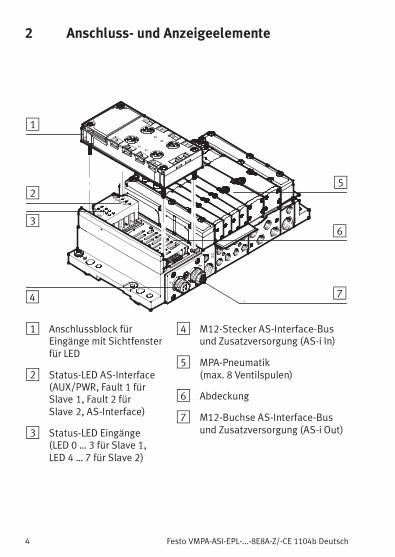
1 Anschlussblock fürEingänge mit Sichtfensterfür LED
Beispiele für Kombinationen der elektrischenMPM-Verkettungen
Ausgänge (A0 … A7) 0 1 2 3 4 5 6 7
MPA2: 4 Spulen / MPA2: 2x2 Spulen 3 1 1
MPA2: 2 / MPA2: 4 / MPA2: 2 Spulen 1 3 1
MPA2: 2x2 Spulen / MPA2: 4 Spulen 1 1 3
MPA2: 4x2 Spulen 1 1 1 1
MPA1: 2x4 Spulen 2 3
MPA1: 4 Spulen / MPA2: 4 Spulen 2 3
MPA2: 4 Spulen / MPA1: 4 Spulen 3 2
MPA2: 2x4 Spulen 3 3
MPA1: 8 Spulen 4
Zuordnungen der Ventile
1 ...-EV-AB-2: Bestückung mit MPA2-M, J, N, K, H, B, G, E, D, X, W, L - 2 Ventilscheiben
2 ...-EV-AB-4: Bestückung mit MPA1-M, X, W, L - 4 Ventilscheiben
3 ...-EV-AB-4: Bestückung mit MPA2-M, J, N, K, H, B, G, E, D, X, W, L - 2 Ventilscheiben
4 ...-EV-AB-8: Bestückung mit MPA1-M, X, W, L - 8 Ventilscheiben
Festo VMPA-ASI-EPL-...-8E8A-Z/-CE 1104b Deutsch12
3.6 AS-Interface-Bus und Lastspannung anschließen
Über den AS-Interface-Bus wird die Sensorversorgung fürdie Eingänge bereit gestellt.
WarnungVerwenden Sie ausschließlich Stromquellen, die einesichere elektrische Trennung der Betriebsspannungnach IEC/DIN EN 60204-1 gewährleisten.Berücksichtigen Sie zusätzlich die allgemeinenAnforderungen an PELV-Stromkreise gemäßIEC/DIN EN 60204-1.
HinweisDie aus der AS-Interface-Spannungsversorgung ge-wonnene Sensorversorgung ist vor Kurzschlüssenund Überlast geschützt. Sie darf nichtmit anderenPotentialen verbunden werden (beispielsweise gemein-same Masse).Die Ventile (Ausgänge) werden immer mit Zusatz-versorgung 24 V, getrennt über den Lastspannungs-anschluss, betrieben.
Beachten Sie bei Stichleitungen:
– die maximale Gesamtlänge des AS-Interface-Bus(100 m ohne Repeater/Extender)
– die Leitungslänge des Lastspannungsanschlusses(abhängig von der Stromaufnahme der Ventilinsel undden Schwankungen der Lastspannung)
Adresse, Watchdog, EA-Status– Zusatzversorgung fehlt oder
Unterspannung, Peripheriefehler
LED-Anzeige
LED-Anzeige
1) Die Eingänge sind kurzschlussfest. Bei Auftreten eines Kurzschlusseswird der Slave abgeschaltet. Der AS-Interface-Master sieht diesenSlave als fehlend. Wenn der Kurzschluss beseitigt ist, meldet sichder Slave sofort als funktionsfähig zurück.
HinweisFür den Einsatz von VMPA-ASI-EPL-...-8E8A-CEist mindestens AS-Interface-Master Version M3erforderlich.
Festo VMPA-ASI-EPL-...-8E8A-Z/-CE 1104b English 17
English1 User instructions
The valve terminals of type VMPA-ASI-EPL-...-8E8A-Z andVMPA-ASI-EPL-...-8E8A-CE have been designed exclusivelyfor controlling pneumatic actuators and are only suitable foruse in bus systems in accordance with the AS-Interfacespecification.
VMPA-ASI-EPL-...-8E8A-Z is used as a standard slave,VMPA-ASI-EPL-...-8E8A-CE as a slave for the ExtendedAddress mode.
The valve terminals contain 2 AS-Interface slaves, desig-nated here as “Slave 1” and “Slave 2”. They behave on theAS-Interface bus like two individual valve terminals, eachwith 4 inputs and 4 outputs. The valve terminals enable thecontrol of 8 valve solenoid coils and the registering of8 sensors. The exchangeable connections of the CPX systemare used for connecting the sensors.
If additional commercially-available components are con-nected, the specified limits for pressures, temperatures,electrical data, torques, etc. must not be exceeded.
AS-Interface bus systems and valve terminals may only beinstalled by personnel especially trained for this purpose.Specifications on the design and addressing of your bussystem can be found in the manual for the AS-Interfacemaster.
Detailed information on the pneumatic components of thevalve terminal can be found in the Pneumatics manual typeP.BE-MPA-...
Warning� Switch off the power supply before connecting ordisconnecting plug connectors (otherwise functionaldamage).
� Only commission a valve terminal that has beenmounted and wired completely.
Festo VMPA-ASI-EPL-...-8E8A-Z/-CE 1104b English18
2 Connection and display components
1214
In
Out
AuxPwrFault
1
AS-i
01
23
4
DI
X1
X2
X3
X4
2Fault
56
78
5
1
2
3
4 7
6
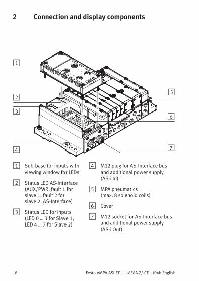
1 Sub-base for inputs withviewing window for LEDs
2 Status LED AS-Interface(AUX/PWR, fault 1 forslave 1, fault 2 forslave 2, AS-Interface)
3 Status LED for inputs(LED 0 … 3 for Slave 1,LED 4 … 7 for Slave 2)
4 M12 plug for AS-Interface busand additional power supply(AS-i In)
5 MPA pneumatics(max. 8 solenoid coils)
6 Cover
7 M12 socket for AS-Interface busand additional power supply(AS-i Out)
Festo VMPA-ASI-EPL-...-8E8A-Z/-CE 1104b English 19
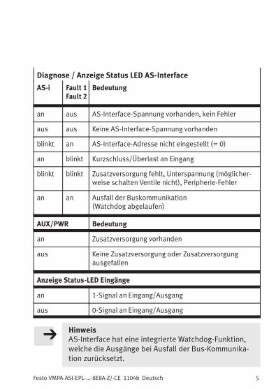
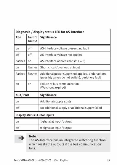
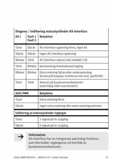
Diagnosis / display status LED for AS-Interface
AS-i Fault 1Fault 2
Significance
on off AS-Interface voltage present, no fault
off off AS-Interface voltage not applied
flashes on AS-Interface address not set ( = 0)
on flashes Short circuit/overload at input
flashes flashes Additional power supply not applied, undervoltage(possibly valves do not switch), periphery fault
on on Failure of bus communication(Watchdog expired)
AUX/PWR Significance
on Additional supply exists
off No additional supply or additional supply failed
Display status LED for inputs
on 1-signal at input/output
off 0-signal at input/output
NoteThe AS-Interface has an integrated watchdog functionwhich resets the outputs if the bus communicationfails.
Festo VMPA-ASI-EPL-...-8E8A-Z/-CE 1104b English20
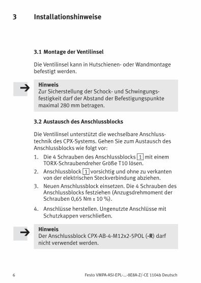
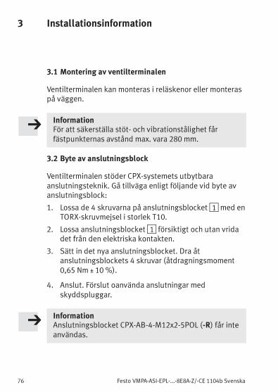
3 Installation instructions
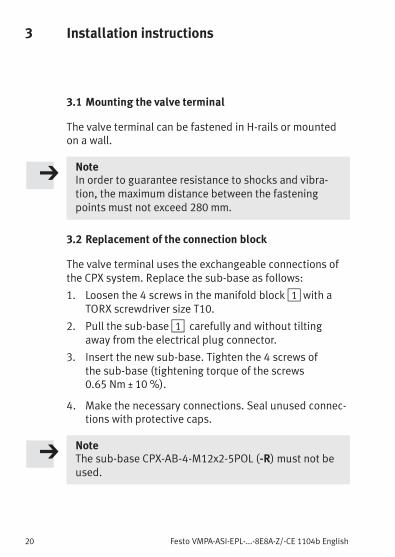
3.1 Mounting the valve terminal
The valve terminal can be fastened in H-rails or mountedon a wall.
NoteIn order to guarantee resistance to shocks and vibra-tion, the maximum distance between the fasteningpoints must not exceed 280 mm.
3.2 Replacement of the connection block
The valve terminal uses the exchangeable connections ofthe CPX system. Replace the sub-base as follows:
1. Loosen the 4 screws in the manifold block1 with aTORX screwdriver size T10.
2. Pull the sub-base1 carefully and without tiltingaway from the electrical plug connector.
3. Insert the new sub-base. Tighten the 4 screws ofthe sub-base (tightening torque of the screws0.65 Nm ± 10 %).
4. Make the necessary connections. Seal unused connec-tions with protective caps.
NoteThe sub-base CPX-AB-4-M12x2-5POL (-R) must not beused.
Festo VMPA-ASI-EPL-...-8E8A-Z/-CE 1104b English 21
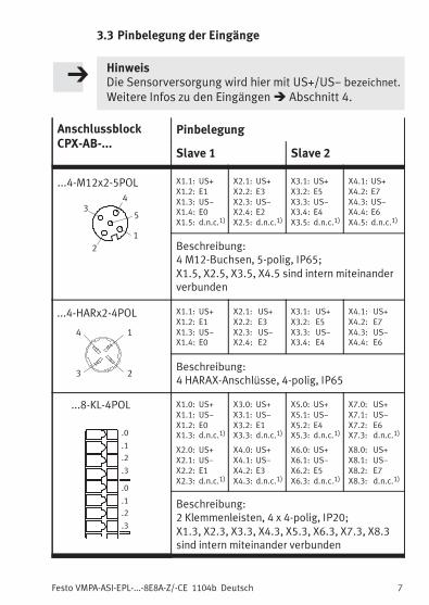
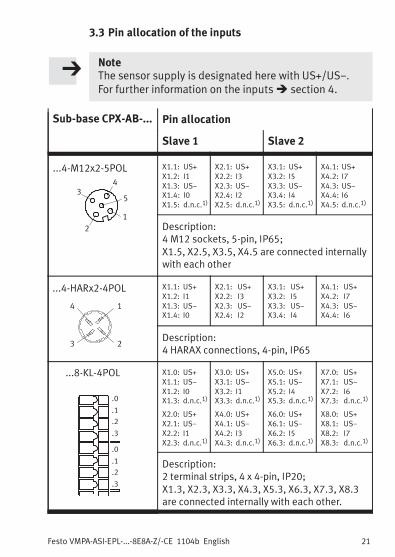
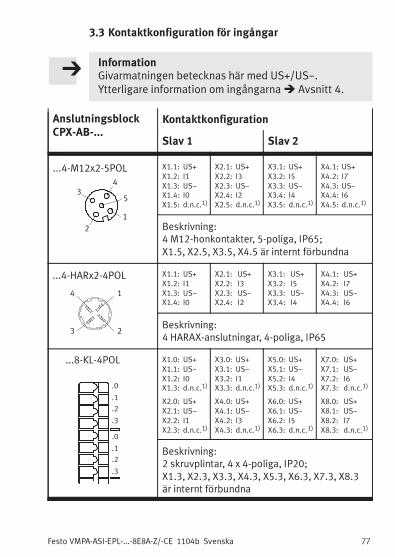
3.3 Pin allocation of the inputs
NoteThe sensor supply is designated here with US+/US−.For further information on the inputs� section 4.
Sub-base CPX-AB-... Pin allocation
Slave 1 Slave 2
...4-M12x2-5POL
2
3
1
5
4
X1.1: US+
X1.2: I1
X1.3: US−
X1.4: I0
X1.5: d.n.c.1)
X2.1: US+
X2.2: I3
X2.3: US−
X2.4: I2
X2.5: d.n.c.1)
X3.1: US+
X3.2: I5
X3.3: US−
X3.4: I4
X3.5: d.n.c.1)
X4.1: US+
X4.2: I7
X4.3: US−
X4.4: I6
X4.5: d.n.c.1)
Description:4 M12 sockets, 5-pin, IP65;X1.5, X2.5, X3.5, X4.5 are connected internallywith each other
...4-HARx2-4POL
23
14
X1.1: US+
X1.2: I1
X1.3: US−
X1.4: I0
X2.1: US+
X2.2: I3
X2.3: US−
X2.4: I2
X3.1: US+
X3.2: I5
X3.3: US−
X3.4: I4
X4.1: US+
X4.2: I7
X4.3: US−
X4.4: I6
Description:4 HARAX connections, 4-pin, IP65
...8-KL-4POL
.0
.1
.2
.3
.0
.1
.2
.3
X1.0: US+
X1.1: US−
X1.2: I0
X1.3: d.n.c.1)
X2.0: US+
X2.1: US−
X2.2: I1
X2.3: d.n.c.1)
X3.0: US+
X3.1: US−
X3.2: I1
X3.3: d.n.c.1)
X4.0: US+
X4.1: US−
X4.2: I3
X4.3: d.n.c.1)
X5.0: US+
X5.1: US−
X5.2: I4
X5.3: d.n.c.1)
X6.0: US+
X6.1: US−
X6.2: I5
X6.3: d.n.c.1)
X7.0: US+
X7.1: US−
X7.2: I6
X7.3: d.n.c.1)
X8.0: US+
X8.1: US−
X8.2: I7
X8.3: d.n.c.1)
Description:2 terminal strips, 4 x 4-pin, IP20;X1.3, X2.3, X3.3, X4.3, X5.3, X6.3, X7.3, X8.3are connected internally with each other.
Festo VMPA-ASI-EPL-...-8E8A-Z/-CE 1104b English22
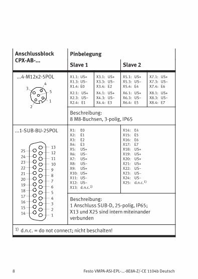
Sub-base CPX-AB-... Pin allocation
Slave 1 Slave 2
...4-M12x2-5POL
2
3
1
5
4
X1.1: US+
X1.3: US−
X1.4: I0
X2.1: US+
X2.3: US−
X2.4: I1
X3.1: US+
X3.3: US−
X3.4: I2
X4.1: US+
X4.3: US−
X4.4: I3
X5.1: US+
X5.3: US−
X5.4: I4
X6.1: US+
X6.3: US−
X6.4: I5
X7.1: US+
X7.3: US−
X7.4: I6
X8.1: US+
X8.3: US−
X8.4: I7
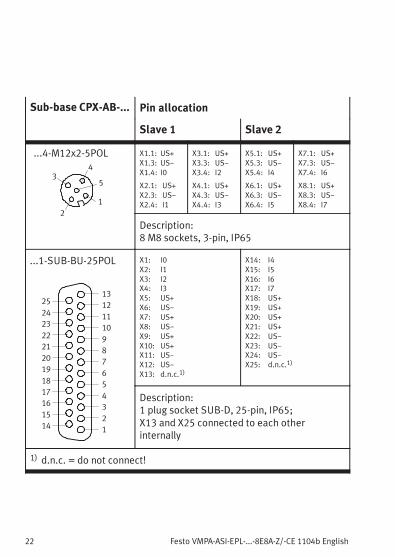
Description:8 M8 sockets, 3-pin, IP65
...1-SUB-BU-25POL
1
2
3
4
5
6
7
8
9
10
11
12
13
14
15
16
17
18
19
20
21
22
23
24
25
X1: I0
X2: I1
X3: I2
X4: I3
X5: US+
X6: US−
X7: US+
X8: US−
X9: US+
X10: US+
X11: US−
X12: US−
X13: d.n.c.1)
X14: I4
X15: I5
X16: I6
X17: I7
X18: US+
X19: US+
X20: US+
X21: US+
X22: US−
X23: US−
X24: US−
X25: d.n.c.1)
Description:1 plug socket SUB-D, 25-pin, IP65;X13 and X25 connected to each otherinternally
1) d.n.c. = do not connect!
Festo VMPA-ASI-EPL-...-8E8A-Z/-CE 1104b English 23
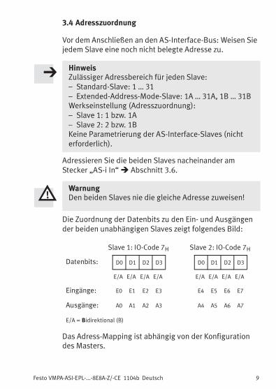
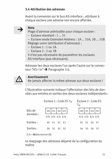
3.4 Address assignment
Before connecting to the AS-Interface bus: assign anunused address to each slave.
NotePermitted address range for each slave:– Standard slave: 1 … 31– Extended address mode slave: 1A … 31A, 1B … 31BFactory setting (address allocation):– Slave 1: 1 or 1A respectively– Slave 2: 2 or 1B respectivelyNo parametrisation of the AS-Interface slaves(not necessary).
Address both slaves one after the other at the plug“AS-i In”� section 3.6.
WarningNever assign the same address to both slaves.
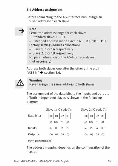
The assignment of the data bits to the inputs and outputsof both independent slaves is shown in the followingdiagram.
Slave 1: IO code 7H Slave 2: IO code 7H
Data bits: D0 D1 D2 D3 D0 D1 D2 D3
I/O I/O I/O I/O I/O I/O I/O I/O
Inputs: I0 I1 I2 I3 I4 I5 I6 I7
Outputs: O0 O1 O2 O3 O4 O5 O6 O7
I/O = Bidirectional (B)
The address mapping depends on the configuration of themaster.
Festo VMPA-ASI-EPL-...-8E8A-Z/-CE 1104b English24
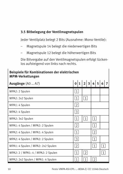
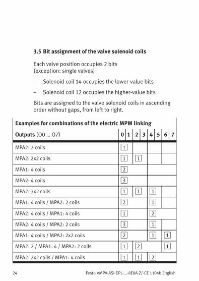
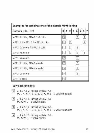
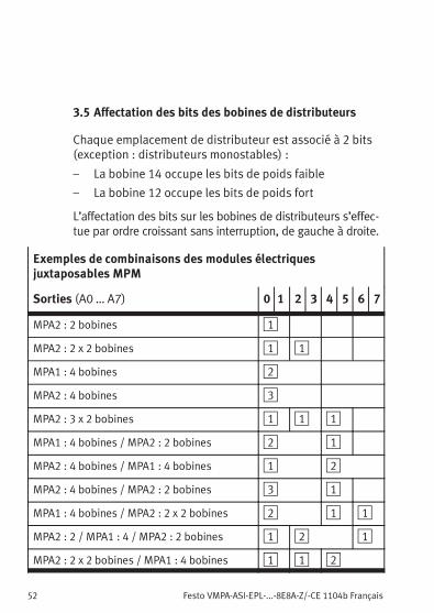
3.5 Bit assignment of the valve solenoid coils
Each valve position occupies 2 bits(exception: single valves)
– Solenoid coil 14 occupies the lower-value bits
– Solenoid coil 12 occupies the higher-value bits
Bits are assigned to the valve solenoid coils in ascendingorder without gaps, from left to right.
Examples for combinations of the electric MPM linking
Outputs (O0 … O7) 0 1 2 3 4 5 6 7
MPA2: 2 coils 1
MPA2: 2x2 coils 1 1
MPA1: 4 coils 2
MPA2: 4 coils 3
MPA2: 3x2 coils 1 1 1
MPA1: 4 coils / MPA2: 2 coils 2 1
MPA2: 4 coils / MPA1: 4 coils 1 2
MPA2: 4 coils / MPA2: 2 coils 3 1
MPA1: 4 coils / MPA2: 2x2 coils 2 1 1
MPA2: 2 / MPA1: 4 / MPA2: 2 coils 1 2 1
MPA2: 2x2 coils / MPA1: 4 coils 1 1 2
Festo VMPA-ASI-EPL-...-8E8A-Z/-CE 1104b English 25
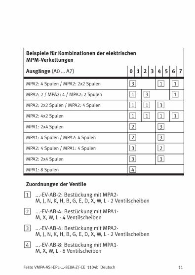
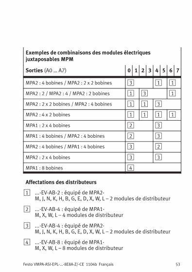
Examples for combinations of the electric MPM linking
Outputs (O0 … O7) 0 1 2 3 4 5 6 7
MPA2: 4 coils / MPA2: 2x2 coils 3 1 1
MPA2: 2 / MPA2: 4 / MPA2: 2 coils 1 3 1
MPA2: 2x2 coils / MPA2: 4 coils 1 1 3
MPA2: 4x2 coils 1 1 1 1
MPA1: 2x4 coils 2 3
MPA1: 4 coils / MPA2: 4 coils 2 3
MPA2: 4 coils / MPA1: 4 coils 3 2
MPA2: 2x4 coils 3 3
MPA1: 8 coils 4
Valve assignments
1 ...-EV-AB-2: Fitting with MPA2-M, J, N, K, H, B, G, E, D, X, W, L – 2 valve modules
2 ...-EV-AB-4: Fitting with MPA1-M, X, W, L – 4 valve slices
3 ...-EV-AB-4: Fitting with MPA2-M, J, N, K, H, B, G, E, D, X, W, L – 2 valve modules
4 ...-EV-AB-8: Fitting with MPA1-M, X, W, L – 8 valve slices
Festo VMPA-ASI-EPL-...-8E8A-Z/-CE 1104b English26
3.6 Connect the AS-Interface bus and the load voltage
The sensor supply for the inputs is provided via theAS-Interface bus.
WarningUse only power sources which guarantee a secureelectrical isolation of the operating voltage as perIEC/DIN EN 60204-1.Observe also the general requirements for PELV powercircuits as per IEC/DIN EN 60204-1.
NoteThe sensor supply gained from the AS-interfacepower supply is protected from short circuits andoverload. It must not be connected to other potentials(for example, common ground).The valves (outputs) are always supplied with 24 Vadditional supply, separate via the load voltageconnection.
Please note with branch lines:
– the maximum total length of the AS-Interface bus:(100 m without repeaters/extenders)
– the length of the load voltage connection cable(depends on the current consumption of the valveterminal and fluctuations in load voltage)
Festo VMPA-ASI-EPL-...-8E8A-Z/-CE 1104b English 27
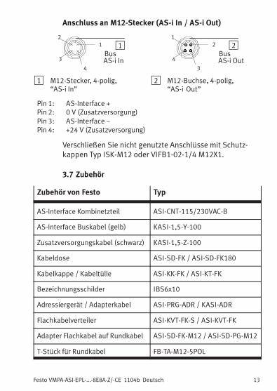
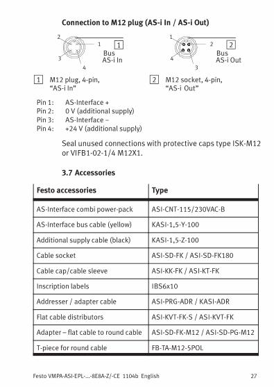
Connection to M12 plug (AS-i In / AS-i Out)
11
4
2
3BusAS-i In
22
3
1
4BusAS-i Out
1 M12 plug, 4-pin,“AS-i In”
2 M12 socket, 4-pin,“AS-i Out”
Pin 1: AS-Interface +Pin 2: 0 V (additional supply)Pin 3: AS-Interface −Pin 4: +24 V (additional supply)
Seal unused connections with protective caps type ISK-M12or VIFB1-02-1/4 M12X1.
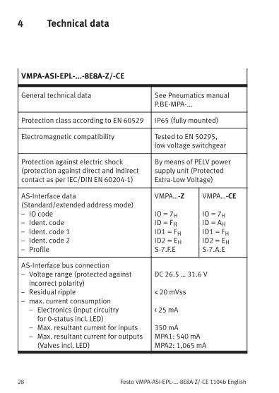
– Max. resultant current for inputs– Max. resultant current for outputs
(Valves incl. LED)
DC 26.5 … 31.6 V
≤ 20 mVss
< 25 mA
350 mAMPA1: 540 mAMPA2: 1,065 mA
Festo VMPA-ASI-EPL-...-8E8A-Z/-CE 1104b English 29
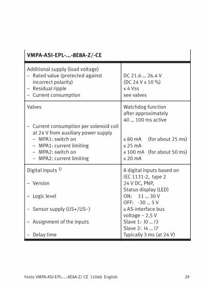
VMPA-ASI-EPL-...-8E8A-Z/-CE
Additional supply (load voltage)– Rated value (protected against
incorrect polarity)– Residual ripple– Current consumption
DC 21.6 … 26.4 V(DC 24 V ± 10 %)≤ 4 Vsssee valves
Valves
– Current consumption per solenoid coilat 24 V from auxiliary power supply– MPA1: switch on– MPA1: current limiting– MPA2: switch on– MPA2: current limiting
Watchdog functionafter approximately40 … 100 ms active
≤ 80 mA (for about 25 ms)≤ 25 mA≤ 100 mA (for about 50 ms)≤ 20 mA
Digital inputs 1)
– Version
– Logic level
– Sensor supply (US+/US−)
– Assignment of the inputs
– Delay time
8 digital inputs based onIEC 1131-2, type 224 V DC, PNP,Status display (LED)ON: 11 … 30 VOFF: -30 … 5 V≥ AS-interface busvoltage − 2,5 VSlave 1: I0 … I3Slave 2: I4 … I7Typically 3 ms (at 24 V)
Festo VMPA-ASI-EPL-...-8E8A-Z/-CE 1104b English30
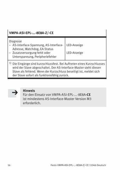
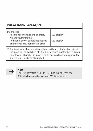
VMPA-ASI-EPL-...-8E8A-Z/-CE
Diagnostics– AS-Interface voltage and address,
watchdog, I/O status– Additional power supply not applied
or undervoltage, peripherals error
LED display
LED display
1) The inputs are short-circuit resistant. In the event of a short circuitthe slave will be switched off. The AS-Interface master then regardsthis slave as absent. The slave reports back as functioning once theshort circuit has been eliminated.
NoteFor use of VMPA-ASI-EPL-...-8E8A-CE at least theAS-Interface Master Version M3 is required.
Festo VMPA-ASI-EPL-...-8E8A-Z/-CE 1104b Español 31
Español1 Instrucciones para el usuario
Los terminales de válvulas tipo VMPA-ASI-EPL-...-8E8A-Z yVMPA-ASI-EPL-...-8E8A-CE han sido diseñados exclusiva-mente para el control de actuadores neumáticos y estáprevisto para ser utilizado solo en sistemas de bus,siguiendo las especificaciones del AS-Interface.
VMPA-ASI-EPL-...-8E8A-Z se utiliza como slave estándar yVMPA-ASI-EPL-...-8E8A-CE como slave para el ExtendedAddress Mode.
Los terminales de válvulas contienen 2 slaves AS-Interface,denominados “Slave 1” y “Slave 2”. En el bus AS-Interfacese comportan como 2 terminales de válvulas individualescon 4 entradas y 4 salidas cada uno. Los terminales deválvulas permiten controlar 8 bobinas de electroválvulas yregistrar 8 detectores. Para conectar los detectores, elterminal de válvulas soporta la tecnología de conexiónintercambiable del sistema CPX.
Si se conectan componentes disponibles comercialmentedeben respetarse los límites especificados para presiones,temperaturas, datos eléctricos, pares, etc.
Los sistemas de bus AS-Interface y terminales de válvulasdeben ser instalados por técnicos especializados. En elmanual del master AS-Interface pueden hallarse especifica-ciones detalladas sobre el diseño y el direccionamiento delsistema de master del AS-Interface.
Hallará información detallada sobre la parte neumática delterminal de válvulas en el manual de la parte neumáticatipo P.BE-MPA-...
Advertencia� Desconectar la tensión antes de enchufar o des-conectar conectores enchufables (esto evitará dañosfuncionales).
� Poner a punto el terminal de válvulas sólo cuando sehalle completamente montado y cableado.
Festo VMPA-ASI-EPL-...-8E8A-Z/-CE 1104b Español32
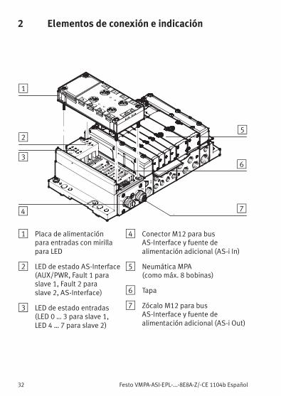
2 Elementos de conexión e indicación
1214
In
Out
AuxPwrFault
1
AS-i
01
23
4
DI
X1
X2
X3
X4
2Fault
56
78
5
1
2
3
4 7
6
1 Placa de alimentaciónpara entradas con mirillapara LED
2 LED de estado AS-Interface(AUX/PWR, Fault 1 paraslave 1, Fault 2 paraslave 2, AS-Interface)
3 LED de estado entradas(LED 0 … 3 para slave 1,LED 4 … 7 para slave 2)
4 Conector M12 para busAS-Interface y fuente dealimentación adicional (AS-i In)
5 Neumática MPA(como máx. 8 bobinas)
6 Tapa
7 Zócalo M12 para busAS-Interface y fuente dealimentación adicional (AS-i Out)
Festo VMPA-ASI-EPL-...-8E8A-Z/-CE 1104b Español 33
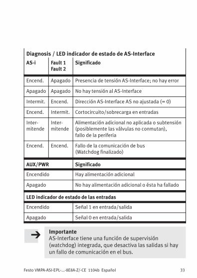
Diagnosis / LED indicador de estado de AS-Interface
AS-i Fault 1Fault 2
Significado
Encend. Apagado Presencia de tensión AS-Interface; no hay error
Apagado Apagado No hay tensión al AS-Interface
Intermit. Encend. Dirección AS-Interface AS no ajustada (= 0)
Encend. Intermit. Cortocircuito/sobrecarga en entradas
Inter-mitende
Inter-mitende
Alimentación adicional no aplicada o subtensión(posiblemente las válvulas no conmutan),fallo de la periferia
Encend. Encend. Fallo de la comunicación de bus(Watchdog finalizado)
AUX/PWR Significado
Encendido Hay alimentación adicional
Apagado No hay alimentación adicional o ésta ha fallado
LED indicador de estado de las entradas
Encendido Señal 1 en entrada/salida
Apagado Señal 0 en entrada/salida
ImportanteAS-Interface tiene una función de supervisión(watchdog) integrada, que desactiva las salidas si hayun fallo de comunicación en el bus.
Festo VMPA-ASI-EPL-...-8E8A-Z/-CE 1104b Español34
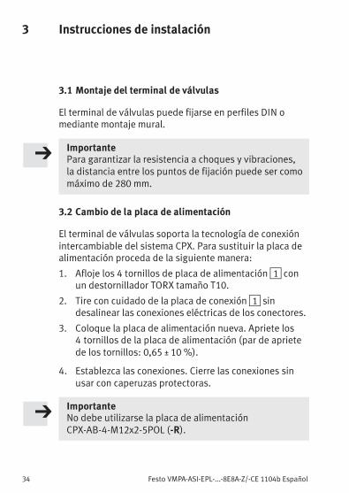
3 Instrucciones de instalación
3.1 Montaje del terminal de válvulas
El terminal de válvulas puede fijarse en perfiles DIN omediante montaje mural.
ImportantePara garantizar la resistencia a choques y vibraciones,la distancia entre los puntos de fijación puede ser comomáximo de 280 mm.
3.2 Cambio de la placa de alimentación
El terminal de válvulas soporta la tecnología de conexiónintercambiable del sistema CPX. Para sustituir la placa dealimentación proceda de la siguiente manera:
1. Afloje los 4 tornillos de placa de alimentación1 conun destornillador TORX tamaño T10.
2. Tire con cuidado de la placa de conexión1 sindesalinear las conexiones eléctricas de los conectores.
3. Coloque la placa de alimentación nueva. Apriete los4 tornillos de la placa de alimentación (par de aprietede los tornillos: 0,65 ± 10 %).
4. Establezca las conexiones. Cierre las conexiones sinusar con caperuzas protectoras.
ImportanteNo debe utilizarse la placa de alimentaciónCPX-AB-4-M12x2-5POL (-R).
Festo VMPA-ASI-EPL-...-8E8A-Z/-CE 1104b Español 35
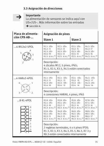
3.3 Asignación de direcciones
ImportanteLa alimentación de sensores se indica aquí conUS+/US−. Más información sobre las entradas� sección 4.
Descripción:2 regletas terminales, 4 x 4 pines IP20;X1.3, X2.3, X3.3, X4.3, X5.3, X6.3, X7.3 yX8.3 están conectados internamente
Festo VMPA-ASI-EPL-...-8E8A-Z/-CE 1104b Español36
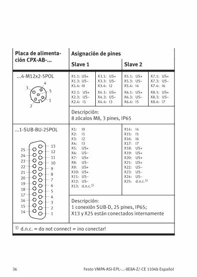
Placa de alimenta-ción CPX-AB-...
Asignación de pines
Slave 1 Slave 2
...4-M12x2-5POL
2
3
1
5
4
X1.1: US+
X1.3: US−
X1.4: I0
X2.1: US+
X2.3: US−
X2.4: I1
X3.1: US+
X3.3: US−
X3.4: I2
X4.1: US+
X4.3: US−
X4.4: I3
X5.1: US+
X5.3: US−
X5.4: I4
X6.1: US+
X6.3: US−
X6.4: I5
X7.1: US+
X7.3: US−
X7.4: I6
X8.1: US+
X8.3: US−
X8.4: I7
Descripción:8 zócalos M8, 3 pines, IP65
...1-SUB-BU-25POL
1
2
3
4
5
6
7
8
9
10
11
12
13
14
15
16
17
18
19
20
21
22
23
24
25
X1: I0
X2: I1
X3: I2
X4: I3
X5: US+
X6: US−
X7: US+
X8: US−
X9: US+
X10: US+
X11: US−
X12: US−
X13: d.n.c.1)
X14: I4
X15: I5
X16: I6
X17: I7
X18: US+
X19: US+
X20: US+
X21: US+
X22: US−
X23: US−
X24: US−
X25: d.n.c.1)
Descripción:1 conexión SUB-D, 25 pines, IP65;X13 y X25 están conectados internamente
1) d.n.c. = do not connect = ¡no conectar!
Festo VMPA-ASI-EPL-...-8E8A-Z/-CE 1104b Español 37
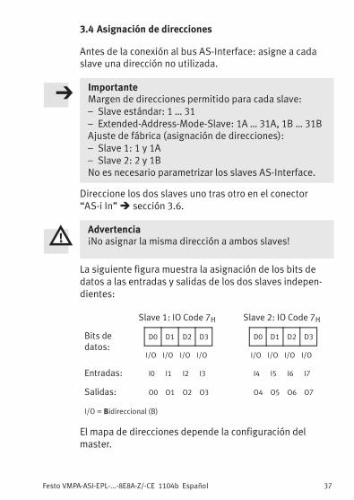
3.4 Asignación de direcciones
Antes de la conexión al bus AS-Interface: asigne a cadaslave una dirección no utilizada.
ImportanteMargen de direcciones permitido para cada slave:– Slave estándar: 1 … 31– Extended-Address-Mode-Slave: 1A … 31A, 1B … 31BAjuste de fábrica (asignación de direcciones):– Slave 1: 1 y 1A– Slave 2: 2 y 1BNo es necesario parametrizar los slaves AS-Interface.
Direccione los dos slaves uno tras otro en el conector“AS-i In”� sección 3.6.
Advertencia¡No asignar la misma dirección a ambos slaves!
La siguiente figura muestra la asignación de los bits dedatos a las entradas y salidas de los dos slaves indepen-dientes:
Slave 1: IO Code 7H Slave 2: IO Code 7H
Bits dedatos:
D0 D1 D2 D3 D0 D1 D2 D3
I/O I/O I/O I/O I/O I/O I/O I/O
Entradas: I0 I1 I2 I3 I4 I5 I6 I7
Salidas: O0 O1 O2 O3 O4 O5 O6 O7
I/O = Bidireccional (B)
El mapa de direcciones depende la configuración delmaster.
Festo VMPA-ASI-EPL-...-8E8A-Z/-CE 1104b Español38
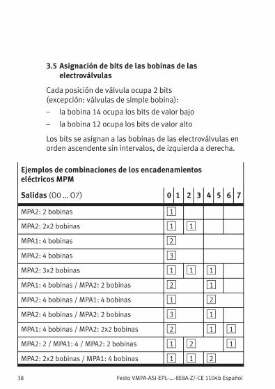
3.5 Asignación de bits de las bobinas de laselectroválvulas
Cada posición de válvula ocupa 2 bits(excepción: válvulas de simple bobina):
– la bobina 14 ocupa los bits de valor bajo
– la bobina 12 ocupa los bits de valor alto
Los bits se asignan a las bobinas de las electroválvulas enorden ascendente sin intervalos, de izquierda a derecha.
Ejemplos de combinaciones de los encadenamientoseléctricos MPM
Salidas (O0 … O7) 0 1 2 3 4 5 6 7
MPA2: 2 bobinas 1
MPA2: 2x2 bobinas 1 1
MPA1: 4 bobinas 2
MPA2: 4 bobinas 3
MPA2: 3x2 bobinas 1 1 1
MPA1: 4 bobinas / MPA2: 2 bobinas 2 1
MPA2: 4 bobinas / MPA1: 4 bobinas 1 2
MPA2: 4 bobinas / MPA2: 2 bobinas 3 1
MPA1: 4 bobinas / MPA2: 2x2 bobinas 2 1 1
MPA2: 2 / MPA1: 4 / MPA2: 2 bobinas 1 2 1
MPA2: 2x2 bobinas / MPA1: 4 bobinas 1 1 2
Festo VMPA-ASI-EPL-...-8E8A-Z/-CE 1104b Español 39
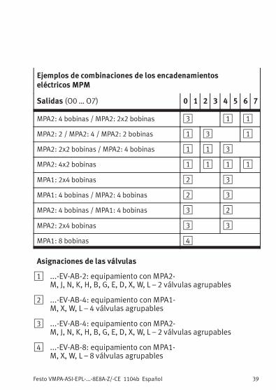
Ejemplos de combinaciones de los encadenamientoseléctricos MPM
Salidas (O0 … O7) 0 1 2 3 4 5 6 7
MPA2: 4 bobinas / MPA2: 2x2 bobinas 3 1 1
MPA2: 2 / MPA2: 4 / MPA2: 2 bobinas 1 3 1
MPA2: 2x2 bobinas / MPA2: 4 bobinas 1 1 3
MPA2: 4x2 bobinas 1 1 1 1
MPA1: 2x4 bobinas 2 3
MPA1: 4 bobinas / MPA2: 4 bobinas 2 3
MPA2: 4 bobinas / MPA1: 4 bobinas 3 2
MPA2: 2x4 bobinas 3 3
MPA1: 8 bobinas 4
Asignaciones de las válvulas
1 ...-EV-AB-2: equipamiento con MPA2-M, J, N, K, H, B, G, E, D, X, W, L – 2 válvulas agrupables
2 ...-EV-AB-4: equipamiento con MPA1-M, X, W, L – 4 válvulas agrupables
3 ...-EV-AB-4: equipamiento con MPA2-M, J, N, K, H, B, G, E, D, X, W, L – 2 válvulas agrupables
4 ...-EV-AB-8: equipamiento con MPA1-M, X, W, L – 8 válvulas agrupables
Festo VMPA-ASI-EPL-...-8E8A-Z/-CE 1104b Español40
3.6 Conexión del bus de AS-Interface y la tensión de carga
La alimentación a sensores para las entradas se realiza através del bus AS-Interface.
AdvertenciaUtilice solo fuentes de corriente eléctrica que garan-ticen un aislamiento eléctrico seguro de la tensión defuncionamiento según IEC/DIN EN 60204-1.Tenga en cuenta también los requisitos generales paracircuitos PELV según IEC/DIN EN 60204-1.
ImportanteLa alimentación de sensores obtenida a través de lafuente de alimentación de la interface AS estáprotegida frente cortocircuitos y sobrecargas.No debe conectarse con otros potenciales (p.ej. masacompartida).Las válvulas (salidas) siempre funcionan con alimen-tación adicional de 24 V, separada a través de laconexión de la tensión de carga.
Observar en caso de derivaciones intermedias:
– la longitud total máxima del bus AS-Interface(100 m sin repetidor/extendedor)
– la longitud del cable de tensión de carga (depende delconsumo de corriente y de las fluctuaciones en latensión de carga).
Festo VMPA-ASI-EPL-...-8E8A-Z/-CE 1104b Español 41
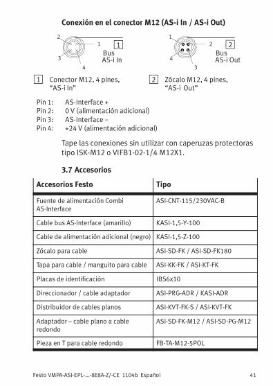
Conexión en el conector M12 (AS-i In / AS-i Out)
11
4
2
3BusAS-i In
22
3
1
4BusAS-i Out
1 Conector M12, 4 pines,“AS-i In”
2 Zócalo M12, 4 pines,“AS-i Out”
Pin 1: AS-Interface +Pin 2: 0 V (alimentación adicional)Pin 3: AS-Interface −Pin 4: +24 V (alimentación adicional)
Tape las conexiones sin utilizar con caperuzas protectorastipo ISK-M12 o VIFB1-02-1/4 M12X1.
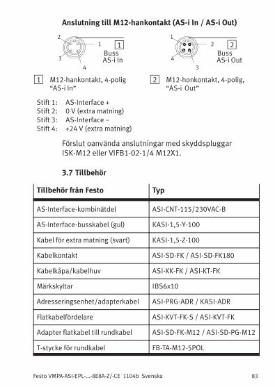
3.7 Accesorios
Accesorios Festo Tipo
Fuente de alimentación CombiAS-Interface
ASI-CNT-115/230VAC-B
Cable bus AS-Interface (amarillo) KASI-1,5-Y-100
Cable de alimentación adicional (negro) KASI-1,5-Z-100
Zócalo para cable ASI-SD-FK / ASI-SD-FK180
Tapa para cable / manguito para cable ASI-KK-FK / ASI-KT-FK
Distribuidor de cables planos ASI-KVT-FK-S / ASI-KVT-FK
Adaptador – cable plano a cableredondo
ASI-SD-FK-M12 / ASI-SD-PG-M12
Pieza en T para cable redondo FB-TA-M12-5POL
Festo VMPA-ASI-EPL-...-8E8A-Z/-CE 1104b Español42
4 Especificaciones técnicas
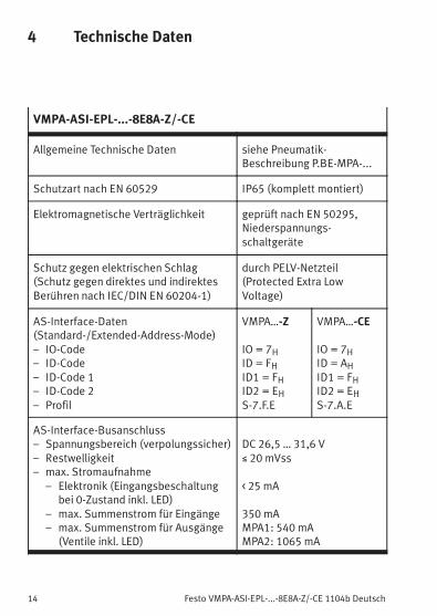
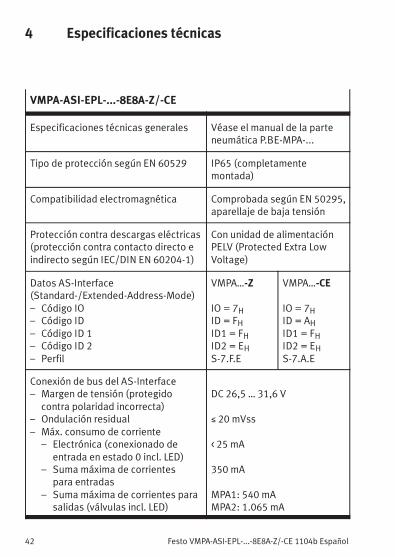
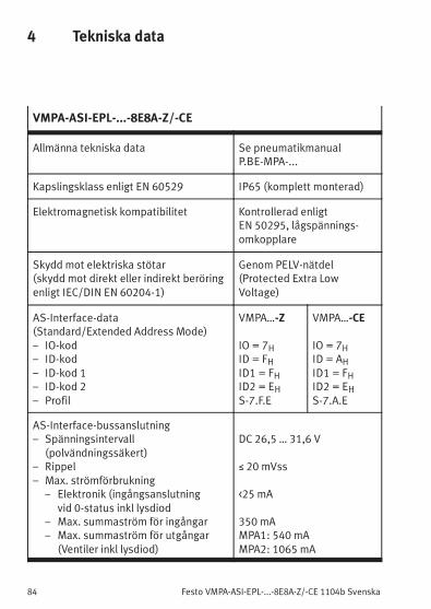
VMPA-ASI-EPL-...-8E8A-Z/-CE
Especificaciones técnicas generales Véase el manual de la parteneumática P.BE-MPA-...
Tipo de protección según EN 60529 IP65 (completamentemontada)
Compatibilidad electromagnética Comprobada según EN 50295,aparellaje de baja tensión
Protección contra descargas eléctricas(protección contra contacto directo eindirecto según IEC/DIN EN 60204-1)
Con unidad de alimentaciónPELV (Protected Extra LowVoltage)
Datos AS-Interface(Standard-/Extended-Address-Mode)– Código IO– Código ID– Código ID 1– Código ID 2– Perfil
VMPA…-Z
IO = 7HID = FHID1 = FHID2 = EHS-7.F.E
VMPA…-CE
IO = 7HID = AHID1 = FHID2 = EHS-7.A.E
Conexión de bus del AS-Interface– Margen de tensión (protegido
contra polaridad incorrecta)– Ondulación residual– Máx. consumo de corriente
– Electrónica (conexionado deentrada en estado 0 incl. LED)
– Suma máxima de corrientespara entradas
– Suma máxima de corrientes parasalidas (válvulas incl. LED)
DC 26,5 … 31,6 V
≤ 20 mVss
< 25 mA
350 mA
MPA1: 540 mAMPA2: 1.065 mA
Festo VMPA-ASI-EPL-...-8E8A-Z/-CE 1104b Español 43
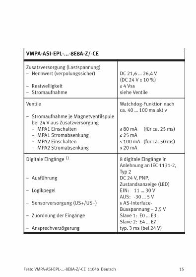
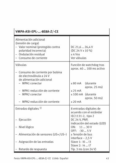
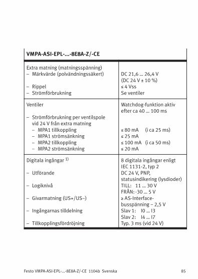
VMPA-ASI-EPL-...-8E8A-Z/-CE
Alimentación adicional(tensión de carga)– Valor nominal (protegido contra
polaridad incorrecta)– Ondulación residual– Consumo de corriente
DC 21,6 … 26,4 V(DC 24 V ± 10 %)≤ 4 VssVer válvulas
Válvulas
– Consumo de corriente por bobinade electroválvula a 24 Vde alimentación adicional– MPA1 conectar
– MPA1 reducción de corriente– MPA2 conectar
– MPA2 reducción de corriente
Función de watchdog trasaprox. 40 … 100 ms activo
≤ 80 mA (duranteaprox. 25 ms)
≤ 25 mA≤ 100 mA (durante
aprox. 50 ms)≤ 20 mA
Entradas digitales 1)
– Ejecución
– Nivel lógico
– Alimentación de sensores (US+/US−)
– Asignación de las entradas
– Retardo de respuesta
8 entradas digitales deacuerdo con el estándarIEC1131-2, tipo 2DC 24 V, PNP,indicación del estado (LED)ON: 11 … 30 VOFF: -30 … 5 V≥ Tensión de businterface − 2,5 VSlave 1: I0 … I3Slave 2: I4 … I7Típ. 3 ms (con 24 V)
Festo VMPA-ASI-EPL-...-8E8A-Z/-CE 1104b Español44
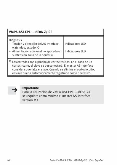
VMPA-ASI-EPL-...-8E8A-Z/-CE
Diagnosis– Tensión y dirección del AS-Interface,
watchdog, estado IO– Alimentación adicional no aplicada o
subtensión, fallo de la periferia
Indicadores LED
Indicadores LED
1) Las entradas son a prueba de cortocircuitos. En el caso de uncortocircuito, el slave se desconectará. El master AS-Interfaceconsidera que falta el slave. Cuando se elimina el cortocircuito,el slave queda automáticamente registrado como operativo.
ImportantePara la utilización de VMPA-ASI-EPL-...-8E8A-CEse requiere como mínimo el master AS-Interface,versión M3.
Festo VMPA-ASI-EPL-...-8E8A-Z/-CE 1104b Français 45
Français1 Instructions d’utilisation
Les terminaux de distributeurs de typeVMPA-ASI-EPL-...-8E8A-Z et VMPA-ASI-EPL-...-8E8A-CE sontexclusivement destinés à la commande d’actionneurspneumatiques sur le bus répondant aux
spécifications AS-Interface.
VMPA-ASI-EPL-...-8E8A-Z est utilisé en tant qu’esclavestandard tandis que VMPA-ASI-EPL-...-8E8A-CE est utilisé entant qu’esclave pour le mode “Extended Address”.
Les terminaux de distributeurs comportent 2 esclavesAS-Interface, appelés “esclave 1” et “esclave 2”. Ils secomportent sur le bus AS-Interface comme 2 terminaux dedistributeurs isolés avec chacun 4 entrées et sorties. Lesterminaux de distributeurs permettent ainsi le pilotage
de 4 bobines de distributeurs et la détection de 4 capteurs.Le raccordement des capteurs s’effectue à l’aide de la tech-nique de raccordement interchangeable du système CPX.
Lors du raccordement de composants supplémentaires
courants du commerce, respecter les valeurs limites depressions, de températures, de caractéristiques électriquesou de couples indiquées.
L’installation des bus AS-Interface et des terminaux dedistributeurs est réservée à un personnel qualifié et dûment
formé. Le manuel d’utilisation du maître AS-Interface fournitdes indications sur la conception et l’adressage du bus.
De plus amples informations concernant le systèmepneumatique du terminal de distributeurs se trouvent
dans le manuel Pneumatique de type P.BE-MPA-...
Avertissement� Couper l’alimentation avant de relier ou de séparerdes connecteurs à pousser (risques de dommagesfonctionnels).
� Mettre en service uniquement un terminal dedistributeurs entièrement monté et câblé.
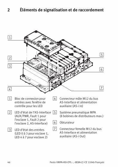
1 Bloc de connexion pourentrées avec fenêtre decontrôle pour les LED
2 LED d’état de l’AS-Interface(AUX/PWR, Fault 1 pourl’esclave 1, Fault 2 pourl’esclave 2, AS-Interface)
3 LED d’état des entrées(LED 0 à 3 pour esclave 1,LED 4 à 7 pour esclave 2)
4 Connecteur mâle M12 du busAS-Interface et alimentationauxiliaire (AS-i In)
5 Système pneumatique MPA(8 bobines de distributeurs max.)
6 Obturateur
7 Connecteur femelle M12 du busAS-Interface et alimentationauxiliaire (AS-i Out)
Festo VMPA-ASI-EPL-...-8E8A-Z/-CE 1104b Français 47
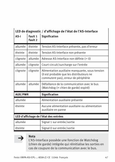
LED de diagnostic / d’affichage de l’état de l’AS-Interface
AS-i Fault 1Fault 2
Signification
allumée éteinte Tension AS-Interface présente, pas d’erreur
éteinte éteinte Tension AS-Interface non présente
clignote allumée Adresse AS-Interface non définie (= 0)
allumée clignote Court-circuit/surcharge sur l’entrée
clignote clignote Alimentation auxiliaire manquante, sous-tension(il est probable que les distributeurs necommutent pas), erreur de périphérie
allumée allumée Défaillance de la communication avec le bus(Watchdog (= chien de garde) expiré)
AUX/PWR Signification
allumée Alimentation auxiliaire présente
éteinte Aucune alimentation auxiliaire ou alimentationauxiliaire en panne
LED d’affichage de l’état des entrées
allumée Signal 1 sur entrée/sortie
éteinte Signal 0 sur entrée/sortie
NotaL’AS-Interface possède une fonction de Watchdog(chien de garde) intégrée qui réinitialise les sorties encas de coupure de la communication avec le bus.
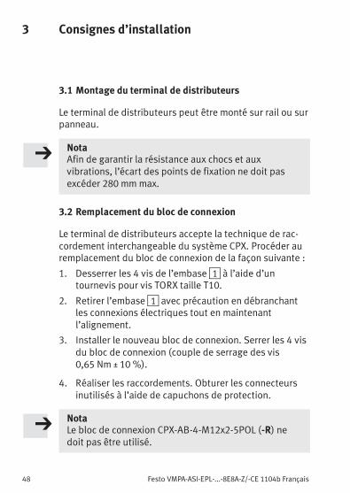
Le terminal de distributeurs peut être monté sur rail ou surpanneau.
NotaAfin de garantir la résistance aux chocs et auxvibrations, l’écart des points de fixation ne doit pasexcéder 280 mmmax.
3.2 Remplacement du bloc de connexion
Le terminal de distributeurs accepte la technique de rac-cordement interchangeable du système CPX. Procéder auremplacement du bloc de connexion de la façon suivante :
1. Desserrer les 4 vis de l’embase1 à l’aide d’untournevis pour vis TORX taille T10.
2. Retirer l’embase1 avec précaution en débranchantles connexions électriques tout en maintenantl’alignement.
3. Installer le nouveau bloc de connexion. Serrer les 4 visdu bloc de connexion (couple de serrage des vis0,65 Nm ± 10 %).
4. Réaliser les raccordements. Obturer les connecteursinutilisés à l’aide de capuchons de protection.
NotaLe bloc de connexion CPX-AB-4-M12x2-5POL (-R) nedoit pas être utilisé.
Festo VMPA-ASI-EPL-...-8E8A-Z/-CE 1104b Français 49
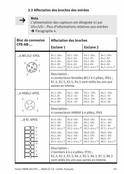
3.3 Affectation des broches des entrées
NotaL’alimentation des capteurs est désignée ici parUS+/US−. Plus d’informations relatives aux entrées� Paragraphe 4.
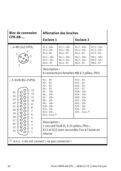
Bloc de connexionCPX-AB-...
Affectation des broches
Esclave 1 Esclave 2
...4-M12x2-5POL
2
3
1
5
4
X1.1 : US+
X1.2 : E1
X1.3 : US−
X1.4 : E0
X1.5 : d.n.c.1)
X2.1 : US+
X2.2 : E3
X2.3 : US−
X2.4 : E2
X2.5 : d.n.c.1)
X3.1 : US+
X3.2 : E5
X3.3 : US−
X3.4 : E4
X3.5 : d.n.c.1)
X4.1 :US+
X4.2 : E7
X4.3 :US−
X4.4 :E6
X4.5 : d.n.c.1)
Description :4 connecteurs femelles M12 à 5 pôles, IP65 ;X1.5, X2.5, X3.5, X4.5 sont reliés les uns auxautres en interne.
...4-HARx2-4POL
23
14
X1.1 : US+
X1.2 : E1
X1.3 : US−
X1.4 : E0
X2.1 : US+
X2.2 : E3
X2.3 : US−
X2.4 : E2
X3.1 : US+
X3.2 : E5
X3.3 : US−
X3.4 : E4
X4.1 : US+
X4.2 : E7
X4.3 : US−
X4.4 : E6
Description :4 connecteurs HARAX à 4 pôles, IP65
...8-KL-4POL
.0
.1
.2
.3
.0
.1
.2
.3
X1.0 : US+
X1.1 : US−
X1.2 : E0
X1.3 : d.n.c.1)
X2.0 : US+
X2.1 : US−
X2.2 : E1
X2.3 : d.n.c.1)
X3.0 : US+
X3.1 : US−
X3.2 : E1
X3.3 : d.n.c.1)
X4.0 :US+
X4.1 :US−
X4.2 : E3
X4.3 : d.n.c.1)
X5.0 : US+
X5.1 : US−
X5.2 : E4
X5.3 : d.n.c.1)
X6.0 : US+
X6.1 : US−
X6.2 : E5
X6.3 : d.n.c.1)
X7.0 : US+
X7.1 : US−
X7.2 : E6
X7.3 : d.n.c.1)
X8.0 : US+
X8.1 : US−
X8.2 : E7
X8.3 : d.n.c.1)
Description :2 borniers à 4 x 4 pôles, IP20 ;X1.3, X2.3, X3.3, X4.3, X5.3, X6.3, X7.3, X8.3sont reliés les uns aux autres en interne.
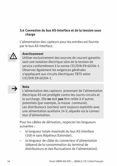
3.6 Connexion du bus AS-Interface et de la tension souscharge
L’alimentation des capteurs pour les entrées est fourniepar le bus AS-Interface.
AvertissementUtiliser exclusivement des sources de courant garantis-sant une isolation électrique sûre de la tension deservice conformément à la norme CEI/DIN EN 60204-1.Observez également les exigences généraless’appliquant aux circuits électriques TBTS selonCIE/DIN EN 60204-1.
NotaL’alimentation des capteurs provenant de l’alimentationélectrique AS est protégée contre les courts-circuits etla surcharge. Elle ne doit pas être reliée à d'autrespotentiels (par exemple, la masse commune).Les distributeurs (sorties) sont toujours exploités avecune alimentation auxiliaire 24 V, séparée via le connec-teur d’alimentation.
Pour les câbles de dérivation, respecter les longueurssuivantes :
– la longueur totale maximale du bus AS-Interface(100 m sans Répéteur/Extender).
– la longueur de câble du connecteur d’alimentation(dépend de la consommation du terminal dedistributeurs et des fluctuations de l’alimentation).
Festo VMPA-ASI-EPL-...-8E8A-Z/-CE 1104b Français 55
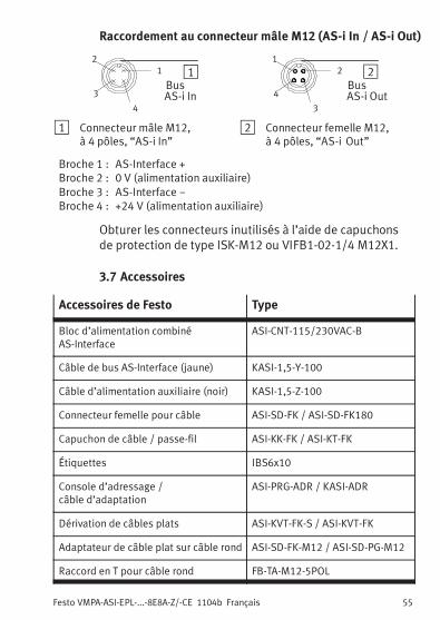
Raccordement au connecteur mâle M12 (AS-i In / AS-i Out)
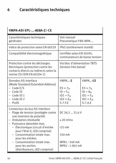
Indice de protection selon EN 60529 IP65 (entièrement monté)
Compatibilité électromagnétique Certifiée selon EN 50295,commutateurs de basse tension
Protection contre les déchargesélectriques (protection contre lescontacts directs ou indirects selon lanorme CEI/DIN EN 60204-1)
Via bloc d’alimentation TBTS(tension très basse)
Données AS-interface(Mode Standard/Extended-Address)– Code E/S– Code ID– Code ID 1– Code ID 2– Profil
VMPA…-Z
ES = 7HID = FHID1 = FHID2 = EHS-7.F.E
VMPA…-CE
ES = 7HID = AHID1 = FHID2 = EHS-7.A.E
Connecteur du bus AS-Interface– Plage de tension (protégée contre
une inversion de polarité)– Ondulation résiduelle– Puissance absorbée max.
– Électronique (circuit d’entréepour l’état 0, LED comprise)
– Consommation totale max.pour les entrées
– Consommation totale max.pour les sorties(distributeurs, LED comprise)
DC 26,5 … 31,6 V
≤ 20 mVss
<25 mA
350 mA
MPA1 : 540 mAMPA2 : 1 065 mA
Festo VMPA-ASI-EPL-...-8E8A-Z/-CE 1104b Français 57
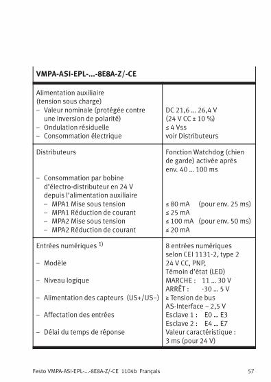
VMPA-ASI-EPL-...-8E8A-Z/-CE
Alimentation auxiliaire(tension sous charge)– Valeur nominale (protégée contre
une inversion de polarité)– Ondulation résiduelle– Consommation électrique
DC 21,6 … 26,4 V(24 V CC ± 10 %)≤ 4 Vssvoir Distributeurs
Distributeurs
– Consommation par bobined’électro-distributeur en 24 Vdepuis l’alimentation auxiliaire– MPA1 Mise sous tension– MPA1 Réduction de courant– MPA2 Mise sous tension– MPA2 Réduction de courant
Fonction Watchdog (chiende garde) activée aprèsenv. 40 … 100 ms
≤ 80 mA (pour env. 25 ms)≤ 25 mA≤ 100 mA (pour env. 50 ms)≤ 20 mA
Entrées numériques 1)
– Modèle
– Niveau logique
– Alimentation des capteurs (US+/US−)
– Affectation des entrées
– Délai du temps de réponse
8 entrées numériquesselon CEI 1131-2, type 224 V CC, PNP,Témoin d’état (LED)MARCHE : 11 … 30 VARRÊT : -30 … 5 V≥ Tension de busAS-Interface − 2,5 VEsclave 1 : E0 … E3Esclave 2 : E4 … E7Valeur caractéristique :3 ms (pour 24 V)
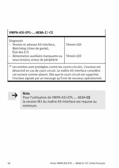
– Alimentation auxiliaire manquante ousous-tension, erreur de périphérie
Témoin LED
Témoin LED
1) Les entrées sont protégées contre les courts-circuits. L’esclave estdésactivé en cas de court-circuit. Le maître AS-Interface considèrecet esclave comme absent. Dès que le court-circuit est supprimé,l’esclave signale par un message qu’il est de nouveau opérationnel.
NotaPour l’utilisation de VMPA-ASI-EPL-...-8E8A-CEla version M3 du maître AS-Interface est requise auminimum.
Festo VMPA-ASI-EPL-...-8E8A-Z/-CE 1104b Italiano 59
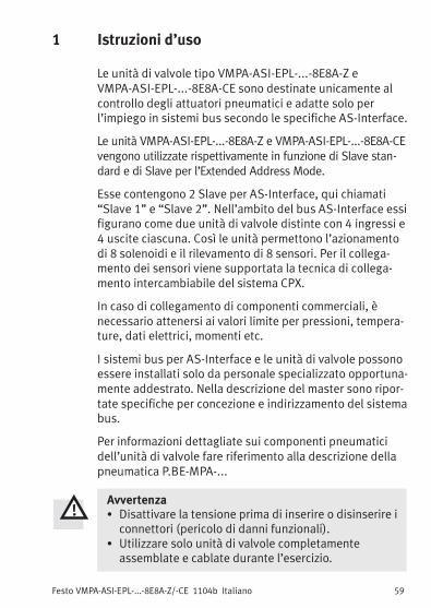
Italiano1 Istruzioni d’uso
Le unità di valvole tipo VMPA-ASI-EPL-...-8E8A-Z eVMPA-ASI-EPL-...-8E8A-CE sono destinate unicamente alcontrollo degli attuatori pneumatici e adatte solo perl’impiego in sistemi bus secondo le specifiche AS-Interface.
Le unità VMPA-ASI-EPL-...-8E8A-Z e VMPA-ASI-EPL-...-8E8A-CEvengono utilizzate rispettivamente in funzione di Slave stan-dard e di Slave per l’Extended Address Mode.
Esse contengono 2 Slave per AS-Interface, qui chiamati“Slave 1” e “Slave 2”. Nell’ambito del bus AS-Interface essifigurano come due unità di valvole distinte con 4 ingressi e4 uscite ciascuna. Così le unità permettono l’azionamentodi 8 solenoidi e il rilevamento di 8 sensori. Per il collega-mento dei sensori viene supportata la tecnica di collega-mento intercambiabile del sistema CPX.
In caso di collegamento di componenti commerciali, ènecessario attenersi ai valori limite per pressioni, tempera-ture, dati elettrici, momenti etc.
I sistemi bus per AS-Interface e le unità di valvole possonoessere installati solo da personale specializzato opportuna-mente addestrato. Nella descrizione del master sono ripor-tate specifiche per concezione e indirizzamento del sistemabus.
Per informazioni dettagliate sui componenti pneumaticidell’unità di valvole fare riferimento alla descrizione dellapneumatica P.BE-MPA-...
Avvertenza� Disattivare la tensione prima di inserire o disinserire iconnettori (pericolo di danni funzionali).
� Utilizzare solo unità di valvole completamenteassemblate e cablate durante l’esercizio.
L’unità di valvole può essere fissata su guida profilata oparete.
NotaPer garantire la resistenza a urti e vibrazioni, la distanzafra i punti di fissaggio non deve superare i 280 mm.
3.2 Sostituzione del blocco di collegamento
L’unità di valvole supporta la tecnica di collegamento inter-cambiabile del sistema CPX. Per sostituire il blocco dicollegamento, procedere nel modo seguente:
1. Allentare le 4 viti del blocco di collegamento1 con uncacciavite TORX, misura T10.
2. Procedendo con cautela, sfilare il blocco1 dai con-nettori elettrici senza inclinarlo.
3. Inserire un nuovo blocco. Stringere le 4 viti del blocco(coppia di serraggio delle viti 0,65 Nm ± 10 %).
4. Realizzare le connessioni. Chiudere le connessioni nonutilizzate con tappi di protezione.
NotaNon utilizzare il blocco di collegamentoCPX-AB-4-M12x2-5POL (-R).
Festo VMPA-ASI-EPL-...-8E8A-Z/-CE 1104b Italiano 63
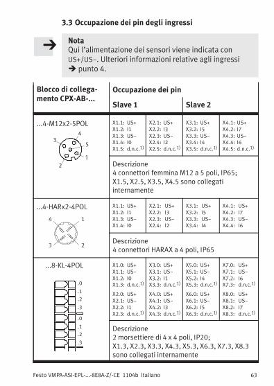
3.3 Occupazione dei pin degli ingressi
NotaQui l’alimentazione dei sensori viene indicata conUS+/US−. Ulteriori informazioni relative agli ingressi� punto 4.
Blocco di collega-mento CPX-AB-...
Occupazione dei pin
Slave 1 Slave 2
...4-M12x2-5POL
2
3
1
5
4
X1.1: US+
X1.2: I1
X1.3: US−
X1.4: I0
X1.5: d.n.c.1)
X2.1: US+
X2.2: I3
X2.3: US−
X2.4: I2
X2.5: d.n.c.1)
X3.1: US+
X3.2: I5
X3.3: US−
X3.4: I4
X3.5: d.n.c.1)
X4.1: US+
X4.2: I7
X4.3: US−
X4.4: I6
X4.5: d.n.c.1)
Descrizione4 connettori femmina M12 a 5 poli, IP65;X1.5, X2.5, X3.5, X4.5 sono collegatiinternamente
...4-HARx2-4POL
23
14
X1.1: US+
X1.2: I1
X1.3: US−
X1.4: I0
X2.1: US+
X2.2: I3
X2.3: US−
X2.4: I2
X3.1: US+
X3.2: I5
X3.3: US−
X3.4: I4
X4.1: US+
X4.2: I7
X4.3: US−
X4.4: I6
Descrizione4 connettori HARAX a 4 poli, IP65
...8-KL-4POL
.0
.1
.2
.3
.0
.1
.2
.3
X1.0: US+
X1.1: US−
X1.2: I0
X1.3: d.n.c.1)
X2.0: US+
X2.1: US−
X2.2: I1
X2.3: d.n.c.1)
X3.0: US+
X3.1: US−
X3.2: I1
X3.3: d.n.c.1)
X4.0: US+
X4.1: US−
X4.2: I3
X4.3: d.n.c.1)
X5.0: US+
X5.1: US−
X5.2: I4
X5.3: d.n.c.1)
X6.0: US+
X6.1: US−
X6.2: I5
X6.3: d.n.c.1)
X7.0: US+
X7.1: US−
X7.2: I6
X7.3: d.n.c.1)
X8.0: US+
X8.1: US−
X8.2: I7
X8.3: d.n.c.1)
Descrizione2 morsettiere di 4 x 4 poli, IP20;X1.3, X2.3, X3.3, X4.3, X5.3, X6.3, X7.3, X8.3sono collegati internamente
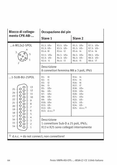
Descrizione1 connettore Sub-D a 25 poli, IP65;X13 e X25 sono collegati internamente
1) d.n.c. = do not connect; non connettere!
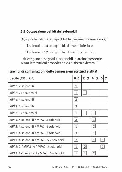
Festo VMPA-ASI-EPL-...-8E8A-Z/-CE 1104b Italiano 65
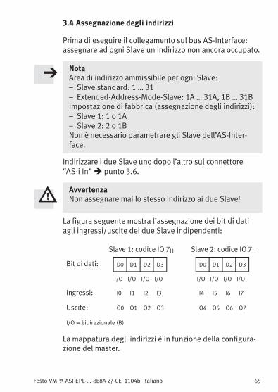
3.4 Assegnazione degli indirizzi
Prima di eseguire il collegamento sul bus AS-Interface:assegnare ad ogni Slave un indirizzo non ancora occupato.
NotaArea di indirizzo ammissibile per ogni Slave:– Slave standard: 1 … 31– Extended-Address-Mode-Slave: 1A … 31A, 1B … 31BImpostazione di fabbrica (assegnazione degli indirizzi):– Slave 1: 1 o 1A– Slave 2: 2 o 1BNon è necessario parametrare gli Slave dell’AS-Inter-face.
Indirizzare i due Slave uno dopo l’altro sul connettore“AS-i In”� punto 3.6.
AvvertenzaNon assegnare mai lo stesso indirizzo ai due Slave!
La figura seguente mostra l’assegnazione dei bit di datiagli ingressi/uscite dei due Slave indipendenti:
Slave 1: codice IO 7H Slave 2: codice IO 7H
Bit di dati: D0 D1 D2 D3 D0 D1 D2 D3
I/O I/O I/O I/O I/O I/O I/O I/O
Ingressi: I0 I1 I2 I3 I4 I5 I6 I7
Uscite: O0 O1 O2 O3 O4 O5 O6 O7
I/O = bidirezionale (B)
La mappatura degli indirizzi è in funzione della configura-zione del master.
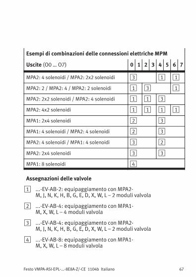
3.6 Collegare bus AS-Interface e tensione di carico
L’alimentazione dei sensori per gli ingressi viene appron-tata tramite il bus dell’AS-Interface.
AvvertenzaUtilizzare solo sorgenti di energia in grado di garantireun isolamento elettrico sicuro della tensione d’eserciziosecondo IEC/DIN EN60204-1.Inoltre osservare i requisiti generali per i circuitielettrici PELV previsti dalle norme IEC/DIN EN 60204-1.
NotaL’alimentazione dei sensori ottenuta dall’alimenta-zione elettrica per AS-Interface è protetta controcortocircuiti e sovraccarichi. Non deve essere collegataad altri potenziali (ad es. massa comune).Le valvole (uscite) vengono azionate sempre conalimentazione supplementare di 24 V, separatamentetramite l’attacco della tensione di carico.
Per le linee derivate osservare:
– la lunghezza max. totale del bus AS-Interface(100 m senza Repeater/Extender)
– la lunghezza della linea dell’attacco della tensione dicarico (in funzione dell’assorbimento di correntedell’unità di valvole e delle variazioni della tensione dicarico)
Festo VMPA-ASI-EPL-...-8E8A-Z/-CE 1104b Italiano 69
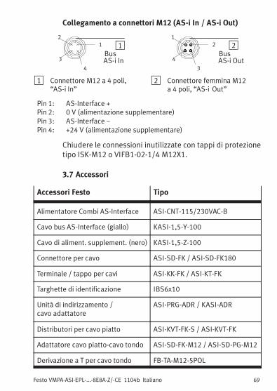
Collegamento a connettori M12 (AS-i In / AS-i Out)
11
4
2
3BusAS-i In
22
3
1
4BusAS-i Out
1 Connettore M12 a 4 poli,“AS-i In”
2 Connettore femmina M12a 4 poli, “AS-i Out”
Pin 1: AS-Interface +Pin 2: 0 V (alimentazione supplementare)Pin 3: AS-Interface −Pin 4: +24 V (alimentazione supplementare)
Chiudere le connessioni inutilizzate con tappi di protezionetipo ISK-M12 o VIFB1-02-1/4 M12X1.
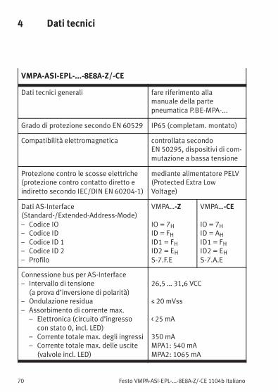
Dati tecnici generali fare riferimento allamanuale della partepneumatica P.BE-MPA-...
Grado di protezione secondo EN 60529 IP65 (completam. montato)
Compatibilità elettromagnetica controllata secondoEN 50295, dispositivi di com-mutazione a bassa tensione
Protezione contro le scosse elettriche(protezione contro contatto diretto eindiretto secondo IEC/DIN EN 60204-1)
mediante alimentatore PELV(Protected Extra LowVoltage)
Dati AS-Interface(Standard-/Extended-Address-Mode)– Codice IO– Codice ID– Codice ID 1– Codice ID 2– Profilo
VMPA…-Z
IO = 7HID = FHID1 = FHID2 = EHS-7.F.E
VMPA…-CE
IO = 7HID = AHID1 = FHID2 = EHS-7.A.E
Connessione bus per AS-Interface– Intervallo di tensione
(a prova d’inversione di polarità)– Ondulazione residua– Assorbimento di corrente max.
– Elettronica (circuito d’ingressocon stato 0, incl. LED)
– Corrente totale max. degli ingressi– Corrente totale max. delle uscite
(valvole incl. LED)
26,5 … 31,6 VCC
≤ 20 mVss
< 25 mA
350 mAMPA1: 540 mAMPA2: 1065 mA
Festo VMPA-ASI-EPL-...-8E8A-Z/-CE 1104b Italiano 71
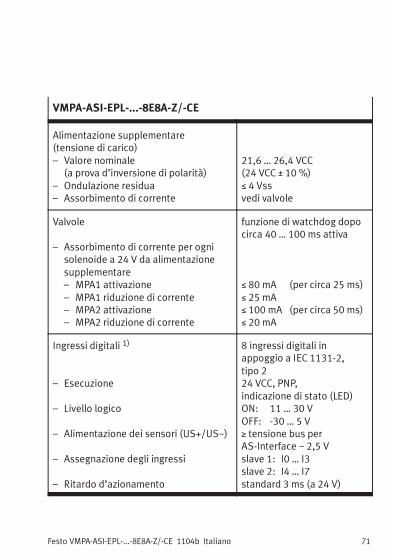
VMPA-ASI-EPL-...-8E8A-Z/-CE
Alimentazione supplementare(tensione di carico)– Valore nominale
(a prova d’inversione di polarità)– Ondulazione residua– Assorbimento di corrente
21,6 … 26,4 VCC(24 VCC ± 10 %)≤ 4 Vssvedi valvole
Valvole
– Assorbimento di corrente per ognisolenoide a 24 V da alimentazionesupplementare– MPA1 attivazione– MPA1 riduzione di corrente– MPA2 attivazione– MPA2 riduzione di corrente
funzione di watchdog dopocirca 40 … 100 ms attiva
≤ 80 mA (per circa 25 ms)≤ 25 mA≤ 100 mA (per circa 50 ms)≤ 20 mA
Ingressi digitali 1)
– Esecuzione
– Livello logico
– Alimentazione dei sensori (US+/US−)
– Assegnazione degli ingressi
– Ritardo d’azionamento
8 ingressi digitali inappoggio a IEC 1131-2,tipo 224 VCC, PNP,indicazione di stato (LED)ON: 11 … 30 VOFF: -30 … 5 V≥ tensione bus perAS-Interface − 2,5 Vslave 1: I0 … I3slave 2: I4 … I7standard 3 ms (a 24 V)
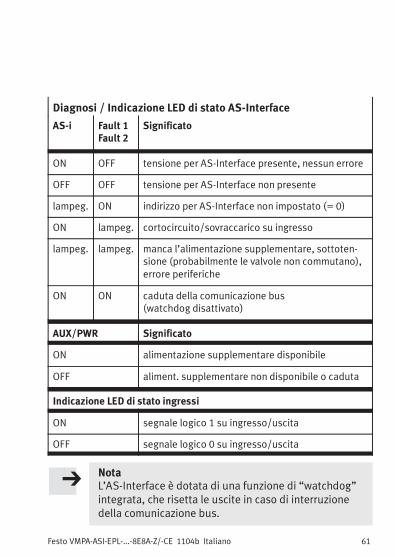
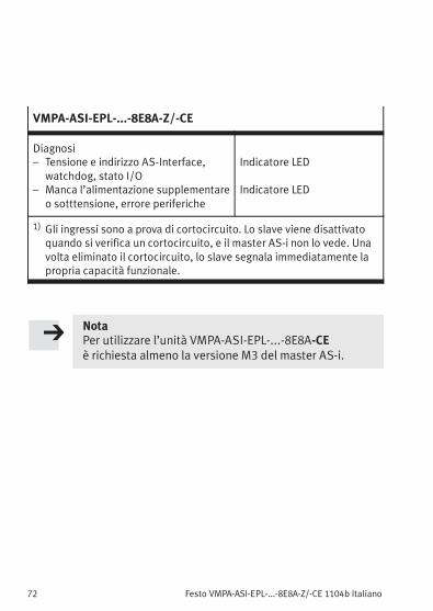
watchdog, stato I/O– Manca l’alimentazione supplementare
o sotttensione, errore periferiche
Indicatore LED
Indicatore LED
1) Gli ingressi sono a prova di cortocircuito. Lo slave viene disattivatoquando si verifica un cortocircuito, e il master AS-i non lo vede. Unavolta eliminato il cortocircuito, lo slave segnala immediatamente lapropria capacità funzionale.
NotaPer utilizzare l’unità VMPA-ASI-EPL-...-8E8A-CEè richiesta almeno la versione M3 del master AS-i.
Festo VMPA-ASI-EPL-...-8E8A-Z/-CE 1104b Svenska 73
Svenska1 Användaranvisningar
Ventilterminal VMPA-ASI-EPL-...-8E8A-Z ochVMPA-ASI-EPL-...-8E8A-CE är endast avsedd för styrning avpneumatiska arbetselement och enbart för användning ibussystem enligt AS-Interface-specifikationer.
VMPA-ASI-EPL-...-8E8A-Z används som standardslav ochVMPA-ASI-EPL-...-8E8A-CE används som slav för ExtendedAddress Mode.
Ventilterminalen innehåller 2 AS-Interface-slavar, som härbetecknas som “slav 1” och “slav 2”. Terminalen fungerar påAS-Interface-bussen som 2 enskilda ventilterminaler medvardera 4 in- och utgångar. Ventilterminalen tillåter styrningav 8 ventilspolar och avläsning av 8 givare. För anslutningav givarna stöder ventilterminalen CPX-systemets utbytbaraanslutningsteknik.
Vid anslutning av i handeln förekommandetillsatskomponenter, ska angivna gränsvärden för tryck,temperaturer, elektriska data, moment etc. följas.
AS-Interface-bussystem och ventilterminaler får endastinstalleras av behörig personal. Uppgifter för installationoch adressering av aktuellt bussystem finns i manualen tilldin AS-Interface-master.
Utförlig information om ventilterminalens pneumatik finns ipneumatikmanualen P.BE-MPA-...
Varning� Koppla från spänningen innan kontakter ansluts ellerlossas (risk för funktionsskada).
� Ta endast en komplett monterad och anslutenventilterminal i drift.
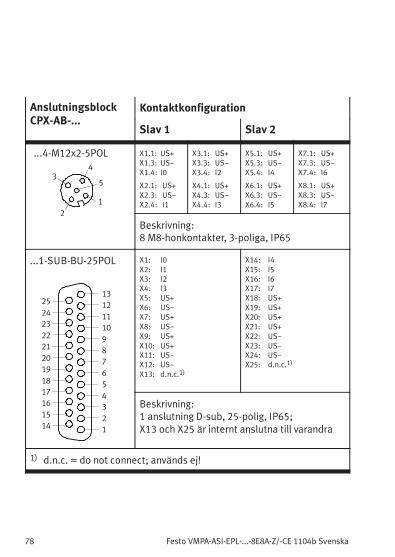
Beskrivning:1 anslutning D-sub, 25-polig, IP65;X13 och X25 är internt anslutna till varandra
1) d.n.c. = do not connect; används ej!
Festo VMPA-ASI-EPL-...-8E8A-Z/-CE 1104b Svenska 79
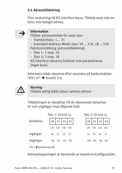
3.4 Adresstilldelning
Före anslutning till AS-Interface-buss: Tilldela varje slav enännu inte belagd adress.
InformationTillåtet adressområde för varje slav:– Standardslav: 1 … 31– Extended-Address-Mode-slav: 1A … 31A, 1B … 31BFabriksinställning (adresstilldelning):– Slav 1: 1 resp. 1A– Slav 2: 2 resp. 1BAS-Interface-slavarna behöver inte parametreras(inget krav).
Adressera båda slavarna efter varandra på hankontakten“AS-i In”� Avsnitt 3.6.
VarningTilldela aldrig båda slavar samma adress!
Tilldelningen av databitar till de oberoende slavarnasin- och utgångar visar följande bild:
Slav 1: IO-kod 7H Slav 2: IO-kod 7H
Databitar: D0 D1 D2 D3 D0 D1 D2 D3
I/O I/O I/O I/O I/O I/O I/O I/O
Ingångar: I0 I1 I2 I3 I4 I5 I6 I7
Utgångar: O0 O1 O2 O3 O4 O5 O6 O7
I/O = Bidirektionell (B)
Adressmappningen är beroende av masterns konfiguration.
Festo VMPA-ASI-EPL-...-8E8A-Z/-CE 1104b Svenska80
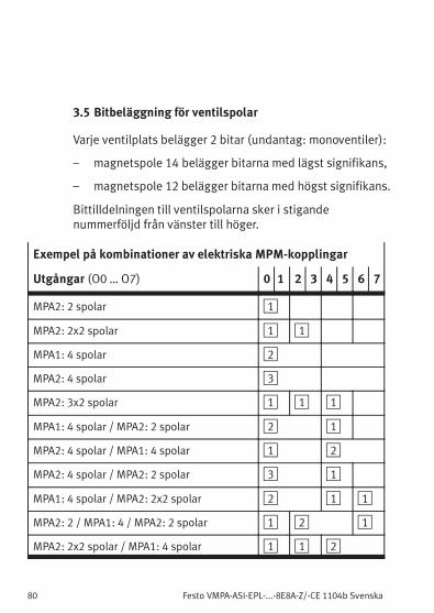
3.5 Bitbeläggning för ventilspolar
Varje ventilplats belägger 2 bitar (undantag: monoventiler):
– magnetspole 14 belägger bitarna med lägst signifikans,
– magnetspole 12 belägger bitarna med högst signifikans.
Bittilldelningen till ventilspolarna sker i stigandenummerföljd från vänster till höger.
Exempel på kombinationer av elektriska MPM-kopplingar
Utgångar (O0 … O7) 0 1 2 3 4 5 6 7
MPA2: 2 spolar 1
MPA2: 2x2 spolar 1 1
MPA1: 4 spolar 2
MPA2: 4 spolar 3
MPA2: 3x2 spolar 1 1 1
MPA1: 4 spolar / MPA2: 2 spolar 2 1
MPA2: 4 spolar / MPA1: 4 spolar 1 2
MPA2: 4 spolar / MPA2: 2 spolar 3 1
MPA1: 4 spolar / MPA2: 2x2 spolar 2 1 1
MPA2: 2 / MPA1: 4 / MPA2: 2 spolar 1 2 1
MPA2: 2x2 spolar / MPA1: 4 spolar 1 1 2
Festo VMPA-ASI-EPL-...-8E8A-Z/-CE 1104b Svenska 81
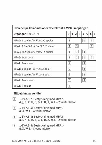
Exempel på kombinationer av elektriska MPM-kopplingar
Utgångar (O0 … O7) 0 1 2 3 4 5 6 7
MPA2: 4 spolar / MPA2: 2x2 spolar 3 1 1
MPA2: 2 / MPA2: 4 / MPA2: 2 spolar 1 3 1
MPA2: 2x2 spolar / MPA2: 4 spolar 1 1 3
MPA2: 4x2 spolar 1 1 1 1
MPA1: 2x4 spolar 2 3
MPA1: 4 spolar / MPA2: 4 spolar 2 3
MPA2: 4 spolar / MPA1: 4 spolar 3 2
MPA2: 2x4 spolar 3 3
MPA1: 8 spolar 4
Tilldelning av ventiler
1 ...-EV-AB-2: Bestyckning med MPA2-M, J, N, K, H, B, G, E, D, X, W, L – 2 ventilplattor
2 ...-EV-AB-4: Bestyckning med MPA1-M, X, W, L – 4 ventilplattor
3 ...-EV-AB-4: Bestyckning med MPA2-M, J, N, K, H, B, G, E, D, X, W, L – 2 ventilplattor
4 ...-EV-AB-8: Bestyckning med MPA1-M, X, W, L – 8 ventilplattor
Festo VMPA-ASI-EPL-...-8E8A-Z/-CE 1104b Svenska82
3.6 Ansluta AS-Interface-buss och matningsspänning
Via AS-Interface-bussen förses ingångarna medgivarmatning.
VarningAnvänd endast strömkällor som garanterar ensäker isolering av matningsspänningen enligtIEC/DIN EN 60204-1.Följ dessutom allmänna krav på PELV-kretsar enligtIEC/DIN EN 60204-1.
InformationGivarmatningen, som tas via AS-Interface-spännings-försörjningen, är skyddad mot kortslutning och över-belastning. Den får inte anslutas till annan potential(t ex gemensam jord).Ventilerna (utgångarna) används alltid med extra mat-ning 24 V, separat via matningsspänningens anslutning.
Observera följande vid förgreningar:
– Max. totallängd för AS-Interface-buss(100 m utan repeater/extender)
– Kabellängden för matningsspänningens anslutning(beroende på ventilterminalens strömförbrukning ochsvängningar i matningsspänningen).
Festo VMPA-ASI-EPL-...-8E8A-Z/-CE 1104b Svenska 83
Anslutning till M12-hankontakt (AS-i In / AS-i Out)
11
4
2
3BussAS-i In
22
3
1
4BussAS-i Out
1 M12-hankontakt, 4-polig“AS-i In”
2 M12-honkontakt, 4-polig,“AS-i Out”
Stift 1: AS-Interface +Stift 2: 0 V (extra matning)Stift 3: AS-Interface −Stift 4: +24 V (extra matning)
Förslut oanvända anslutningar med skyddspluggarISK-M12 eller VIFB1-02-1/4 M12X1.
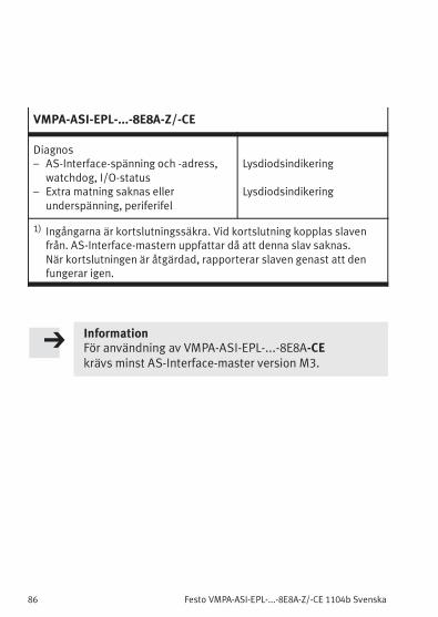
1) Ingångarna är kortslutningssäkra. Vid kortslutning kopplas slavenfrån. AS-Interface-mastern uppfattar då att denna slav saknas.När kortslutningen är åtgärdad, rapporterar slaven genast att denfungerar igen.
InformationFör användning av VMPA-ASI-EPL-...-8E8A-CEkrävs minst AS-Interface-master version M3.