By experience solar thermal systems are facing a lot of problems caused by gas enclosed in the hydraulic circuits (cavities or gas cushion). Problems known so far are flow instabilities as well as significant degradation of system efficiency. Even damage of system components has been observed. An important and extensive part of the commissioning is the filling procedure with the aim of minimal enclosing of gas. The installation of additional components like air vents shall lower the amount of gas during and after the filling procedure. For bigger fields degassing units are often necessary. The effectiveness of these strategies (and additional components) has not been evaluated until now. Therefore the main objectives of research are (a) to characterize the conditions that cause the formation of enclosed
816 Karin Rühling et al. / Energy Procedia 30 ( 2012 ) 815 – 823
gases and (b) to find outaa optimized venting and degasification strategies to be applied in typical solarthermal installations. Consequently the following three tasks have to be solved:
1. Determination of solubility coefficients for solar liquids (water-propylene-glycol-mixtures with inhibitors),
2. Testing the performance of venting and degasification equipment (state of the art for productsavailable on the market) based on qualified test-rig-investigations,
3. Validation of the results in real solar-thermal circuits.
2. Determination of solubility coefficients for solar liquids / water-glycol-mixtures
Mostly nitrogen and oxygen are gases dissolved in liquid circuits. Oxygen is consumed during oxidation as corrosion of metallic materials, partially assisted by inhibitors of the mixture. The inert gasnitrogen remains in the system. The mtt aximum dissolvable amount of nitrogen max,2Nx depends on
temperature, pressure and the type of liquid (solvent S)SS . For a small amount of gas (i.e. low partialpressure) the maximum solubility in state of equilibrium can be described by t HENRY´s law, Equation (1).
22
2,,22,2
max,2 )()(
1)( NN
SNNSNN
SNN p
M N
M STpTH
TxH N2N
(1)
For steady state temperatures the maximum concentration of dissolved nitrogen )(max,2 TcN is proportional to the partial pressure 2Np as given by Equation (2).
22,,2max,2 )()()( NSNNSNN pTTTc p(SNN (2(( )2
The factors are: )(TS (S (density of the solvent), 2,NN ,N (standard density of gas) and the temperature-dependent technical solubility coefficient )(,2 TSNN , which describes the solubility of nitrogen in the solvent S at temperatureT .
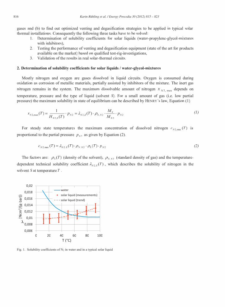
Fig. 1. Solubility coefficients of N2 in water and in a typical solar liquid
Karin Rühling et al. / Energy Procedia 30 ( 2012 ) 815 – 823 817
Both technical solubility coefficient )(2,2 TOHN and corresponding HENRY coefficients )(20,2 TH HN of nitrogen in the solvent water are well
known [2, 3]: For temperature less than 90 °C the technical solubility coefficient decreases as temperature increases (Fehler! Verweisquelle konnte nicht gefunden werden.).
The dependency of the solubility coefficient on pressure can be neglected if the system pressure is in the range of 0 to 30 bar, which means that the given relation is sufficient for technical applications.
For solar liquids solubility coefficients are not yet known. Therefore an experimental test rig has been
developed to allow the identification of coefficients in dependency on temperature. The setup of the experiment is based on a volumetric-manometric measuring method along with an
isochoric thermodynamic process. The test rig consists of two tempered volumes: the gas reservoir and the reactor. The reactor includes the solvent with a gas phase above it and is in equilibrium state. A defined amount of pure gas is moved from the more pressurized reservoir to the reactor, which increases the partial pressure 2Np in the reactor.
Gasflasche
Druckregler
V1
P
Gasreservoir Reaktor
W
V2
V3
Vakuumpumpe
PT
T
Thermostat
T
Reaktor
pressure control unit
gas cylindergas reservoir reactor
thermostat
vacuum pump
Fig. 2. left: test rig setting; right: experimental setup scheme
In the reactor the gas is partly dissolved in the liquid through absorption until a state of equilibrium is achieved. By measuring the pressure difference between the two states in the reactor the amount of dissolved gas and finally the solubility coefficients )(,2 TSN can be derived. Due to the small quantities of absorbed gas, the apparatus is very sensitive for measurement errors. Thus, both a complex analysis of measurement uncertainties and an optimization of the measurement method are necessary. For that reason the apparatus was calibrated with water. This will also help to guarantee reliable results and a reduction of bias. After calibration a typical solar liquid Tyfocor® LS (water-propylene-glycol-mixture with inhibitors) was investigated. Fehler! Verweisquelle konnte nicht gefunden werden. shows the solubility coefficients of this solar liquid. For technical applications it is possible to calculate with Eq. (3), valid from 10 to 95 °C.
818 Karin Rühling et al. / Energy Procedia 30 ( 2012 ) 815 – 823
2210,2 tataaLSN (3)
)/(107.3
)/(101.2
)/(0096.0
2372
361
30
CbargNcma
CbargNcma
bargNcma
The clear and significant differences of the solar liquid Tyfocor® LS compared to water will have an impact on venting and degasification.
So called HENRY-diagrams are helpful for practical purposes. These plots represent the limits of maximum solubility for several temperatures as a function of total pressure p for given state of equilibrium between gas and liquid. The total pressure includes the partial pressures of the gas components and in respect to the RAOULT-law the temperature dependent boiling pressure pB,S (T) of the solvent. Eq. (4) describes the total pressure p in the state of equilibrium with air atmosphere simplified with pres representing the residual gases. For ideal gases this can be expressed as shown on the right side with yi for the mole fraction of the gases in dry air.
From Eq. (4) it can also be deduced that the gas solubility at the boiling point of the liquid is assumed to be zero. The Henry-diagrams (Fig. 3) clearly shows the different position of the equilibrium lines for water and the solar fluid concerning the inert gas nitrogen (yN2 = 0.7805). For all isotherms dissolved gas is only possible for total pressures above vapor pressure of the liquid. The isotherms of water and Tyfocor® LS cross the x-axis at almost identical points at only slightly different boiling pressures while the slope of the isotherms of maximum solubility for several temperatures differs significantly. The slope of the isotherms of maximum solubility for several temperatures differs significantly. Isotherms for water fan out slightly and Tyfocor® LS-lines intersect. In the observed temperature range the amount of dissolved nitrogen declines with an increasing temperature for the solvent water. On the other hand there is a maximum amount of dissolved nitrogen for p > 0.5 barg and temperatures from 50 to 70 °C for Tyfocor® LS.
Fig. 3. HENRY-diagram for nitrogen in state of equilibrium with air atmosphere for 10 °C < t < 110 °C left: solvent water; right: solvent Tyfocor® LS
Karin Rühling et al. / Energy Procedia 30 ( 2012 ) 815 – 823 819
3. Experimental studies on operational venting and degasification
The experimental setup of the indoor test rig contains an artificial sun (halogen bulb field) illuminating three standard flat-plate collectors, a transportable solar station with the pressure maintenance and a continually rising pipe installation.
Several automatic air vents (3 no.), micro bubble separators (5 no.), and vacuum degasificationsystems (3 no.) can be included optionally in different locations. It is possible to connect the transportablesolar station at static heights of either 1.2, 5.0, or 9.3 meter.
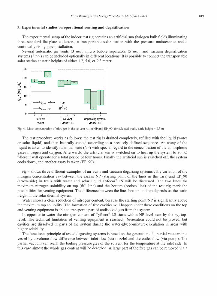
Fig. 4. Mass concentration of nitrogen in the solvent cN2 in NP and EP_90 for selected trials, static height = 9,3 m
The test procedure works as follows: the test rig is drained completely, refilled with the liquid (water or solar liquid) and then basically vented according to a precisely defined sequence. An assay of theliquid is taken to identify its initial state (NP) with special regard to the concentration of the atmosphericgases nitrogen and oxygen. Afterwards, the artificial sun is switched on to heat up the system to 90 °Cwhere it will operate for a total period of four hours. Finally the artificial sun is switched off, the systemcools down, and another assay is taken (EP_90).
Fig. 4 shows three different examples of air vents and vacuum degassing systems .The variation of thenitrogen concentration cN2 between the assays NP (starting point of the lines in the bars) and EP_90(arrow-side) in trails with water and solar liquid Tyfocor® LS will be discussed. The two lines formaximum nitrogen solubility on top (full line) and the bottom (broken line) of the test rig mark thepossibilities for venting equipment. The difference between the lines bottom and top depends on the staticheight in the solar thermal system.
Water shows a clear reduction of nitrogen content, because the starting point NP is signifcantly abovethe maximum top solubility. The formation of free cavities will happen under these conditions on the topand venting equipment is able to transport a part of undisolved gas from the system.
In opposite to water the nitrogen content of Tyfocor® LS starts with a NP-level near by the cN2-top-level. The technical limitation of venting equipment is reached. De-aeration could not be proved, butcavities are dissolved in parts of the system during the water-glycol-mixture-circulation in areas withhigher solubility.
The functional principle of tested degassing systems is based on the generation of a partial vacuum in a vessel by a volume flow difference between inlet flow (via nozzle) and the outlet flow (via pump). The partial vacuum can reach the boiling pressure pB,SB of the solvent for the temperature at the inlet side. Inthis case almost the whole gas content will be desorbed. A large part of the free gas can be removed via a
820 Karin Rühling et al. / Energy Procedia 30 ( 2012 ) 815 – 823
special air vent. The operation of the degasification systems could reduce the N2NN -concentrationaa reliably toabout 5 mgN2/lS.
Fig. 5. HENRY-diagram for the maximum mass concentration of nitrogen in the solar liquid cN2,max over the system pressure p(assumption: humid air in the gas phase)
Fig. 5 shows a HENRY-diagram that relates the nitrogen solubiu lity in the solar liquid to both the actualtemperature and the pressure conditions observed at the laboratory test rig. The HENRY-diagram reveals the maximum concentration of dissolved nitrogen cN2,max in terms of constant temperature over the system pressure p. The concentration cN2,max is plotted for the top and bottom of the solar circuit, as well as themeasured nitrogen concentration both of the assay NP and EP_90. It can be seen that it is not possible todissolve all nitrogen detected in the EP_90 assay at the top of the solar circuit. Undissolved nitrogencould not be led out through the vent during the experiment.
4. In-situ measurements of solar thermal systems
Indoor test rig experiments have been run under conditions close to reality (e. g. installation, fillingmethod, design of pressure maintenance). So test rig experiences should be compared with in-situ measurement results in real installations that are typical for medium to big sized solar systems. Sevensystems with installed solar collector areas in the range of 80 to 140 m² and geodetic height differences upto 23 m could be investigated in 2011.
It was necessary to develop a mobile measurement equipment to extract unaltered assays of the solar liquid from the solar circuits. For that reason a closed circuit had to be installed to avoid that ambient airgets in contact with the liquid while extracting the assay (Fig. 6). Nevertheless the measurement method ttallows only detecting liquid 30 °C, maximum concentration of dissolved nitrogen is cN2,max = 12 mgN2/lS. That means, 10 mgN2/lS will be desorbed from the liquid when circulating from the bottom to the top of the system. Desorbed gases again will form cavities or gas cushions at the top of the circuit. Six of theseven inspected solar systems contained undissolved nitrogen to a degree that allows for the assumptionof decreased solar heat gain due to inefficient solar circuits.properties at the specific point of sampling.Liquid properties especially gas content may differ along the system. It is also important to consider thatin addition to dissolved nitrogen gas cushions can exist in the system, which are more or less fixed and
Karin Rühling et al. / Energy Procedia 30 ( 2012 ) 815 – 823 821
not transported with the liquid. Measurement results for nitrogen content cN2 observed in-situ are in a range of 20 to 32 mgN2/lS.
Evaluation of these results requires a specific analysis for each installation using the HENRY-law as shown in Fig. 6. The N2-value of 22 mgN2/lS is a boundary line between critical (undissolved nitrogen) and noncritical area. Considering the conditions at the top of the circuit with ptop = 1.3 bar and ttop = 30 °C, maximum concentration of dissolved nitrogen is cN2,max = 12 mgN2/lS. That means, 10 mgN2/lS will be desorbed from the liquid when circulating from the bottom to the top of the system. Desorbed gases again will form cavities or gas cushions at the top of the circuit. Six of the seven inspected solar systems contained undissolved nitrogen to a degree that allows for the assumption of decreased solar heat gain due to inefficient solar circuits.
0
10
20
30
40
50
60
70
80
0 1 2 3 4 5
CN
2,m
ax(m
g N
2/k
g L
S)
p (bar)
10 °C
30 °C
50 °C
70 °C
90 °C
110 °C
measurement result
10 °C
70 °C
110 °C
bott
om
pre
ssure
30 °C
uncriticalcritical
top
pre
ssure
Fig. 6. left: HENRY diagram - Example for measurement results; right: in-situ measurement device at the bottom of the system
The results for oxygen content are between 0.03 and 0.08 mgO2/lS for systems with membrane expansion vessels and lies in the normal range up to 0.1 mgO2/lS. Three circuits with compressor-based pressure maintenance systems showed a considerable increase in oxygen concentration (2.7 to 3.9 mgO2/lS) and therefore an increased risk of corrosion.
5. Conclusion and future prospects
Within the project a laboratory test rig for the determination of solubility coefficients for solar liquids has been designed and constructed. For the first time this device allows the determination of solubility coefficients )(,2 tLSN for Tyfocor® LS in the temperature range of 10 °C t 110 °C.
From theoretical and empirical studies it can be also concluded that:
Solar liquids can solve a lower amount of nitrogen than water does.
There is no formation of micro-cavities in case of heating up solar liquids to 90 °C. This is the reason for the malfunction of air vents and micro bubble separators.
822 Karin Rühling et al. / Energy Procedia 30 ( 2012 ) 815 – 823
The degasification units investigated in the project worked reliably for both water and water-glycol-mixture.
Incorrect sizing and installation of pressure maintenance systems determine problems with undissolved (mainly nitrogen) and dissolved (mainly oxygen) gases in solar-thermal circuits.
The aims of further investigations are:
Qualitative and quantitative detection of cavities and gas cautions,
Optimized filling procedures for installations with huge static heights and
Recommendations for operation of degasification units for medium and big sized solar-thermal systems.
In the context of further improvement of solar-thermal systems the degasification and solubility of gases in solar liquids needs to be taken into account in a more serious way. Otherwise solar thermal systems will often be operating at inefficient conditions with additional risk of system injuries mainly due to gas cavities and corrosion.
Nomenclature cN2 mass concentration of the dissolved gas (mgN2/lS)
SNH ,2 HENRY-coefficient for nitrogen in solvent S (bar molS/molN2)
LS Tyfocor® LS (water-propylene-glycol-mixture with inhibitors)
M molar mass
p total pressure (bar or barg)
SBp , boiling pressure solvent
2Np , 2Op partial pressure nitrogen or oxygen
pres partial pressure residual gases of atmospheric air
S solvent
T, t temperature (K,°C)
max,2Nx maximum dissolvable substance amount fraction of nitrogen
yN2, yO2 substance amount fraction of nitrogen/oxygen in dry atmospheric air
yres substance amount fraction of residual gases in dry atmospheric air
SN ,2 technical solubility coefficient of nitrogen in solvent S (Ncm³/(g bar))
S density of solvent
2,NN standard density of gas
Karin Rühling et al. / Energy Procedia 30 ( 2012 ) 815 – 823 823
References
[1] Rühling K., Heymann M., Panitz F., Wagner M.; Entgasung von Solarkreisläufen und Bestimmung der zur Auslegung erforderlichen Stoffdaten. Zwischenbericht zum BMU-Forschungsvorhaben FKZ: 0325951A, TU Dresden 2011.
[2] D’Ans J; Lax E. Taschenbuch für Chemiker und Physiker, 4. Auflage, Band 3, Springer Verlag 1998. [3] Fernandez-Prini R., Alvarez J.L., Harvey A.H. Henry`s Constants and Vapor-Liquid Distribution Constants for Gaseous
Solutes in H2O and D2O at high temperatures. J. Phys. Chem. Ref. Data, Vol.32, No. 2, 2003.