23
SkyTraq Technology, Inc. www.skytraq.com.tw empower mobility, without uncertainty 1 Venus638FLPx GPS Receiver Data Sheet 10mmx 10mm Venus638FLPx-L / Venus638FLPx-D

SkyTraq Technology, Inc. www.skytraq.com.tw empower mobility, without uncertainty 1
Venus638FLPx GPS Receiver
Data Sheet
10mmx 10mm
Venus638FLPx-L / Venus638FLPx-D
SkyTraq Technology, Inc. www.skytraq.com.tw empower mobility, without uncertainty 2
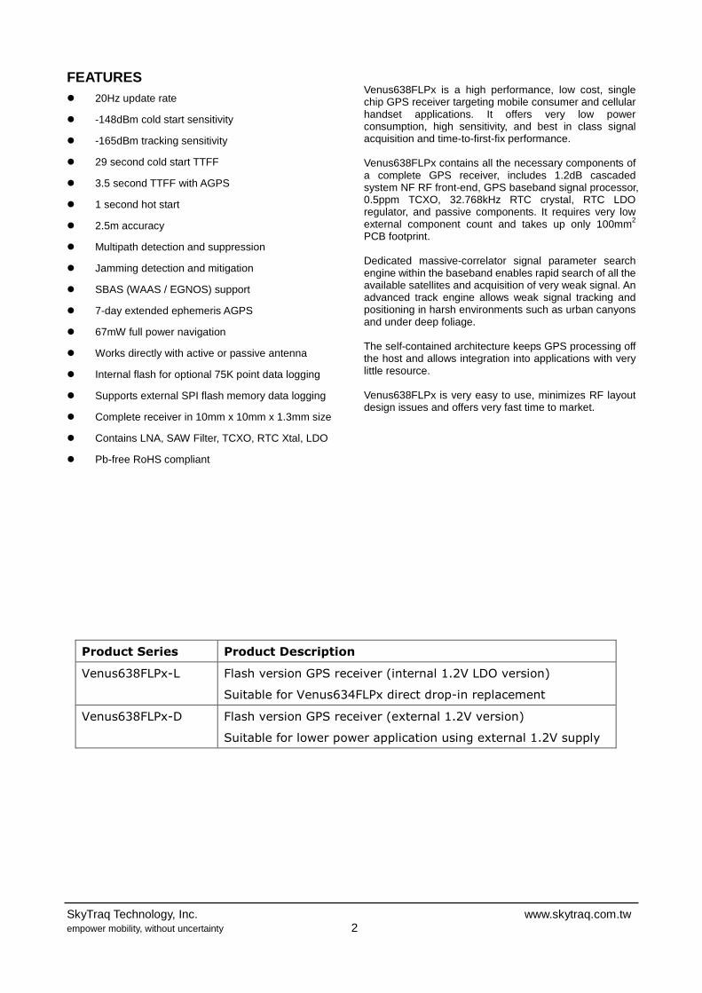
FEATURES � 20Hz update rate
� -148dBm cold start sensitivity
� -165dBm tracking sensitivity
� 29 second cold start TTFF
� 3.5 second TTFF with AGPS
� 1 second hot start
� 2.5m accuracy
� Multipath detection and suppression
� Jamming detection and mitigation
� SBAS (WAAS / EGNOS) support
� 7-day extended ephemeris AGPS
� 67mW full power navigation
� Works directly with active or passive antenna
� Internal flash for optional 75K point data logging
� Supports external SPI flash memory data logging
� Complete receiver in 10mm x 10mm x 1.3mm size
� Contains LNA, SAW Filter, TCXO, RTC Xtal, LDO
� Pb-free RoHS compliant
Venus638FLPx is a high performance, low cost, single chip GPS receiver targeting mobile consumer and cellular handset applications. It offers very low power consumption, high sensitivity, and best in class signal acquisition and time-to-first-fix performance. Venus638FLPx contains all the necessary components of a complete GPS receiver, includes 1.2dB cascaded system NF RF front-end, GPS baseband signal processor, 0.5ppm TCXO, 32.768kHz RTC crystal, RTC LDO regulator, and passive components. It requires very low external component count and takes up only 100mm2 PCB footprint. Dedicated massive-correlator signal parameter search engine within the baseband enables rapid search of all the available satellites and acquisition of very weak signal. An advanced track engine allows weak signal tracking and positioning in harsh environments such as urban canyons and under deep foliage. The self-contained architecture keeps GPS processing off the host and allows integration into applications with very little resource. Venus638FLPx is very easy to use, minimizes RF layout design issues and offers very fast time to market.
Product Series Product Description
Venus638FLPx-L Flash version GPS receiver (internal 1.2V LDO version)
Suitable for Venus634FLPx direct drop-in replacement
Venus638FLPx-D Flash version GPS receiver (external 1.2V version)
Suitable for lower power application using external 1.2V supply

SkyTraq Technology, Inc. www.skytraq.com.tw empower mobility, without uncertainty 3
TECHNICAL SPECIFICATIONS Receiver Type L1 frequency
GPS C/A code SBAS capable 65-channel architecture 8 million time-frequency searches per second
Accuracy Position 2.5m CEP Velocity 0.1m/sec Timing 60ns Open Sky TTFF 29 second cold start
3.5 second with AGPS 1 second hot start
Reacquisition < 1s
Sensitivity -165dBm tracking -148dBm cold start Update Rate 1 / 2 / 4 / 5 / 8 / 10 / 20 Hz (default 1Hz) Dynamics 4G Operational Limits Altitude < 18,000m*1 , Velocity < 515m/s*1 Datum Default WGS-84 Interface UART LVTTL level Baud Rate 4800 / 9600 / 38400 / 115200 Protocol NMEA-0183 V3.01, GGA, GLL, GSA, GSV, RMC, VTG (default GGA, GSA, GSV, RMC, VTG) SkyTraq Binary Main Supply Voltage 2.8V ~ 3.6V (Venus638FLPx-L) 2.8V ~ 3.6V, 1.08V ~ 1.32V (Venus638FLPx-D) Backup Voltage 1.5V ~ 6V Current Consumption
Enhanced Acquisition Low Power Acquisition Tracking Venus638FLPx-L 68mA @ 3.3V 50mA @ 3.3V 29mA @ 3.3V Venus638FLPx-D 18mA @ 3.3V
50mA @ 1.2V 18mA @ 3.3V 32mA @ 1.2V
18mA @ 3.3V 11mA @ 1.2V
Assuming 75% efficiency switch-mode 3.3V-to-1.2V regulator is used, then
Enhanced Acquisition Low Power Acquisition Tracking Venus638FLPx-D 42mA @ 3.3V 33mA @ 3.3V 23mA @ 3.3V
Operating Temperature -40 ~ +85 deg-C Storage Temperature -40 ~ +125 deg-C Package LGA69 10mm x 10mm x 1.3mm, 0.8mm pitch
*1: COCOM limit, either may be exceeded but not both

SkyTraq Technology, Inc. www.skytraq.com.tw empower mobility, without uncertainty 4
BLOCK DIAGRAM
Figure-1 GPS Receiver based on Venus638FLPx

SkyTraq Technology, Inc. www.skytraq.com.tw empower mobility, without uncertainty 5
VENUS638FLPx PIN-OUT DIAGRAM
Figure-2b Venus638FLPx Pin-Out Diagram
VENUS638FLPx PIN DEFINITION
Pin Number Signal Name Type Description 1 RSTN Input Active LOW reset input, 3.3V LVTTL 2 VCC33I Power Input Main voltage supply input, 2.8V ~ 3.6V 3 NC Not connected, empty pin 4 PIO12 Bidir General purpose I/O pin, 3.3V LVTTL 5 GPIO2 Bidir General purpose I/O pin, 3.3V LVTTL 6 GPIO1 Bidir General purpose I/O pin, 3.3V LVTTL
7 LED / GPIO0 Bidir Navigation status indicator or General purpose I/O. 3.3V LVTTL
8 GPIO24 Bidir General purpose I/O pin. 3.3V LVTTL Also serves as Search Engine Mode Selection upon power-up 1: low power acquisition mode 0: enhanced acquisition mode
9 BOOT_SEL Bidir Boot mode selection. Pull-high or pull-low using 10K resistor. Must not connect to VCC or GND directly. 1: execute from internal ROM 0: execute from internal Flash memory
10 GND Power System ground 11 GND Power System ground 12 GPIO22 Bidir General purpose I/O pin, 3.3V LVTTL 13 GPIO23 Bidir General purpose I/O pin, 3.3V LVTTL 14 GPIO20 Bidir General purpose I/O pin, 3.3V LVTTL 15 GND Power System ground 16 GPIO29 Bidir General purpose I/O pin, 3.3V LVTTL 17 V12O_RTC Power Output 1.2V LDO output for RTC & backup memory. Normally unused.

SkyTraq Technology, Inc. www.skytraq.com.tw empower mobility, without uncertainty 6
18 VBAT Power Input Supply voltage for internal RTC and backup SRAM, 1.5V ~ 6V. VBAT should be powered by non-volatile supply voltage to have optimal performance. If VBAT is connected to VCC33I, powered off as VCC33I power is removed, then it’ll cold start every time. For applications that do not care lesser performance cold starting every time, this pin can be connected to VCC33I.
19 GND Power System ground 20 NC Not connected, empty pin 21 GND_RF Power RF section system ground 22 GND_RF Power RF section system ground 23 NC Not connected, empty pin 24 GND_RF Power RF section system ground 25 GND_RF Power RF section system ground 26 NC Not connected, empty pin 27 GND_RF Power RF section system ground 28 GND_RF Power RF section system ground 29 GND_RF Power RF section system ground 30 NC Not connected, empty pin 31 GND_RF Power RF section system ground 32 RFIN Input GPS signal input, connect to GPS antenna. 33 GND_RF Power RF section system ground 34 NC Not connected, empty pin 35 NC Not connected, empty pin 36 REG_ENA Input Connect to pin-2 VCC33I 37 PIO14 Bidir General purpose I/O pin, 3.3V LVTTL 38 MOSI / PIO9 Bidir SPI data output or general purpose I/O pin, 3.3V LVTTL 39 MISO / PIO8 Bidir SPI data input or general purpose I/O pin, 3.3V LVTTL 40 P1PPS Output 1 pulse per second output. Active after position fix; goes HIGH for
about 4msec, 3.3V LVTTL 41 SPI_CLK / PIOO7 Output SPI clock or general purpose output pin, 3.3V LVTTL 42 RXD0 Input Received input of the asynchronous UART port. Used to input
binary command to the GPS receiver. 3.3V LVTTL 43 SPI_CSN / PIO6 Bidir SPI chip select output or general purpose I/O pin, 3.3V LVTTL 44 TXD0 Output Transmit output of the asynchronous UART port. Used to output
standard NMEA-0183 sentence or response to input binary command. 3.3V LVTTL
45 SDA Bidir I2C data, 3.3V I/O 46 SCL Bidir I2C clock, 3.3V I/O 47 GPIO4 Bidir General purpose I/O pin, 3.3V LVTTL 48 GPIO3 Bidir General purpose I/O pin, 3.3V LVTTL 49 GND System ground 50 PIO5 Output General purpose output pin, 3.3V LVTTL 51 PIO11 Bidir General purpose I/O pin, 3.3V LVTTL 52 RXD1 Input Received input of the asynchronous UART port.
3.3V LVTTL 53 GPIO25 Bidir General purpose I/O pin, 3.3V LVTTL 54 GPIO30 Bidir General purpose I/O pin, 3.3V LVTTL 55 PIO15 Bidir General purpose I/O pin, 3.3V LVTTL 56 NC / V12 NC pin for Venus638FLPx-L
1.2V supply input pin for Venus638FLPx-D 57 TXD1 Output Transmit output of the asynchronous UART port.
3.3V LVTTL 58 VCC33I Power Input Main voltage supply input, 2.8V ~ 3.6V 59 GPIO28 Bidir General purpose I/O pin, 3.3V LVTTL 60 GND Power System ground 61 GND_RF Power RF section system ground 62 GND_RF Power RF section system ground 63 GPIO6 Bidir General purpose I/O pin, 3.3V LVTTL 64 GND Power System ground 65 GND_RF Power RF section system ground
66,67,68 NC 69 GND_RF Power RF section system ground
When using Venus638FLPx-L to replace Venus634FLPx, pin-45 ~ pin-69 can all be left unconnected. When using Venus638FLPx-D, 1.2V need to be supplied at pin-56 The NC pins are to be left unconnected.

SkyTraq Technology, Inc. www.skytraq.com.tw empower mobility, without uncertainty 7
DC CHARACTERISTICS OF DIGITAL INTERFACE Below is when VCC3I is at nominally 3.3V
Parameter Min. Typ. Max. Units Input Low Voltage 0.8 Volt Input High Voltage 2.0 Volt Output Low Voltage, Iol = 2 ~ 16mA 0.4 Volt Output High Voltage, Ioh = 2 ~ 16mA 2.9 Volt

SkyTraq Technology, Inc. www.skytraq.com.tw empower mobility, without uncertainty 8
MECHANICAL DIMENSION
RECOMMENDED PCB FOOTPRINT
Figure-3 Recommended PCB Footprint.
SkyTraq Technology, Inc. www.skytraq.com.tw empower mobility, without uncertainty 9
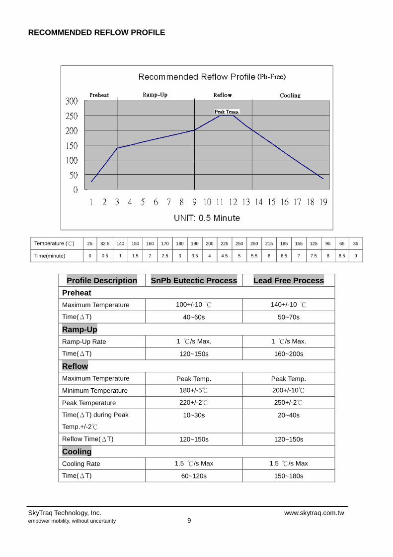
RECOMMENDED REFLOW PROFILE
Temperature (℃) 25 82.5 140 150 160 170 180 190 200 225 250 250 215 185 155 125 95 65 35
Time(minute) 0 0.5 1 1.5 2 2.5 3 3.5 4 4.5 5 5.5 6 6.5 7 7.5 8 8.5 9
Profile Description SnPb Eutectic Process Lead Free Process
Preheat Maximum Temperature 100+/-10 ℃ 140+/-10 ℃
Time(ΔT) 40~60s 50~70s
Ramp-Up Ramp-Up Rate 1 ℃/s Max. 1 ℃/s Max.
Time(ΔT) 120~150s 160~200s
Reflow
Maximum Temperature Peak Temp. Peak Temp.
Minimum Temperature 180+/-5℃ 200+/-10℃
Peak Temperature 220+/-2℃ 250+/-2℃
Time(ΔT) during Peak
Temp.+/-2℃
10~30s 20~40s
Reflow Time(ΔT) 120~150s 120~150s
Cooling Cooling Rate 1.5 ℃/s Max 1.5 ℃/s Max
Time(ΔT) 60~120s 150~180s

5
5
4
4
3
3
2
2
1
1
D D
C C
B B
A A
2
1
3V rechargeablelithium battery
for Venus634FLPx replacement application,these pins can be left unconnected
Skytraq Technology, Inc.
L1 Optional biasingfor active antenna
Optional for data logging application
V638FLPx-L_AP001 1.0
Venus 638FLPx-L Application Circuit
B
1 1Friday, February 26, 2010
Title
Size Document Number Rev
Date: Sheet of
VBAT
GN
D_A
GN
D_A
SPICSN_PIO6MISO_PIO8
SPICLK_PIOO7MOSI_PIO9
GN
D
VBAT
GPI
O20
GPIO2
LED_GPIO0GPIO24
RSTN
PIO12
GPIO1
SPIC
LK_P
IOO
7
PIO
14
MIS
O_P
IO8
P1PP
S
MO
SI_P
IO9
FRXD
0SP
ICSN
_PIO
6
VCC
33
FTXD
0
VCC33
VCC33
VCC33
VCC33
VCC33
VCC33
VCC33
19SPICLK_PIOO7
17SPICSN_PIO6
12 FRXD0
8 GPIO20
15GPIO2
13VBAT
18 MISO_PIO8
20MOSI_PIO9
9VCC33
4GPIO24
16 GND
14 FTXD0
2 LED_GPIO0
6 P1PPS
7RSTN
1GND_A
3PIO12
5GND
11GPIO1
10 PIO14
E1
ANTENNA
1
L133nH
C6
0.1uF
U4
SST25VF040
1234
8765
CSSOWPGND
VCCHOLD
SCKSI
R3 4.7K
U1A
V638FLPx-L
123456789
1011
12 13 14 15 16 17 18 19 20 21 22
44 43 42 41 40 39 38 37 36 35 34
3332313029282726252423
RSTNVCC33INCPIO12GPIO2GPIO1LED/GPIO0GPIO24BOOT_SELGNDGND
GPI
O22
GPI
O23
GPI
O20
GN
DG
PIO
29V1
2O_R
TCVB
ATG
ND
NC
GN
D_R
FG
ND
_RF
TXD
0SP
I_C
SN0/
PIO
6R
XD0
SPI_
CLK
/PIO
O7
P1PP
SM
ISO
/PIO
8M
OSI
/PIO
9PI
O14
REG
_EN
AN
CN
C
GND_RFRFIN
GND_RFNC
GND_RFGND_RFGND_RF
NCGND_RFGND_RF
NC
U1B
V638FLPx-L
45464748
66
505152535455
67
57
68
5963
56
496064
61626569
58
SDASCLGPIO4GPIO3
NC
PIO5PIO11RXD1GPIO25GPIO30PIO15
NC
TXD1
NC
GPIO28GPIO6
NC
GNDGNDGND
GND_RFGND_RFGND_RFGND_RF
VCC33I
C1
1uF
C3
1uF
R1
33K
D1
RB420/RB425
BT1
MS621
R2
390XC1
1uF
AR1 0

5
5
4
4
3
3
2
2
1
1
D D
C C
B B
A A
Optional for data logging application
2
1
3V rechargeablelithium battery
DCDC Converter (1.2V)
Skytraq Technology, Inc.
L1 Optional biasingfor active antenna
V638FLPx-D_AP001 1.0
Venus 638FLPx-D Application Circuit
B
1 1Friday, February 26, 2010
Title
Size Document Number Rev
Date: Sheet of
BBV12
SPICSN_PIO6MISO_PIO8
SPICLK_PIOO7MOSI_PIO9
GN
DSP
ICLK
_PIO
O7
PIO
14
GPIO2
LED_GPIO0
VBAT
VBAT
MIS
O_P
IO8
P1PP
S
MO
SI_P
IO9
GPIO24
FRXD
0SP
ICSN
_PIO
6
VCC
33
VCC33G
ND
_A
RSTN
PIO12
GPI
O20
GPIO1
FTXD
0
GN
D_A
VCC33
VCC33
VCC33
VCC33
VCC33
VCC33
VCC33
19SPICLK_PIOO7
17SPICSN_PIO6
12 FRXD0
8 GPIO20
15GPIO2
13VBAT
18 MISO_PIO8
20MOSI_PIO9
9VCC33
4GPIO24
16 GND
14 FTXD0
2 LED_GPIO0
6 P1PPS
7RSTN
1GND_A
3PIO12
5GND
11GPIO1
10 PIO14
E1
ANTENNA
1
L133nH
U4
SST25VF040
1234
8765
CSSOWPGND
VCCHOLD
SCKSI
C6
0.1uF
R3 4.7K
U1A
V638FLPx-D
123456789
1011
12 13 14 15 16 17 18 19 20 21 22
44 43 42 41 40 39 38 37 36 35 34
3332313029282726252423
RSTNVCC33INCPIO12GPIO2GPIO1LED/GPIO0GPIO24BOOT_SELGNDGND
GPI
O22
GPI
O23
GPI
O20
GN
DG
PIO
29V1
2O_R
TCVB
ATG
ND
NC
GN
D_R
FG
ND
_RF
TXD
0SP
I_C
SN0/
PIO
6R
XD0
SPI_
CLK
/PIO
O7
P1PP
SM
ISO
/PIO
8M
OSI
/PIO
9PI
O14
REG
_EN
AN
CN
C
GND_RFRFIN
GND_RFNC
GND_RFGND_RFGND_RF
NCGND_RFGND_RF
NC
U1B
V638FLPx-D
45464748
66
505152535455
67
57
68
5963
56
496064
61626569
58
SDASCLGPIO4GPIO3
NC
PIO5PIO11RXD1GPIO25GPIO30PIO15
NC
TXD1
NC
GPIO28GPIO6
V12
GNDGNDGND
GND_RFGND_RFGND_RFGND_RF
VCC33I
R1
33K
C3
1uF
C1
1uF
D1
RB420/RB425
R2
390
BT1
MS621XC1
1uF
C5
4.7u
F
C7
10uF
U3
XCL206B123AR
1
2
3
6
5
4
78
910
LX
VSS
VOUT
VIN
VSS
CE/MODE
L1L2
GN
DG
ND
AR1 0
SkyTraq Technology, Inc. www.skytraq.com.tw empower mobility, without uncertainty 10
APPLICATION CIRCUIT INTERFACE SIGNALS GND_A: RF ground LED: Signal to indicate GPS position status, 3.3V LVTTL.
Active low for no-fix, toggle every second after position fix. PSE_SEL: Search engine mode selection, sampled only at end of power-on reset cycle
1: Low power acquisition mode 0: Enhanced acquisition mode
GND: Digital ground P1PPS: 1 pulse per second time-mark (3.3V LVTTL) RSTN: Active low reset input VCC33: 3.3V power input FRXD0: UART input (3.3V LVTTL) FTXD0: UART output (3.3V LVTTL) VBAT: Battery-backed RTC and SRAM supply input, 1.5V ~ 6V, must not be unconnected.
SkyTraq Technology, Inc. www.skytraq.com.tw empower mobility, without uncertainty 11
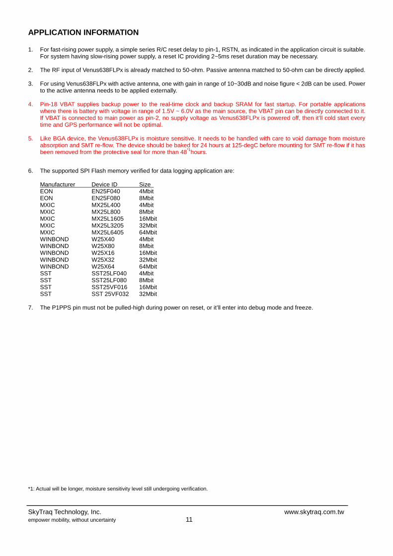
APPLICATION INFORMATION 1. For fast-rising power supply, a simple series R/C reset delay to pin-1, RSTN, as indicated in the application circuit is suitable.
For system having slow-rising power supply, a reset IC providing 2~5ms reset duration may be necessary.
2. The RF input of Venus638FLPx is already matched to 50-ohm. Passive antenna matched to 50-ohm can be directly applied. 3. For using Venus638FLPx with active antenna, one with gain in range of 10~30dB and noise figure < 2dB can be used. Power
to the active antenna needs to be applied externally. 4. Pin-18 VBAT supplies backup power to the real-time clock and backup SRAM for fast startup. For portable applications
where there is battery with voltage in range of 1.5V ~ 6.0V as the main source, the VBAT pin can be directly connected to it. If VBAT is connected to main power as pin-2, no supply voltage as Venus638FLPx is powered off, then it’ll cold start every time and GPS performance will not be optimal.
5. Like BGA device, the Venus638FLPx is moisture sensitive. It needs to be handled with care to void damage from moisture
absorption and SMT re-flow. The device should be baked for 24 hours at 125-degC before mounting for SMT re-flow if it has been removed from the protective seal for more than 48*1hours.
6. The supported SPI Flash memory verified for data logging application are:
Manufacturer Device ID Size EON EN25F040 4Mbit EON EN25F080 8Mbit MXIC MX25L400 4Mbit MXIC MX25L800 8Mbit MXIC MX25L1605 16Mbit MXIC MX25L3205 32Mbit MXIC MX25L6405 64Mbit WINBOND W25X40 4Mbit WINBOND W25X80 8Mbit WINBOND W25X16 16Mbit WINBOND W25X32 32Mbit WINBOND W25X64 64Mbit SST SST25LF040 4Mbit SST SST25LF080 8Mbit SST SST25VF016 16Mbit SST SST 25VF032 32Mbit
7. The P1PPS pin must not be pulled-high during power on reset, or it’ll enter into debug mode and freeze. *1: Actual will be longer, moisture sensitivity level still undergoing verification.
SkyTraq Technology, Inc. www.skytraq.com.tw empower mobility, without uncertainty 12
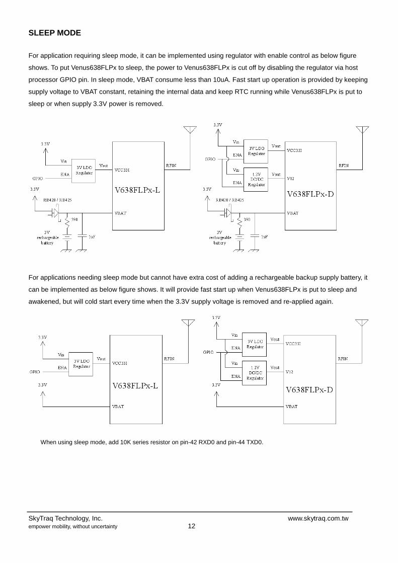
SLEEP MODE
For application requiring sleep mode, it can be implemented using regulator with enable control as below figure
shows. To put Venus638FLPx to sleep, the power to Venus638FLPx is cut off by disabling the regulator via host
processor GPIO pin. In sleep mode, VBAT consume less than 10uA. Fast start up operation is provided by keeping
supply voltage to VBAT constant, retaining the internal data and keep RTC running while Venus638FLPx is put to
sleep or when supply 3.3V power is removed.
For applications needing sleep mode but cannot have extra cost of adding a rechargeable backup supply battery, it
can be implemented as below figure shows. It will provide fast start up when Venus638FLPx is put to sleep and
awakened, but will cold start every time when the 3.3V supply voltage is removed and re-applied again.
When using sleep mode, add 10K series resistor on pin-42 RXD0 and pin-44 TXD0.

SkyTraq Technology, Inc. www.skytraq.com.tw empower mobility, without uncertainty 13
PACKAGE

SkyTraq Technology, Inc. www.skytraq.com.tw empower mobility, without uncertainty 14
NMEA MESSAGES
The full descriptions of supported NMEA messages are provided at the following paragraphs.
GGA - Global Positioning System Fix Data
Time, position and fix related data for a GPS receiver.
Structure:
$GPGGA,hhmmss.sss,ddmm.mmmm,a,dddmm.mmmm,a,x,xx,x.x,x.x,M,,,,xxxx*hh<CR><LF>
1 2 3 4 5 6 7 8 9 10 11
Example:
$GPGGA,111636.932,2447.0949,N,12100.5223,E,1,11,0.8,118.2,M,,,,0000*02<CR><LF>
Field Name Example Description
1 UTC Time 111636.932 UTC of position in hhmmss.sss format, (000000.000 ~ 235959.999)
2 Latitude 2447.0949 Latitude in ddmm.mmmm format
Leading zeros transmitted
3 N/S Indicator N Latitude hemisphere indicator, ‘N’ = North, ‘S’ = South
4 Longitude 12100.5223 Longitude in dddmm.mmmm format
Leading zeros transmitted
5 E/W Indicator E Longitude hemisphere indicator, 'E' = East, 'W' = West
6 GPS quality
indicator
1 GPS quality indicator
0: position fix unavailable
1: valid position fix, SPS mode
2: valid position fix, differential GPS mode
3: GPS PPS Mode, fix valid
4: Real Time Kinematic. System used in RTK mode with fixed integers
5: Float RTK. Satellite system used in RTK mode. Floating integers
6: Estimated (dead reckoning) Mode
7: Manual Input Mode
8: Simulator Mode
7 Satellites Used 11 Number of satellites in use, (00 ~ 12)
8 HDOP 0.8 Horizontal dilution of precision, (00.0 ~ 99.9)
9 Altitude 108.2 mean sea level (geoid), (-9999.9 ~ 17999.9)
10 DGPS Station ID 0000 Differential reference station ID, 0000 ~ 1023
NULL when DGPS not used
11 Checksum 02

SkyTraq Technology, Inc. www.skytraq.com.tw empower mobility, without uncertainty 15
GLL – Latitude/Longitude
Latitude and longitude of current position, time, and status.
Structure:
$GPGLL,ddmm.mmmm,a,dddmm.mmmm,a,hhmmss.sss,A,a*hh<CR><LF>
1 2 3 4 5 6 7 8
Example:
$GPGLL,2447.0944,N,12100.5213,E,112609.932,A,A*57<CR><LF>
Field Name Example Description
1 Latitude 2447.0944 Latitude in ddmm.mmmm format
Leading zeros transmitted
2 N/S Indicator N Latitude hemisphere indicator
‘N’ = North
‘S’ = South
3 Longitude 12100.5213 Longitude in dddmm.mmmm format
Leading zeros transmitted
4 E/W Indicator E Longitude hemisphere indicator
'E' = East
'W' = West
5 UTC Time 112609.932 UTC time in hhmmss.sss format (000000.000 ~
235959.999)
6 Status A Status, ‘A’ = Data valid, ‘V’ = Data not valid
7 Mode Indicator A Mode indicator
‘N’ = Data not valid
‘A’ = Autonomous mode
‘D’ = Differential mode
‘E’ = Estimated (dead reckoning) mode
‘M’ = Manual input mode
‘S’ = Simulator mode
8 Checksum 57

SkyTraq Technology, Inc. www.skytraq.com.tw empower mobility, without uncertainty 16
GSA – GNSS DOP and Active Satellites
GPS receiver operating mode, satellites used in the navigation solution reported by the GGA or GNS sentence and
DOP values.
Structure:
$GPGSA,A,x,xx,xx,xx,xx,xx,xx,xx,xx,xx,xx,xx,xx,x.x,x.x,x.x*hh<CR><LF>
1 2 3 3 3 3 3 3 3 3 3 3 3 3 4 5 6 7
Example:
$GPGSA,A,3,05,12,21,22,30,09,18,06,14,01,31,,1.2,0.8,0.9*36<CR><LF>
Field Name Example Description
1 Mode A Mode
‘M’ = Manual, forced to operate in 2D or 3D mode
‘A’ = Automatic, allowed to automatically switch 2D/3D
2 Mode 3 Fix type
1 = Fix not available
2 = 2D
3 = 3D
3 Satellite used 1~12 05,12,21,22,3
0,09,18,06,14,
01,31,,
Satellite ID number, 01 to 32, of satellite used in solution,
up to 12 transmitted
4 PDOP 1.2 Position dilution of precision (00.0 to 99.9)
5 HDOP 0.8 Horizontal dilution of precision (00.0 to 99.9)
6 VDOP 0.9 Vertical dilution of precision (00.0 to 99.9)
7 Checksum 36

SkyTraq Technology, Inc. www.skytraq.com.tw empower mobility, without uncertainty 17
GSV – GNSS Satellites in View
Number of satellites (SV) in view, satellite ID numbers, elevation, azimuth, and SNR value. Four satellites
maximum per transmission.
Structure:
$GPGSV,x,x,xx,xx,xx,xxx,xx,…,xx,xx,xxx,xx *hh<CR><LF>
1 2 3 4 5 6 7 4 5 6 7 8
Example:
$GPGSV,3,1,12,05,54,069,45,12,44,061,44,21,07,184,46,22,78,289,47*72<CR><LF>
$GPGSV,3,2,12,30,65,118,45,09,12,047,37,18,62,157,47,06,08,144,45*7C<CR><LF>
$GPGSV,3,3,12,14,39,330,42,01,06,299,38,31,30,256,44,32,36,320,47*7B<CR><LF>
Field Name Example Description
1 Number of message 3 Total number of GSV messages to be transmitted (1-3)
2 Sequence number 1 Sequence number of current GSV message
3 Satellites in view 12 Total number of satellites in view (00 ~ 12)
4 Satellite ID 05 Satellite ID number, GPS: 01 ~ 32, SBAS: 33 ~ 64 (33 =
PRN120)
5 Elevation 54 Satellite elevation in degrees, (00 ~ 90)
6 Azimuth 069 Satellite azimuth angle in degrees, (000 ~ 359 )
7 SNR 45 C/No in dB (00 ~ 99)
Null when not tracking
8 Checksum 72
SkyTraq Technology, Inc. www.skytraq.com.tw empower mobility, without uncertainty 18
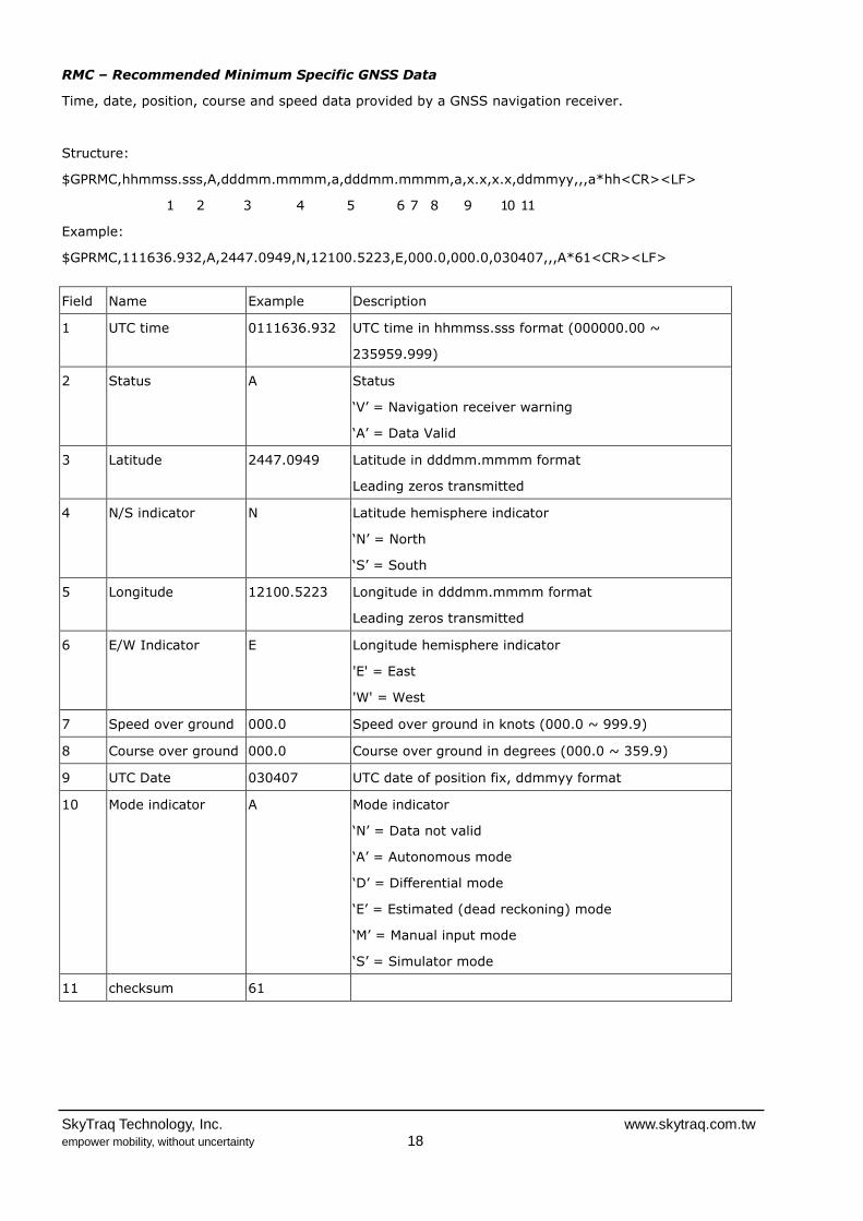
RMC – Recommended Minimum Specific GNSS Data
Time, date, position, course and speed data provided by a GNSS navigation receiver.
Structure:
$GPRMC,hhmmss.sss,A,dddmm.mmmm,a,dddmm.mmmm,a,x.x,x.x,ddmmyy,,,a*hh<CR><LF>
1 2 3 4 5 6 7 8 9 10 11
Example:
$GPRMC,111636.932,A,2447.0949,N,12100.5223,E,000.0,000.0,030407,,,A*61<CR><LF>
Field Name Example Description
1 UTC time 0111636.932 UTC time in hhmmss.sss format (000000.00 ~
235959.999)
2 Status A Status
‘V’ = Navigation receiver warning
‘A’ = Data Valid
3 Latitude 2447.0949 Latitude in dddmm.mmmm format
Leading zeros transmitted
4 N/S indicator N Latitude hemisphere indicator
‘N’ = North
‘S’ = South
5 Longitude 12100.5223 Longitude in dddmm.mmmm format
Leading zeros transmitted
6 E/W Indicator E Longitude hemisphere indicator
'E' = East
'W' = West
7 Speed over ground 000.0 Speed over ground in knots (000.0 ~ 999.9)
8 Course over ground 000.0 Course over ground in degrees (000.0 ~ 359.9)
9 UTC Date 030407 UTC date of position fix, ddmmyy format
10 Mode indicator A Mode indicator
‘N’ = Data not valid
‘A’ = Autonomous mode
‘D’ = Differential mode
‘E’ = Estimated (dead reckoning) mode
‘M’ = Manual input mode
‘S’ = Simulator mode
11 checksum 61

SkyTraq Technology, Inc. www.skytraq.com.tw empower mobility, without uncertainty 19
VTG – Course Over Ground and Ground Speed
The Actual course and speed relative to the ground.
Structure:
GPVTG,x.x,T,,M,x.x,N,x.x,K,a*hh<CR><LF>
1 2 3 4 5
Example:
$GPVTG, 000.0,T,,M,000.0,N,0000.0,K,A*3D<CR><LF>
Field Name Example Description
1 Course 000.0 True course over ground in degrees (000.0 ~ 359.9)
2 Speed 000.0 Speed over ground in knots (000.0 ~ 999.9)
3 Speed 0000.0 Speed over ground in kilometers per hour (0000.0 ~
1800.0)
4 Mode A Mode indicator
‘N’ = not valid
‘A’ = Autonomous mode
‘D’ = Differential mode
‘E’ = Estimated (dead reckoning) mode
‘M’ = Manual input mode
‘S’ = Simulator mode
5 Checksum 3D

SkyTraq Technology, Inc. www.skytraq.com.tw empower mobility, without uncertainty 20
ORDERING INFORMATION
Part Number Description
Venus638FLPx-L Flash version GPS receiver (internal 1.2V LDO version)
Venus638FLPx-D Flash version GPS receiver (external 1.2V version)
SkyTraq Technology, Inc. 4F, No.26, Minsiang Street, Hsinchu, Taiwan, 300 Phone: +886 3 5678650 Fax: +886 3 5678680 Email: [email protected] © 2008 SkyTraq Technology Inc. All rights reserved. Not to be reproduced in whole or part for any purpose without written permission of SkyTraq Technology Inc (“SkyTraq”). Information provided by SkyTraq is believed to be accurate and reliable. These materials are provided by SkyTraq as a service to its customers and may be used for informational purposes only. SkyTraq assumes no responsibility for errors or omissions in these materials, nor for its use. SkyTraq reserves the right to change specification at any time without notice. These materials are provides “as is” without warranty of any kind, either expressed or implied, relating to sale and/or use of SkyTraq products including liability or warranties relating to fitness for a particular purpose, consequential or incidental damages, merchantability, or infringement of any patent, copyright or other intellectual property right. SkyTraq further does not warrant the accuracy or completeness of the information, text, graphics or other items contained within these materials. SkyTraq shall not be liable for any special, indirect, incidental, or consequential damages, including without limitation, lost revenues or lost profits, which may result from the use of these materials. SkyTraq products are not intended for use in medical, life-support devices, or applications involving potential risk of death, personal injury, or severe property damage in case of failure of the product.
SkyTraq Technology, Inc. www.skytraq.com.tw empower mobility, without uncertainty 21
Change Log Version 0.7, January 25, 2011 1. Changed latitude, longitude, speed, heading number of digits back to original format due to customer backward
compatibility issue Version 0.6, October 20, 2010 1. Edited performance spec due to firmware enhancement 2. Added 1 more decimal digit to latitude, longitude, speed, heading in NMEA sentence Version 0.5, August 31, 2010 1. Added application information on P1PPS pin Version 0.4, August 3, 2010 1. Pin-1 orientation in the shipping tray rotated 90-degree Version 0.3, April 6, 2010 1 Modified for Flash type Version 0.2, March 24, 2010 1. Added current consumption number for –D version at 3.3V
Version 0.1, February 24, 2010 1. Initial release


