5 CONFIGURATION .................................................................................................................................................. 8 6 MEASUREMENTS USING COMBINATION MEASURING SENSOR TFS0100 ................................................. 11 7 MEASUREMENTS USING FLOW MEASURING PROBES STS005 / STS020 .................................................. 11 8 NOTES TO SPECIAL FUNCTIONS ..................................................................................................................... 12
8.1 ZERO DISPLACEMENT (’OFFSET’) ...................................................................................................................... 12 8.2 DISPLAY CORRECTION FACTOR (’CORR’) ........................................................................................................... 12 8.3 BASE ADDRESS (’ADR.’) .................................................................................................................................... 12 8.4 ALARM ............................................................................................................................................................. 12 8.5 REAL TIME CLOCK ............................................................................................................................................ 12
9 DATA LOGGER .................................................................................................................................................... 13 9.1 STORING OF INDIVIDUAL VALUES: "FUNC STOR" ................................................................................................. 13 9.2 HOW TO DISPLAY INDIVIDUAL VALUES ................................................................................................................ 13 9.3 CYCLIC LOGGER FUNCTION: "FUNC CYCL" ....................................................................................................... 13
10 HOW TO CALIBRATE MEAS. OF REL. HUMIDITY USING TFS 0100 ........................................................... 14 11 SYSTEM AND ERROR MESSAGES ................................................................................................................ 15
11.1 MESSAGES AT DEVICE STARTUP ..................................................................................................................... 15 11.2 SYSTEM AND ERROR MESSAGES ................................................................................................................... 15 11.3 SYSTEM AND ERROR MESSAGES DURING TFS0100 CALIBRATION ................................................................... 16
12 THE SERIAL INTERFACE ................................................................................................................................ 16 13 RESHIPMENT AND DISPOSAL ....................................................................................................................... 17
H40.0.21.6C-12 Operating Manual GMH 3350 Page 3 of 18
1 General Note
Read this document carefully and get used to the operation of the device before you use it. Keep this document within easy reach near the device for consulting in case of doubt.
Mounting, start-up, operating, maintenance and removing from operation must be done by qualified, specially trained staff that have carefully read and understood this manual before starting any work.
The manufacturer will assume no liability or warranty in case of usage for other purpose than the intended one, ig-noring this manual, operating by unqualified staff as well as unauthorized modifications to the device. The manufacturer is not liable for any costs or damages incurred at the user or third parties because of the usage or application of this device, in particular in case of improper use of the device, misuse or malfunction of the connection or of the device. The manufacturer is not liable for misprints.
2 Safety
2.1 Intended Use
The safety requirements (see below) have to be observed. The device must be used only according to its intended purpose and under suitable conditions. Use the device carefully and according to its technical data (do not throw it, strike it, …) The device combined with the combined measuring probe TFS 0100 is designed for room climate measurements. This includes gauging of atmospheric humidity, temperature, dew point, dew point distance and enthalpy.
Together with the flow rate measuring probes STS 005 and STS 020 the device provides flow rate measurements either in water or in air.
The device features a lot of useful features as for example min-/max-alarm, hold, real-time clock, interface etc. Furthermore the device has an integrated logger, which can save up to 5400 data sets (at cyclic measurement).
Protect the device from dirt.
2.2 Safety signs and symbols
Warnings are labelled in this document with the followings signs:
DANGER
Caution! This symbol warns of imminent danger, death, serious injuries and significant damage to property at non-observance.
Attention! This symbol warns of possible dangers or dangerous situations
which can provoke damage to the device or environment at non-observance.
Note! This symbol point out processes which can indirectly influence opera-
tion or provoke unforeseen reactions at non-observance.
2.3 Safety guidelines
This device has been designed and tested in accordance with the safety regulations for electronic devices. However, its trouble-free operation and reliability cannot be guaranteed unless the standard safety measures and special safety advises given in this manual will be adhered to when using the device.
1. Trouble-free operation and reliability of the device can only be guaranteed if the device is not subjected to any other climatic conditions than those stated under "Specification". If the device is transported from a cold to a warm environment condensation may cause in a failure of the func-tion. In such a case make sure the device temperature has adjusted to the ambient temperature before trying a new start-up.
2. If there is a risk whatsoever involved in running it, the device has to be switched off immediately and to be marked accordingly to avoid re-starting. Operator safety may be a risk if: - there is visible damage to the device - the device is not working as specified - the device has been stored under unsuitable conditions for a longer time. In case of doubt, please return device to manufacturer for repair or maintenance.
_DANGER
H40.0.21.6C-12 Operating Manual GMH 3350 Page 4 of 18
3. When connecting the device to other devices the connection has to be designed most thoroughly as internal connections in third-party devices (e.g. connection GND with protective earth) may lead to undesired voltage po-tentials that can lead to malfunctions or destroying of the device and the connected devices.
This device must not be run with a defective or damaged power supply unit. Danger to life due to electrical shock!
4. Do not use these products as safety or emergency stop devices or in any other application where failure of the product could result in personal injury or material damage. Failure to comply with these instructions could result in death or serious injury and material dam-age.
3 Product Specification
3.1 Scope of supply
The scope of supply includes:
Device GMH3350, incl. 9V battery block
Operation manual
3.2 Operation and maintenance advice
• Battery operation: If ‘bAt’ is shown in the lower display the battery has been used up and needs to be replaced. However, the device will operate correctly for a certain time. If ‘bAt’ is shown in the upper display the voltage is too low to operate the device; the battery has been completely used up.
The battery has to be taken out, when storing device above 50 °C. We recommend taking out battery if device is not used for a longer period of time. After recommissioning the real-time clock has to be set again.
• Mains operation with power supply When using a power supply please note that operating voltage has to be 10.5 to 12 V DC. Do not apply overvoltage!! Cheap 12V-power supplies often have excessive no-load voltage. We, therefore, recommend using regulated voltage power supplies.
Trouble-free operation is guaranteed by our power supply GNG10/3000. Prior to connecting the power supply to the mains makes sure that the operating voltage stated at the power sup-ply is identical to the mains voltage.
Treat device and sensor carefully. Use only in accordance with above specification. (do not throw, hit against etc.). Protect plug and socket from soiling. Only use the specified sensors (p.r.t. chapter 4.3 “ Connections” on page 6). Connecting the instrument to others, may damaged the instrument and the probe
When connecting the TFS or STS - probe the connector may not lock correctly. In such case take the plug not at the casing but at the buckling protection at the end of the plug. If plug is entered correctly, it will slide in smoothly.
To disconnect sensor/probe the interface or the power supply device, do not pull at the cable but at the plug.
Switch off instrument to change sensors.
_DANGER
_DANGER
H40.0.21.6C-12 Operating Manual GMH 3350 Page 5 of 18
%
°C
r.H.
Td T2Td
m/s
kJ/kg
AL Logg
T1Corr
CAL
MAX
MIN HLD
%
°C
r.H.
Td T2Td
m /s
kJ/kg
AL Logg
T1Corr
CAL
4 Handling
4.1 Display
Depending on the measuring probes/sensors connected the following measuring results can be dis-played:
TFS 0100:
Main display:
r.H.: relative atmospheric humidity in %
Secondary display: possible views:
T1: temperature of the TFS 0100
Td: dew point temperature of air
kJ/kg: enthalpy
with surface temperature probe at T2:
T2: surface temperature
Td: dew point ratio = T2 - Td
The desired secondary display view can be selected by
pressing the -key.
STS 005 or STS 020:
Main display:
m/s: flow rate
Secondary display:
t.AVG: time left till average flow value in sec-onds will be displayed
with temperature probe at T2 and as soon as the averaging time has been reached:
T2: temperature
Special display elements:
Min/Max/Hold:
shows if a min., max. or hold value is displayed in either the main or the secondary display
CAL arrow: indicates that a humidity calibration is carried out at the moment
Warning triangle: indicates a low battery, full logger storage, etc.
Corr arrow: indicates that correction factor is activated
Logger arrow: indicates that the logger function is activated.
Alarm arrow: indicates an alarm
Messages at device startup: The device will show some messages at the startup depended on the configuration and the connected sensor. Further information about the displays can be founded in the chapter “system and error mes-sages” or by the display in the chapter “configuration”.
Note: the message display can be aborted by pressing any key (keys 2 - 6) after the segment test.
H40.0.21.6C-12 Operating Manual GMH 3350 Page 6 of 18
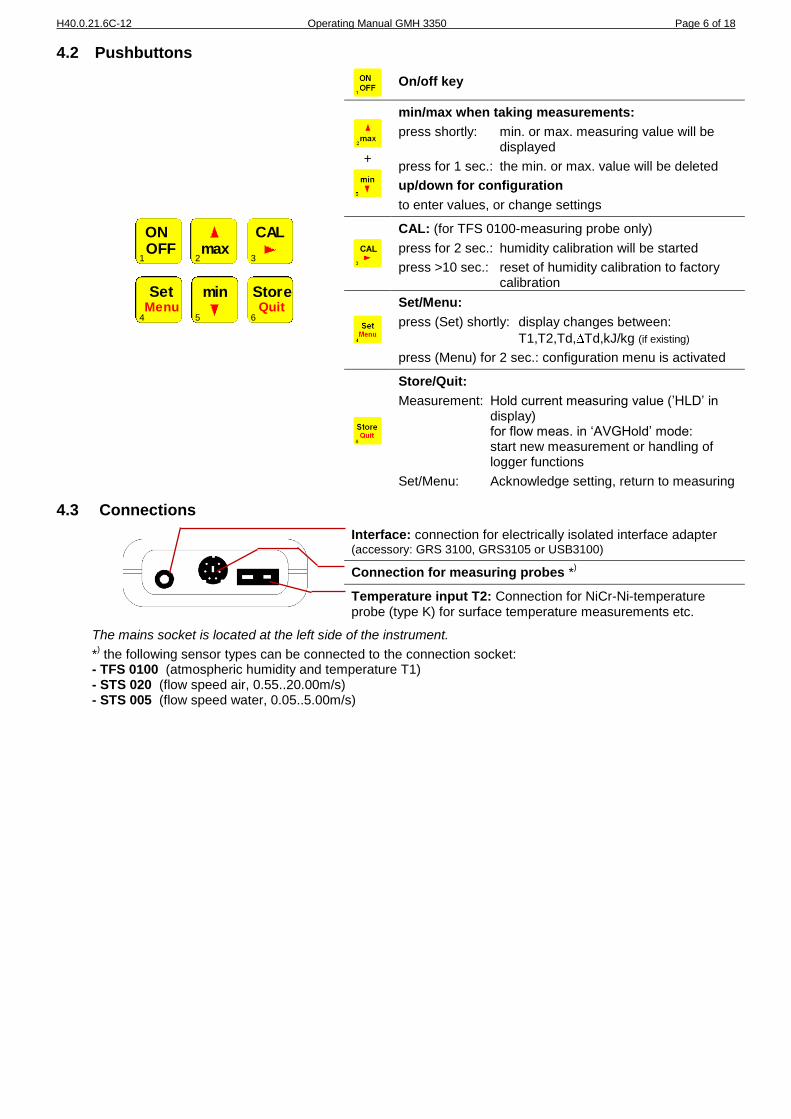
4.2 Pushbuttons
On/off key
+
min/max when taking measurements:
press shortly: min. or max. measuring value will be displayed
press for 1 sec.: the min. or max. value will be deleted
up/down for configuration
to enter values, or change settings
CAL: (for TFS 0100-measuring probe only)
press for 2 sec.: humidity calibration will be started
press >10 sec.: reset of humidity calibration to factory calibration
Set/Menu:
press (Set) shortly: display changes between:
T1,T2,Td, Td,kJ/kg (if existing)
press (Menu) for 2 sec.: configuration menu is activated
Store/Quit:
Measurement: Hold current measuring value (’HLD’ in display) for flow meas. in ‘AVGHold’ mode: start new measurement or handling of logger functions
Set/Menu: Acknowledge setting, return to measuring
4.3 Connections
Interface: connection for electrically isolated interface adapter (accessory: GRS 3100, GRS3105 or USB3100)
Connection for measuring probes *)
Temperature input T2: Connection for NiCr-Ni-temperature probe (type K) for surface temperature measurements etc.
The mains socket is located at the left side of the instrument.
*) the following sensor types can be connected to the connection socket:
H40.0.21.6C-12 Operating Manual GMH 3350 Page 7 of 18
4.4 Pop-up clip
Handling: • Pull at label “open” in order to swing open the pop-up clip. • Pull at label “open” again to swing open the pop-up clip further.
Pop-up clip closed
Pop-up clip at position 90°
Pop-up clip at position 180°
Function:
• The device with a closed pop-up clip can be plainly laid onto a table or attached to a belt, etc.
• The device with pop-up clip at position 90° can be set up on a table, etc.
• The device with pop-up clip at position 180° can be suspended from a screw or the magnetic holder GMH 1300.
Device attached to a belt
Device set up on a table
Device suspended from
magnetic holder GMH 1300
H40.0.21.6C-12 Operating Manual GMH 3350 Page 8 of 18
5 Configuration
Note: Some menu items will be shown depending on the actual device configuration (e.g. there are some items disabled when the logger contains data). Please note the hints by the menu items.
For configuration of the device press -key for 2 seconds: the main menu of the configuration will be called up.
Use key to select a sub-menu, use the key to actually go into the selected sub-menu and to change parame-ters.
Use the keys and to set the individual value for the parameter. Press the key again to memorize the
changes ant to change to the main menu. Use key to leave the configuration.
’Read Logger’: Read Out Logger Data (will be displayed only if data are memorized in the individual value logger mode)
For more information please refer to the chapter 9.2 “How to Display Individual Values “on page 13.
’Set Configuration’: General Device Configurations
Setting general configuration:
Please note: the points marked by *1 will only be displayed if no data is stored
in the logger.
’AVG’: Selection of Averaging Proceedings for Flow Measurement *1 (only STS005/020)
Cont: continuous averaging - the average value calculated from
the measurements conducted during the averaging period will be displayed.
Hold: press key for averaging - flow measurements will be taken during
the averaging period, then the average value will be calculated and displayed till the next flow measurement is started.
’t.AVG’: Setting of Averaging Period *1 (only STS005/020)
1..30: Time for averaging (in seconds) during flow measuring
’Unit’: Selection of Temperature Unit *1
°C: All temperature values in degrees Celsius
°F: All temperature values in degrees Fahrenheit
’Offset T1’: Zero Displacement of Sensor Tempera-ture T1 *1
(only TFS0100)
-10.0°C...10.0°C or -18.0°F...18.0°F:
The zero point of the measurement of T1 will be displaced by this value.
off: Zero point displacement is deactivated (=0.0°)
’Offset T2’: Zero Displacement of Temperature T2 *1
-10.0°C...10.0°C or -18.0°F...18.0°F:
The zero point of the measurement of T2 will be displaced by this value.
off: Zero point displacement is deactivated (=0.0°)
r.H.
Td T2Td
m/s
kJ/kg
AL Logg
T1Corr
CAL
r.H.
Td T2Td
m/s
kJ/kg
AL Logg
T1Corr
CAL
r.H.
Td T2Td
m/s
kJ/kg
AL Logg
T1Corr
CAL
max
min
2
5
r.H.
Td T2Td
m/s
kJ/kg
AL Logg
T1Corr
CAL
max
min
2
5
°C
r.H.
Td T2Td
m/s
kJ/kg
AL Logg
T1Corr
CAL
max
min
2
5
°C
r.H.
Td T2Td
m/s
kJ/kg
AL Logg
T1Corr
CAL
max
min
2
5
°C
r.H.
Td T2Td
m/s
kJ/kg
AL Logg
T1Corr
CAL
max
min
2
5
H40.0.21.6C-12 Operating Manual GMH 3350 Page 9 of 18
’Corr’: Selection of Display Correction Factor *1
1.001...1.200: The temperature value (referring to 0°C or. 32°F) will be multiplied by this factor.
off: Factor is deactivated (=1.000)
’Power.off’: Selection of Power-Off Delay
1...120: Power-off delay in minutes. Device will be automatically switched off as soon as this time has elapsed if no key is pressed/no interface communication takes place. (automati-cally deactivated for cyclic loggers)
off: automatic power-off function deactivated (continuous operation, e.g. in case of mains operation)
’Address’: Selection of Base Address
01, 11, 21, …, 91:
Base address for interface communication. Channel 1 will be addressed by the set base address, chan-nel 2 to 6 will have the following addresses.
Using the interface converter GRS3105 it is possible to connect several devices to a single interface. As a precondition the base addresses of all devices must not be identical. In case several devices are con-nected via one interface make sure to configurate the base addresses accordingly.
’Set Alarm’: Alarm Settings
Settings for the alarm function:
Please note: the points marked by *2 will only be displayed if the alarm functions
'on' or ‘no'.So' have been selected.
’Alarm’: Selection of Alarm Function
off:
Alarm off
no.So Alarm on, the "AL" arrow will be displayed in case of alarm
on: Alarm on, in case of alarm the "AL" arrow will be displayed; in addition an audible alarm signal will be given.
’Alarm Input’: Selection of Alarm Input *2
arrow points to the input channel
’Alarm Low’: Setting of Min. Alarm *2
Setting of the display limit value triggering a min. alarm.
’Alarm High’: Setting of Max. Alarm *2
Setting of the display limit value triggering a max. alarm
r.H.
Td T2Td
m/s
kJ/kg
AL Logg
T1Corr
CAL
max
min
2
5
r.H.
Td T2Td
m/s
kJ/kg
AL Logg
T1Corr
CAL
max
min
2
5
r.H.
Td T2Td
m/s
kJ/kg
AL Logg
T1Corr
CAL
max
min
2
5
r.H.
Td T2Td
m/s
kJ/kg
AL Logg
T1Corr
CAL
r.H.
Td T2Td
m/s
kJ/kg
AL Logg
T1Corr
CAL
max
min
2
5
r.H.
Td T2Td
m/s
kJ/kg
AL Logg
T1Corr
CAL
max
min
2
5
r.H.
Td T2Td
m/s
kJ/kg
AL Logg
T1Corr
CAL
%
max
min
2
5
%
r.H.
Td T2Td
m/s
kJ/kg
AL Logg
T1Corr
CAL
max
min
2
5
H40.0.21.6C-12 Operating Manual GMH 3350 Page 10 of 18
’Set Logger’: Logger Settings
(not possible if there are data in the logger memory)
Setting for the logger function:
’Function’: Selection of Logger Function
off: Logger function off (Use key 6 for Hold-function)
Stor: Individual value logger (Press key 6 to store an individual value set)
CYCL: Cyclic logger (Start by pressing key 6) note: if function "AVG Hold" is chosen, the cyclic logger is not supported.
’Cycle Time’: Setting of Cycle Time (only with Func = CYCL)
1 ... 3600: Cycle time in seconds giving the intervals between the logger data recordings
’Set Clock’: Setting of the Real-Time Clock
Setting of the internal real-time clock:
’Clock’: Set the Time
Setting of the time (hours : minutes)
’Year’: Set the Year
Setting of the year. Time span that can be set: 1997 ... 2100
’Date’: Set the Date
Setting of the date (day.month)
r.H.
Td T2Td
m/s
kJ/kg
AL Logg
T1Corr
CAL
r.H.
Td T2Td
m/s
kJ/kg
AL Logg
T1Corr
CAL
max
min
2
5
r.H.
Td T2Td
m/s
kJ/kg
AL Logg
T1Corr
CAL
max
min
2
5
r.H.
Td T2Td
m/s
kJ/kg
AL Logg
T1Corr
CAL
r.H.
Td T2Td
m/s
kJ/kg
AL Logg
T1Corr
CAL
max
min
2
5
r.H.
Td T2Td
m/s
kJ/kg
AL Logg
T1Corr
CAL
max
min
2
5
r.H.
Td T2Td
m/s
kJ/kg
AL Logg
T1Corr
CAL
max
min
2
5
H40.0.21.6C-12 Operating Manual GMH 3350 Page 11 of 18
6 Measurements Using Combination Measuring Sensor TFS0100
The TFS0100 has been especially designed to carry out measurements of ambient temperature. All TFS0100-probes are interchangeable without recalibration being required. The scope of supply includes one sensor to meas-ure relative atmospheric humidity and another one to measure the ambient temperature T1.
rel. humidity r.H. [%] relative humidity measured in the tip of the probe. Resolution 0.1%
Ambient temperature T1 temperature measured in the tip of the probe. Resolution 0.1°C or 0.1°F.
Other values on display will be calculated by the measuring device (acc. to Mollier diagram):
Dew point temperature Td
Cold air cannot absorb as much steam as warm air. This means that the relative humidity increases as the tempera-ture decreases. If 100% have been reached, the air is saturated with steam; another decrease in temperature results in part of the steam condensing to water, becoming visible as fog or precipitation (dew). The dew point temperature indicates at which temperature a 100% saturation would be reached and as of when "dew" can be expected.
Enthalpy h [kJ/kg] Enthalpy refers to the energy content of air. This value always refers to dry air at 0° C. I.e. the energy content of air with a relative humidity of 0% and 0°C is 0kJ/kg. The warmer the air the higher the relative humidity, the higher the energy content. Therefore, more energy is required to heat up humid air than dry air.
All humidity and temperature values calculated from the measuring values refer to a standard atmos-pheric pressure of 1013 mbar. For measuring atmospheric air, the deviations do not have to be taken into account. When taking measurements in pressure vessels or under similar conditions, the values have to be cor-rected in accordance with a suitable correction table.
Additional Measurements with NiCr-Ni-Surface Probe at T2:
Surface temperature T2 The second temperature channel can amongst other things be used to take measurements of surface temperatures.
Dew point distance Td This measurement refers to measurements of T1, T2 and relative atmospheric humidity. The combination sensor is used to measure the ambient air, whose condition is used to calculate the dew point Td.
The surface sensor is used to measure surfaces within this ambient air, with Td stating the temperature difference between those measurements and the dew point. Example: measuring the ambient temperature results in a Td of 5°C. As long as the surface-temperature (T2) of a
window exceeds 5°C ( Td > 0°C) the surface won´t sweat! When T2 falls below 5°C, ( Td < 0°C) it will sweat. Other examples for application: detection of 'humid corners', monitoring of heat exchangers, weather forecast etc..
7 Measurements Using Flow Measuring Probes STS005 / STS020 Two types of measuring probes are available for flow speed measurements: Please note: -use STS 005 to measure water flow
-use STS 020 to measure air flow Incorrect use will result in incorrect measurements! Please observe max. measuring ranges for flow measurements!
-STS 005: 0.05 ... 5.00 m/s (water) -STS 020: 0.55 ... 20.00 m/s (air)
Higher speeds may destroy the measuring head or may, at least, permanently influence measuring accuracy. An arrow on the measuring head indicates the required flow direction. Flow measuring probes are 'free-jet calibrated', i.e. the diameter of the flow channel has to be 5 times bigger than the diameter of the flow measuring head (= approx. 5 cm, otherwise measuring errors up to 40%). When evaluating the measuring results please also note that in a channel the flow speed is usually higher in the middle of the channel than at its edges. Therefore, use appropriate tables to calculate air flow by means of flow speed.
Averaging for Flow Measurements: When taking flow measurements fluctuations tend to be quite high. To be able to display a stable measuring value two averaging functions have been integrated in the instrument.
H40.0.21.6C-12 Operating Manual GMH 3350 Page 12 of 18
Continuous Averaging The average value displayed has been calculated from the past few measurements conducted during the averaging time set. After the instrument has been switched on the time remaining till expiration of the averaging time will be displayed at the bottom line of the display. The min. and max. values memorized refer to the minimum and/or maxi-mum average value displayed.
Average Hold As soon as the GMH3350 instrument has been switched on the device starts calculating the average flow value dur-ing the averaging time. During measuring the current measuring value will be shown in the top line of the display while the bottom line shows the remaining measuring time. As soon as measurements have been completed the average value will be displayed and the device will switch to the HOLD mode. The min. and max. values memorized refer to the minimum and/or maximum measuring value established during averaging. To start a new measuring series press the key "Store" (key 6).
Additional Measurements with any NiCr-Ni-Temperature Probe at T2: Use temperature channel T2 to take measurements of medium temperature, for example. The value shown ist not an average value.
8 Notes to Special Functions
8.1 Zero Displacement (’Offset’)
A zero displacement can be carried out for each of the two temperature channels T1 (TFS0100 only) and T2:
temperature displayed = temperature measured - offset
Standard setting: 'off' = 0.0°, i.e. no zero displacement will be carried out. The zero displacement is mainly used to compensate for sensor deviations. Unless 'off' is set, this value will be displayed shortly after the device is switched on; during operation it will be identified by means of the Corr-arrow in the display.
8.2 Display Correction Factor (’Corr’)
This factor is applied only to the NiCr-Ni-input T2.
temperature displayed [°C] = temperature measured [°C] * Corr or temperature displayed [°F] = (temperature measured [°F]-32°F) * Corr + 32°F Standard setting: ’off’ =1.000 This factor is used to compensate for losses of transfer in case of surface measurements, occurring if the object to be measured is extremely hot but will be cooled by lower ambient temperatures. The same can be true for sensors with a large mass. Unless ’off’ is set, this value will be displayed shortly after the device is switched on; during opera-tion it will be identified by means of the Corr-arrow in the display.
8.3 Base Address (’Adr.’)
Using the interface converter GRS3105 it is possible to connect several instruments to a single interface. As a pre-condition the base addresses of all devices must not be identical. In case several devices will be connected via one interface make sure to configurate the base addresses accordingly. Channel 1 will be addressed by the base address set, channels 2 - 6 will have the following addresses. (Example: base address 21 - channel 1 = 21, channel 2 = 22, …, channel 6 = 26)
8.4 Alarm
3 alarm settings are available: off (off), on with horn sound (on), on - no horn sound (no.So) Depending on the sensors in use there is the choice of which channel is surveyed by the alarm function. If the alarm function (on, no.So) has been activated, an audible alarm signal will be given with the following cases:
values have fallen below/exceeded the lower/upper alarm limits in the channel to be monitored
FE 9 or FE11 at the channel to be monitored
low battery
FE 7: In case of a system error the horn will be sounded regardless of the alarm setting (even if alarm = off) If one or more alarm settings have been fulfilled the "alarm" arrow will be shown in the display; in case of access via the interface the ’PRIO’-Flag will appear.
8.5 Real Time Clock
The real time clock is required to put logger data in a time order. If necessary please check the setting: Setting via keys (p.r.t. configuration of the device): time (minutes . accurate), date, year. Setting via interface: use suitable software (seconds - accurate) e.g. GSOFT3050.
The clock setting menu will be started automatically when the device is switched on again after a battery change.
H40.0.21.6C-12 Operating Manual GMH 3350 Page 13 of 18
9 Data Logger
As soon as key "Store" (key 6) is pressed and ‘Func = Stor’ was chosen a data set will be stored. The data stored can either be observed on the display (prt. "How to Display Individual Values" below), or be read into a PC via the interface. When ‘CYCL’ is set and the logger has been started using key 6 (press for 2 seconds), data sets will be stored till the recording is either stopped or the logger memory is full. The logger cycle time can be set. Use the interface to input the data stored into a PC.
! If the logger contains already data, the connected kind of sensor (STS005, STS020, TFS0100..) must not be changed. In such case the instrument would display "Sens Erro". Functions like the read out of log-ger data or clear the memory are still accessible.
9.1 Storing of Individual Values: "Func Stor"
Data set that can be stored: 99 One data set consists of: measuring value of channel 1 - 6 and time + date
Press "Store"-key to store current values. .St.XX. will be displayed for a short time, XX representing the number of the data set 1..99.
If the logger memory is full a warning will appear on the display: (warning triangle permanently shown, cyclic display of "LoGG FuLL" and the current measuring value)
Upon pressing the "Store"-key (key 6) for 2 seconds the selection for deleting the logger memory will be displayed assumed that there are any logger data:
delete all data sets
delete data set recorded last
do not delete (= cancel procedure) Use the keys "" (key 2) or "" (key 5) to make a selection. Use key "Quit" (key 6) to acknowledge selection.
9.2 How to Display Individual Values
Individual values can also be displayed without interface which is not possible with the cyclic logger function. If there are data sets in the logger memory, the additional main menue .rEAd LoGG. will be offered upon call-up of the menu (press key "Set" (key 4) for 2 sec).
When the ""-key (key 3) is pressed the last data set will be displayed. Use ""-key (key 3) to change over be-tween the values of one data set (channel 1 - 6, date/time).
To change over from one data set to another use the keys "" (key 2) or "" (key 5).
9.3 Cyclic Logger Function: "Func CYCL"
Data sets that can be stored: 5400 One data set consists of: measuring value of channel 1 - 6 The cycle time is set during ’Device configuration’.
Please Note: During long time recordings we suggest to use a mains adapter (GNG10/3000).
Start logger recording: Press "Store"-key (key 6) for 2 seconds to start recording. Then .St.XXXX. will be displayed for a short time for every logging; XXXX representing the number of the data set 1..5400.
If the logger memory is full a warning triangle will be shown on the display: (warning triangle permanently shown, cyclic display of "LoGG FuLL" and the current measuring value)
Stop logger recording: Press "Store"-key (key 6) for a short time to stop recording. You will then be asked to acknowledge again:
recording to be stopped
recording to be continued
Use the keys "" (key 2) or "" (key 5) to make your selection. Use "Quit"-key (key 6) to affirm your selection.
Please note: If you try to switch off the instrument in the cyclic recording mode you will be asked once again if the recording is to be stopped. The device can only be switched off after the recording has been stopped as the Auto-Power-Off-function is deactivated during recording.
Delete data in logger memory: Press "Store"-key (key 6) for 2 seconds to display the selection for deleting data, if any, in the logger memory:
Delete all data sets
do not delete (= cancel procedure)
Use the keys "" (key 2) or "" (key 5) to make your selection. Use "Quit"-key (key 6) to affirm your selection.
H40.0.21.6C-12 Operating Manual GMH 3350 Page 14 of 18
10 How to Calibrate Meas. of Rel. Humidity Using TFS 0100
Due to the natural aging process of the polymer humidity sensor we recommend to calibrate the sensor at least once a year to ensure optimum measuring accuracy. For optimum recalibration and linearity check, please return device to manufacturer. Use integrated calibration function for 2-point on-site calibration.
How to calibrate sensor with the calibration device GFN xx The following humidity variables are acceptable for the automatic buffer detection:
Name RH at 20°C Calibration device
The calibration device GFN XX has been optimized for application with TFS 0100. To ensure highly accurate calibration, we recom-mend using these humidity variables only. For more detailed infor-mation please refer to the relevant operating manual.
KNO3 93% ---
NaCl 76% GFN 76
MgCl2 33% GFN 33
Silica-Gel 0% ---
Please note: Automatic temperature compensation during calibration The rel. humidity to be found in the calibration equipment is quite often highly dependent on temperature. This de-pendence is automatically compensated for when calibrating with the integrated calibration equipment and automatic detection. In case you want to enter calibration values manually, make sure to enter the respective temperature with the values.
How to carry out calibration Please note: the calibration is only possible, if the logger memory is empty.
Start calibration: press "CAL" (key 3) for 2 sec. (after more than 10 sec. the factory calibration will be set) The display prompts you to measure the first humidity value. Use "Set"-key (key 4) to stop calibration whenever you want to. In such a case the last calibration before this one will be used.
1) Selection automatic detection / manual input Press "CAL"-key (key 3) for a short time to switch over between the various possibilities existing:
automatic detection (acceptable humidity variables see above)
Display will switch over between the acceptable variables.
manual input
If you want to use other humidity values than those provided in the automatic detec-tion, please enter them here.
0 ... 100.0 %: input range for rel. atmospheric humidity. (please note: Watch out for 'Automatic temperature compensation during calibration')
2) Calibration point 1
Put sensor in suitable calibration equipment.
As long as the individual values in the display for the automatic detection keep changing, a valid value could not be detected (humidity value measured may deviate from value set by
manufacturer by approx. 10%).
In case of manual input, enter value here. As soon as the display stops blinking and changing between values, a stable value has been de-tected and can be taken over by means of the "Store"-key (key 6). Then the next calibration step will be displayed.
3) Calibration point 2
Put sensor into suitable calibration equipment prepared for the second humidity value. Precondition: If the first value was below 50%, this value has to be over 50% or vice versa. Except this, same procedure as above. As soon as the display stops blinking and chang-ing between values, the measuring value can be taken over by means of the "Store"-key (key 6) and the calibration has been completed.
If error messages are displayed when calibrating the instrument, the old calibration keeps valid, the new calibration data are lost. Please refer to "Error and System Messages during TFS0100 Calibration" in chapter 11.3.
r.H.
Td T2Td
m/s
kJ/kg
AL Logg
T1Corr
CAL
r.H.
Td T2Td
m/s
kJ/kg
AL Logg
T1Corr
CAL
max
min
2
5
%
r.H.
Td T2Td
m/s
kJ/kg
AL Logg
T1Corr
CAL
%
r.H.
Td T2Td
m/s
kJ/kg
AL Logg
T1Corr
CAL
H40.0.21.6C-12 Operating Manual GMH 3350 Page 15 of 18
11 System And Error Messages
11.1 Messages at device startup
Message (display) Description
segment test (8888 and all special sign’s/arrows)
current time (CLOC xx:xx)
identified sensor (tFS 0100, StS 005 or StS020)
temperature offset of the TFS (display see chapter 0) only with TFS0100 and adjusted offset-value <> off
flow - averaging procedure (AVG Hold or AVG Cont) only with STS...
flow - averaging period (display see chapter 0) only with STS...
temperature offset for NiCr-Ni-probe (display see chapter 0) only at adjusted offset-value <> off
display correction for NiCr-Ni-probe (display see chapter 0) only at adjusted corr-value <> off
11.2 System and Error Messages
System or error messages
Description / Reason Remedy
no probe/sensor connected connect probe/sensor
probe/sensor damaged probe/sensor defective return to manufacturer for repair
after taking logger readings the sensor was changed
reconnect the sensor used before or clear the logger memory recommendation: please keep sensor attached as long as the logger contains data.
Low battery voltage, device will only continue operation for a short time
replace battery
Low battery voltage replace battery
If mains operation: wrong voltage replace power supply, if fault continues to exist: device damaged
keine Anzeige
bzw.
wirre Zeichen
Battery voltage too low replace battery
If mains op.: power supply defec-tive or wrong voltage/polarity
check/replace power supply
System error disconnect battery or power supply, wait for a short time, re-connect
device defective return to manufacturer for repair
Values exceeding measuring range
Check: are there any values exceeding the measuring range specified? ->meas. value too high
Sensor/cable defective -> replace
Values below measuring range check: are there any values below the measuring range specified? ->meas. value too low
Sensor/cable defective -> replace
System fault switch on again: if fault continues to exist, device is damaged -> return to manufacturer for repair
Instrument not within working tem-perature
keep working temperature in between -25...50°C
No probe/sensor existing or probe/sensor defective
connect probe/sensor; probe/sensor damaged -> return to manufacturer for repair
Value cannot be calculated One measuring variable required for calculation is miss-
ing (no sensor) or incorrect (overflow/underflow)
H40.0.21.6C-12 Operating Manual GMH 3350 Page 16 of 18
11.3 System and Error Messages during TFS0100 Calibration
Error or system messages
Description / Reason Description / Reason
Deviation to high (zero point) correct humidity variable?
no -> probe no longer within permissible tolerances, return to manufacturer for recalibration.
Difference point1-point2 too small difference has to be at least 40% if values are entered manually select suitable
Incorrect temperature calibration is only permissible in the temp. range from 5 ... 40°C
12 The serial interface
By means of the serial interface and a suitable electrically isolated interface adapter (USB 3100, USB 3100 N, GRS 3100 or GRS 3105) the device can be connected to a computer for data transfer. With the GRS 3105 up to 5 devices of the GMH3xxx- series can be connected to one interface (see also manual of GRS 3105). As a precondition the base addresses of all devices must not be identical, make sure to configure the base addresses accordingly (refer menu point “Adr.” in chapter 0). To avoid transmission errors, there are several security checks implemented e.g. CRC.
The following standard software packages are available: GMHKonfig: Software for a comfortable editing of the device (e.g. Material selection…) GSOFT3050 Software for temperature display and/or read out of logger data. EBS 20M / 60M: 20-/60-channel software to display the measuring values
In case you want to develop your own software we offer a GMH3000-development package including:
a universally applicable Windows functions library ('GMH3000.DLL') with documentation that can be used by the most programming languages. Suitable for Windows XP™, Windows Vista™, Windows 7™
The following interface functions will be supported:
Channel Dll-
Code Name / function
1 2 3 4 5 6
x x x x x x 0 Read nominal value For TFS 0100: Channel 1: rel atmospheric humidity Channel 2: temperature T1 Channel 3: temperature T2 Channel 4: dew point temp. Td
Channel 5: dew point distance Td Channel 6: enthalpy h For STS 005 / STS 020: Channel 1: flow speed Channel 3: temperature T2 Channel 2, 4, 5, 6: not supported For NiCr-Ni (without TFS../STS..)
Channel 3: temperature T2 Channel 1, 2, 4, 5, 6:
not supported Logger handling still works with channel 1.
H40.0.21.6C-12 Operating Manual GMH 3350 Page 17 of 18
x 234 Set real-time clock
7) 236 Read logger memory size
x 240 Reset unit
x 254 Read program identification
8) 260 Read logger data (individual value logger)
1) only when alarm is activated for refering channel 2) configuration flags: 50: 0 = logger off, 1 = logger on
51: 0 = manual logger, 1 = cyclic logger 3) only when logger function = CYCL, data present and logger stopped. 4) only when logger function = CYCL 5) only when logger function = CYCL and no data in memory 6) only when logger function = Stor, or logger function = CYCL and no data in memory 7) only when logger is activated (CYCL or Stor) 8) only when logger function = Stor and data in memory
13 Reshipment and Disposal
13.1 Reshipment
All devices returned to the manufacturer have to be free of any residual of measuring media and other hazardous substances. Measuring residuals at housing or sensor may be a risk for persons or envi-ronment
Use an adequate transport package for reshipment, especially for fully functional devices. Please make sure that the device is protected in the package by enough packing materials.
13.2 Disposal instructions
Batteries must not be disposed in the regular domestic waste but at the designated collecting points. The device must not be disposed in the unsorted municipal waste! Send the device directly to us (suffi-ciently stamped), if it should be disposed. We will dispose the device appropriate and environmentally sound.
H40.0.21.6C-12 Operating Manual GMH 3350 Page 18 of 18
14 Specification
Measuring ranges with TFS 0100 E probe Humidity 0.0 ... 100.0 % relative atmospheric humidity (resolution 0.1 % RH) Ambient temperature -40.0 ... +120.0 °C (0.0...60.0°C with TFS0100) (resolution 0.1 °C / 0.1 °F) Surface temperature -80.0 ... +250.0 °C (resolution 0.1 °C / 0.1 °F) Units calculated: Dew point temperature -40.0 ... +70.0 °C (resolution 0.1 °C / 0.1 °F) Dew point distance -200.0 ... +290 °C (resolution 0.1 °C / 0.1 °F) Enthalpy 0 ... 250 kJ/kg (resolution 0.1 kJ/kg)
Measuring ranges with STS 005 or STS 020 probes Flow speed depending on probe (resolution 0.01 m/s) Temperature -80.0 ... +250.0 °C (resolution 0.1 °C / 0.1 °F)
Accuracy device (± 1digit) (at nominal temperature) Rel. atmospheric humidity ± 0.1% Ambient temperature T1 ± 0.2% Surface temperature T2 ± 0.5% of m.v. ± 0.5°C Flow speed ± 0.1%
Surface temperature input T2 (NiCr-Ni, type "K") Comparison point ± 0.5°C Temperature drift 0.01%/K
Averaging of flow speed Averaging period 1 .. 30 seconds
Nominal temperature 25 °C
Working temperature -25 ... +50 °C
Relative humidity 0 .. 95 RH (non-condensing)
Storage temperature -25 ... +70 °C
Housing 142 x 71 x 26 mm (L x W x D), impact-resistant ABS plastic housing, membrane key-board, transparent panel. Front side IP65, integrated pop-up clip for table top or sus-pended use.
Weight approx. 160 g
Interface serial interface (3.5mm jack), serial interface can be connected to RS232 or USB inter-face of a PC via electrically isolated interface converter GRS 3100, GR 3105, USB 3100 or USB 3100N (accessories).
Power supply: 9V-battery, type IEC 6F22 (included) or additional d.c. connector (internal pin Ø 1.9 mm) for external 10.5-12V direct voltage supply.
(suitable power supply: GNG10/3000)
Power consumption approx. 2.5 mA (incl. TFS0100)
Display 2 four digit LCDs (12.4mm high and/or 7 mm high) for measuring values, and/or for min./ max values, hold function, etc. as well as additional pointing arrows.
Pushbuttons 6 membrane keys altogether for on/off switch, selection of thermoelements, min. and max. value memory, hold-function etc.
Min-/max-value memory Both the max. and the min. value will be memorized for each measurement taken
Hold-function Press button to store current measuring values
Min./max alarm min. and max. values set for measuring values of channel 1, channel 2, channel 3, channel 4, channel 5 or channel 6 are constantly monitored.
Alarm functions min- / max-alarm, alarm via integrated horn, display and interface.
Logger function: 2 logger functions: individual value logger (Store) and cyclic logger (Cycle)
Memory size: Store: max. 99 data sets, Cycle: max. 5400 data sets
Cycle time: Cycle: 1 up to 3600 seconds
Real time clock Clock with date and year (integrated in device)
Automatic-off-function Device will be automatically switched off if no key is pressed/no interface communica-tion takes place for the time of the power-off delay. The power-off delay can be set to values between 1 and 120 min.; it can be completely deactivated.
EMC: The device corresponds to the essential protection ratings established in the Regula-tions of the Council for the Approximation of Legislation for the member countries re-garding electromagnetic compatibility (2004/108/EG). Additional fault: <1%