Verification of LHP Verification of LHP Stability Theory Part I Stability Theory Part I Triem T. Hoang Triem T. Hoang TTH R hI TTH R hI TTH Research Inc. TTH Research Inc. Robert W. Baldauff Robert W. Baldauff GSFC· 2015 U.S. Naval Research Laboratory U.S. Naval Research Laboratory
Transcript
Verification of LHP Verification of LHP Stability Theory Part IStability Theory Part Iy yy y
Triem T. HoangTriem T. HoangTTH R h ITTH R h ITTH Research Inc.TTH Research Inc.
Robert W. BaldauffRobert W. BaldauffGSFC· 2015 U.S. Naval Research LaboratoryU.S. Naval Research Laboratory
Outline
• Loop Heat Pipe (LHP) Stability Theoryp p ( ) y y
• Instability Criterion for Low-Frequency Oscillations
• Theory Verification Process
• Model Predictions vs Test DataModel Predictions vs. Test Data
• Summary / Conclusion
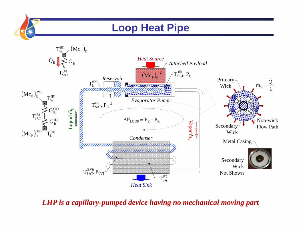
Loop Heat Pipe
(E)T
EG
(E)WT
EQ
EPMc
Heat Source
(E)
Attached Payload
( )SATT
(R)WT
)W(RPMc
Evaporator Pump
ReservoirTSAT, PE
(E)
TL(IN)
EPMc
1
VQm
2Q
PrimaryWick
(R)SATT
(L)RG
(W)RG
W
(R) )W(
Evaporator Pump
VapoLiqu
id m
L
TSAT, PR(R)
PLOOP PE PR Non-wickFlow PathSecondary
Wi k(R)LT )W(
RPMcCondenser
or mV
Wick
Metal Casing
Secondary
Heat Sink
TSAT, PLVI(LVI)
TSAT(C)
Secondary Wick
Not Shown
LHP is a capillary-pumped device having no mechanical moving part
LHP Linear Stability Theory
Is LHP state x capable of reaching steady state xSS ?
tk
ke(t) Axx SS2050
/K)
TSINK = 10oC and TAMB = +23oC
x
k
ke(t) Axx SS
10
12
14
16
18
25
30
35
40
45
mpe
ratu
re (o C
)
ance
1/R
LHP
(W/
1/RLHPPoint 1xSS x xSS
2
4
6
8
10
5
10
15
20
25
Satu
ratio
n Te
m
herm
al C
ondu
cta
TSAT
Point 3
02 4
000 100 200 300 400 500 600 700
ThPower Input (Watts)
Point 3
)CRIT(
)L(RP
)W(RP
)E(W 11McMcT
Instability Criterion for Low-Frequency/High-Amplitude Oscillations
)CRIT(LFHAINPEPSSE GQcMcQ
LHP Linear Stability Theory
Is LHP state x capable of reaching steady state xSS ?
tk
ke(t) Axx SS2050
/K)
TSINK = 10oC and TAMB = +23oC
x
k
ke(t) Axx SS
10
12
14
16
18
25
30
35
40
45
mpe
ratu
re (o C
)
ance
1/R
LHP
(W/
1/RLHPPoint 1
TW(E)
QIN/GE
xSS x xSS
2
4
6
8
10
5
10
15
20
25
Satu
ratio
n Te
m
herm
al C
ondu
cta
TSAT
Point 3
02 4
000 100 200 300 400 500 600 700
ThPower Input (Watts)
Point 3
)CRIT(
)L(RP
)W(RP
)E(W 11McMcT
Instability Criterion for Low-Frequency/High-Amplitude Oscillations
)CRIT(LFHAINPEPSSE GQcMcQ
Criterion for Low Frequency Oscillations
)CRIT(
LFHAINPEP
)L(RP
)W(RP
SSE
)E(W
G1
Q1
cMcMcMc
QT
For Unstable LHP Operation:ESS
0e
Zone 1 Zone 2Zone 3
(E)WT
0
SSIN
)E(W
QT
nduc
tanc
e
13
)CRIT(G/1ture
or C
on
)3(INQ)1(
INQ
for large attachedLFHAG/1
Tem
pera
t for large attached thermal mass
Criterion for Low Frequency Oscillations
)CRIT(
LFHAINPEP
)L(RP
)W(RP
SSE
)E(W
G1
Q1
cMcMcMc
QT
For Unstable LHP Operation:ESS
0e
Zone 1 Zone 2Zone 3
(E)WT
0
SSIN
)E(W
QT
nduc
tanc
e
13
)CRIT(G/1ture
or C
on
)3(INQ)1(
INQ
for decreasingLFHAG/1
Tem
pera
t for decreasingthermal mass
Criterion for Low Frequency Oscillations
)CRIT(
LFHAINPEP
)L(RP
)W(RP
SSE
)E(W
G1
Q1
cMcMcMc
QT
For Unstable LHP Operation:ESS
0e
Zone 1 Zone 2Zone 3
(E)WT
0
SSIN
)E(W
QT
nduc
tanc
e
13
)CRIT(G/1ture
or C
on
)3(INQ)1(
INQ
for decreasingLFHAG/1
Tem
pera
t for decreasingthermal mass
Criterion for Low Frequency Oscillations
)CRIT(
LFHAINPEP
)L(RP
)W(RP
SSE
)E(W
G1
Q1
cMcMcMc
QT
For Unstable LHP Operation:ESS
0e
Zone 1 Zone 2Zone 3
(E)WT
0
SSIN
)E(W
QT
nduc
tanc
e
13
)CRIT(G/1ture
or C
on
)3(INQ)1(
INQ
for decreasingLFHAG/1
Tem
pera
t for decreasingthermal mass
JPL TES Loop Heat Pipe
(o C)
20
30
40
20
25
30
Wat
ts)
JPL TES/LHP EDU 12/08/1999 TSINK = 10oC
TC8
TC6
Tem
pera
ture
(
0
10
20
10
15
20
Hea
t Inp
ut (W
TC8
TC23 TC24
10
Elapsed Time (hours)0 1 2 3 4 5 6 7 8 9 10
H
0
5TC31TC32
20
With Large Attached Thermal MassTests with Heater Block
Rodriguez, J. and A. Na-Nakornpanom, “Investigation of Transient Temperature Oscillations of a Propylene Loop Heat Pipe,” Paper No. 01ICES-74, International Conference on Environmental Sciences (ICES), 2001.
JPL TES Loop Heat Pipe
Evaporator P i Wi k C i /S ddl 1st Wi k d A h d Th l M
Dimensions and Properties of LHP Components
Primary Wick Casing/Saddle, 1st Wick, and Attached Thermal Mass Material: Sintered Powder Nickel Attached Thermal Mass: 9,080J/K Outer Diameter: 24.21mm (0.950”) Thermal Mass-to-Vapor Inner Diameter: 9.525mm (0.375”) Conductance GE: 8.16 W/K Active Length: 0.1524m (6”) Saddle: 7.62cm x 15.24cm x 1.91cm Al 6061 Max. Pore Radius: 1.2m Vapor Grooves Permeability: 4.0x10⁻¹⁴m2 Number of Channels: 4 Effective Conductivity: 7.8W/m-K Hydraulic Diameter: 0.05” Transport LinesTransport Lines Vapor Line Liquid Line Outer Diameter: 5.54mm Outer Diameter: 5.54mm Wall Thickness: 0.508mm Wall Thickness: 0.508mm Length: 1.0m Length: 1.2264m (incl. bayonet) C d R iCondenser Reservoir Number of Parallel Passes 1 Outer Diameter: 43.94mm Heat Exchanger Tubing Wall Thickness: 2.20mm Inner Diameter: 3.99mm Active Length: 0.08023m Length: 3.81m (200”) Thermal Mass (McP)R: 190J/K
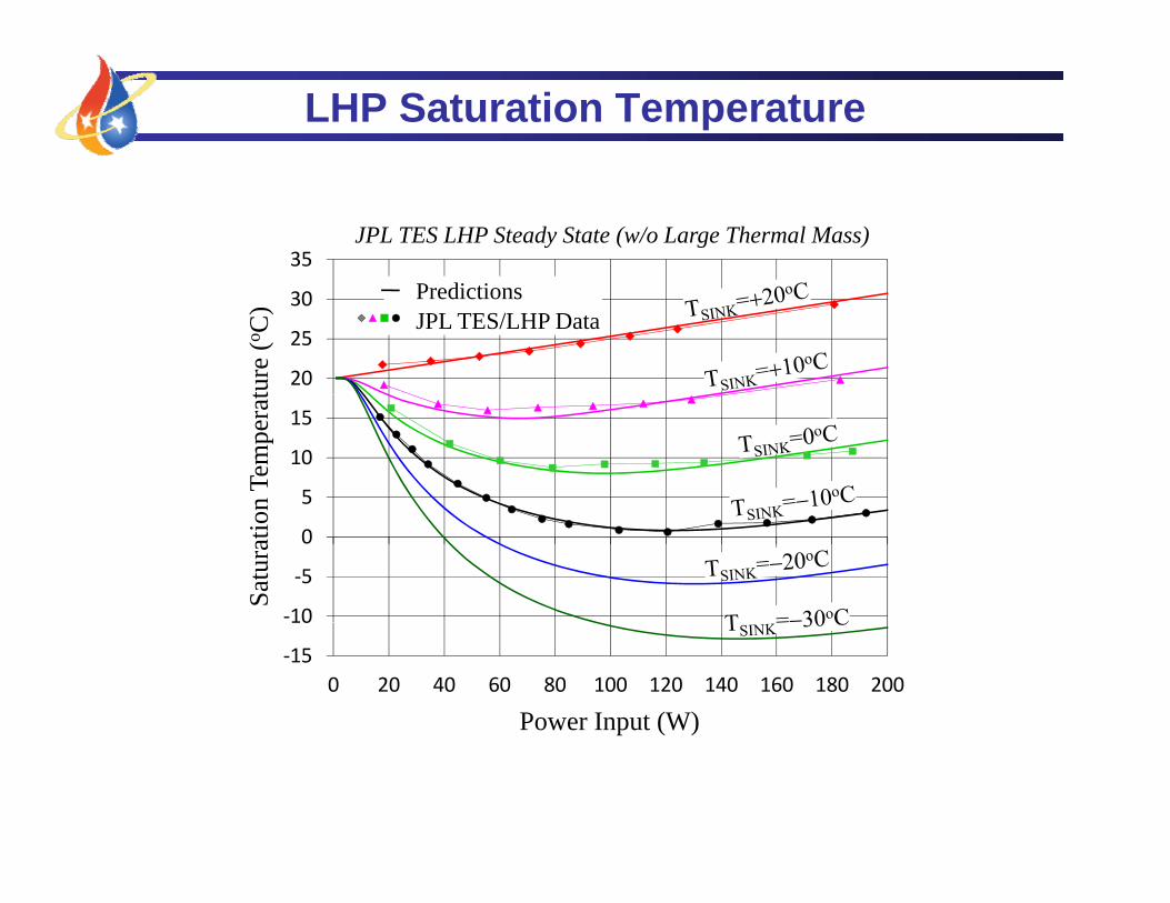
35JPL TES LHP Steady State (w/o Large Thermal Mass)
20
25
30at
ure
(o C) Predictions
JPL TES/LHP Data
5
10
15
on T
empe
ra
‐10
‐5
0
Satu
ratio
‐150 20 40 60 80 100 120 140 160 180 200
Power Input (W)
LHP Saturation Temperature
35JPL TES LHP Steady State (w/o Large Thermal Mass)
20
25
30
ture
(o C) Predictions
JPL TES/LHP Data
5
10
15
n Te
mpe
rat
‐10
‐5
0
Satu
ratio
n
‐15
10
0 20 40 60 80 100 120 140 160 180 200
Power Input (W)
Thermal Mass Temperature
30JPL TES LHP Steady State (w/o Large Thermal Mass)
20
25
ratu
re (o C
)
15
20
ass T
empe
r
5
10
Ther
mal
M
00 20 40 60 80 100 120
T
Power Input (W)
Predicted Instability Map
80
90JPL TES LHP
W)
60
70
80
wer
Inpu
t (W
40
50 Predicted Region of Instability
Pow
10
20
30
Sink Temperature (oC)30 25 20 15 10 5 0 5 10 150
10
20
Sink Temperature (oC)
Predictions vs. Test Data
Test Without Oscillations
JPL TES LHP
80
90W
)
60
70
80
wer
Inpu
t (W
40
50 Predicted Region of Instability
Pow
10
20
30
Sink Temperature (oC)30 25 20 15 10 5 0 5 10 150
10
20
Sink Temperature (oC)
Predictions vs. Test Data
80
90Test Without Oscillations
JPL TES LHPW
)
60
70
80Test With Oscillations
wer
Inpu
t (W
40
50 Predicted Region of Instability
Pow
10
20
30
Sink Temperature (oC)30 25 20 15 10 5 0 5 10 150
10
20
Sink Temperature (oC)
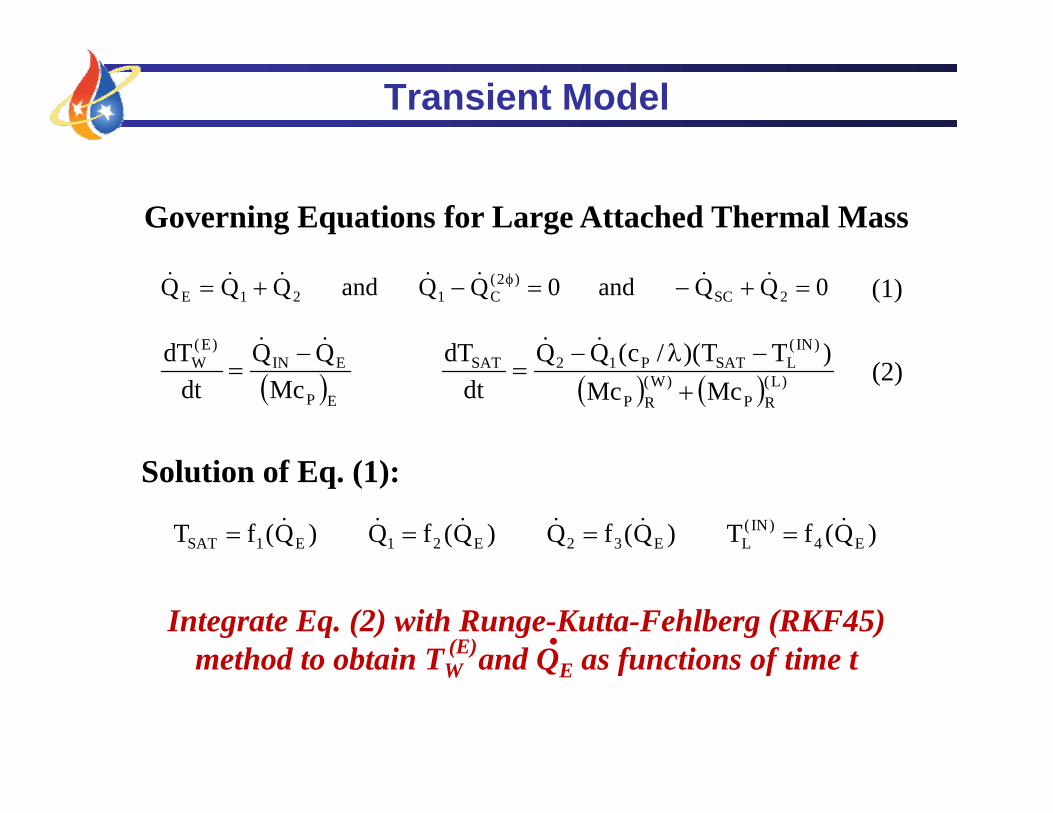
Transient Model
Governing Equations for Large Attached Thermal Mass
)IN()E( )TT)(/c(QQdTQQdT
0 QQ and 0 QQ and QQQ 2SC)2(
C121E (1)
)L(RP
)W(RP
LSATP12SAT
EP
EINW
McMc)TT)(/c(QQ
dtdT
McQQ
dtdT
(2)
Solution of Eq. (1):
)Q(fT )Q(fQ )Q(fQ )Q(fT E4)IN(
LE32E21E1SAT
Integrate Eq. (2) with Runge-Kutta-Fehlberg (RKF45)method to obtain T and Q as functions of time t(E) .method to obtain TW and QE as functions of time t
Predictions vs. Test Data)
20 01/24/2000 TSINK = 10oC
Power Input
Pow
er (W
)
15Evaporator
(Data)
e (o C
) or P
10
empe
ratu
re
5
i
Reservoir(Data)
Evaporator
Te
0 1 2 3 4 5 60
Reservoir(Model)
p(Model)
Elapsed Time (hours)
Predictions vs. Test Datae
(o C)
15
20
15W/20W/30W Power Input TSINK = 10oCEvaporator
(Model)
25
Heat Input
25
30
35
ut (W
)
e (o C
)
20
30
02/14/2000 TSINK = 10oC
Reservoir(Data)
Evaporator(Data)
40
Heat Input
30
40
50
ut (W
)
Tem
pera
ture
5
10
15
15
20
25
Pow
er In
pu
Tem
pera
tur
0
10
20 ( )
10
20
30
Pow
er In
pu
0 5 10 15 20 25 300
Elapsed Time (hours)
Reservoir(Model) 10
0 4 8 12 16 20 2410
Elapsed Time (hours)28
0
360Prediction for TSINK=30oC
35
riod
(min
utes
)
180
240
300 TES/EDU Data for TSINK=30oC
Prediction for TSINK=20oC
TES/EDU Data for TSINK=20oC
Prediction for TSINK=10oC
TES/EDU Data for TSINK=10oC
P di i f T 0 C Am
plitu
de (o C
)20
25
30
Osc
illat
ion
Per
60
120
180 Prediction for TSINK=0oC
TES/EDU Data for TSINK=0oC
Peak
-to-P
eak
A
5
10
15
0 10 20 30 40 50 60 70 800
Power Input (W)
P 5
Power Input (W)0 10 20 30 40 50 60 70 80
0
Conclusion / Summary
• LHP Linear Stability Theory– low-frequency/high-amplitude oscillations are caused by large
thermal mass ratio between evaporator and reservoir– unstable range of power input is between those of two
extrema (Points 1 & 2) of TW vs. QIN curve, i.e. dependent on (E) .
environmental heating of liquid line and reservoir– theory is limited to single-pass condenser LHPs
• Theory Verification• Theory Verification– model predictions agreed very well with JPL TES test data– unfortunately, test data from only one LHP are available
• Path Forward– continue with verification when additional data available– add multiple parallel evaporators/condensers to theory