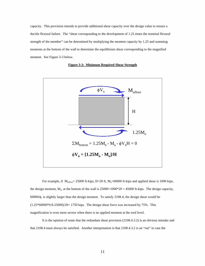
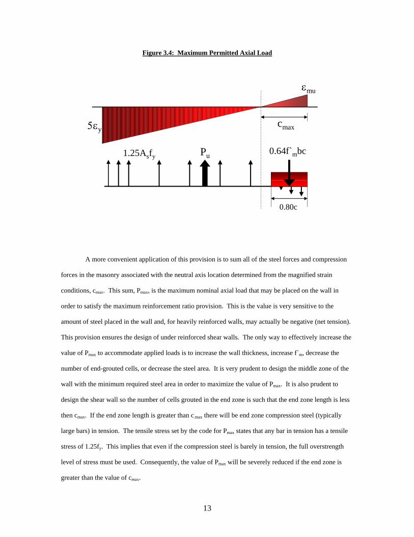
1 VERIFICATION OF MASONRY DESIGN SOFTWARE NATIONAL CONCRETE MASONRY INSTITUTE PHASE II A Special Project Report Presented to: The College of Engineering and Science Clemson University In Partial Fulfillment Of the Requirements for the Degree: Master of Science Civil Engineering Prepared by: Bryan Thomas Lechner Johnny Lee McElreath December 16, 2002 Special Project Advisor: Dr. Russell H. Brown
Transcript
1
VERIFICATION OF MASONRY DESIGN SOFTWARE
NATIONAL CONCRETE MASONRY INSTITUTE
PHASE II
A Special Project Report
Presented to:
The College of Engineering and Science
Clemson University
In Partial Fulfillment
Of the Requirements for the Degree:
Master of Science
Civil Engineering
Prepared by:
Bryan Thomas Lechner
Johnny Lee McElreath
December 16, 2002
Special Project Advisor: Dr. Russell H. Brown
2
ABSTRACT
The National Concrete Masonry Society (NCMA) in conjunction with Dr. James K. Nelson and
Dr. Russell H. Brown have developed software for the design of concrete masonry structures. The Phase I
software, completed in December 1999, included design modules for the design of out-of-plane concrete
masonry walls and concrete masonry and reinforced concrete lintels using Allowable Stress Design
methodology and the requirements of the Masonry Society Joint Committee (MSJC) building code (MSJC-
95, MSJC-99). The BETA version of this software was completed in August 1999. Its accuracy was
verified by Robert Eric Burgess in his Special Project Report, Verification of Masonry Design Software
Developed for the National Concrete Masonry Association1.
This report presents the verification of Phase II of the NCMA Masonry Design Software (Version
3.1.1.2). The Phase II version has the capability to design both out-of-plane and in-plane walls and lintels
using Allowable Stress or Strength Design methodologies. The software has also been improved to include
five different code requirements: MSJC 1995, MSJC 1999, MSJC 1999 with the IBC 2000 provisions, IBC
2000, and MSJC 2002. The accuracy of the new design modules and codes was verified by comparing
design results generated by the NCMA Software with results generated from independent algorithms
developed in MathCAD 8.0 and MathCAD 2001 specifically for this Special Project. Oliver Himbert
completed an Interim Report2 in May presenting his work on Phase II verification. Mr. Himbert developed
several MathCAD 7.0 verification files but was unable to verify the NCMA Software before graduation.
This Special Project is a continuation of the work presented in the Interim Report. New
MathCAD 8.0 verification files were independently developed to verify each of the design modules and the
existing MathCAD 7.0 files were modified to reflect the changes in the design codes. At the time this
report was written, the BETA version of the Phase II NCMA Software was still in development. As a
result, the verification is not complete for every design module and code. The verification that has been
completed has returned very positive results.
3
TABLE OF CONTENTS 1.0 INTRODUCTION ........................................................................................................ 1 1.1 Purpose.......................................................................................................................... 1 1.2 NCMA Software Phase II ............................................................................................. 2
ck+1=(cnew + ck)/2 Neutral axis location for new time step
This iteration was copied nine times sequentially to converge on the actual value of c. The nine
cycles provides convergence to within one hundredth of an inch. The moment capacity is determined by
summing moments about the center of the wall using the neutral axis location determined from iteration.
The percentage moment utilization, the factor used to verify the critical section, is then determined by
dividing the critical design moment by the moment capacity.
%Mutil = |Mu*100|/Mcap.
The sliding φ factor calculation, iteration for the neutral axis location, moment capacity
determination, and percentage moment utilization calculation are then repeated for each of the 22 load
combinations and again for the 44 sets of load combinations corresponding to the design loads immediately
above and below the critical section.
The shear capacity is determined for each load combination using the unfactored design loads, φ =
0.8, and the factored shear force, Vu (see 3.1.2.4 of this report for detailed discussion of unfactored loads in
shear capacities). The shear resistance due to masonry, Vm, is calculated and if Vu/φ >Vm the difference, Vs
= (Vu/φ – Vm) is resisted by shear steel. The shear capacity is φ times lesser of either Vm + Vs or Vnmax, the
maximum shear capacity. If shear steel is required to develop the capacity to resist the design shear, the
area of shear steel corresponding to a spacing of 24 inches is determined for comparison with the NCMA
Software. The percentage shear utilization is determined from a similar equation:
%Vutil = |Vu*100|/Vcap
The calculation of shear capacity, the area of steel and the percentage moment utilization is then repeated
for all 22 load combinations.
32
3.3.3.1 Verification Procedure
The largest percentage utilization for flexure and shear and the corresponding load combinations
are determined from the array of percentage utilizations. Mathcad then creates two tables for verification
purposes. The first table consists of the values needed for the verification of the flexural and axial design
loads and capacities of the wall. The following values are tabulated for each load combination: Pu, Mu, Pmax,
Mcap, %Mutil (λ-.01), %Mutil, %Mutil(λ+.01), and Critical section check. The critical section check consists of an
algorithm that verifies %Mutil (λ-.01) < %Mutil > %Mutil(λ+.01) for each load combination. If the NCMA
Software has determined the location of the critical section correctly, “yes” appears under the column
heading, if not, “no” will appear. The second table consists of the value needed for the verification of the
shear design loads and capacities. The following values are tabulated for each load combination: Pu, Vu,
Vcap, %Vutil, Vs, and Av(24”). Two examples of the output tables are displayed in Figures 3.7 and 3.8.
The values in the two Mathcad files represent the critical design loads, capacities and load
combinations for the input parameters displayed at the top of the two tables. The values from the two
tables were then input into an excel spreadsheet for comparison verses the values obtained from the NCMA
Software. The critical design axial load, moment and shear were compared for each load combination.
For the critical load case for flexure, the controlling load case, moment capacity, Pmax, φ, and the
percentage moment utilization were compared against the NCMA Software output. The critical load case
check was also included to communicate that the critical location was determined correctly. For the critical
load case for shear, the controlling load combination, the shear capacity, Vs, Av/s, and the percent
utilization were compared.
To ensure the NCMA Software generated interaction diagrams are plotting the design loads for
each combination correctly, the interaction diagram for each verification example was printed and
compared with the design values in the Mathcad tables.
The verification tables demonstrate that the load side design module for in-plane strength design
in the NCMA Software is calculating the design loads, critical section and capacities correctly. The load
modification factor is default at 0.5 for live load and 0.7 for snow load. When the verification in this
section was initiated the load modification factors in the Mathcad file were 0.5 and 0.2, respectively. The
33
difference in the snow load factor caused slight error in the design axial loads and moments determined
from load combination 6, 1.2D+E+f1L+f2S, the only load combination with f2 included.
The verification is in Appendix A-3.
34
Figure 3-7: Flexural and Axial Load Critical Section Design Forces
Fully Grouted Shear Wall Design Summary (Strength):Axial Lateral Moment
f m 1.5 103.= psi f y 6 104.= psi Loadkips( ) kip( ) kip in( )
Dead P D 120.628= xxxx M d 0=E m 1.35 106.= psi E s 2.9 107.= psi
Live P L 60= xxxx M l 0=
t 10= in A se 0.6= in2 Live Roof P Lr 14= xxxx M lr 0=
Snow P S 16= xxxx M s 0=L 360= in n g 8= cells
Rain P R 18= xxxx M r 0=
H 12= ft A sm 0.11= in2 Soil xxxx V H 20= M h 0=
Fluid xxxx V F 50= M f 0=s 72= in
Wind xxxx V W 90= M w 30000=
Earthquake xxxx V E 260= M e 37000=
LC %util.control ".9D + E + 1.6H"= P max 446.019= kipsLoad Combinations & % Utilization of Moment Capacity:
Load P u M u M capacity %Utiliztion %Utilization %Utilization Critical sectioncheckCombination
kips( ) in kip.( ) in kip.( ) λ .01 0.01= λ 0= λ 0.01 0.01=
1. 1.4D: P 1 169= M 1 0= M cap1 100406= %Util M1i 0.000= %Util M1 0.000= %Util M1j 0.000= c 1 "yes"=
2. 1.4(D+F): P 2 169= M 2 10080= M cap2 100406= %Util M2i 10.039= %Util M2 10.039= %Util M2j 9.942= c 2 "yes"=
3a. 1.2D+1.6L+.5Lr: P 3a 248= M 3a 0= M cap3a 108447= %Util M3ai 0.000= %Util M3a 0.000= %Util M3aj 0.000= c 3a "yes"=
3b. 1.2D+1.6L+.5S: P 3b 249= M 3b 0= M cap3b 108547= %Util M3bi 0.000= %Util M3b 0.000= %Util M3bj 0.000= c 3b "yes"=
3c. 1.2D+1.6L+.5R: P 3c 250= M 3c 0= M cap3c 108646= %Util M3ci 0.000= %Util M3c 0.000= %Util M3cj 0.000= c 3c "yes"=
3d. 1.2(D+F)+1.6(L+H)+.5Lr:P 3d 248= M 3d 13248= M cap3d 108447= %Util M3di 12.216= %Util M3d 12.216= %Util M3dj 12.097= c 3d "yes"=
3e. 1.2(D+F)+1.6(L+H)+.5S: P 3e 249= M 3e 13248= M cap3e 108547= %Util M3ei 12.205= %Util M3e 12.205= %Util M3ej 12.086= c 3e "yes"=
3f. 1.2(D+F)+1.6(L+H)+.5R: P 3f 250= M 3f 13248= M cap3f 108646= %Util M3fi 12.194= %Util M3f 12.194= %Util M3fj 12.074= c 3f "yes"=
4a. 1.2D+1.6Lr+f1L: P 4a 197= M 4a 0= M cap4a 103325= %Util M4ai 0.000= %Util M4a 0.000= %Util M4aj 0.000= c 4a "yes"=
4b. 1.2D+1.6Lr+.8W: P 4b 167= M 4b 34368= M cap4b 100226= %Util M4bi 34.290= %Util M4b 34.290= %Util M4bj 34.196= c 4b "yes"=
4c. 1.2D+1.6S+f1L: P 4c 200= M 4c 0= M cap4c 103653= %Util M4ci 0.000= %Util M4c 0.000= %Util M4cj 0.000= c 4c "yes"=
4d. 1.2D+1.6S+.8W: P 4d 170= M 4d 34368= M cap4d 100559= %Util M4di 34.177= %Util M4d 34.177= %Util M4dj 34.083= c 4d "yes"=
4e. 1.2D+1.6R+f1L: P 4e 204= M 4e 0= M cap4e 103981= %Util M4ei 0.000= %Util M4e 0.000= %Util M4ej 0.000= c 4e "yes"=
4f. 1.2D+1.6R+.8W: P 4f 174= M 4f 34368= M cap4f 100891= %Util M4fi 34.065= %Util M4f 34.065= %Util M4fj 33.970= c 4f "yes"=
5a. 1.2D+1.6W+f1L+.5Lr: P 5a 182= M 5a 68736= M cap5a 101739= %Util M5ai 67.561= %Util M5a 67.561= %Util M5aj 67.374= c 5a "yes"=
5b. 1.2D+1.6W+f1L+.5S: P 5b 183= M 5b 68736= M cap5b 101843= %Util M5bi 67.492= %Util M5b 67.492= %Util M5bj 67.306= c 5b "yes"=
5c. 1.2D+1.6W+f1L+.5R: P 5c 184= M 5c 68736= M cap5c 101946= %Util M5ci 67.424= %Util M5c 67.424= %Util M5cj 67.237= c 5c "yes"=
6. 1.2D+E+f1L+f2S: P 6 186= M 6 74440= M cap6 102173= %Util M6i 72.857= %Util M6 72.857= %Util M6j 72.508= c 6 "yes"=
7a. .9D+E: P 7a 109= M 7a 74440= M cap7a 94077= %Util M7ai 79.127= %Util M7a 79.127= %Util M7aj 78.745= c 7a "yes"=
7b. .9D+1.6W: P 7b 109= M 7b 68736= M cap7b 94077= %Util M7bi 73.064= %Util M7b 73.064= %Util M7bj 72.859= c 7b "yes"=
7c. .9D+E+1.6H: P 7c 109= M 7c 79048= M cap7c 94077= %Util M7ci 84.025= %Util M7c 84.025= %Util M7cj 83.596= c 7c "yes"=
7d. .9D+1.6(W+H) P 7d 109= M 7d 73344= M cap7d 94077= %Util M7di 77.962= %Util M7d 77.962= %Util M7dj 77.709= c 7d "yes"=
φ 7a 0.80805=
35
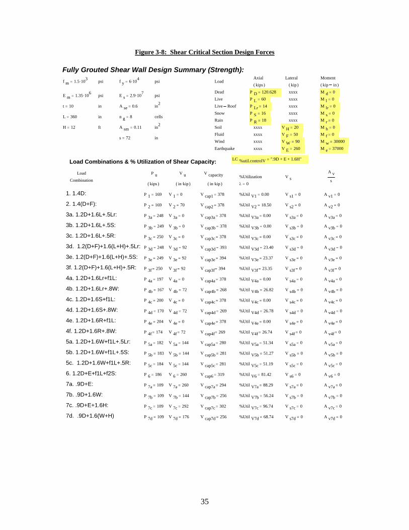
Figure 3-8: Shear Critical Section Design Forces
Fully Grouted Shear Wall Design Summary (Strength):Axial Lateral Moment
f m 1.5 103.= psi f y 6 104.= psi Loadkips( ) kip( ) kip in( )
Dead P D 120.628= xxxx M d 0=E m 1.35 106.= psi E s 2.9 107.= psi
Live P L 60= xxxx M l 0=
t 10= in A se 0.6= in2 Live Roof P Lr 14= xxxx M lr 0=
Snow P S 16= xxxx M s 0=L 360= in n g 8= cells
Rain P R 18= xxxx M r 0=
H 12= ft A sm 0.11= in2 Soil xxxx V H 20= M h 0=
Fluid xxxx V F 50= M f 0=s 72= in
Wind xxxx V W 90= M w 30000=
Earthquake xxxx V E 260= M e 37000=
LC %util.controlV ".9D + E + 1.6H"=Load Combinations & % Utilization of Shear Capacity:
Load P u V u V capacity %Utilization V sA v
sCombinationkips( ) in kip.( ) in kip.( ) λ 0=
1. 1.4D: P 1 169= V 1 0= V cap1 378= %Util V1 0.00= V s1 0= A v1 0=
2. 1.4(D+F): P 2 169= V 2 70= V cap2 378= %Util V2 18.50= V s2 0= A v2 0=
3a. 1.2D+1.6L+.5Lr: P 3a 248= V 3a 0= V cap3a 378= %Util V3a 0.00= V s3a 0= A v3a 0=
3b. 1.2D+1.6L+.5S: P 3b 249= V 3b 0= V cap3b 378= %Util V3b 0.00= V s3b 0= A v3b 0=
3c. 1.2D+1.6L+.5R: P 3c 250= V 3c 0= V cap3c 378= %Util V3c 0.00= V s3c 0= A v3c 0=
3d. 1.2(D+F)+1.6(L+H)+.5Lr: P 3d 248= V 3d 92= V cap3d 393= %Util V3d 23.40= V s3d 0= A v3d 0=
3e. 1.2(D+F)+1.6(L+H)+.5S: P 3e 249= V 3e 92= V cap3e 394= %Util V3e 23.37= V s3e 0= A v3e 0=
3f. 1.2(D+F)+1.6(L+H)+.5R: P 3f 250= V 3f 92= V cap3f 394= %Util V3f 23.35= V s3f 0= A v3f 0=
4a. 1.2D+1.6Lr+f1L: P 4a 197= V 4a 0= V cap4a 378= %Util V4a 0.00= V s4a 0= A v4a 0=
4b. 1.2D+1.6Lr+.8W: P 4b 167= V 4b 72= V cap4b 268= %Util V4b 26.82= V s4b 0= A v4b 0=
4c. 1.2D+1.6S+f1L: P 4c 200= V 4c 0= V cap4c 378= %Util V4c 0.00= V s4c 0= A v4c 0=
4d. 1.2D+1.6S+.8W: P 4d 170= V 4d 72= V cap4d 269= %Util V4d 26.78= V s4d 0= A v4d 0=
4e. 1.2D+1.6R+f1L: P 4e 204= V 4e 0= V cap4e 378= %Util V4e 0.00= V s4e 0= A v4e 0=
4f. 1.2D+1.6R+.8W: P 4f 174= V 4f 72= V cap4f 269= %Util V4f 26.74= V s4f 0= A v4f 0=
5a. 1.2D+1.6W+f1L+.5Lr: P 5a 182= V 5a 144= V cap5a 280= %Util V5a 51.34= V s5a 0= A v5a 0=
5b. 1.2D+1.6W+f1L+.5S: P 5b 183= V 5b 144= V cap5b 281= %Util V5b 51.27= V s5b 0= A v5b 0=
5c. 1.2D+1.6W+f1L+.5R: P 5c 184= V 5c 144= V cap5c 281= %Util V5c 51.19= V s5c 0= A v5c 0=
6. 1.2D+E+f1L+f2S: P 6 186= V 6 260= V cap6 319= %Util V6 81.42= V s6 0= A v6 0=
7a. .9D+E: P 7a 109= V 7a 260= V cap7a 294= %Util V7a 88.29= V s7a 0= A v7a 0=
7b. .9D+1.6W: P 7b 109= V 7b 144= V cap7b 256= %Util V7b 56.24= V s7b 0= A v7b 0=
7c. .9D+E+1.6H: P 7c 109= V 7c 292= V cap7c 302= %Util V7c 96.74= V s7c 0= A v7c 0=
7d. .9D+1.6(W+H) P 7d 109= V 7d 176= V cap7d 256= %Util V7d 68.74= V s7d 0= A v7d 0=
36
4.0 IN-PLANE (SHEAR WALL) ALLOWABLE STRESS DESIGN
4.1 Reinforced Masonry
4.1.1 Description A full description Allowable Stress Design of fully and partially grouted in-plane walls can be
found in Verification of the National Concrete Masonry Association Masonry Design Software (Phase II)
An Interim Report2 by Oliver Himbert.
4.1.2 Code Interpretation Specific problems or concerns regarding the code interpretation for Allowable Stress Design of
shear walls can be found in Verification of the National Concrete Masonry Association Masonry Design
Software (Phase II) An Interim Report2.
4.1.3 Mathcad Verification file Commentary regarding the Mathcad verification file (In-plane ASD PG.mcd) can be found in
Verification of the National Concrete Masonry Association Masonry Design Software (Phase II) An Interim
Report2 and in Appendix C.a of this report. Johnny McElreath completed further verification on reinforced
masonry using allowable stress design. This Verification work included the 1999 MSJC code (1999 MSJC
MSJC In-Plane.mcd) and the 2000 IBC code (2000 IBC In-Plane.mcd) and can be found in Appendix C.b
of this report.
4.1.3.1 Verification Procedure
Brian Lechner’s Verification Procedure:
Although the Mathcad verification file was completed by Mr. Himbert, the verification was never
completed. Verification of the flexural and axial load capacity of reinforced shear walls was completed by
comparing the axial load and moment capacity for different values of kd, the neutral axis depth. This
process was facilitated by making use of the temporary debugging table in the NCMA Software design
calculation output, which displays the moment and axial load capacities for every 50th value of kd in the
interaction diagram. Critical values of the neutral axis depth, kd, and the respective capacities were easily
37
chosen from the table and input into the MS Excel verification spreadsheet. The values of the neutral axis
depth chosen were then input directly into the Mathcad ASD in-plane verification file and the resulting
capacities were input into the verification spreadsheet for comparison.
This process was repeated for many different section configurations to ensure all potential for
error in the deisgn algorithms has been exercised. The wall thickness, shear wall length, masonry
compressive stress, steel yield stress, middle zone steel area and spacing, end zone steel area, and the
number of grouted cells in the end zone were systematically varied to verify that all of the algorithms for
the resistance side of the shear wall module is accurate. Fully grouted cases were also run by setting the
grout spacing to 8-in and allowing the steel spacing to vary, as with the partially grouted cases.
Verification was completed by observing the percent error between the NCMA Software and the Mathcad
verification file for axial load and moment capacity. All percent errors greater than 0.1% were investigated
and amended before verification was deemed complete.
In order to properly verify the shear capacity algorithms, the M/Vd ratio had to be manually
adjusted by changing the input moment and shear force magnitudes. Additionally, the shear force was
intentionally increased to levels where steel would be required to resist the shear steel. When M/Vd is
greater than one, Fmax = 80-45M/Vd when steel is not needed and Fmax = 120 – 45 M/Vd when steel is
required. When M/Vd is less than 1, Fmax is 35 psi when steel is not needed and 75 psi when steel is
needed. The M/Vd ratio and the applied shear force were adjusted to ensure every situation was exercised.
Verification was completed by comparing the Allowable shear stress for different values of M/Vd and V.
The area of steel required if the shear stress was higher that the allowable masonry shear stress was also
compared. The actual shear stress in the shear wall was determined by using the code equation, even for
partially grouted walls (the code equation is in violation of mechanics for walls other than fully grouted).
When solving for shear stress in partially grouted walls using principles of mechanics the results are
significantly higher than what the code equation equations determine.
The verification is found in Appendix A-4.a.
38
Johnny McElreath’s Verification Procedure:
Verification of the reinforced ASD in-plane design for the 1999 MSJC code and the 2000 IBC
code was completed in a similar manner as the reinforced strength design verifications. The verification of
the axial load, moment and shear capacities were completed, for each allowable stress design code, by
performing various problems in the NCMA software and comparing them to problems with the same
parameters executed in the MathCAD algorithms. Comparisons were completed for all CMU thicknesses
(i.e. 6-inch, 8-inch, 10-inch and 12-inch) available in the NCMA software. Each problem that was
executed varied by changing one or many of the following parameters: loading patterns, reinforcement
sizes, end zone grout spacing, middle zone reinforcing spacing, wall length and wall height. Once the
problems were performed in both NCMA and MathCAD, values for the axial load, moment, shear, shear
stress, moment capacity, allowable shear stress, required shear steel per foot, and the value of maximum
allowable axial load were compared at the controlling load combination. MS Excel was used to store these
data values and compute the percentage error for each value. All percent errors greater than 0.1% were
investigated and amended before verification was deemed complete. Verification Results are in Appendix
A-4.b.
39
4.2 Unreinforced Masonry
4.2.1 Description The unreinforced in-plane design module for Allowable Stress Design is significantly different
from the unreinforced Strength Design counterpart. The configuration is the same; fully grouted end zones
with an ungrouted or partially grouted middle zone. The difference lies in the allowable tension stress and
the stacked bond walls design requirements.
4.2.2 Code Interpretation 4.2.2.1 Allowable Tensile Stress The MSJC code does not allow tension stress at any location in
unreinforced shear walls. This implies that the eccentricity of the applied loads, M/P, must be equal to or
less than the kern eccentricity. The kern eccentricity is defined as the largest distance from the neutral axis
an axial load may be applied without causing tension stress in the extreme tensile fiber. It can be determine
by dividing the section modulus, S, by the cross sectional area of the wall. For solid, rectangular walls this
value is t/6.
4.2.2.2 Maximum Axial Load The maximum axial load permitted on an unreinforced shear wall
is determined from a modified version of the Euler bucking equation. The value of axial load determined is
reduced by a value depended on the eccentricity of the axial load. This eccentricity is in reference to the
out-of-plane eccentricity.
4.2.2.3 Stacked Bond Construction The MSJC does not distinguish between running bond and
stacked bond construction for the determination of the flexural and axial load capacities. However, there
are different equations for the allowable shear stresses of stacked bond construction. Again, open end units
may not be used for design in the NCMA Software.
4.2.2.4 Shear Stress Determination The MSJC provides guidance for determining the design
vertical shear stress caused by flexure, VQ/Ib, but does not provide an equation for the horizontal shear
stress, V/Ae. Both shear stress determination methods have been included for consistency even though the
code does not specifically require the determination of horizontal shear stress.
40
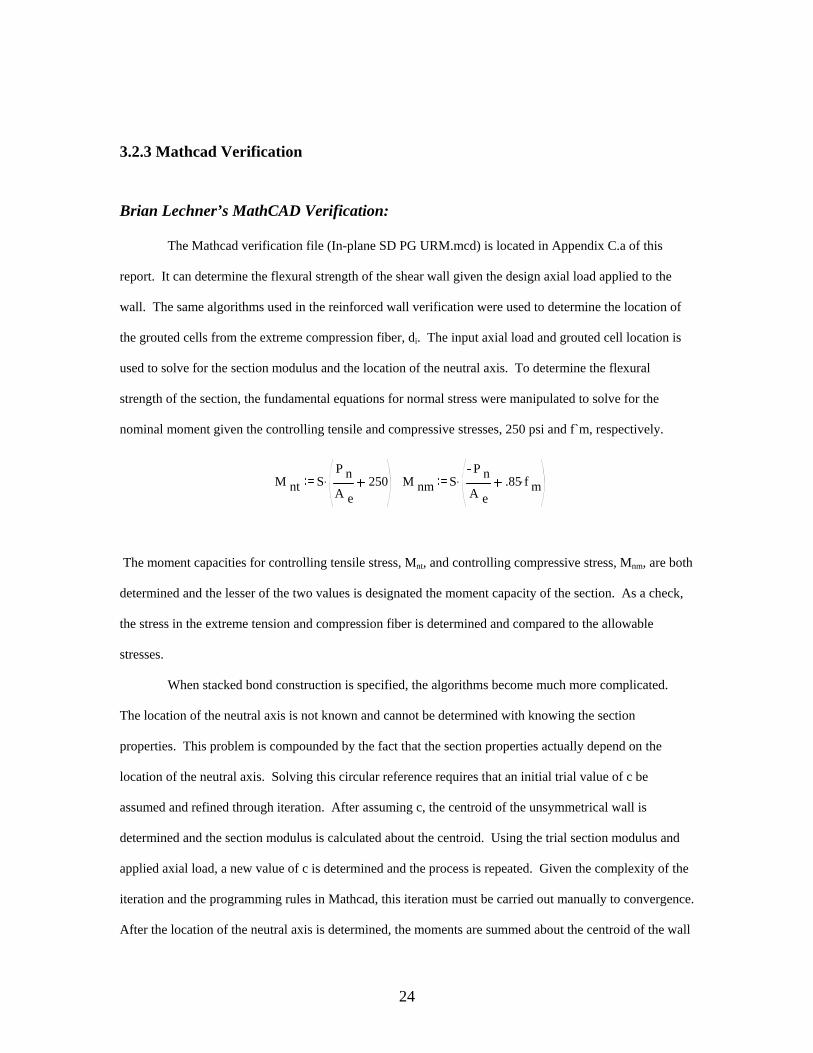
4.2.3 Mathcad Verification file Brian Lechner’s MathCAD Verification:
The Mathcad verification file, [In-plane ASD PG URM].mcd, is included in Appendix C.a of this
report. It has the capability of determining the axial load and moment capacities based on the input axial
load and it can determine if the input shear force is within the allowable shear stress for the section
properties and conditions. The section property input is identical to that for the Strength Design
verification file except the input loads are unfactored. Mathcad determines the location of the grouted cells
using algorithms copied from the other in-plane programs and then determines the section modulus, area
and radius of gyration for the cross section. Two moment capacities are determined and the lesser of the
two capacities is designated the moment capacity of the wall. The tension controlled capacity is simply
determined by multiplying the axial load by the kern eccentricity, P(S/A). The compression controls
capacity is determined by manipulating the equation for normal stress and solving for the moment
associated with f`m/3, the allowable compression stress. The design moment is then checked against the
unity equation, which will only control under large axial loads.
Finally, the maximum permitted axial load is determined from the Euler equation and the input
out-of-plane eccentricity. The horizontal shear stress, V/A, and the vertical shear stress, VQ/Ib, are
checked against the allowable shear stresses determined from the empirical code equations.
Johnny McElreath’s MathCAD Verification
The MathCAD verification files for fully grouted unreinforced shear walls, which include the
design codes for 1999 MSJC ASD (1999 MSJC ASD In-Plane URM.mcd) and 2000 IBC ASD (2000 IBC
ASD In-Plane URM.mcd) can be found in Appendix C.b. These verification files were developed in
MathCAD 2001 using Brian Lechner’s files. These files have the capability of computing the factored
design loads based on the user defined service loads. The nominal axial, moment and shear capacities were
determined in the same manner as described above in Mr. Lechner’s verification work for unreinforced
strength design, but these capacities were determined for each load combination. The controlling capacity
was chosen based on the highest percent utilization from all load combinations as describe in section 3.3.3
of this report. The controlling capacities were displayed for verification purposes.
41
4.2.3.1 Verification Procedure
Brian Lechner’s Verification Procedure:
Verification of the unreinforced shear wall design module was conducted in a different manner
than for reinforced masonry module. Instead of varying the neutral axis depth and determining the
associated axial load and moment capacity, the applied axial load was varied and the and the associated
moment capacity was determined. The axial load was varied in a way that ensured an equal fraction of
tension controlled walls and compression controlled walls were verified. The maximum axial load was
also compared to the NCMA Software generated values although the NCMA Software does not have an
input for the out of plane eccentricity. The maximum axial load provision could not be properly verified
without knowing what eccentricity the NCMA Software was using.
The properties of the shear walls were varied in order to exercise all of the algorithms in the
design module. Ungrouted, partially grouted and fully grouted walls were checked.
Verification is found in Appendix A-5.
Johnny McElreath’s Verification Procedure:
Verification of the unreinforced ASD in-plane design for the 1999 MSJC code and the 2000 IBC
code was completed in a similar manner as the reinforced strength design verifications. The verification of
the axial load, moment and shear capacities were completed, for each allowable stress design code, by
performing various problems in the NCMA software and comparing them to problems with the same
parameters executed in the MathCAD algorithms. Comparisons were completed for all CMU thicknesses
(i.e. 6-inch, 8-inch, 10-inch and 12-inch) available in the NCMA software. Each problem that was
executed varied by changing one or many of the following parameters: loading patterns, end zone grout
spacing, middle zone grout spacing, wall length and wall height. Once the problems were performed in
both NCMA and MathCAD, values for the axial load, moment, shear, shear stress, moment capacity,
allowable shear stress, and the value of maximum allowable axial load were compared at the controlling
load combination. MS Excel was used to store these data values and compute the percentage error for each
42
value. All percent errors greater than 0.1% were investigated and amended before verification was deemed
complete. Verification Results are in Appendix A-5.
4.3 Critical Section Design Forces
4.3.1 Description A full description of Allowable Stress Design load side module for fully grouted in-plane walls
according to the MSJC 1999 with IBC 2000 provisions can be found in Verification of the National
Concrete Masonry Association Masonry Design Software (Phase II) An Interim Report2 by Oliver Himbert
4.3.2 Code Interpretation Specific problems or concerns regarding the code interpretation for Allowable Stress Design of
shear walls can be found in Verification of the National Concrete Masonry Association Masonry Design
Software (Phase II) An Interim Report2
4.3.3 Mathcad Verification file Commentary regarding the Mathcad verification file can be found in Verification of the National
Concrete Masonry Association Masonry Design Software (Phase II) An Interim Report2.
43
5.0 OUT-OF-PLANE STRENGTH DESIGN
5.1 Reinforced masonry
5.1.1 Description The out of plane design module for the NCMA Software is remarkably different than the out-of-
plane ASD modules. Aside from the obvious differences in design philosophy between Ultimate Strength
Design and Allowable Stress design, the Strength Design module requires the iterative analysis of p-delta
effects for slenderness consideration and the area of steel severely limits the axial load permitted on the
wall. These provisions and limitations are discussed in detail in 5.1.2, Code Interpretation. The design
philosophy and the previously mentioned differences provide for extremely ductile out-of-plane wall
designs using the IBC 2000 code.
The design input for fully grouted and partially grouted out-of-plane walls is identical to the input
used in Phase I. The only difference lies in the input of the critical section design forces, which must be
factored ultimate loads. Also unique to the Strength Design input is the requirement for unfactored critical
design load input. The shear capacity determination uses unfactored loads to increase conservatism. The
unfactored loads are discussed in more detail in section 5.1.2: Code Interpretation.
The resistance side of the out-of-plane design module does not have the capability to determine
the design moment from p-delta analysis. It is assumed that the designer will enter critical design loads
based on p-delta analysis completed independently. However, the NCMA Software does have the ability to
run p-delta analysis from the load side design module. The designer can enter unfactored applied loads in
the “Load Data” input tab and the NCMA software will automatically run p-delta analysis on every load
combination and determine the critical loads to be used for the resistance side design. For more on this
capability see Section 5.3: Critical Section Design Forces.
The user can choose between three different support conditions, simple, cantilever and propped
cantilever. When designing from the resistance side algorithms, this will not in any way change the
capacity of the wall. The resistance side design module is completely independent of the support
conditions. The capacities are based on the applied forces and the section properties of the wall. When
44
operating from the load side, the support conditions will have a significant impact on the critical design
section loads.
The configuration of the wall also remains unchanged from Phase I. The designer may choose to
design unreinforced or reinforced walls and he or she has the option to fully or partially grout either. If the
wall is partially grouted, the input spacing is used as the center-to-center grout spacing and as the steel
spacing if reinforcement is used. When a fully grouted wall is chosen, the spacing only refers to the
spacing between the bars of steel. The user may input the bar size used for design, but the NCMA software
will also determine the minimum required area of steel for the critical design loads input. However, the
section capacities plotted on the interaction diagram and displayed in the Design Calculations will refer to
the input area of steel.
The NCMA software also has the capability to design walls with eccentric steel, where the value
of d is less than or greater than half the wall thickness. The software will plot the interaction diagrams for
both the strong and weak axis and independently determine the value of Pmax for both directions (Pmax is
dependent on d). However the capacities determined for the Design Calculation output are dependent only
on the input value of d, which is not necessarily the controlling direction.
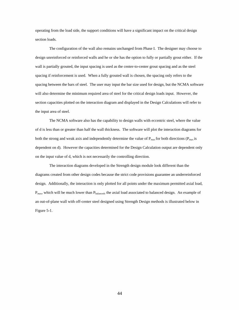
The interaction diagrams developed in the Strength design module look different than the
diagrams created from other design codes because the strict code provisions guarantee an underreinforced
design. Additionally, the interaction is only plotted for all points under the maximum permitted axial load,
Pmax, which will be much lower than Pbalanced, the axial load associated to balanced design. An example of
an out-of-plane wall with off-center steel designed using Strength Design methods is illustrated below in
Figure 5-1.
45
Figure 5-1: Interaction Diagram for Out-of-Plane Wall (SDM)
In Strength Design, section capacities are determined by setting the strain in the extreme
compressive fiber of masonry to -0.0025 and, based on the neutral axis depth, the steel tension force and
the compression force in the grouted masonry core and in the face shell are determined. Depending in the
depth of the neutral axis, the geometry of masonry in compression will change. For most designs the depth
of the neutral axis will be less than the face shell thickness so the area in compression will be rectangular.
The grouted cores will not contribute to the capacity of the wall. When the depth of the neutral axis is
greater than the face shell thickness, the area in compression becomes a T-section and spacing of the
grouted core will figure into the capacity of the wall. When determining the compression force in the
grouted core for T-sections, NCMA uses the actual grouted cell length, bw, as specified for ASTM C90
block. As a result of the Pmax provision for Strength Design, the majority of designs will have neutral axis
depths that are less than the face shell thickness. A simplified free body diagram of shear wall using
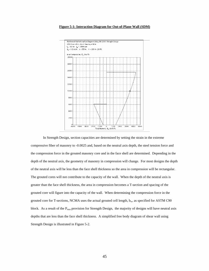
Strength Design is illustrated in Figure 5-2.
46
The shear capacity of the section is determined from the wall cross section and the critical section
design forces. Shear steel cannot be used in out-of-plane wall so the full design shear must be resisted by
the shear capacity of the masonry, Vm.
Figure 5-2: Out-of-Plane Section Mechanics
εmu = .0025
c
dεs
AsfyPu
a=0.85c
0.85f`m (IBC 2000) 0.80f’m (MSJC 2002)
0.85f`mab (IBC 2000) 0.80f`mab (MSJC 2002)
47
5.1.2 Code Interpretation Strength Design Out-of-plane walls were plagued by the same code interpretation problems that
afflicted shear wall design. Many of the provisions are common to both out-of-plane and in-plane design
and discussed in entirety in Section 3.1.2.
5.1.2.1 Maximum Reinforcement Ratio (2108.9.2.13.1 IBC 2000 and 3.2.3.5 MSJC 2002) This
provision sets severe guidelines on the maximum steel percentage permitted out-of-plane walls. The code
requires the neutral axis location, c`, is determined based on a critical steel tensile strain of 1.3 times the
yield strain, and that the tensile stress in the steel is fixed at 1.25 times the yield stress of steel, regardless of
the strain in the steel. The compression zone is based on a Whitney stress block equal to
0.8*cmax*0.8*f`m*b. The provision is illustrated graphically below in Figure 5.3.
Figure 5.3: Maximum Permitted Axial Load
εmu = .0025
Cmax
d1.3εy
1.25AsfyPu
a=0.80c
0.80f`m
0.64f`mcb
Pu=Pmax=0.64f`mcmaxb - 1.25Asfy
A more convenient application of this provision is to sum the steel force and compression force
associated with the neutral axis depth, cmax. This sum, Pmax, is the maximum ultimate axial load that may
48
be placed on the wall in order to satisfy the maximum reinforcement ratio provision. This is the value is
very sensitive to the area of steel placed in the wall and, for heavily reinforced walls, may actually be
negative (net tension). This provision ensures the design of underreinforced walls. The only way to
effectively increase the value of Pmax to accommodate applied loads is to increase the wall thickness,
increase f`m, or decrease the steel area. The requirement usually places the neutral axis depth in the face
shell. This provision was verified by comparing Pmax between the NCMA Software and the Mathcad
software.
Pmax is calculated in the same manner for the MSJC 2002 code, which is listed under the provision
3.2.3.5, Maximum Reinforcement Percentages, but the compression steel is neglected in this computation.
It should also be noted that the maximum axial load in MSJC 2002 strength design is based upon
unfactored gravity axial loads, which is not the case in IBC 2000 strength design. In the IBC code, Pmax is
based upon factored gravity axial loads. Finally, the sections 3.2.3.5.1 and 3.2.3.5.2 of the MSJC 2002
commentary state, “The unfactored gravity axial loads referred to in this provision are intended to be the
gravity components of the allowable stress design loading combinations that include earthquake from the
legally adopted building code.” This implies that the maximum axial load computed using the 3.2.3.5
provision under the MSJC 2002 strength design code only applies to load combination that include
earthquake and does not apply to load combinations that do not included earthquake. For this reason, the
NCMA Design Software (Version 3.1.1.2) will allow you into the design calculations page when the
unfactored axial loads exceed Pmax for all load combinations except the ones that include earthquake.
5.1.2.2 Design Strength
5.1.2.2.a (2108.9.4.4 IBC 2000) The design nominal moment strength, Mn, specified by the IBC 2000 code
provisions is in violation with the basic principles of mechanics and only applies to fully grouted walls
(walls with a rectangular compression zone) and walls with concentric steel. The code specified equations
are as follows:
Mn = Asefy(d-a/2) Eq: 21-36
Ase = As + Pu/fy Eq: 21-37
a = (Pu + Asfy)/0.85f`mb Eq: 21-38
49
Where Mn is the nominal flexural strength of the section, Ase is the effective area of steel, a is the depth of
the Whitney stress block, Pu is the factored ultimate axial load and b is the effective width of the section,
usually the steel spacing. The effective area of steel is a magnified value of steel area attributed to the
benefit of axial load. It effectively includes the axial load into the moment calculation. This can be
verified by substituting Ase into Equation 21-36. This yields Mn = Asfy(d-a/2) + Pu(d-a/2), which is the
flexural capacity of the cross section if moments are summed about the steel location, d.
The troubling aspect of this provision is that it violates mechanics. The nominal flexural strength,
Mn, is determined using a design level axial load, φPn. This does not yield the same results as determining
Mn using Pn and then multiplying by φ. When the nominal moment capacity is selected from an interaction
diagram using Pn, the capacity is much different than if the nominal moment capacity is selected using Pu,
which is 80 percent of Pn. Dependent on the slope of the interaction diagram, the difference can be
significant. See Figure 5-4 below.
Figure 5.4: IBC vs. Mechanics
P n
P u
M nM `n
N om in a l C ap ac ity
M `u M u
IB C 2 0 0 0 C ap ac ity
It is obvious that the intent of the provision was to determine a more conservative moment capacity, one
based on a smaller axial load. When Mn based on mechanics is plotted with Mn based on the IBC it is
evident that the results are not always conservative. The graph below (Figure 5-4) illustrates that the IBC
provisions for determining flexural capacity are non-conservative for axial loads slightly larger than Pbalanced
and for sections with net axial tension.
50
F ig u r e 5 -4 : M ech a n ics V s IB C 2 0 0 0
-50000.00
0.00
50000.00
100000.00
150000.00
200000.00
-50000 0 50000 100000 150000 200000 250000
M n o r M u (lb s -in)
Pn o
r Pu
(lbs)
P n - M ec hanic s
P n - IB C 2000
This does not seem to be a concern because the maximum reinforcement provision (see 5.1.2.1)
limits the axial load to levels below the balance point and walls should not be designed for net tension.
However, the problem encountered was whether to program equations that are in violation with mechanics
and only apply to fully grout walls with concentric steel, or to program correct equations but be in violation
of the IBC.
Ultimately, the code equations were altered to include eccentric steel and partially grouted walls
and the flexural capacity is based on the design level axial load, Pn, per IBC provisions. This applies to the
NCMA software and the Mathcad verification file.
5.1.2.2.b (3.2.5.4 MSJC 2000) The design nominal moment strength, Mn, specified by the MSJC 2002
code provisions is in violation with the basic principles of mechanics, as were the IBC equations, and only
applies to fully grouted walls (walls with a rectangular compression zone) and walls with concentric steel.
The code specified equations are as follows:
Mn = (Asfy + Pu)(d-a/2) Eq: 3-27
a = (Pu + Asfy)/0.80f`mb Eq: 3-28
Where Mn is the nominal flexural strength of the section, As is the effective area of steel, a is the depth of
the Whitney stress block, Pu is the factored ultimate axial load and b is the effective width of the section,
usually the steel spacing. The effective area of steel is a magnified value of steel area attributed to the
51
benefit of axial load. It effectively includes the axial load into the moment calculation. These equations
violate the principals of mechanics in the same manner as the IBC 2000 equations. Refer to section
5.1.2.2.a for an explanation of this violation.
5.1.2.3 Shear Design (2108.9.3.5 IBC 2000 and 3.2.4.1 MSJC 2002) These provisions, common for both
out-of-plane and in-plane walls, set forth requirements for the shear capacity in masonry walls. The
difference between in-plane and out-of-plane shear design is that out-of-plane walls must resist the design
shear forces with only the capacity of the masonry, Vm. Shear steel is not permitted in out-of-plane walls.
The maximum shear capacity, Vnmax, and the masonry capacity, Vm, are determined using unfactored load
combinations. A detailed commentary on this code provision, including the unfactored load combinations
is presented in Section 3.1.2.3: Shear Design.
5.1.2.4 Deflection Design (2108.9.4.6 IBC 2000 and 3.2.5.6 MSJC 2002) These provisions state that the
horizontal midheight deflection under service lateral and service axial (unfactored loads) shall be limited to
the following:
δ ≤ 0.007 h
Where δ, is the midheight deflection and h, is the effective height of the wall. The NCMA software does
not check this limitation, however the software does print what is called δmax, which is 0.007 multiplied the
effective height. A MathCAD file was developed to determine if this limitation was ever exceeded, and
after several problems were examined, it was concluded that this limitation never controls the deflection
design.
5.1.3 Mathcad Verification file Brian Lechner’s MathCAD Verification:
The Mathcad verification file developed for the resistance side of out-of-plane Strength Design,
Out-of-plane SD PG.mcd, is located in Appendix C.a. The program determines the flexural, axial and
shear capacity of an out-of-plane from the critical factored axial load, and the unfactored axial load,
moment and shear force. A copy of this program, Out-of-plane SD FG.mcd, has been slightly modified to
52
design fully grouted walls with variable steel spacing. When the steel is eccentric, both programs
simultaneously determine the axial and flexural capacities for the strong and weak axis.
The input for the out-of-plane strength design verification file includes the masonry properties, the
steel properties, the section properties including wall thickness, steel spacing, steel area and location,
height, and the applied loads; the factored axial load, and unfactored axial load, moment and shear force at
the critical section. The applied loads are input on a per linear foot basis. The section capacities are
computed for an effective section the width of the steel spacing. For consistency, the input loads are
increased by the ratio of the spacing to one foot, or δ. The final capacities are divided by this ratio to
express the capacities on a linear foot basis.
Depending on the section properties and factored axial load, the program first determines the
depth of the Whitney Stress block, a. If the value of a is greater than the face shell thickness, the
calculations for the moment capacity are determined using a T-section compression zone. The strong axis
nominal moment capacity is determined by summing moments about the center of the wall. The weak axis
is simply determined by summing moments about the center of the wall and using (h-d) in place of d. If d
is in the center of the wall both equations should yield the same value. The design level capacities are then
φMn, where φ is 0.80 for out-of-plane walls.
Pmax is determined twice, once for each axis. The weak axis value of d is much smaller so
consequently, the maximum axial load permitted will be much smaller as well. The procedure for
determining Pmax is detailed in Section 5.1.2.1.
Lastly, the shear capacity is determined using the unfactored loads. The design shear capacity is
taken as the lesser of Vnmax or Vm times φ=0.80. For detailed commentary on the shear determination see
Section 3.1.2.3.
Johnny McElreath’s MathCAD Verification
The MathCAD verification files developed for fully grouted reinforced out-of-plane design using
both a loads side and resistance side module, which include the design codes for 2000 IBC Strength (2000
IBC Strength Out of Plane.mcd) and 2002 MSJC Strength (2002 MSJC Strength Out of Plane.mcd), can be
found in Appendix C.b. These verification files were developed in MathCAD 2001 using Brian Lechner’s
53
files. The input for the out-of-plane strength design verification file includes the masonry properties, the
steel properties, the section properties including wall thickness, steel spacing, steel area and location,
height, critical section for moment (taken from NCMA), the deflection due to factored loads (taken from
NCMA) and the applied service loads.
The program first determines the moments, shears, and deflections for the wall (i.e. simple support
or cantilever), and the appropriate load factors are then applied to the axial loads, moments, shears and
deflections. From this point, the program determines the factored moment for the wall, for each load
combination, taking into account the effect of P-Delta (Note: Please refer to section 5.3.3 of this report to
see how the load side module was developed and how the P-Delta moment is computed). Once this
moment is computed the moment capacity is determined. The theoretically required steel area is also
computed at this point based on the moment with P-Delta. Finally, a summary of factored axial load,
moment, moment capacity is displayed for each load combination, and the controlling load case, point of
critical section, factored axial load, factored moment, moment capacity and displacement for the
controlling load case is displayed to ease in the verification process.
5.1.3.1 Verification Procedure
Brian Lechner’s Verification Procedure:
The out-of-plane Strength Design resistance side algorithms were verified by comparing the
design flexural capacity, Mu (in-lbs/ft), the depth of the Whitney Stress block, a, and the value of Pmax
(lbs/ft) at varying axial loads. The range of axial loads was carefully chosen to include the full range of
capacities. To accomplish this, the wall properties for the verification were input and the design was
calculated in Mathcad. The value of Pmax¸, which is independent of axial load, was noted. The range of
axial loads used for verification started at a value slightly smaller than Pmax and continued down past pure
bending to the axial load attributed to zero flexural capacity. The seven intermediate loads were evenly
distributed between. Therefore, the range of axial loads used in verification was different for each wall
thickness and for each verification problem. In order to test all the algorithms, all variables were isolated
for verification and all sources of error greater than 0.1% were investigated and amended. Several full
grout verification problems were run as well using the modified Mathcad file.
54
The shear capacity algorithms were tested in the same manner as they were for the in-plane
verification. The M/Vd ratio and the value of P were adjusted to induce the control of the different code
equations. The values of Vnmax, Vm, and Vu were compared to ensure the NCMA software was calculating
the correct values.
The verification is found in Appendix B-1.a.
Johnny McElreath’s Verification Procedure:
Verification of the reinforced out of plane strength design for the 2000 IBC and 2002 MSJC codes
was completed by performing various problems in the NCMA software and comparing them to problems
with the same parameters executed in the MathCAD algorithms. Comparisons were completed for all
CMU thicknesses (i.e. 6-inch, 8-inch, 10-inch and 12-inch) available in the NCMA software. Each
problem that was executed varied by changing one or many of the following parameters: loading patterns,
wall height, reinforcing size and spacing. Once the problems were performed in both NCMA and
MathCAD, values for the axial load, moment, moment capacity, deflection, theoretical area of steel and
critical section were compared at the controlling load combination. MS Excel was used to store these data
values and compute the percentage error for each value. All percent errors greater than 0.1% were
investigated. It should be noted that some values for moment capacity, deflection and critical section
exceed 0.1%. The excess error in the moment capacity and deflection can be attributed to the equation
used to compute the P-Delta deflection in MathCAD (Please refer to section 5.3.3). The critical section
error in excess of 0.1% was discovered to be a difference in the way NCMA and MathCAD rounded the
numbers. If the value for the critical section is examined closely, this error is negligible. Verification
Results are in Appendix B-1.b.
55
5.2 Unreinforced Masonry
5.2.1 Description Strength design of unreinforced masonry is very similar to Allowable Stress Design. Design is
controlled by a table containing allowable tension stress, termed the modulus of rupture, fr, that are
dependent on the mortar type and masonry wall. The unreinforced walls can be ungrouted, partially
grouted or fully grouted. The steel spacing input is used to specify the center to center grout spacing. The
wall may be constructed in running bond or stack bond but it cannot span horizontally between pilasters.
5.2.2 Code Interpretation 5.2.2.1 Stress in Masonry (2108.7.5 IBC 2000 and 3.1.7.2 MSJC 2002) Unreinforced out-of-plane walls
are permitted to carry tension stress. The “allowable” stress, termed the modulus of rupture, is dependent
on the bond type, grout type, mortar type and span direction. A table of these values is given in the IBC
Table 2108.7.5: Modulus of Rupture for Out-Of-Plane Bending and MSJC Table 3.1.7.2.1: Modulus of
Rupture. Instead of comparing the actual stress state of the masonry to these tables, the moment capacity
with no axial load assuming tension controls is determined by the following equation:
Mn = Mcr =Sfr
Where the nominal flexural capacity is the cracking moment, S is the section modulus, and fr is the
modulus of rupture pulled from Table 2108.7.5 for IBC strength design and Table 3.1.7.2.1 for MSJC
strength design.
The compression stress cannot exceed 0.85f`m for IBC strength design and 0.80f’m for MSJC
strength design.
5.2.2.2 Maximum Axial Load (2108.10.3 IBC 2000 and 3.3.3 MSJC 2002) The maximum axial load
provision that applied to reinforced shear walls obviously does not apply to unreinforced walls because of
the lack of steel. The maximum axial load provision for unreinforced out-of-plane walls is identical to the
provision for in-plane walls. See Section 3.2.2.2 for commentary.
56
5.2.2.3 Shear Capacity (2108.10.4.1 IBC 2000 and 3.3.4 MSJC 2002) Out-of-plane walls share the
same shear provisions as in-plane walls for unreinforced construction. The option to design with open-
ended units is not available for the out-of-plane module as well. Open-ended units cannot be used for
design.
.
5.2.3 Mathcad Verification file The Mathcad verification file for out-of-plane unreinforced resistance side verification, Out-of-
plane SD FG URM.mcd, is in Appendix C. The Mathcad verification file has the ability to determine the
axial, flexural and shear capacity for any type bond, grout or mortar. The flexural capacity of the wall is
based on the input axial load, Pu. The section properties, grout type and spacing, bond type, mortar type and
axial load are input and algorithms choose the correct modulus of rupture from an internal table of values
copied from IBC 2108.7.5. The section modulus and cross-sectional area are calculated from section tables
nested in the Mathcad file.
Two moment capacities are determined, one for tension controls and one for compression controls.
The lesser of the two capacities is the controlling capacity and is denoted the nominal flexural capacity of
the section. The two equations for nominal moment capacity were determined by manipulating the
fundamental equation for normal stress given the modulus of rupture, fr, and the compression stress,
0.85f`m.
Mnt = S(Pu/φAe + fr) Mnc = S(-Pu/φAe + 0.85f`m)
The design level capacity is determined by multiplying the controlling moment by φ (0.80).
Finally the maximum axial load and shear capacity is determined per the special requirements in Section
5.2.2.
5.2.3.1 Verification Procedure
Verification of the unreinforced out-of-plane design module was conducted by varying the applied
axial load and recording the associated moment capacity and neutral axis depth. Verification of the NCMA
unreinforced design module for Strength Design was completed by comparing the moment capacity
determined for the given axial load. The axial load was adjusted in a manner that ensured an equal fraction
57
of tension controlled walls and compression controlled walls were verified. The maximum axial load,
Pnmax, was also compared to the NCMA Software generated values.
The section properties, bond type, and mortar type were varied in order to exercise all of the
algorithms in the design module. Ungrouted, partially grouted and fully grouted walls were checked.
The six empirical equations for shear capacity were exercised by changing the grout type, and bond type.
The verification of unreinforced out-of-plane walls has not been completed as of December 14, 2001. It
will be located in Appendix B-2.
58
5.3 Critical Section Design Forces
5.3.1 Description The development of the load side algorithms for out-of-plane Strength Design has been one of the
most challenging aspects of the Special Project. The Phase II software includes the ability to conduct p-
delta analysis for the applied set of loads and determine the critical design moment, axial load, shear and
deflection for each of the 22 load combinations. This required that deflection equations be developed for
each of the load configurations for all three support conditions. This capability is the most remarkable
feature added to the Phase II load side design module.
The out-of-plane load side module for strength design has the capability of determining the critical
load combination for flexure and for shear given the applied loads, the support conditions, the height of the
wall and the IBC Strength Design load combinations. The manner in which the applied loads are “applied”
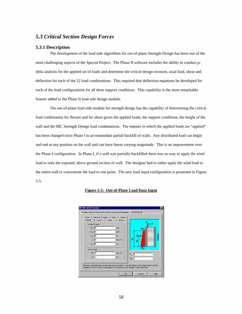
has been changed since Phase I to accommodate partial backfill of walls. Any distributed load can begin
and end at any position on the wall and can have linear varying magnitude. This is an improvement over
the Phase I configuration. In Phase I, if a wall was partially backfilled there was no way to apply the wind
load to only the exposed, above ground section of wall. The designer had to either apply the wind load to
the entire wall or concentrate the load to one point. The new load input configuration is presented in Figure
5-5.
Figure 5-5: Out-of-Plane Load Data Input
59
The NCMA software determines the design forces and critical section for each load combination
then chooses the most critical load case for design. The design axial load, Pu, moment, Mu, deflection ∆u
and shear, Vu, for the critical load case and section are then input into the resistance side module and
capacities are determined based on section properties. The critical load cases for flexure and shear are
output in the design calculations. The critical section for flexure and shear is denoted by the ratio x/H,
where x is measured from the bottom of the wall and H is the height of the wall.
5.3.2 Code Interpretation The majority of the interpretation for the out-of-plane design module was centered on the
requirement for p-delta analysis. The other two issues, load combinations and unfactored loads, are
common to both in-plane and out-of-plane and have been addressed in Section 3.3.2.
5.3.2.1 P-∆ Analysis (2108.9.4.4)
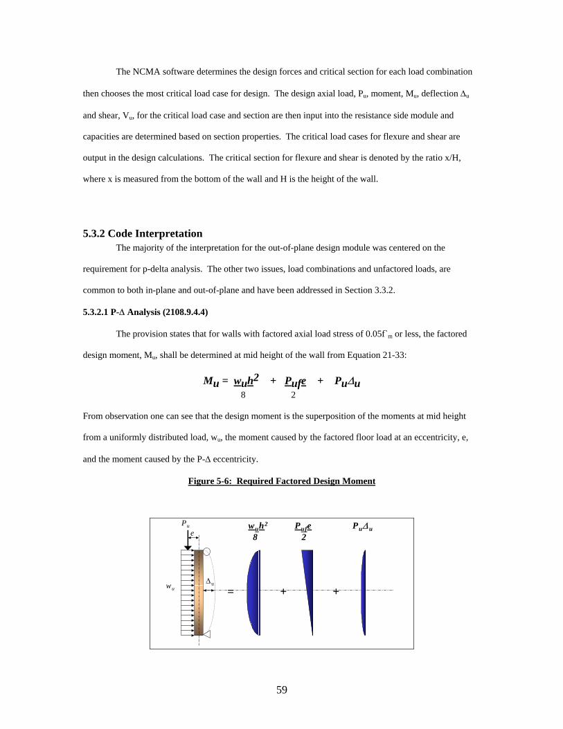
The provision states that for walls with factored axial load stress of 0.05f`m or less, the factored
design moment, Mu, shall be determined at mid height of the wall from Equation 21-33:
Mu = wuh2 + Pufe + Pu∆u 8 2
From observation one can see that the design moment is the superposition of the moments at mid height
from a uniformly distributed load, wu, the moment caused by the factored floor load at an eccentricity, e,
and the moment caused by the P-∆ eccentricity.
Figure 5-6: Required Factored Design Moment
wuh2 Pufe Pu∆ u8 2
+ +
Pue
wu∆u
=
60
The code equation is severely limited in its application. It assumes that the wall has simple
support end conditions, a uniformly distributed lateral load, and that the critical design section is located at
mid-height. The NCMA Software needs to model three different support conditions, varying load
conditions and consequently, and a critical section located somewhere other than mid-height. The IBC
equation surly will not satisfy these requirements. The code does offer some guidance, “[for] other support
and fixity conditions, moments and deflections shall be calculated using established principles of
mechanics” (IBC 2108.9.4.3).
One concern was the code approach to determining the mid-height deflection. The code provides
an equation for service load deflections but it does not specifically state that the equation can also be used
for factored load deflections. However, the range of applicability for the deflection equation is stated as
Mcr < Mser < Mn. This range will include Mu as it must be less than Mn to satisfy design requirements. If
Mu is substituted into Equation 21-40 and 21-41, the following equations for deflection at mid-height
result:
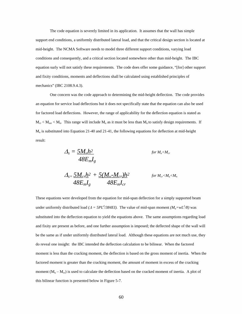
∆s = 5Muh2 for Mu<Mcr
48EmIg
∆s= 5Mcrh2 + 5(Mu-Mcr)h2 for Mcr<Mu<Mn
48EmIg 48EmIcr
These equations were developed from the equation for mid-span deflection for a simply supported beam
under uniformly distributed load (∆ = 5PL4/384EI). The value of mid-span moment (Mu=wL2/8) was
substituted into the deflection equation to yield the equations above. The same assumptions regarding load
and fixity are present as before, and one further assumption is imposed; the deflected shape of the wall will
be the same as if under uniformly distributed lateral load. Although these equations are not much use, they
do reveal one insight: the IBC intended the deflection calculation to be bilinear. When the factored
moment is less than the cracking moment, the deflection is based on the gross moment of inertia. When the
factored moment is greater than the cracking moment, the amount of moment in excess of the cracking
moment (Mu – Mcr) is used to calculate the deflection based on the cracked moment of inertia. A plot of
this bilinear function is presented below in Figure 5-7.
61
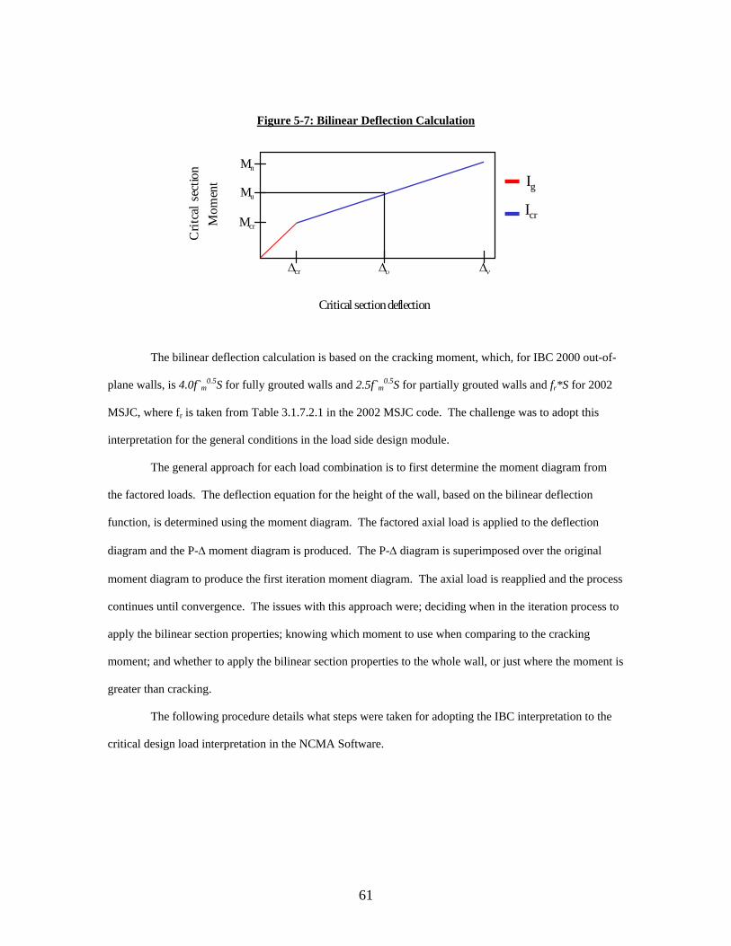
Figure 5-7: Bilinear Deflection Calculation
Mn
Mu
Mcr
∆cr ∆υ ∆ν
Crit
cal s
ectio
nM
omen
t
Critical sectiondeflection
Ig
Icr
The bilinear deflection calculation is based on the cracking moment, which, for IBC 2000 out-of-
plane walls, is 4.0f`m0.5S for fully grouted walls and 2.5f`m
0.5S for partially grouted walls and fr*S for 2002
MSJC, where fr is taken from Table 3.1.7.2.1 in the 2002 MSJC code. The challenge was to adopt this
interpretation for the general conditions in the load side design module.
The general approach for each load combination is to first determine the moment diagram from
the factored loads. The deflection equation for the height of the wall, based on the bilinear deflection
function, is determined using the moment diagram. The factored axial load is applied to the deflection
diagram and the P-∆ moment diagram is produced. The P-∆ diagram is superimposed over the original
moment diagram to produce the first iteration moment diagram. The axial load is reapplied and the process
continues until convergence. The issues with this approach were; deciding when in the iteration process to
apply the bilinear section properties; knowing which moment to use when comparing to the cracking
moment; and whether to apply the bilinear section properties to the whole wall, or just where the moment is
greater than cracking.
The following procedure details what steps were taken for adopting the IBC interpretation to the
critical design load interpretation in the NCMA Software.
62
Critical section location and moment determination1 For each input load and support conditions selected determine M(x) and ∆(x) (elastic curve
based on Ig)
2 Determine Mu(i)(x) and ∆u(i)(x) for each load combination, e.g.,Mu(7a)(x) = 0.9MD(x) + 1.6MW(x)∆u(7a)(x) = 0.9∆D(x) + 1.6∆W(x) <== Ig
3 Define: α = Ig/Icr β(ι)(x) = Mcr/Mu(i)(x)
4 The P-∆ iteration is conducted for every load combination using the moment-area therom and superposition. The deflection equation for time step k..n, ∆u(k+1)(x), and the P-∆ moment diagram are calculated using the following equations:
5 The deflection equations for the remaining time steps are determined from the total moment diagram at each time step from the moment area theorem and:
bilinear I if [Mu(k+1)(x)] > Mcr and Ig otherwise
6. Steps 4 and 5 are iterated n times until convergence7. The total design moment equation and deflection equation are determined from:
Mu(n)(x) for k=1..n
∆u(n)(x) for k=1..n8. The critcal location for design is determined and the associated design loads and
delfcetion (Pu, Mu, and ∆u) are used for design.
∆u(0)(x)
Mu(x)
∆u(1)(x)
Pu
Mu(1)(x)
∆u(2)(x)
Pu
∆u(3)(x)
Pu
∆u(4)(x)
Pu
Mu(2)(x) Mu(3)(x)
Graphical Determination of Critical Design Loads and Deflection
∆u(n)(x)
Mu(n)(x)
63
5.3.3 Mathcad Verification file The Mathcad program for the load side verification of the NCMA software has four principle
objectives:
Verify that the NCMA Software is using the proper load combinations by determining
the design loads and deflections at the critical section for each load combination
Verify that the NCMA Software is converging on the correct critical design moment and
deflection for the controlling load combination
Verify that the NCMA Software is determining the critical section by ensuring the values
of percentage moment utilization immediately above and below the critical section are
lower than the critical percentage moment utilization
Verify that the NCMA Software is determining the proper flexural, shear and axial load
capacities for the critical design loads.
The verification file was developed to determine the moment, axial load and shear capacity for a
fully grouted reinforced masonry wall. The same masonry, steel and section property input used for the
reinforced, partially grouted resistance side verification file was used in this program. Input for the nine
possible applied loads and the two variable load modification factors, f1 and f2, were added to accommodate
the requirements for load verification. Several values from the NCMA output are input as well. The
location of the wall that the NCMA Software “thinks” is critical is input as λ, the NCMA Software critical
flexural section (x/H), and ψ, the critical shear section (x/H). Also, the critical magnified deflection from
P-∆ analysis for the controlling load case is input in order to verify the accuracy of the P-∆. Using the
input applied loads, the design level moment, Mu, shear, Vu, and axial load, Pu, are determined at the
critical location for each of the load combinations listed in Table 3-2. Using an identical set of load
combinations, Mathcad also determines the design moment, shear and axial load at (λ-.01) and (λ+.01),
points immediately below and above the critical section. These values are used to determine if the section
is in fact critical. Mathcad also determines a fourth set of unfactored design loads at the critical section
64
using the unfactored load combinations tabulated in Table 3-1. The unfactored loads are used to determine
the shear capacity corresponding to each load combination.
The verification of the P-∆ analysis is approached indirectly. Mathcad determines the factored
design moment at the critical section, Mu(λ), and using the moment area theorem, determine the factored
deflection, ∆u(λ), for each load combination based on the gross moment of inertia. The final magnified
deflection input from NCMA is then used to complete one interaction of P-∆ analysis at the critical section.
If the deflection is correct, the moment and deflection will converge precisely after one iteration for the
critical load case (convergence will not occur for the other 21 load cases because the input deflection is
specific to the critical load case). The critical moment and deflection can then be used for design purposes.
See the outlined procedure below.
Mathcad Verification of the NCMA P-∆ Algorithms1. The factored deflection, ∆u(λ), for each load combination is determined at the critcal location, λ
2. The deflection due to the bilinear section properties is determined for each load case:∆u(act)(λ) = ∆u(λ) if Mu(λ)< Mcr
3. The moment due to the first P-∆ iteration is determined at the critical locationMP-∆(λ)= Pu∆u(act)(λ)
4. The final moment from P-∆ analysis is determined by superimposing the factored moment at λwith the first iteration P-∆ moment magnified by the NCMA deflection to initial deflection ratio. This moment is the design moment after P-∆ analysis and will have the same magnitude as the design moment from the NCMA software
Mu(final) = Mu+ MP-∆(∆uNCMA/∆u(act)) = MuNCMA
5. The final deflection after P-D analysis is then back-calculated∆u(final) = (Mu(final) - Mu)/Pu
6. Check for convergence:∆u(fianl)Pu = Mu(final) Must be equal
After the final design moment and deflections are determined, the ultimate moment capacity,
Mucap, corresponding to the factored axial load is determined for each load combination. The IBC
equations for the resistance side design discussed in Section 5.1.2.1 were used to determine the nominal
moment capacity based on the critical design level axial load.
The percentage moment utilization, the factor used to verify the critical section, is then determined
by dividing the critical design moment by the moment capacity.
65
%Mutil = |Mu*100|/Mcap.
The moment capacity determination and percentage moment utilization calculation are then
repeated for each of the 22 load combinations and again for the 44 sets of load combinations corresponding
to the design loads immediately above and below the critical section.
Pmax, dependent on the steel area, is solved once for the input section properties. It is equilibrium
axial load for a cross section with strain in the masonry of .0025, strain in the steel of 1.3 times the yield
strain, constant steel tension force of 1.25Asfy, a compression zone bounded by 0.8ch, and a compression
stress of 0.8f`m. The development of the Pmax algorithms is discussed in detail in section 3.1.2.3 of this
report.
The shear capacity is determined for each load combination using the unfactored design loads, φ =
0.8, and the factored shear force, Vu (see 3.1.2.4 of this report for detailed discussion of unfactored loads in
shear capacities). The shear resistance due to masonry, Vm, is calculated. The shear capacity is φ times
lesser of either Vm or Vnmax, the maximum allowable shear capacity. The percentage shear utilization is
determined from a similar equation:
%Vutil = |Vu*100|/Vcap
The calculation of shear capacity and the percentage moment utilization is then repeated for all 22 load
combinations.
3.3.3.2 Verification Procedure
The largest percentage utilization for flexure and shear and the corresponding load combinations
are determined from the array of percentage utilizations. Refer to section 5.1.3 of this report to clearly
understand how the verifications were completed for this portion.
66
6.0 OUT-OF-PLANE ALLOWABLE STRESS DESIGN
6.1 Reinforced Masonry All discussion, commentary, and verification for the resistance side module for reinforced out-of-
plane walls, full and partial grout, designed using Allowable Stress Design can be found in Verification of
Masonry Design Software Developed for the National Concrete Masonry Association1.
Note: This does not include verification and commentary associated with the currently released
MSJC 2002 design code.
6.2 Unreinforced Masonry All discussion, commentary, and verification for the resistance side module for unreinforced out-
of-plane walls, full, partial, and ungrouted, designed using Allowable Stress Design can be found in
Verification of Masonry Design Software Developed for the National Concrete Masonry Association1.
Note: This does not include verification and commentary associated with the currently released
MSJC 2002 design code.
6.3 Critical Section Design Forces All discussion, commentary, and verification for the load side module for reinforced and
unreinforced out-of-plane walls, full, partial, and ungrouted, designed using Allowable Stress Design can
be found in Verification of Masonry Design Software Developed for the National Concrete Masonry
Association1.
Note: This verification was conducted before the load input data and associated moment and shear
equations have been changed in Phase II. It is recommended the MSJC 1999 load combinations be verified
once again. Also, the MSJC 1999 with IBC 2000 provisions load combinations and the new MSJC 2002
load combinations have not been verified as well. The Mathcad files related have not been changed to
reflect the new data input. The load combinations for the new MSJC 2002 code need to be included in the
new verification as well.
67
7.0 LINTEL DESIGN
7.1 Lintel Allowable Stress Design
7.1.1 Description Lintels are structural members that span horizontally in openings in concrete masonry walls.
These lintels are there to support the weight of the wall above the opening in addition to any dead and live
loads. These additional live loads can come in the form of uniform or concentrated loads. Lintels can be
designed from a variety of materials. The NCMA software has the capability to design reinforced concrete
masonry or precast concrete lintels. Lintels are generally designed as a simply supported beam, and the
NCMA software is restricted to designing lintels in this format.
Lintels can support various loads: uniform, triangular or concentrated. As mentioned, these loads
can come in the form of dead and live loads. NCMA has the ability to design lintels using the self weight
of the lintel, self weight of the wall above the lintel, dead, live, roof, rain and snow loads. These loads can
be input as a uniform, joist or concentrated loads. The weight of the wall above the lintel can be designed
as a uniform load or as an equilateral triangular load. This triangular load is called arching action. This
arching action occurs when the masonry wall is laid in a running bond, the wall height above the lintel is
tall enough to form a 45 degree triangle, the wall height above the arch is at least 8-inches and the
minimum end bearing is maintained. The NCMA software does have the capability to use arching action.
Lintels designed using an allowable stress procedure restrict the stresses caused by service loads
from exceeding the maximum allowable stresses. The flexural compressive and tensile stresses acting in
lintels are determined using basic structural mechanics. The masonry is assumed to resist the compressive
forces in the lintel, and the tensile stresses are assumed to be resisted by the reinforcing steel. Lintels must
also be designed to resist the shear forces. Theses forces are typically the largest at the point the lintel
bears on the wall at either end of the opening in the wall. Lintels are typically designed so that the
maximum applied shear stress in limited to the allowable shear strength of the masonry, otherwise if this is
not done, shear reinforcement must be used in the lintel. The NCMA software does not have the capability
to include shear reinforcement in the lintel.
68
7.1.2 Code Interpretation The NCMA software allows for two different codes to be used for the allowable stress design,
1999/2002 MSJC ASD and 2000 IBC ASD. (2.1.1.1 MSJC 1999 and 2.1.2 MSJC 2002) The 1999/2002
MSJC ASD codes require load to be combined using the following:
Dr. Nelson, Dr. Brown and the author communicated problems in the NCMA software or
questions about interpretation of the code over email in order to keep a digital record of the verification
process. This has proven invaluable to the verification process. This is list is used to ensure all of the
pertinent issues are attended to before verification is complete. The following logs are sorted by date.
11/28/01 What are we doing about 2108.9.4.6? It states the service load deflections (ASD combo's?) at mid height must be less than 0.007H. Are we checking this? -Bryan
11/28/01 There should not be an input for the deflection at the critical section for the resistance side. Designers would be
entering the deflection due to factored loads at a point and the critical moment and axial load at a point. It will be impossible to know what the deflected shape or moment diagram was that yielded those numbers so therefore it will be impossible to iterate to find the code required design moment with P-delta effects. If you remove the delta input, it forces designers to input individual loads or run their own p-delta analysis.
Also we need to meet tomorrow at 3 to discuss the p-delta procedure. If we determine the bilinear deflection based on the maximum moment on the moment diagram for each iteration, I have no way of accurately checking the NCMA software. I only know the deflection and moment at the critical section (x/H) of each load combination. The only way is if I input the maximum moment determined by NCMA for each load combination (22 times) at time step one. There has to be an easier way.
I think it would actually be less work to program NCMA to calculate the bilinear deflection based on the moment at each point x over the wall height. You wouldn't have to keep track the maximum moment for each load combination for each iteration - but I could be wrong.
-B 11/27/01
Some more out-of-plane issues... 1. The Vu available listed in the design calculations for out of plane strength design is being determined by
multiplying Vnmax by phi. This is only true if Vnmax is the controlling nominal shear capacity of the section. For most cases, Vm will control and should be used for the determination of Vu available.
2. NCMA software seems to be calculating the Cracking moment but there is no (visible) check against the
nominal moment capacity 2108.9.5.2.-1 3. When Pu exceeds Pmax for the out-of-plane section an NCMA error message is generated that informs the
user of this error. The error message states that "P" , not "Pu", exceeds the maximum permitted axial load. 4. Should we consider out-of-plane slenderness when calculating the in-plane maximum axial load for reinforced
members? Maybe a message box that suggests this to the user. -Bryan
11/20/01
Open the attached file (strength in plane) and choose design calcs. Scroll down and look at the shear design. Notice Vnmax is 259.8 kps - this is the maximum nominal shear permitted. V, is 422.9, the nominal strength of masonry. The shear capacity should be 0.8 times the lesser or those two values or 0.8*259.8 = 207.84 kips. NCMA is always using 0.8*Vm to determine the shear capacity. If this is amended the Strength in-plane resistance side will be butter...
21
11/19/01 1. Incorporate the load factors, f1 and f2 into the NCMA load input fields for Live load and Snow load respectively.
This applies to IBC strength design. See ASCE 7-98. 2. Verify the origins of the unfactored loads in the strength shear wall design module. When a dead load of 140 is
entered as input, the complimentary unfactored load at the critical section (bottom of the wall) is output as 100 kips. There is some kind of internal load reduction occurring.
3. Add message to design calcs that reminds designers to check earthquake and wind loads in both directions 4. 2108.9.5.2 (2) The area of steel perpendicular to the shear reinforcing must have an area of at least one half of
the theoretical shear steel required, Av. (Strength in-plane). Consider checking the middle zone against the required shear steel.
5. MSJC 2.3.5.3.1 THe minimum spacing of shear reinforcing must be less than d/2 or 48" 6. MSJC 2.3.5.3.1 The area of steel perpendicular to the shear reinforcing must have an area of at least one third
of the theoretical shear steel required, Av. (ASD in-plane). Consider checking the middle zone against the required shear steel.
7. Unreinforced shear wall module for ASD is displaying input steel areas. 8. There were several errors on the design calculations hardcopy of the NCMA example I gave to you this
mornng: -Moment capacity at critical section is very large -Controlling shear load combination display -Pmax unit (kips/1000)
11/19/01
1. ASD shear wall design module is neither computing nor plotting negative axial loads. 2. In ASD shear wall design is the shear stress computed from MSJC 2.2.5.1? (fv=VQ/Ib) 3. In strength design of shear walls the IBC required that the nominal moment capacity needs to be greater than
1.5 times the cracking moment for full grout and 3 times the cracking moment for partially grouted walls (2108.9.5.2.1)
4. Is it possible you could temporarily display Pbal in the design output for Strength shear wall design so I can
debug a small discrepancy in our sliding phi factors? 11/15/01
A few more issues have come out of my verification: 1. In the ASD Shear Wall module in shear design, the NCMA software is spitting out Fvmax (120-45*M/Vd) as the
allowable shear stress with steel instead of the specified Fv (1/2 (-M/Vd)*fm^.5). 2. ASD Shear wall in NCMA is not plotting P&M pairs with a negative net axial load. 3. When developing the logic for IBC shear wall unreinforced, remember to reference 2108.7.5.2 (grouted cores
only resist tension if stacked bond and fr=250 psi) Thanks - Bryan
11/13/01 Before the new release party gets planned check out a few observations:
1. When designing in out-of-plane for all codes and both design calcs and interaction diagram there is no vertical scroll bar 2. The interaction diagram for the IBC strength design is not plotting correctly and Pmax is not displayed 3. Is there going to be a MSJC 2002 design code? 4. 2108.4 needs to be interpreted and incorporated into the in-plane module Thats all for now, I'm off to verify.... -Bryan
22
10/18/01 Dr. Nelson,
I should be finished with the Shear wall design MathCAD files by early next week. I am eagerly awaiting your latest and greatest NCMA software with the up-to-date shear wall design modules. Even though you are probably finished (right?), here are a few things to keep in mind:
1) ASD shear wall design is not computing P&M pairs for negative axial load or shear capacities. 2) The nominal moment must be three times the cracking moment for partially grouted shear walls and 1.5 times
the cracking moment for fully grouted walls (Strength Design 2108.9.5.2) 3) Strength Design Unreinforced shear walls in stack bond can only resist tensile forces normal to the bed joints
using the grouted cores. Running bond may utilize the entire section(2108.7.5.2). 4) Pmax and rhomax for Strength design are based on the factored axial load, Pu, in the IBC and unfactored
axial load, P, in the MSJC. Unfactored axial load combinations include; (D+L+lr), (D+L+S), or (D+L+R). Pmax must change to reflect the users design code (IBC: 2108.9.2.13.1).
5) In the IBC (WSD) the Whitney stress block is based on .85*a, where a =.85*c for all cases except Pmax, where
the block is .8*.8*c. In contrast, according to the 2001 MSJC the Whitney stress block is always based on .8*.8*c.
6) Phi factors in the 2001 MSJC are different from the IBC for WSD. For flexural and axial strength, the phi factor
is .9 in the MSJC, whereas in the IBC the factor varies from .65 to .85, depending on the axial load. 7) Allowable tensile stresses in masonry have been changed in the new MSJC from the numbers printed in the
IBC and in ACI-530.
I'm sure there is more to come.... I would like to have both in-plane and out-of-plane completed and verified by thanksgiving so I can begin working on my draft and presentation. Is this a realistic goal? Do you anticipate having the NCMA updated in time for me to meet this goal? Let me know wht you think. Thanks,
10/4/01 Just a few things..
1. In Shear Wall Design (SDM) for shear, Vu is 0.8(Vs + Vm). This is true only if (Vs +Vm) is less than Vn-max. In my interpretation, the available Vu for design should be phi times the smaller of Vn-max or (Vs + Vm)
2. A suggestion was made (no comment on who) to plot families of curves on the interaction diagram for in-plane (SDM) varying the end zone length, bar size in the end zones, and/or middlezone(?). What do you think?
3. Before I start developing deflection equations for the different load types I want to make sure we are on the same page: -Dead, Live, Snow, Rain, and Roof live are all an axial point load at an eccentricity (Positive convention is tension on inside of wall) -Earthquake lateral load is a point load at a distance h -Soil and Fluid loads are triangular distributed loads with a soil or fluid depth h -Wind is a trapezoidal distributed load with upper height h2 and lower (backfill) height h1
Please respond if this isn't what you had in mind. Thanks, Bryan
9/9/01 Dr. Nelson, Dr. Brown and I uncovered a few more issues that need to be addressed in the NCMA software:
1. Fully grouted in-plane design calculations does not always display the "flexural design calculations" section at the bottom, notably when an 8-in reinforcing spacing is chosen.
2. The interaction diagram for in-plane design is not plotting the sliding phi-factor effect 3. For in-plane shear calculation, the software is incorrectly using Vn interchangeably with Vn max, the maximum
shear permitted by the code. The software is denoting Vn max as "Vn" and then calculating Vu by multiplying Vn max by 0.8. Vn is defined in the code as the sum of Vm and Vs.
4. What is the status with the unreinforced design program? See you tomorrow, -Bryan
23
8/29/01 Dr. Nelson,
Several problems have been discovered during the verification process: 1. For out of plane design, IBC 2000, the NCMA software will not accept a negative axial load (small k value) even
when there is substantial moment capacity available at that load. The error message reads "not enough tension steel".
2. There is a small discrepancy between the NCMA sliding phi factor and the MathCAD sliding phi factor only when .25Pbal controls the iteration. We think NCMA is using the value of Pbal given in the code which does not take into consideration the empty space when the wall is partially grouted. We were wondering if you could modify the output to display both the value of .25Pbal and .1fmAe. This would help us diagnose the problem.
3. If Pbal in NCMA is from the fully grouted code equation (EQ 21-4), what do you suggest we do in the partial grout cases? The code specifically says "you may use the following EQ...", as opposed to shall. This suggests it's the designer's discretion whether or not to use 21-4 or mechanics. What do you think??
Thanks, Bryan
7/27/01 DR. Brown,
We did meet and we reached the following conclusions: 1. The iteration problem can be solved by numerical integration over
the wall with the correct boundary conditions. Dr. Nelson believes this will provide a closed solution for the location of the nuetral axis
2. Dr. Nelson also believes we need to compare the nominal moment capacity with no axial load to the cracking moment for the section. This means just entering a value of Pu= 0 and using the resulting Mn.
3. There is a difference in the equation for the sliding phi-factor between the MathCAD program and the NCMA software. MathCAD bases the phi factor on the axial load at balanced conditions. The NCMA bases the factor on Pn. We need to sort this out. I'll talk to you more about this on Monday, have a good weekend. -Bryan
24
REFERENCES
Burgess, Eric. Verification of Masonry Design Software Developed For the National Concrete
Masonry Association.1 Clemson University. 1999
Himbert, Oliver. Verification of the National Concrete Masonry Association Masonry Design
Software (Phase II) – An Interim Report. Clemson University. 2001
International Code Counsel. International Building Code (Chapter 21 - Masonry), IBC 2000
The Masonry Society (TMS). Masonry Designers Guide. 1997
Math Soft Inc. Mathcad 8.0 Professional Users Guide. Math Soft Inc, Massachusetts. 2000
Math Soft Inc. Mathcad 2001 Professional Users Guide. Math Soft Inc, Massachusetts. 2001
McCormac, John, Nelson, J.K. Structural Analysis – A Classical and Matrix Approach. Second
Edition. Addison Wesely, Massachusetts. 1997
MSJC 1999, Masonry Standards Joint Committee, Building Code Requirements for Masonry