This application note describes a procedure that is intended to allow users to validate the implementation of 1588-specific hardware in their system. Suitable as either a hardware unit test or as a diagnostic tool, this procedure provides verification of the 1588-specific hardware in a simple system environment.
This document applies to the following chips:• MPC8306• MPC8308• MPC8309• MPC8377E• MPC8378E• MPC8379E• MPC8535E• MPC8536E• MPC8572E• QorIQ family of chips
Verification of the IEEE 1588 Interfaceby Freescale Semiconductor, Inc.
Austin, TX
Verification of the IEEE 1588 Interface, Rev. 0
2 Freescale Semiconductor
IEEE 1588 overview
1 IEEE 1588 overviewIEEE 1588 is the standard for a precision clock synchronization protocol used for networked measurement and control systems.
The standard defines a Precision Time Protocol (PTP) designed to synchronize real-time clocks in a distributed system. PTP is intended for local area networks using multicast communications, including Ethernet. With easy configuration and fast convergence between components, PTP has the targeted accuracy of microseconds (software implementation) and sub-microseconds (hardware implementation).
As an extension, Freescale defines a hardware interface, designed to synchronize external events in a distributed system, based on the IEEE 1588 precision clock.
2 Freescale support of IEEE 1588Most of the newer chips in the QorIQ and PowerQUICC families provide, when Ethernet is supported, IEEE 1588 hardware assist.
The hardware assist means the time-stamping is done automatically by hardware, either as soon as the incoming IEEE 1588 packets reach hardware, or just before the outgoing IEEE 1588 packets leave hardware. This improves the accuracy and reduces software complexity.
To accurately interact with external events, most Freescale products that support IEEE 1588 also provide an IEEE 1588 interface.
An IEEE 1588 interface is usually comprised of the following pins: • 1588_CLK_IN• 1588_CLK_OUT• 1588_TRIG_IN1• 1588_TRIG_IN2• 1588_ALARM_OUT1• 1588_ALARM_OUT2• 1588_PULSE_OUT1• 1588_PULSE_OUT2
NOTESome products may have only a subset of the pins.
3 Routing IEEE 1588 signals to a connectorBecause the IEEE 1588 interface is designed to interact with the external world, the interface is usually not terminated on the board but routed to a connector on the board. As a result, these signals can be connected to any external signals when needed.
The following figure shows how each IEEE 1588 signal is routed to a connector.
Verification of the IEEE 1588 Interface, Rev. 0
Freescale Semiconductor 3
Required hardware setup for verification
Figure 1. IEEE 1588 interface connector
NOTEOften this interface must be validated before full system implementation is available or fully defined.
4 Required hardware setup for verificationTo simplify the procedure involved in verifying the interface, the 1588-specific hardware signals are configured such that output signals are driven in a defined, programmed manner, based on the input signals. The test is implemented by running the supplied code then applying the proper signals to the three input pins and measuring the signals at the five output pins.
The verification may be simplified by using the outputs of 1588_PULSE_OUT1 and 1588_PULSE_OUT2 to drive 1588_TRIG_IN1 and 1588_TRIG_IN2. In this case, only one input and three outputs need to be measured.
The following figure illustrates the hardware setup required to verify the IEEE 1588 interface.
NOTEThe example input clock frequency is 66.66 MHz. The expected results are 33.33 MHz, 66.66 Hz, and 133.33 Hz.
Figure 2. Hardware setup to verify the IEEE 1588 interface
Verification of the IEEE 1588 Interface, Rev. 0
4 Freescale Semiconductor
Required software setup for verification
The signals verified, frequencies used, and relationships between the inputs and outputs are used, as an example, to validate all the 1588-specific signals in a typical use case. With minor changes, and while the input/output signal frequencies that are provided and measured are within product specifications, the supplied code can support fewer signals at different frequencies and input/output relationships, as required by the specific design.
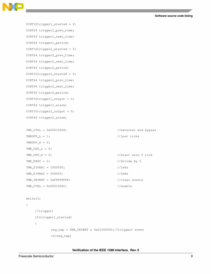
5 Required software setup for verificationAccording to the hardware setup, software must configure the 1588 module as follows:
1. Select the external clock as the clock source.2. Select bypass mode.3. Establish the proper divider factor (divided by 2) for the clock output.4. Set the counting-down counter (1000000) and enable PULSE_OUT1.5. Set the counting-down counter (500000) and enable PULSE_OUT2. 6. Enable the 1588 module.7. Start an endless loop, which initiates the following actions:
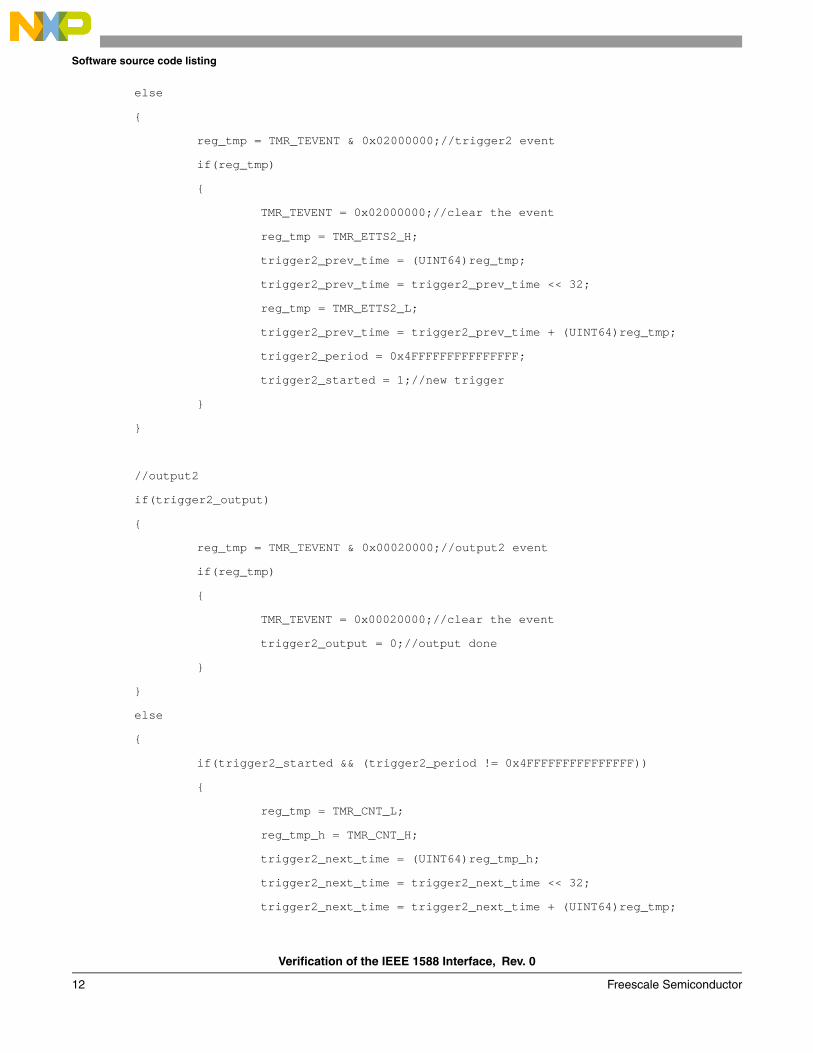
— Monitor and detect triggers on TRIG_IN1.— Calculate the period (average time between triggers) for TRIG_IN1.— Start an alarm on ALARM_OUT1 using the period of TRIG_IN1.— Monitor the alarm on ALARM_OUT1 and start a new alarm if it expires.— Monitor and detect triggers on TRIG_IN2.— Calculate the period (average time between triggers) for TRIG_IN2.— Start an alarm on ALARM_OUT2 using the period of TRIG_IN2.— Monitor the alarm on ALARM_OUT2 and start a new alarm if it expires.
6 Results of test verificationThe following figures illustrate the test results for the TSEC_1588_CLK_IN and TSEC_1588_CLK_OUT pins, the TSEC_1588_ALARM_OUT1 pin, and the TSEC_1588_ALARM_OUT2 pin.
Verification of the IEEE 1588 Interface, Rev. 0
Freescale Semiconductor 5
Results of test verification
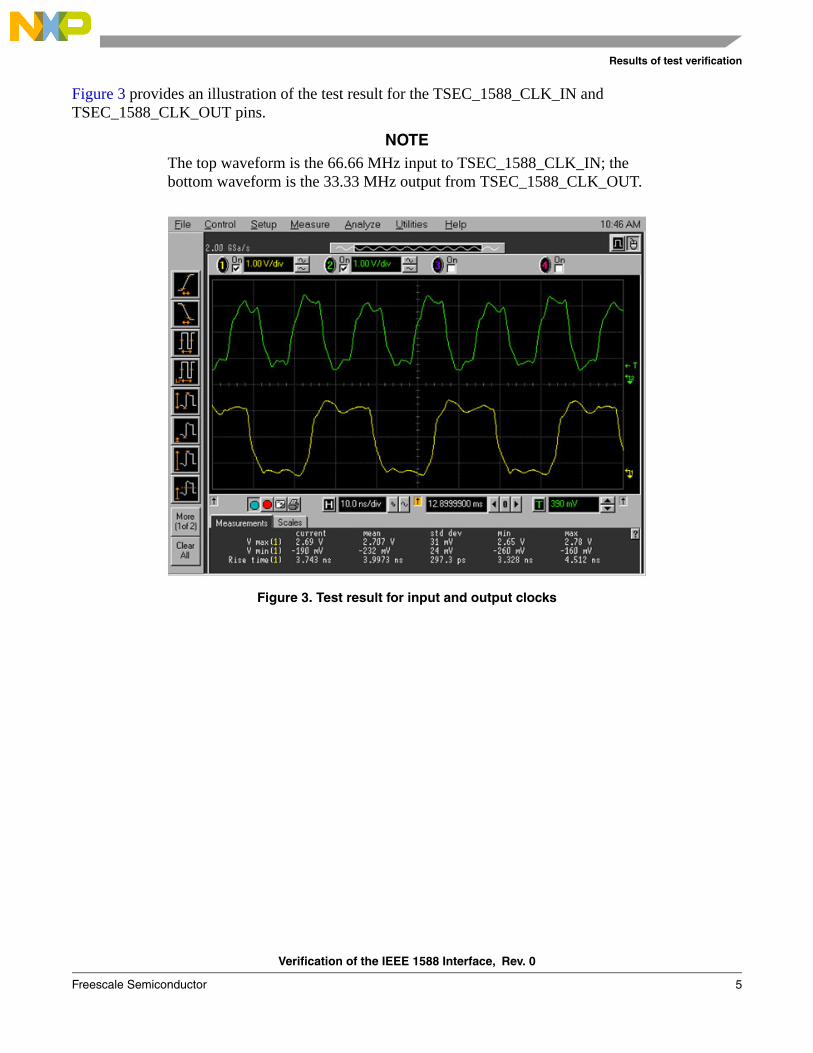
Figure 3 provides an illustration of the test result for the TSEC_1588_CLK_IN and TSEC_1588_CLK_OUT pins.
NOTEThe top waveform is the 66.66 MHz input to TSEC_1588_CLK_IN; the bottom waveform is the 33.33 MHz output from TSEC_1588_CLK_OUT.
Figure 3. Test result for input and output clocks
Verification of the IEEE 1588 Interface, Rev. 0
6 Freescale Semiconductor
Results of test verification
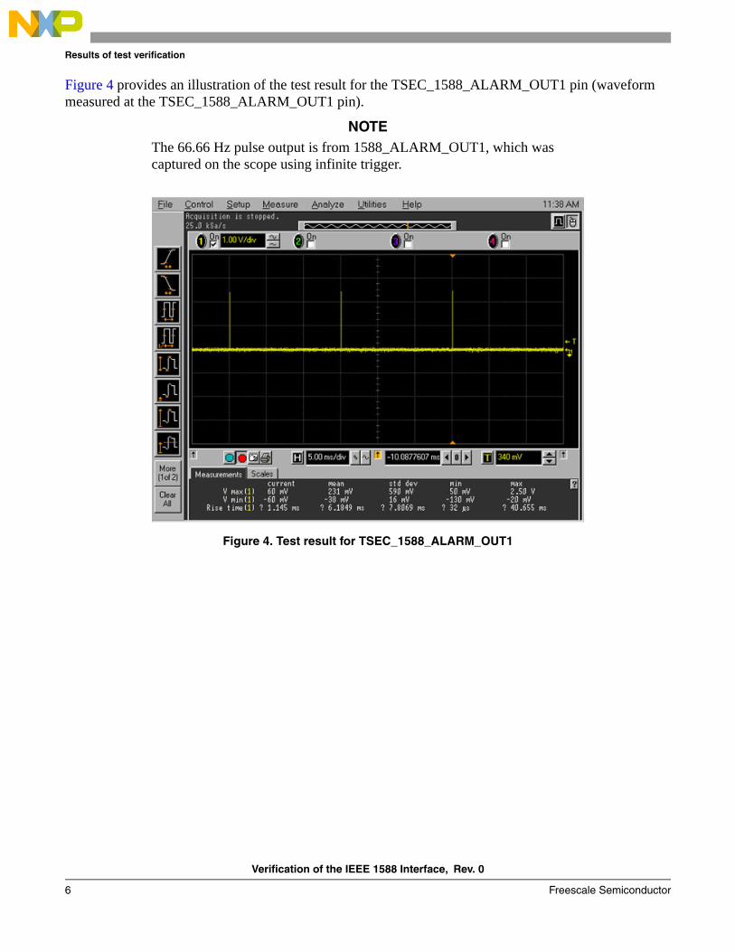
Figure 4 provides an illustration of the test result for the TSEC_1588_ALARM_OUT1 pin (waveform measured at the TSEC_1588_ALARM_OUT1 pin).
NOTEThe 66.66 Hz pulse output is from 1588_ALARM_OUT1, which was captured on the scope using infinite trigger.
Figure 4. Test result for TSEC_1588_ALARM_OUT1
Verification of the IEEE 1588 Interface, Rev. 0
Freescale Semiconductor 7
Software source code listing
Figure 5 provides an illustration of the test result for the TSEC_1588_ALARM_OUT2 pin (waveform measured at the TSEC_1588_ALARM_OUT2 pin).
NOTEThe 133.33 Hz pulse output is from 1588_ALARM_OUT2, which was captured on the scope using infinite trigger.
Figure 5. Test result for TSEC_1588_ALARM_OUT2
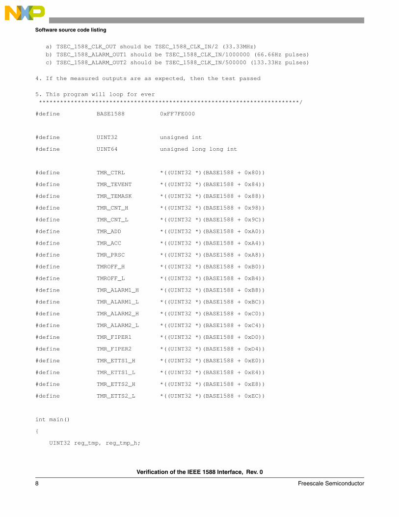
7 Software source code listingThe following is the source code listing. Although prepared for P1023RDB, this code also works with other Freescale products and boards with minor changes.
/******************************************************************************The following example code is intended to facilitate the testing of the 1588 interface:
1. BASE1588 shall be modified if the CCSRBAR is moved from the default
2. Before starting this testing program, a) A proper clock (25MHz to 200MHz) shall be applied to TSEC_1588_CLK_IN b) TSEC_1588_ALARM_OUT1 shall be tied to TSEC_1588_TRIG_IN1 c) TSEC_1588_ALARM_OUT2 shall be tied to TSEC_1588_TRIG_IN2 3. After this testing program is started, please measure the following signals using a scope (assume the TSEC_1588_CLK_IN is 66.66MHz for example)
Verification of the IEEE 1588 Interface, Rev. 0
8 Freescale Semiconductor
Software source code listing
a) TSEC_1588_CLK_OUT should be TSEC_1588_CLK_IN/2 (33.33MHz) b) TSEC_1588_ALARM_OUT1 should be TSEC_1588_CLK_IN/1000000 (66.66Hz pulses) c) TSEC_1588_ALARM_OUT2 should be TSEC_1588_CLK_IN/500000 (133.33Hz pulses)
4. If the measured outputs are as expected, then the test passed
5. This program will loop for ever **************************************************************************/
8 Revision history The following table provides a revision history for this application note.
Table 1. Document revision history
Rev.number
Date Substantive change(s)
0 07/2011 Initial public release
Document Number: AN4326Rev. 007/2011
Information in this document is provided solely to enable system and software
implementers to use Freescale Semiconductor products. There are no express or
implied copyright licenses granted hereunder to design or fabricate any integrated
circuits or integrated circuits based on the information in this document.
Freescale Semiconductor reserves the right to make changes without further notice to
any products herein. Freescale Semiconductor makes no warranty, representation or
guarantee regarding the suitability of its products for any particular purpose, nor does
Freescale Semiconductor assume any liability arising out of the application or use of
any product or circuit, and specifically disclaims any and all liability, including without
limitation consequential or incidental damages. “Typical” parameters which may be
provided in Freescale Semiconductor data sheets and/or specifications can and do
vary in different applications and actual performance may vary over time. All operating
parameters, including “Typicals” must be validated for each customer application by
customer’s technical experts. Freescale Semiconductor does not convey any license
under its patent rights nor the rights of others. Freescale Semiconductor products are
not designed, intended, or authorized for use as components in systems intended for
surgical implant into the body, or other applications intended to support or sustain life,
or for any other application in which the failure of the Freescale Semiconductor product
could create a situation where personal injury or death may occur. Should Buyer
purchase or use Freescale Semiconductor products for any such unintended or
unauthorized application, Buyer shall indemnify and hold Freescale Semiconductor
and its officers, employees, subsidiaries, affiliates, and distributors harmless against all
claims, costs, damages, and expenses, and reasonable attorney fees arising out of,
directly or indirectly, any claim of personal injury or death associated with such
unintended or unauthorized use, even if such claim alleges that Freescale
Semiconductor was negligent regarding the design or manufacture of the part.
How to Reach Us:
Home Page: www.freescale.com
Web Support: http://www.freescale.com/support
USA/Europe or Locations Not Listed: Freescale Semiconductor, Inc.Technical Information Center, EL5162100 East Elliot Road Tempe, Arizona 85284 1-800-521-6274 or+1-480-768-2130www.freescale.com/support