1 Verification of Welded eaves moment connection of open sections Ing. Lukáš Gödrich June 2014 1 Description The objective of this study: verification of CBFEM IDEARS software with component method. Description of verified connection: welded moment frame, horizontal beam is welded on the column flange, column stiffened with two horizontal stiffeners in levels of the beam flanges. Compressed parts are designed as maximal 3 rd class to avoid stability problems (horizontal stiffeners of column, web panel in shear or compression, compressed beam flange). Horizontal beam is considered as both sides fixed beam of length 6m loaded by continuous load over the entire length=>vertical shear force and bending moment in the plane are of the same absolute values. 2 Analytical model Component method Six components is examined: fillet weld, web panel in shear, column web in transverse compression, column web in transverse tension, column flange in bending and beam flange in compression. All components designed according to EN 1993-1-8. Design loads of component depend on the position: Web panel in shear– design loads on the vertical axis of the column Other components- reduced design loads in column flange to which is connected horizontal beam. 3.1 Fillet weld The weld is closed around a cross-section of the beam. The thickness of the weld on the flanges can differ from the thickness of the weld on the web. Vertical shear force is transferred only by welds on the web and plastic stress distribution is considered. Bending moment is transferred by whole weld shape and elastic stress distribution is considered. Effective weld width depending on the horizontal stiffness of the column is considered (because of bending of the column flange). Design of the weld is done according to EN1993-1-8 – 4.5.3.2(6). The assessment is carried out in two major points: on the upper or lower edge of the flange (maximum bending stress) and in the crossing of the flange and the web (combination of shear force and bending moment stresses).
Transcript
1
Verification of
Welded eaves moment connection of open sections Ing. Lukáš Gödrich
June 2014
1 Description The objective of this study: verification of CBFEM IDEARS software with component method.
Description of verified connection: welded moment frame, horizontal beam is welded on the column
flange, column stiffened with two horizontal stiffeners in levels of the beam flanges. Compressed
parts are designed as maximal 3rd class to avoid stability problems (horizontal stiffeners of column,
web panel in shear or compression, compressed beam flange). Horizontal beam is considered as both
sides fixed beam of length 6m loaded by continuous load over the entire length=>vertical shear force
and bending moment in the plane are of the same absolute values.
2 Analytical model
Component method
Six components is examined: fillet weld, web panel in shear, column web in transverse compression,
column web in transverse tension, column flange in bending and beam flange in compression.
All components designed according to EN 1993-1-8.
Design loads of component depend on the position:
Web panel in shear– design loads on the vertical axis of the column
Other components- reduced design loads in column flange to which is connected horizontal beam.
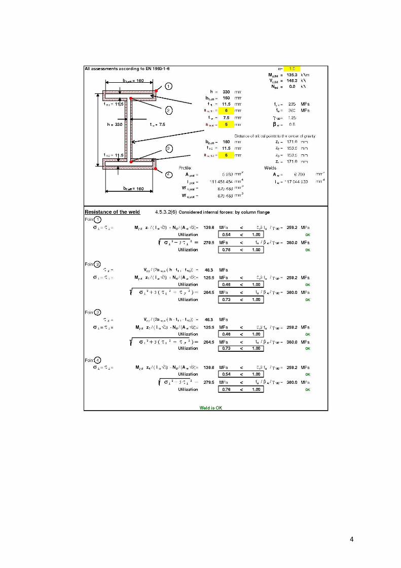
3.1 Fillet weld
The weld is closed around a cross-section of the beam.
The thickness of the weld on the flanges can differ from the thickness of the weld on the web.
Vertical shear force is transferred only by welds on the web and plastic stress distribution is
considered. Bending moment is transferred by whole weld shape and elastic stress distribution is
considered.
Effective weld width depending on the horizontal stiffness of the column is considered (because of
bending of the column flange).
Design of the weld is done according to EN1993-1-8 – 4.5.3.2(6).
The assessment is carried out in two major points: on the upper or lower edge of the flange
(maximum bending stress) and in the crossing of the flange and the web (combination of shear force
and bending moment stresses).
2
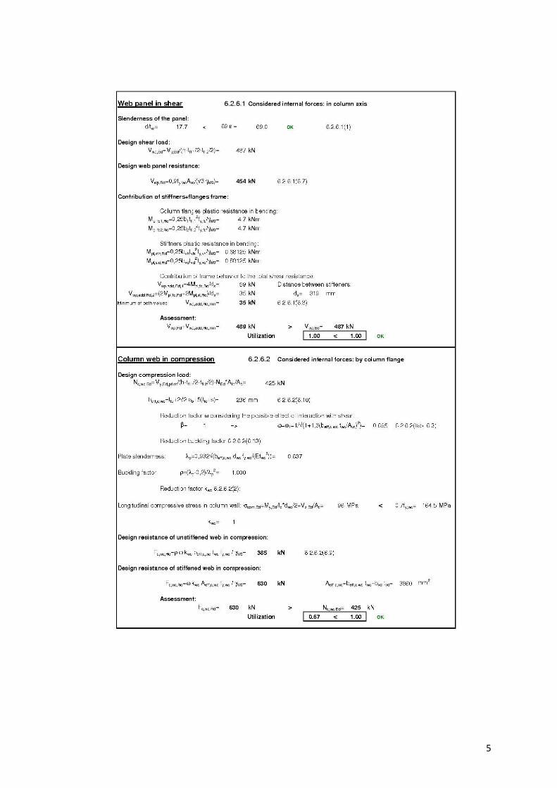
3.2 Web panel in shear
The thickness of the column web is designed to be maximally third class to avoid stability problem
see EN1993-1-8 – 6.2.6.1(1).
Two contributions to the load capacity are considered: resistance of the column wall in shear and the
contribution from the frame behaviour of the column flanges and horizontal stiffeners see EN1993-1-
8 – 6.2.6.1(6.7 and 6.8).
3.3 Column web in transverse compression
Effect of the interaction of the shear load is considered see EN1993-1-8 – 6.2.6.2(tab. 6.3).
Influence of longitudinal stress in the wall of the column is considered see EN1993-1-8 – 6.2.6.2(2).
Horizontal stiffeners prevent from stability problem
The horizontal stiffeners are included in the load capacity of this component with the effective area.
3.4 Column web in transverse tension
Effect of the interaction of the shear load is considered see EN1993-1-8 – 6.2.6.2(tab. 6.3).
The horizontal stiffeners are included in the load capacity of this component with the effective area.
3.5 Column flange in bending
Horizontal stiffeners brace column flange, this component is not considered.
3.6 Beam flange in compression
The horizontal beam is designed to be maximally third class to avoid stability problem.
3
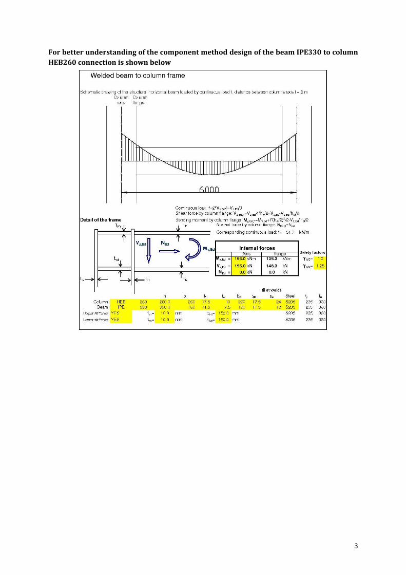
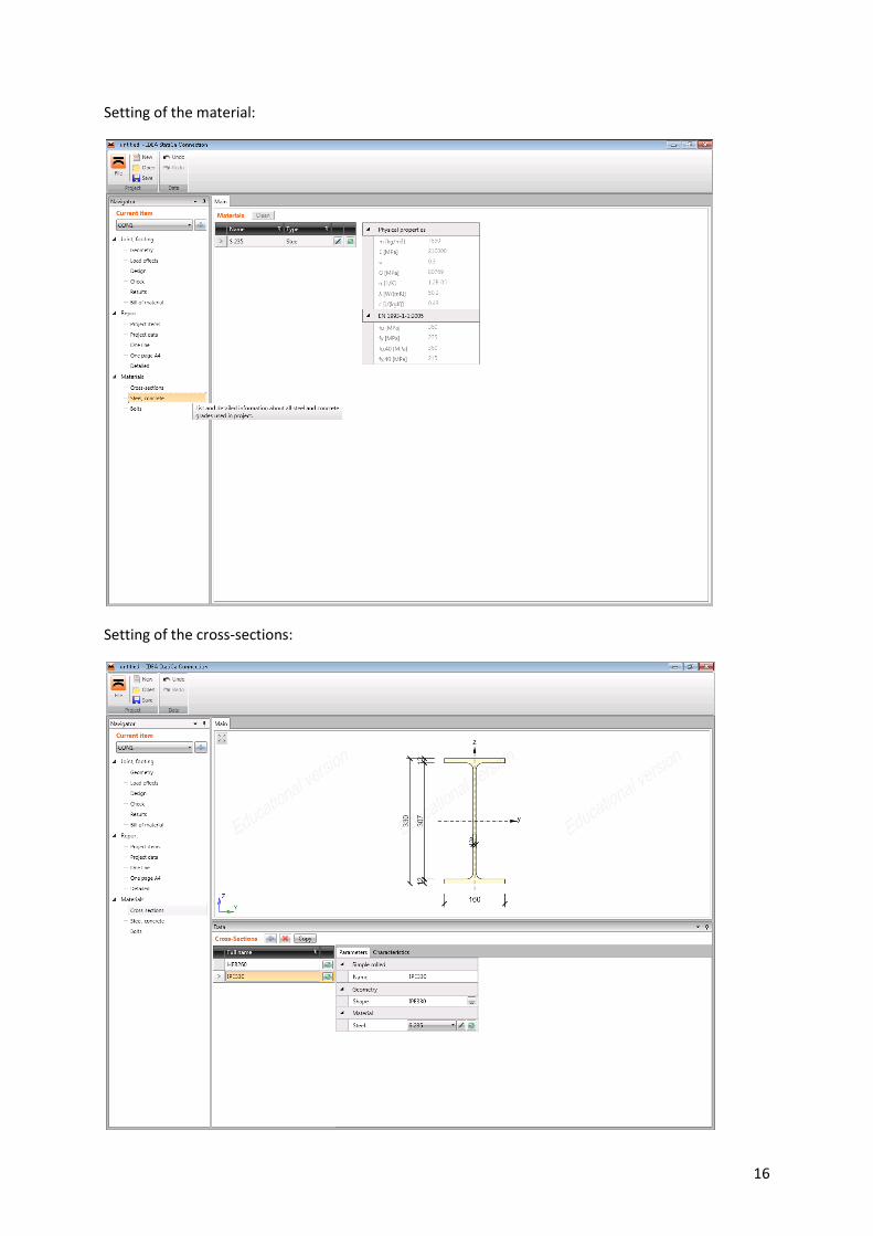
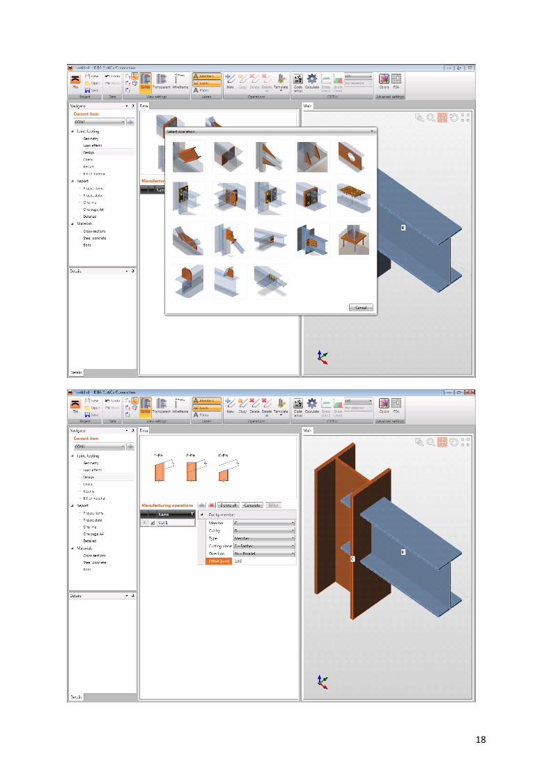
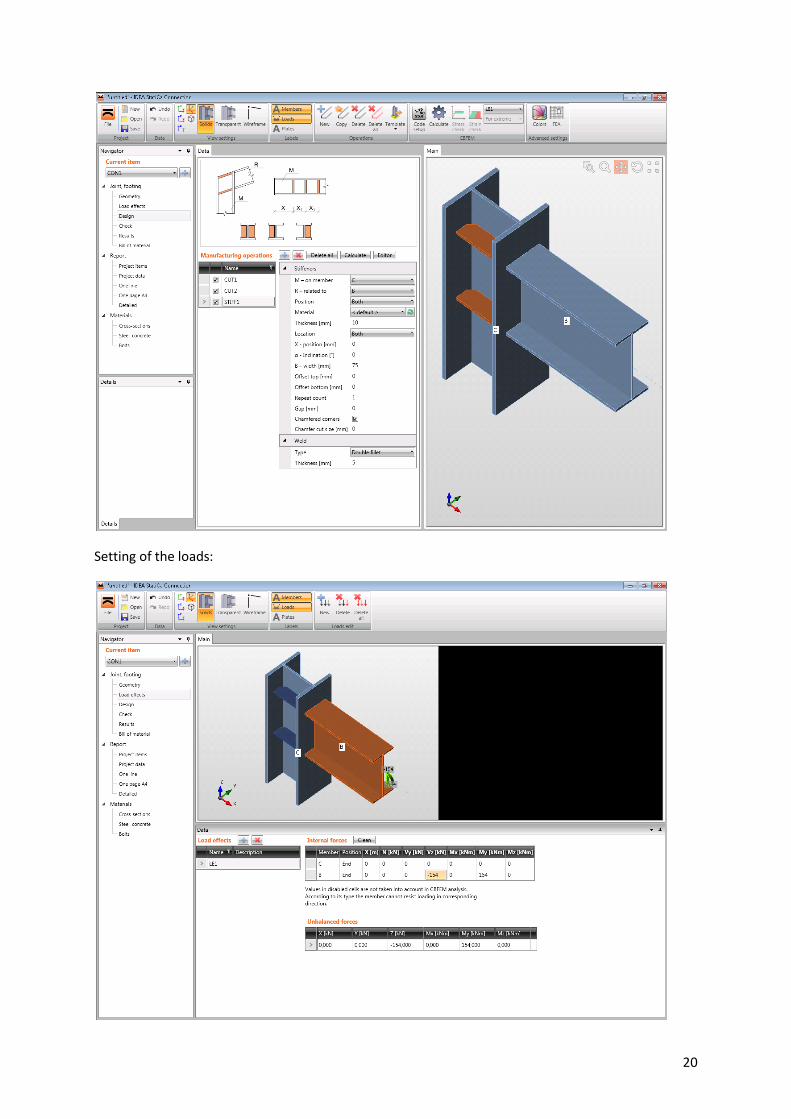
For better understanding of the component method design of the beam IPE330 to column
HEB260 connection is shown below
4
5
6
7
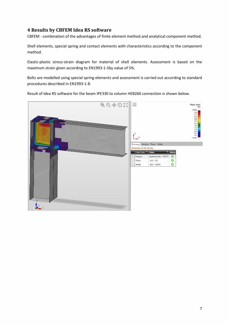
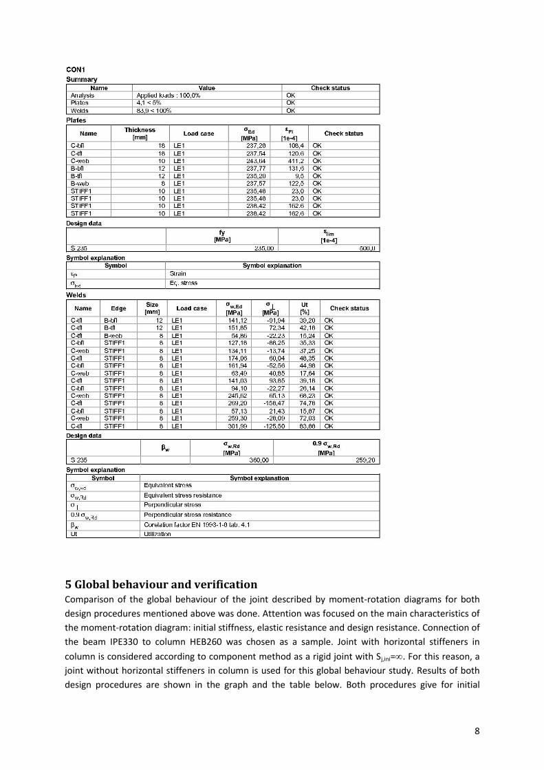
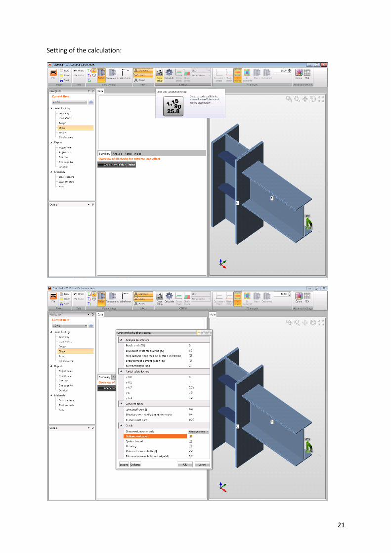
4 Results by CBFEM Idea RS software CBFEM - combination of the advantages of finite element method and analytical component method.
Shell elements, special spring and contact elements with characteristics according to the component
method.
Elastic-plastic stress-strain diagram for material of shell elements. Assessment is based on the
maximum strain given according to EN1993-1-5by value of 5%.
Bolts are modelled using special spring elements and assessment is carried out according to standard
procedures described in EN1993-1-8.
Result of Idea RS software for the beam IPE330 to column HEB260 connection is shown below.
8
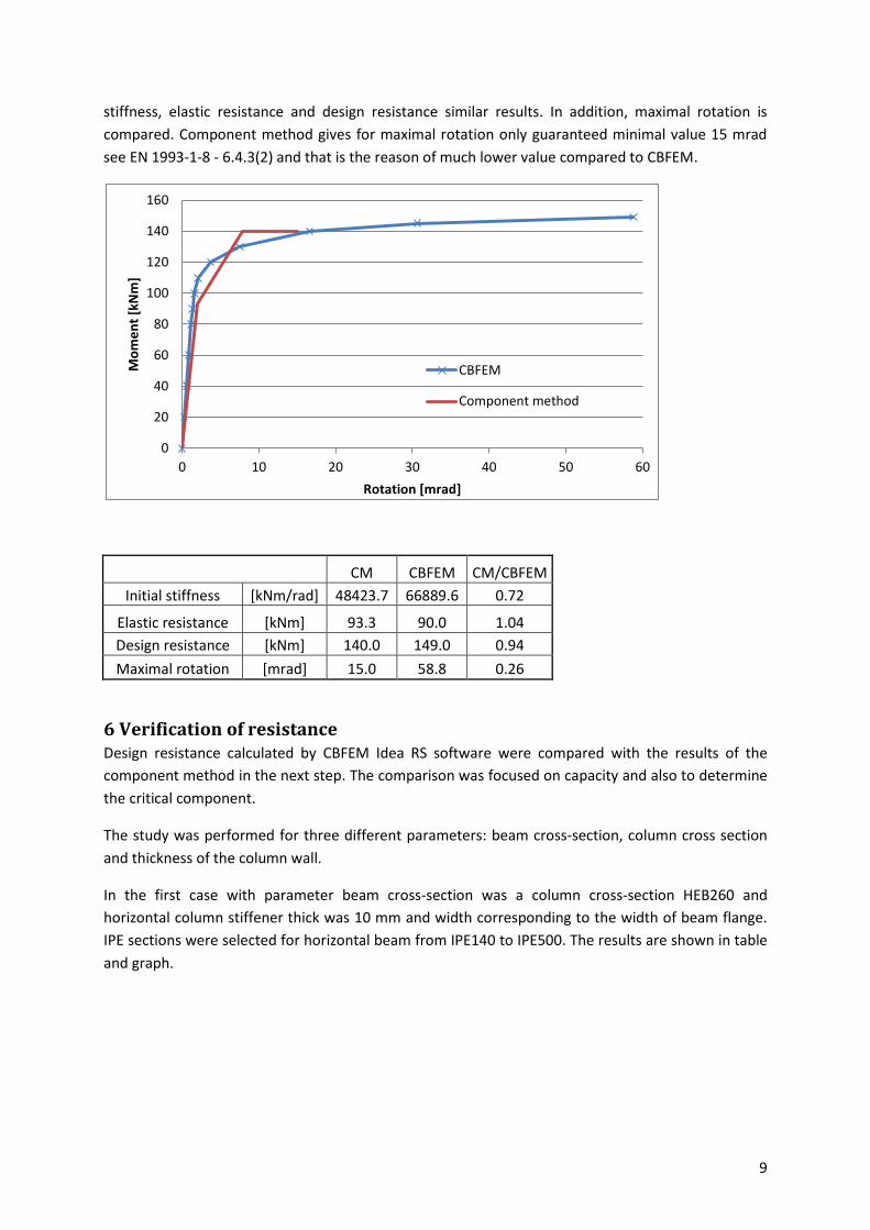
5 Global behaviour and verification Comparison of the global behaviour of the joint described by moment-rotation diagrams for both
design procedures mentioned above was done. Attention was focused on the main characteristics of
the moment-rotation diagram: initial stiffness, elastic resistance and design resistance. Connection of
the beam IPE330 to column HEB260 was chosen as a sample. Joint with horizontal stiffeners in
column is considered according to component method as a rigid joint with Sj,ini=. For this reason, a
joint without horizontal stiffeners in column is used for this global behaviour study. Results of both
design procedures are shown in the graph and the table below. Both procedures give for initial
9
stiffness, elastic resistance and design resistance similar results. In addition, maximal rotation is
compared. Component method gives for maximal rotation only guaranteed minimal value 15 mrad
see EN 1993-1-8 - 6.4.3(2) and that is the reason of much lower value compared to CBFEM.
CM CBFEM CM/CBFEM
Initial stiffness [kNm/rad] 48423.7 66889.6 0.72
Elastic resistance [kNm] 93.3 90.0 1.04
Design resistance [kNm] 140.0 149.0 0.94
Maximal rotation [mrad] 15.0 58.8 0.26
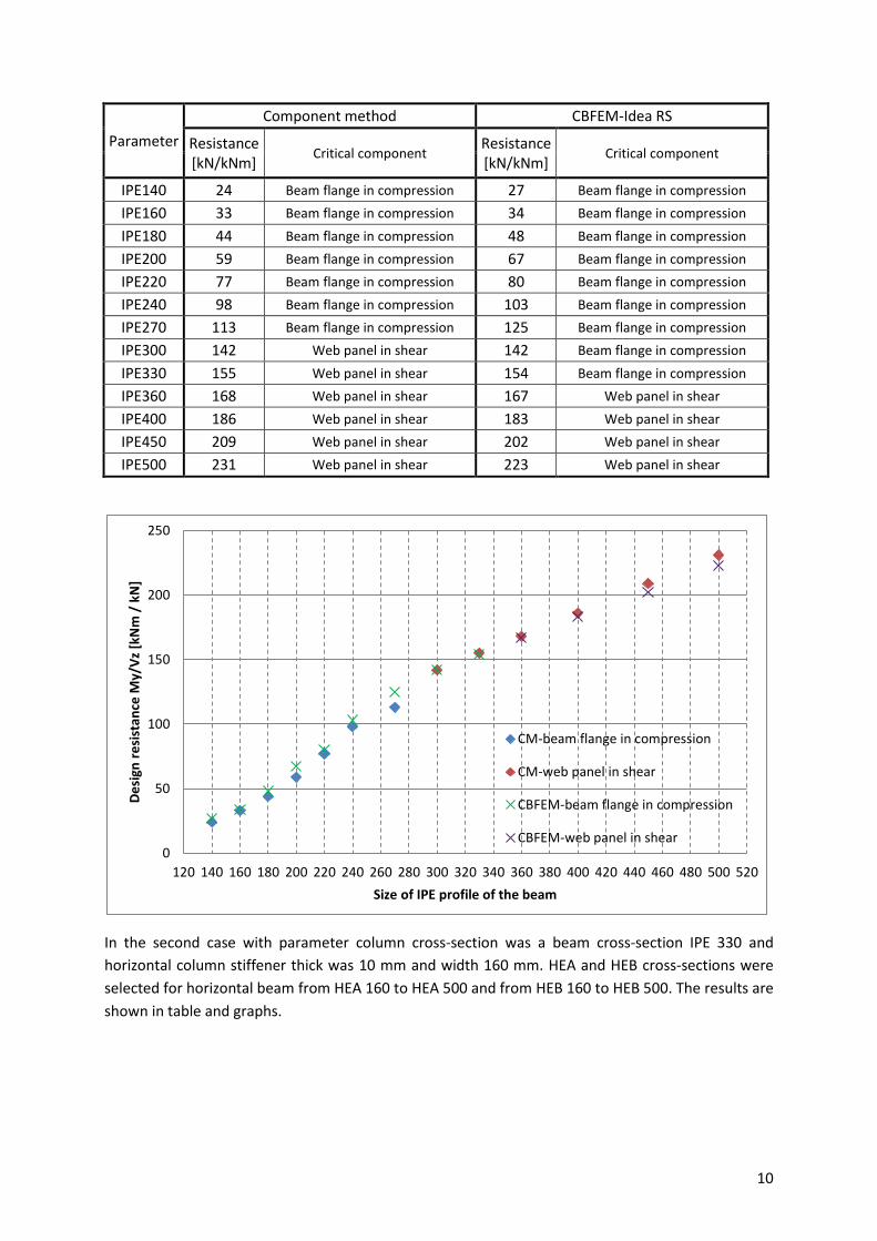
6 Verification of resistance Design resistance calculated by CBFEM Idea RS software were compared with the results of the
component method in the next step. The comparison was focused on capacity and also to determine
the critical component.
The study was performed for three different parameters: beam cross-section, column cross section
and thickness of the column wall.
In the first case with parameter beam cross-section was a column cross-section HEB260 and
horizontal column stiffener thick was 10 mm and width corresponding to the width of beam flange.
IPE sections were selected for horizontal beam from IPE140 to IPE500. The results are shown in table
and graph.
0
20
40
60
80
100
120
140
160
0 10 20 30 40 50 60
Mo
me
nt
[kN
m]
Rotation [mrad]
CBFEM
Component method
10
Parameter
Component method CBFEM-Idea RS
Resistance [kN/kNm]
Critical component Resistance [kN/kNm]
Critical component
IPE140 24 Beam flange in compression 27 Beam flange in compression
IPE160 33 Beam flange in compression 34 Beam flange in compression
IPE180 44 Beam flange in compression 48 Beam flange in compression
IPE200 59 Beam flange in compression 67 Beam flange in compression
IPE220 77 Beam flange in compression 80 Beam flange in compression
IPE240 98 Beam flange in compression 103 Beam flange in compression
IPE270 113 Beam flange in compression 125 Beam flange in compression
IPE300 142 Web panel in shear 142 Beam flange in compression
IPE330 155 Web panel in shear 154 Beam flange in compression
IPE360 168 Web panel in shear 167 Web panel in shear
IPE400 186 Web panel in shear 183 Web panel in shear
IPE450 209 Web panel in shear 202 Web panel in shear
IPE500 231 Web panel in shear 223 Web panel in shear
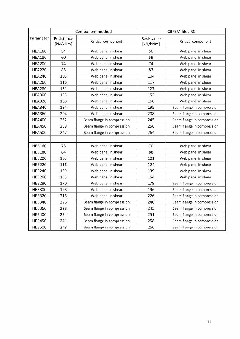
In the second case with parameter column cross-section was a beam cross-section IPE 330 and
horizontal column stiffener thick was 10 mm and width 160 mm. HEA and HEB cross-sections were
selected for horizontal beam from HEA 160 to HEA 500 and from HEB 160 to HEB 500. The results are