38
Verify 2003 System Debugging and Verification : A New Challenge Daniel Gajski Samar Abdi Center for Embedded Computer Systems http://www.cecs.uci.edu University of California, Irvine
| Date post: | 13-Dec-2015 |
| Category: |
Documents |
| Upload: | mitchell-jefferson |
| View: | 224 times |
| Download: | 3 times |
Verify 2003
System Debugging and Verification : A New Challenge
Daniel Gajski Samar Abdi
Center for Embedded Computer Systems
http://www.cecs.uci.edu
University of California, Irvine

Copyright 2003 Daniel Gajski, Samar AbdiVerify 2003
Overview
• Simulation and debugging methods
• Formal verification methods
• Comparative analysis of verification techniques
• Model formalization for SoC verification
• Conclusions

Copyright 2003 Daniel Gajski, Samar AbdiVerify 2003
Design Verification Methods
• Simulation based methods Specify input test vector, output test vector pair Run simulation and compare output against expected output
• Semi-formal Methods Specify inputs and outputs as symbolic expressions Check simulation output against expected expression
• Formal Methods Check equivalence of design models or parts of models Check specified properties on models

Copyright 2003 Daniel Gajski, Samar AbdiVerify 2003
Simulation
• Task : Create test vectors and simulate model• Inputs
Specification− Typically natural language, incomplete and informal− Used to create interesting stimuli and monitors
Model of DUT− Typically written in HDL or C or both
• Output Failed test vectors
− Pointed out in different design representations by debugging tools
Typical simulation environment
DUT
Sti
mul
us
Mon
itor
s
Specification

Copyright 2003 Daniel Gajski, Samar AbdiVerify 2003
Improvements to Simulation Environment
• Main drawback is coverage Several coverage metrics
− HDL statements, conditional branches, signal toggle, FSM states Each metric is incomplete by itself Exhaustive simulation for each coverage type is impractical
• Possible Improvements Stimulus optimizations
− Language to specify tests concisely vs. exhaustive enumeration− Write tests for uncovered parts of the model
Monitor optimizations− Assertions within design to point to simulation failures− Better debugging aids (correlation of code, waveforms and netlist)
Speedup techniques− Cycle simulation vs. event driven− Hardware prototyping on FPGA
Modeling techniques− Models at higher abstraction level simulate faster

Copyright 2003 Daniel Gajski, Samar AbdiVerify 2003
Stimulus optimizations
• Testbench Authoring Languages Generate test vectors instead of writing them down
− Pseudo random, constrained and directed tests
Several commercial and public domain “verification languages”− e, Vera, Jeda, TestBuilder
• Coverage Feedback Identify design parts that are not covered Create new tests to cover those parts
− controllability is a problem !
x y z x y z
11
10
coverage analysis
Copyright 2003 Daniel Gajski, Samar AbdiVerify 2003
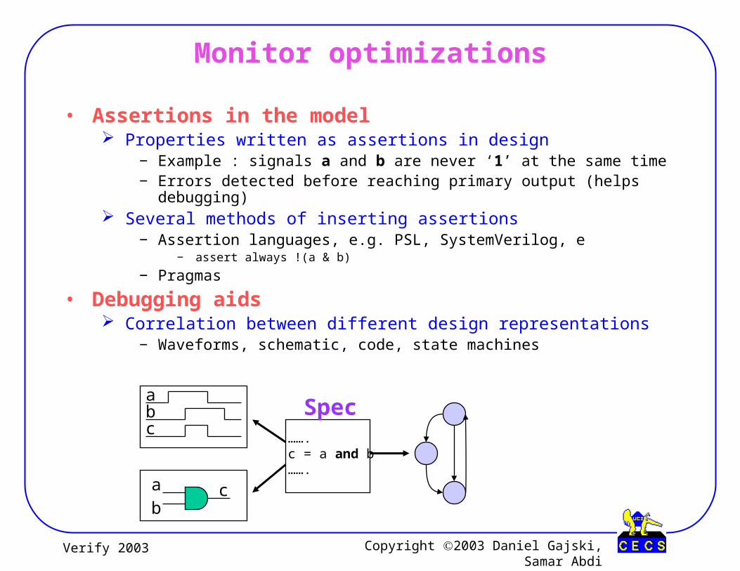
• Assertions in the model Properties written as assertions in design
− Example : signals a and b are never ‘1’ at the same time− Errors detected before reaching primary output (helps debugging)
Several methods of inserting assertions− Assertion languages, e.g. PSL, SystemVerilog, e
− assert always !(a & b)
− Pragmas
• Debugging aids Correlation between different design representations
− Waveforms, schematic, code, state machines
Monitor optimizations
…….c = a and b…….
a
bc
abc
Spec

Copyright 2003 Daniel Gajski, Samar AbdiVerify 2003
Speedup techniques
• Cycle simulation Observe signals once per clock cycle Cannot observe glitches within a clock cycle
• Emulation Prototype hardware model on FPGAs Much faster than software simulation In-circuit emulation
− FPGA is inserted on board instead of real component Simulation acceleration
− Emulate parts of hardware by interfacing with software simulator
Spec
Non-synthesizable
synthesizable
SW
FPGA ISS / HDL simulator
Copyright 2003 Daniel Gajski, Samar AbdiVerify 2003
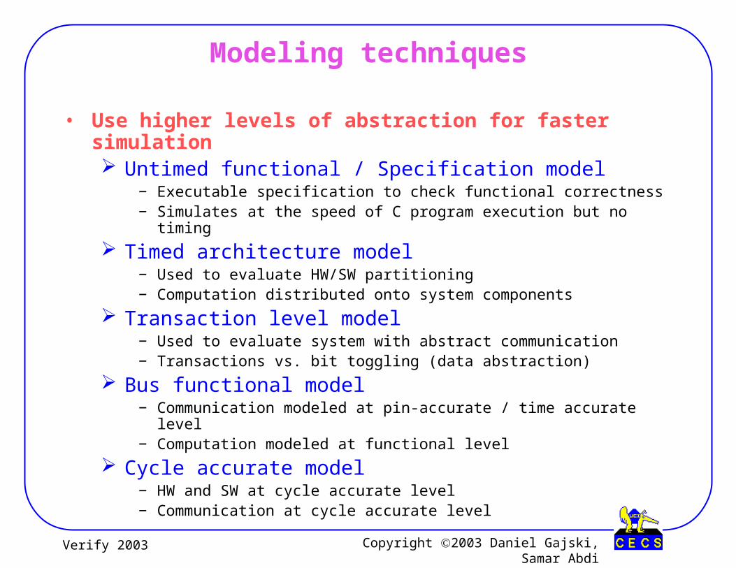
Modeling techniques
• Use higher levels of abstraction for faster simulation Untimed functional / Specification model
− Executable specification to check functional correctness− Simulates at the speed of C program execution but no timing
Timed architecture model− Used to evaluate HW/SW partitioning− Computation distributed onto system components
Transaction level model− Used to evaluate system with abstract communication− Transactions vs. bit toggling (data abstraction)
Bus functional model− Communication modeled at pin-accurate / time accurate level− Computation modeled at functional level
Cycle accurate model− HW and SW at cycle accurate level− Communication at cycle accurate level
Copyright 2003 Daniel Gajski, Samar AbdiVerify 2003
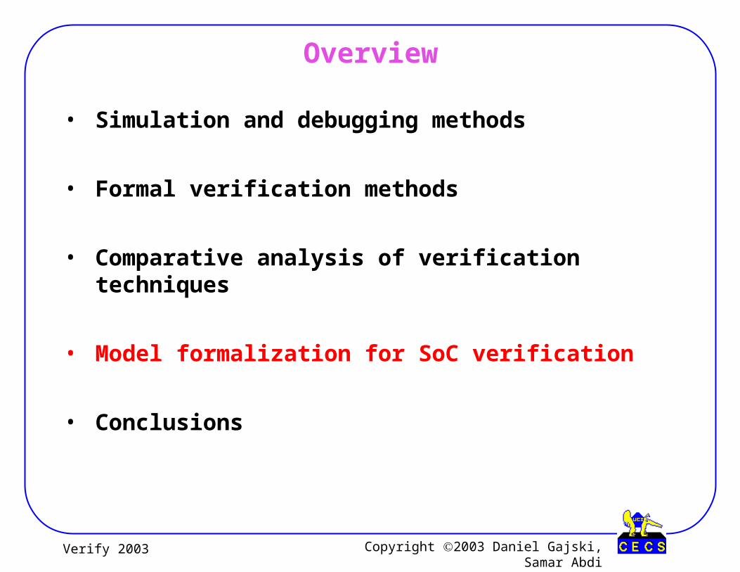
Overview
• Simulation and debugging methods
• Formal verification methods
• Comparative analysis of verification techniques
• Model formalization for SoC verification
• Conclusions

Copyright 2003 Daniel Gajski, Samar AbdiVerify 2003
Formal Verification Methods
• Equivalence Checking Compare optimized/synthesized model against original model
• Model Checking Check if a model satisfies a given property
• Theorem Proving Prove implementation is equivalent to specification in some formalism

Copyright 2003 Daniel Gajski, Samar AbdiVerify 2003
Logic Equivalence Checking
• Task : Check functional equivalence of two designs• Inputs
Reference (golden) design Optimized (synthesized) design Logic segments between registers, ports or black boxes
• Output Matched logic segment equivalent/not equivalent
• Use canonical form in boolean logic to match segments
1 = 1’ ?2= 2’ ?
inpu
ts
outp
uts
12
inpu
ts
outp
uts
1’2’
Equivalence result
Reference design
Optimized design

Copyright 2003 Daniel Gajski, Samar AbdiVerify 2003
FSM Equivalence Checking (1/2)
• Finite State Machine M : < I, O, Q, Q0, F, H >
− I is the set of inputs− O is the set of outputs− Q is the set of states− Q0 is the set of initial states− F is the state transition function Q × I Q− H is the output function Q O
• FSM as a language acceptor Define Qf to be the set of final states M accepts string S of symbols in I if
− applying symbols of S to a state in Q0 leads to a state in Qf Set of strings accepted by M is its language
• Product FSM Define product FSM as a parallel composition of two machines
− M1: < I, O1, Q1, Q01, F1, H1 > , M2: < I, O2, Q2, Q02, F2, H2 > − M1×M2 : <I, O1×O2, Q1×Q2, Q01×Q02, F1× F2, H1×H2 >
Copyright 2003 Daniel Gajski, Samar AbdiVerify 2003
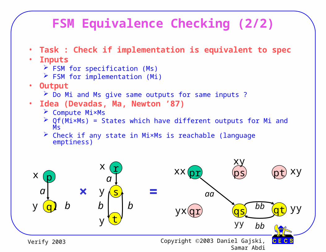
FSM Equivalence Checking (2/2)
• Task : Check if implementation is equivalent to spec• Inputs
FSM for specification (Ms) FSM for implementation (Mi)
• Output Do Mi and Ms give same outputs for same inputs ?
• Idea (Devadas, Ma, Newton ’87) Compute Mi×Ms Qf(Mi×Ms) = States which have different outputs for Mi and Ms Check if any state in Mi×Ms is reachable (language emptiness)
p
q
x
y
a
b
r
s
x
ya
bty
b
pr
qr
ps pt
qs qt
xx
yx
xyxy
yy
yy
aa
bb
bb
× =
Copyright 2003 Daniel Gajski, Samar AbdiVerify 2003
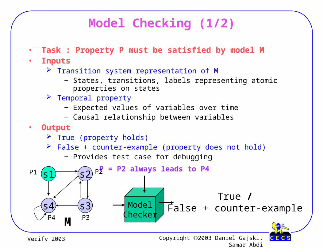
Model Checking (1/2)
• Task : Property P must be satisfied by model M• Inputs
Transition system representation of M− States, transitions, labels representing atomic properties on states
Temporal property− Expected values of variables over time− Causal relationship between variables
• Output True (property holds) False + counter-example (property does not hold)
− Provides test case for debugging
True /False + counter-exampleModel
Checker
P = P2 always leads to P4s1
s4 s3
s2P1
P3P4
P2
M

Copyright 2003 Daniel Gajski, Samar AbdiVerify 2003
Model Checking (2/2)
• Idea (Clarke, Emerson ’81) Unroll transition system to
an infinite computation tree− Start state is the root (S1)
Define properties using − On all paths (A)
− On some path (E)
− Always / Globally (G)
− Eventually (F)
Some examples− EG p
− AG p
− EF p
− AF p
• State space explosion What next ?
s1
s4 s3
s2
Transition system
s1
s2 s4
s3 s4 s4
s4s4s2 s4
Computation Tree
Copyright 2003 Daniel Gajski, Samar AbdiVerify 2003
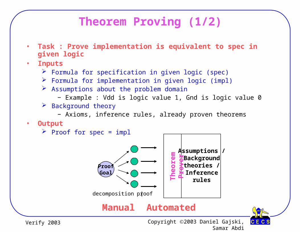
Theorem Proving (1/2)
• Task : Prove implementation is equivalent to spec in given logic• Inputs
Formula for specification in given logic (spec) Formula for implementation in given logic (impl) Assumptions about the problem domain
− Example : Vdd is logic value 1, Gnd is logic value 0 Background theory
− Axioms, inference rules, already proven theorems
• Output Proof for spec = impl
AutomatedManual
ProofGoal
Assumptions /Background
theories /Inference
rules
decomposition | proof
Th
eore
m P
rove
r

Copyright 2003 Daniel Gajski, Samar AbdiVerify 2003
Theorem Proving (2/2)
• Example CMOS inverter (Gordon’92) Using higher order logic
• Assumptions Vdd(y) := (y=T) Gnd(y) := (y=F) Ntran(x,y1,y2) := (x->(y1=y2)) Ptran(x,y1,y2) := (┐x->(y1=y2))
• Impl(x,y) := w1, w2. Vdd(w1) Λ Ptran(x,w1,y) Λ Ntran(x,y,w2) Λ Gnd(w2)
• Spec(x,y) := (y=┐x)• Proof
Impl(x,y) = ….. (assumption / thm / axiom) = ….. (assumption / thm / axiom)
= ….. (assumption / thm / axiom)
= Spec(x,y)
ш
Vdd
Gnd
x y
w1
w2
CMOS inverter
Copyright 2003 Daniel Gajski, Samar AbdiVerify 2003
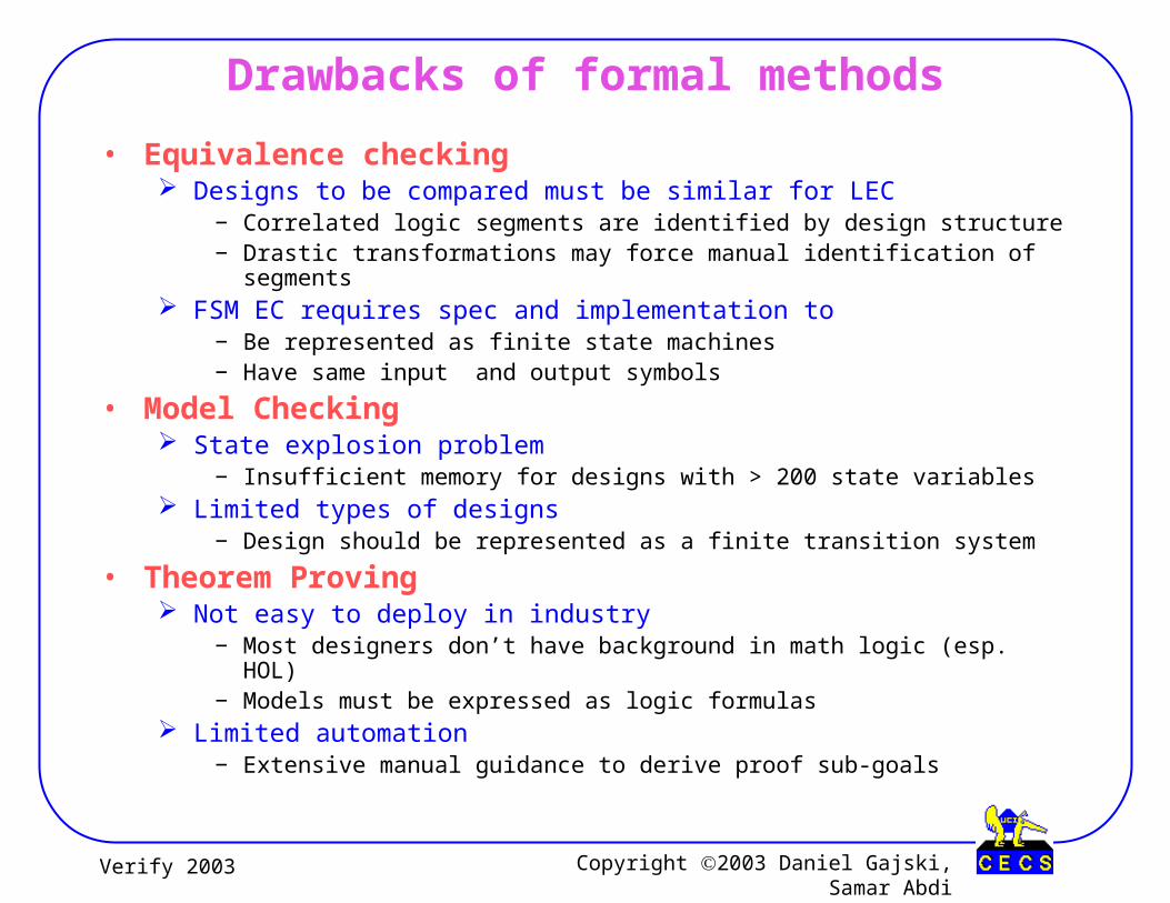
Drawbacks of formal methods
• Equivalence checking Designs to be compared must be similar for LEC
− Correlated logic segments are identified by design structure− Drastic transformations may force manual identification of segments
FSM EC requires spec and implementation to− Be represented as finite state machines− Have same input and output symbols
• Model Checking State explosion problem
− Insufficient memory for designs with > 200 state variables Limited types of designs
− Design should be represented as a finite transition system
• Theorem Proving Not easy to deploy in industry
− Most designers don’t have background in math logic (esp. HOL)− Models must be expressed as logic formulas
Limited automation− Extensive manual guidance to derive proof sub-goals
Copyright 2003 Daniel Gajski, Samar AbdiVerify 2003
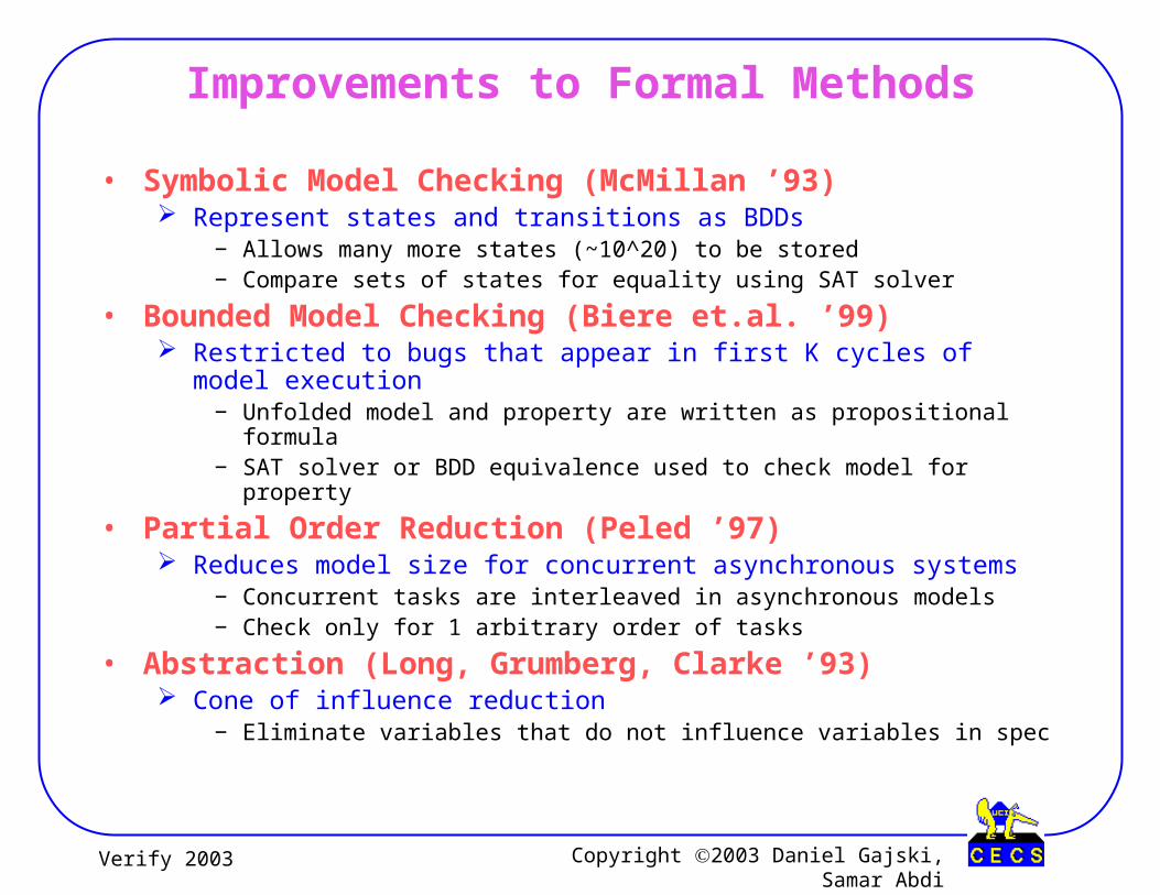
Improvements to Formal Methods
• Symbolic Model Checking (McMillan ’93) Represent states and transitions as BDDs
− Allows many more states (~10^20) to be stored− Compare sets of states for equality using SAT solver
• Bounded Model Checking (Biere et.al. ’99) Restricted to bugs that appear in first K cycles of model execution
− Unfolded model and property are written as propositional formula− SAT solver or BDD equivalence used to check model for property
• Partial Order Reduction (Peled ’97) Reduces model size for concurrent asynchronous systems
− Concurrent tasks are interleaved in asynchronous models− Check only for 1 arbitrary order of tasks
• Abstraction (Long, Grumberg, Clarke ’93) Cone of influence reduction
− Eliminate variables that do not influence variables in spec

Copyright 2003 Daniel Gajski, Samar AbdiVerify 2003
Semi-formal Methods (Symbolic Simulation)
• Task : Check if implementation satisfies specification• Inputs
Simulation model of the circuit Specification of expected behavior (as boolean expressions)
• Output Expression for the signals in design
• Idea (Bryant ’90) Encode set of inputs symbolically (using BDD) Evaluate output expressions during simulation Compare simulation output with expected output
− using BDD canonical form
Simulation model
abcd
f(a,b,c,d)?= g(a,b,c,d) Specification

Copyright 2003 Daniel Gajski, Samar AbdiVerify 2003
Overview
• Simulation and debugging methods
• Formal verification methods
• Comparative analysis of verification techniques
• Model formalization for SoC verification
• Conclusions

Copyright 2003 Daniel Gajski, Samar AbdiVerify 2003
Evaluation Metrics
• Coverage How exhaustive is the technique ?
− % of statements covered
− % of branches taken
− % of states visited / state transitions taken
• Cost and Effort How expensive is the technique ?
− Dollars spent per simulation / emulation cycle
− Training time for users
• Scalability How well does the technique scale with design size / abstraction ?
− Tool capacity
− Tool applicability for various modeling abstraction levels

Copyright 2003 Daniel Gajski, Samar AbdiVerify 2003
Coverage
Equivalence checking
Theorem provingModel checking
Symbolic simulation
Simulation with Assertions
Pseudo-random simulation
• Formal methods provide complete coverage For a specified property For a reference model
• Simulation with assertions Improves understanding of
design− White box vs. black box testing
High
Medium
Low

Copyright 2003 Daniel Gajski, Samar AbdiVerify 2003
Cost and Effort
• Pseudo-random simulation Writing monitors
• Simulation with assertions Identifying properties Writing assertions
• Equivalence checking Correlating logic segments
• Model checking Writing assertions
• Theorem proving Training (~ 6 months) Identifying assumptions Creating sub-goals
Equivalence checking
Theorem proving
Model checking
Symbolic simulation
Simulation with Assertions
Pseudo-random simulation
Low
Medium
High
Copyright 2003 Daniel Gajski, Samar AbdiVerify 2003
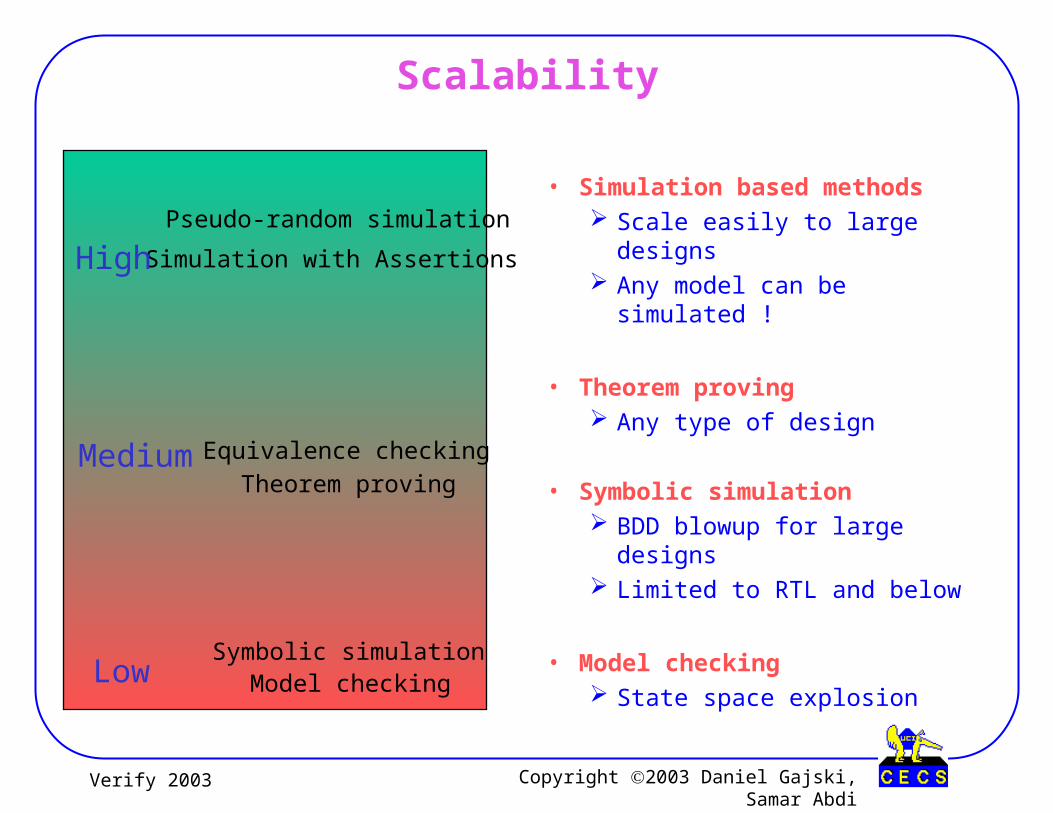
Scalability
• Simulation based methods Scale easily to large designs Any model can be simulated !
• Theorem proving Any type of design
• Symbolic simulation BDD blowup for large designs Limited to RTL and below
• Model checking State space explosion
Equivalence checking
Theorem proving
Model checkingSymbolic simulation
Simulation with Assertions
Pseudo-random simulation
High
Medium
Low
Copyright 2003 Daniel Gajski, Samar AbdiVerify 2003
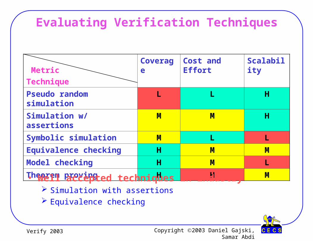
Evaluating Verification Techniques
Metric
Technique
Coverage Cost and Effort Scalability
Pseudo random simulation L L H
Simulation w/ assertions M M H
Symbolic simulation M L L
Equivalence checking H M M
Model checking H M L
Theorem proving H H M
• Well accepted techniques in industry Simulation with assertions Equivalence checking
Copyright 2003 Daniel Gajski, Samar AbdiVerify 2003
Overview
• Simulation and debugging methods
• Formal verification methods
• Comparative analysis of verification techniques
• Model formalization for SoC verification
• Conclusions

Copyright 2003 Daniel Gajski, Samar AbdiVerify 2003
New Verification Challenges for SoC Design
• Design complexity Size
− Verification either takes unreasonable time (eg. Logic simulation)
− Or takes unreasonable memory (eg. Model Checking)
Heterogeneity− HW / SW components on the same chip
− Interface problems
− Interdependence of both design teams
• Possible directions Methodology
− Unified HW/SW models
− Model formalization
− Automatic model transformations

Copyright 2003 Daniel Gajski, Samar AbdiVerify 2003
System Level Methodology
• Well defined specification Complete Just another model
• Well defined system models Several possible models Well defined semantics Formal representation
• Model verification Design decisions => transformations Formally defined transformations Automatic model generation possible Equivalence by construction
System Specification model
Intermediate models
Cycle accurate implementation model
Copyright 2003 Daniel Gajski, Samar AbdiVerify 2003
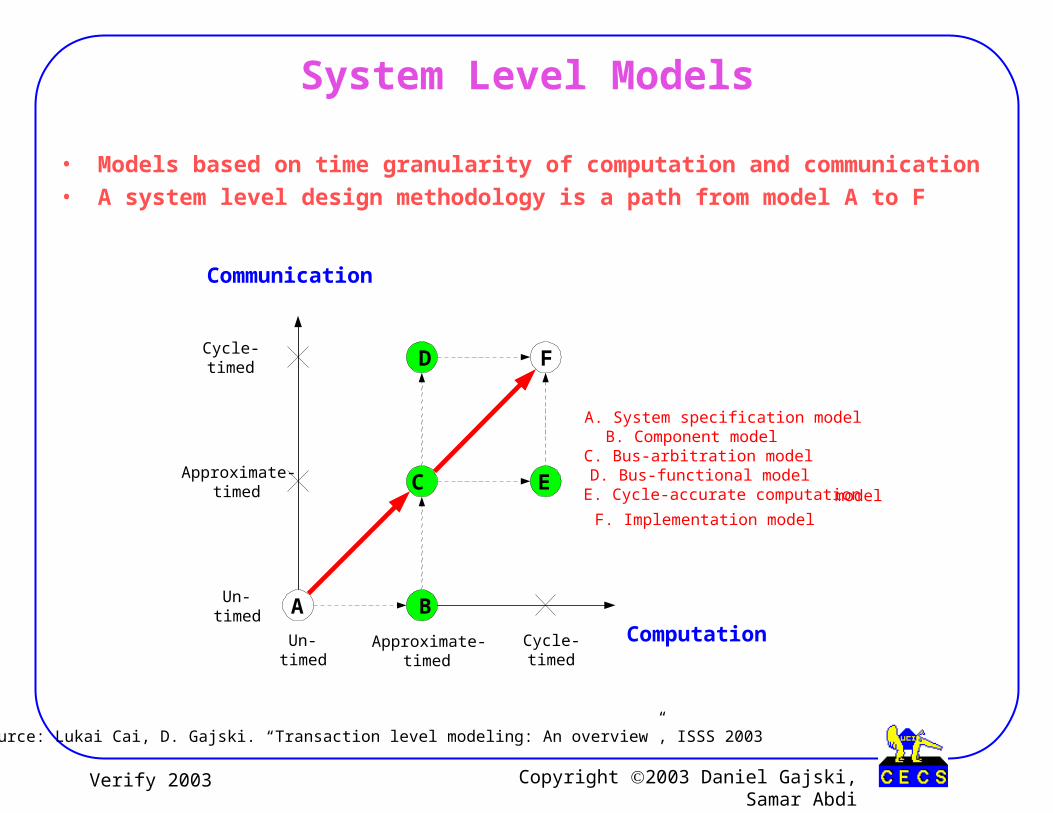
System Level Models
• Models based on time granularity of computation and communication• A system level design methodology is a path from model A to F
Computation
Communication
A B
C
D F
Un-timed
Approximate-timed
Cycle-timed
Un-timed
Approximate-timed
A. System specification modelB. Component modelC. Bus-arbitration modelD. Bus-functional modelE. Cycle-accurate computation model
F. Implementation model
E
Cycle-timed
Source: Lukai Cai, D. Gajski. “Transaction level modeling: An overview”, ISSS 2003
Copyright 2003 Daniel Gajski, Samar AbdiVerify 2003
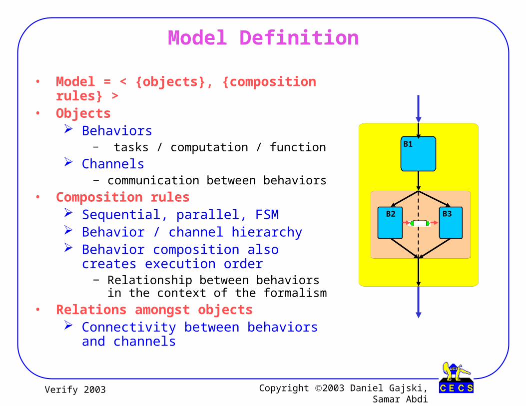
Model Definition
• Model = < {objects}, {composition rules} >• Objects
Behaviors − tasks / computation / function
Channels− communication between behaviors
• Composition rules Sequential, parallel, FSM Behavior / channel hierarchy Behavior composition also creates
execution order− Relationship between behaviors in the
context of the formalism
• Relations amongst objects Connectivity between behaviors and
channels
B2 B3
B1

Copyright 2003 Daniel Gajski, Samar AbdiVerify 2003
Model Transformations (1/2)
• Design Decision Map behaviors to PEs
• Model Transformations Rearrange object composition
− Distribute computation over PEs
Replace objects− Import IP components
Add / Remove synchronization− Transform sequential composition to
parallel and vice-versa
a*(b+c) = a*b + a*c
Distributivity of multiplication over addition
analogous to……
B1
B2 B3=
Distribution of behaviors (tasks)over components
PE IP
B2 B3
B1

Copyright 2003 Daniel Gajski, Samar AbdiVerify 2003
Model Transformations (2/2)
• Design Decision Map channels to buses
• Model Transformations Rearrange object composition
− Group channels according to bus mapping
− Slice complex data into bus words
Replace objects− Import bus protocol channels
a+b+c+d = (a+b) + (c+d)
Associativity of addition
analogous to……
=
Mapping of channels to buses
P E I P P E I P
Copyright 2003 Daniel Gajski, Samar AbdiVerify 2003
Model Refinement
• Definition Ordered set of transformations < tm, … , t2, t1 > is a refinement
− model B = tm( … ( t2( t1( model A ) ) ) … )
• Equivalence verification Each transformation maintains functional equivalence The refinement is thus correct by construction
• Derives a more detailed model from an abstract one Specific sequence for each model refinement Not all sequences are relevant
• Refinement based system level methodology Methodology := < {models}, {refinements} >

Copyright 2003 Daniel Gajski, Samar AbdiVerify 2003
System Verification through Refinement
• Set of models• Designer Decisions => transformations
Select components / connections− Import behaviors / protocols
Map behaviors / channels− Synchronize behaviors / slice data
• Transformations preserve equivalence Same partial order of tasks Same input/output data for each task Same partial order of data transactions Equivalent replacements
• All refined models will be “equivalent” to input model
Still need to verifyFirst model
Correctness of replacements
RefinementTool
t1t2…tm
Model A
Model B
DesignerDecisions
Library ofobjects
Copyright 2003 Daniel Gajski, Samar AbdiVerify 2003
Conclusion
• Variety of verification techniques available Several tools from industry and academia Each technique works well for specific kind / level of models
• Challenges for verification of large system designs Simulation based techniques take way too long
− Time to market issues Most formal techniques cannot scale
− Memory requirement explosion− Too much manual effort required
• Modeling is pushed to system level• Future design and verification
Complete and executable functional specification model Well defined semantics for models at different abstraction levels Well defined transformations for design decisions
− Verify transformations− Automate refinements
• Formalism helps system verification !

Verify 2003
Thank You !
![[ABDI H.] Principal Component Analysis](https://static.documents.pub/doc/80x56/55cf8593550346484b8f8649/abdi-h-principal-component-analysis.jpg)


