559
Veritas™ Cluster Server Installation Guide Solaris 6.0.1 July 2012
Veritas™ Cluster ServerInstallation Guide
Solaris
6.0.1
July 2012
Veritas Cluster Server Installation GuideThe software described in this book is furnished under a license agreement and may be usedonly in accordance with the terms of the agreement.
Product version: 6.0.1
Document version: 6.0.1 Rev 0
Legal NoticeCopyright © 2012 Symantec Corporation. All rights reserved.
Symantec, the Symantec logo, Veritas, Veritas Storage Foundation, CommandCentral,NetBackup, Enterprise Vault, and LiveUpdate are trademarks or registered trademarks ofSymantec corporation or its affiliates in the U.S. and other countries. Other names may betrademarks of their respective owners.
The product described in this document is distributed under licenses restricting its use,copying, distribution, and decompilation/reverse engineering. No part of this documentmay be reproduced in any form by any means without prior written authorization ofSymantec Corporation and its licensors, if any.
THE DOCUMENTATION IS PROVIDED "AS IS" AND ALL EXPRESS OR IMPLIED CONDITIONS,REPRESENTATIONS AND WARRANTIES, INCLUDING ANY IMPLIED WARRANTY OFMERCHANTABILITY, FITNESS FOR A PARTICULAR PURPOSE OR NON-INFRINGEMENT,ARE DISCLAIMED, EXCEPT TO THE EXTENT THAT SUCH DISCLAIMERS ARE HELD TOBE LEGALLY INVALID. SYMANTEC CORPORATION SHALL NOT BE LIABLE FOR INCIDENTALOR CONSEQUENTIAL DAMAGES IN CONNECTION WITH THE FURNISHING,PERFORMANCE, OR USE OF THIS DOCUMENTATION. THE INFORMATION CONTAINEDIN THIS DOCUMENTATION IS SUBJECT TO CHANGE WITHOUT NOTICE.
The Licensed Software and Documentation are deemed to be commercial computer softwareas defined in FAR 12.212 and subject to restricted rights as defined in FAR Section 52.227-19"Commercial Computer Software - Restricted Rights" and DFARS 227.7202, "Rights inCommercial Computer Software or Commercial Computer Software Documentation", asapplicable, and any successor regulations. Any use, modification, reproduction release,performance, display or disclosure of the Licensed Software and Documentation by the U.S.Government shall be solely in accordance with the terms of this Agreement.

Symantec Corporation350 Ellis StreetMountain View, CA 94043
http://www.symantec.com
Technical SupportSymantec Technical Support maintains support centers globally. TechnicalSupport’s primary role is to respond to specific queries about product featuresand functionality. The Technical Support group also creates content for our onlineKnowledge Base. The Technical Support group works collaboratively with theother functional areas within Symantec to answer your questions in a timelyfashion. For example, the Technical Support group works with Product Engineeringand Symantec Security Response to provide alerting services and virus definitionupdates.
Symantec’s support offerings include the following:
■ A range of support options that give you the flexibility to select the rightamount of service for any size organization
■ Telephone and/or Web-based support that provides rapid response andup-to-the-minute information
■ Upgrade assurance that delivers software upgrades
■ Global support purchased on a regional business hours or 24 hours a day, 7days a week basis
■ Premium service offerings that include Account Management Services
For information about Symantec’s support offerings, you can visit our Web siteat the following URL:
www.symantec.com/business/support/index.jsp
All support services will be delivered in accordance with your support agreementand the then-current enterprise technical support policy.
Contacting Technical SupportCustomers with a current support agreement may access Technical Supportinformation at the following URL:
www.symantec.com/business/support/contact_techsupp_static.jsp
Before contacting Technical Support, make sure you have satisfied the systemrequirements that are listed in your product documentation. Also, you should beat the computer on which the problem occurred, in case it is necessary to replicatethe problem.
When you contact Technical Support, please have the following informationavailable:
■ Product release level
■ Hardware information
■ Available memory, disk space, and NIC information
■ Operating system
■ Version and patch level
■ Network topology
■ Router, gateway, and IP address information
■ Problem description:
■ Error messages and log files
■ Troubleshooting that was performed before contacting Symantec
■ Recent software configuration changes and network changes
Licensing and registrationIf your Symantec product requires registration or a license key, access our technicalsupport Web page at the following URL:
www.symantec.com/business/support/
Customer serviceCustomer service information is available at the following URL:
www.symantec.com/business/support/
Customer Service is available to assist with non-technical questions, such as thefollowing types of issues:
■ Questions regarding product licensing or serialization
■ Product registration updates, such as address or name changes
■ General product information (features, language availability, local dealers)
■ Latest information about product updates and upgrades
■ Information about upgrade assurance and support contracts
■ Information about the Symantec Buying Programs
■ Advice about Symantec's technical support options
■ Nontechnical presales questions
■ Issues that are related to CD-ROMs or manuals
DocumentationProduct guides are available on the media in PDF format. Make sure that you areusing the current version of the documentation. The document version appearson page 2 of each guide. The latest product documentation is available on theSymantec Web site.
https://sort.symantec.com/documents
Your feedback on product documentation is important to us. Send suggestionsfor improvements and reports on errors or omissions. Include the title anddocument version (located on the second page), and chapter and section titles ofthe text on which you are reporting. Send feedback to:
For information regarding the latest HOWTO articles, documentation updates,or to ask a question regarding product documentation, visit the Storage andClustering Documentation forum on Symantec Connect.
https://www-secure.symantec.com/connect/storage-management/forums/storage-and-clustering-documentation
Support agreement resourcesIf you want to contact Symantec regarding an existing support agreement, pleasecontact the support agreement administration team for your region as follows:
[email protected] and Japan
[email protected], Middle-East, and Africa
[email protected] America and Latin America
About Symantec ConnectSymantec Connect is the peer-to-peer technical community site for Symantec’senterprise customers. Participants can connect and share information with otherproduct users, including creating forum posts, articles, videos, downloads, blogsand suggesting ideas, as well as interact with Symantec product teams andTechnical Support. Content is rated by the community, and members receivereward points for their contributions.
http://www.symantec.com/connect/storage-management
Technical Support . . . . . . . . . . . . . . . . . . . . . . . . . . . . . . . . . . . . . . . . . . . . . . . . . . . . . . . . . . . . . . . . . . . . . . . . . . . . . . . . . . . . . . . . . . . . . . . 4
Section 1 Installation overview and planning . . . . . . . . . . . . . . . . . . 21
Chapter 1 Introducing Veritas Cluster Server . . . . . . . . . . . . . . . . . . . . . . . . . . . . . . . . . . 23
About Veritas Cluster Server ... . . . . . . . . . . . . . . . . . . . . . . . . . . . . . . . . . . . . . . . . . . . . . . . . . . . . . . . 23About VCS basics ... . . . . . . . . . . . . . . . . . . . . . . . . . . . . . . . . . . . . . . . . . . . . . . . . . . . . . . . . . . . . . . . . . . . . . . 23
About multiple nodes ... . . . . . . . . . . . . . . . . . . . . . . . . . . . . . . . . . . . . . . . . . . . . . . . . . . . . . . . . . . . 24About shared storage .... . . . . . . . . . . . . . . . . . . . . . . . . . . . . . . . . . . . . . . . . . . . . . . . . . . . . . . . . . . 24About LLT and GAB .... . . . . . . . . . . . . . . . . . . . . . . . . . . . . . . . . . . . . . . . . . . . . . . . . . . . . . . . . . . . . 25About network channels for heartbeating .... . . . . . . . . . . . . . . . . . . . . . . . . . . . . . . . 25About preexisting network partitions ... . . . . . . . . . . . . . . . . . . . . . . . . . . . . . . . . . . . . . 26About VCS seeding .... . . . . . . . . . . . . . . . . . . . . . . . . . . . . . . . . . . . . . . . . . . . . . . . . . . . . . . . . . . . . . 26
About VCS features ... . . . . . . . . . . . . . . . . . . . . . . . . . . . . . . . . . . . . . . . . . . . . . . . . . . . . . . . . . . . . . . . . . . . 27About VCS notifications .... . . . . . . . . . . . . . . . . . . . . . . . . . . . . . . . . . . . . . . . . . . . . . . . . . . . . . . 27About global clusters ... . . . . . . . . . . . . . . . . . . . . . . . . . . . . . . . . . . . . . . . . . . . . . . . . . . . . . . . . . . . 27About I/O fencing .... . . . . . . . . . . . . . . . . . . . . . . . . . . . . . . . . . . . . . . . . . . . . . . . . . . . . . . . . . . . . . . . 27
About VCS optional components ... . . . . . . . . . . . . . . . . . . . . . . . . . . . . . . . . . . . . . . . . . . . . . . . . . 28About Veritas Operations Manager ... . . . . . . . . . . . . . . . . . . . . . . . . . . . . . . . . . . . . . . . . . 29About Cluster Manager (Java Console) ... . . . . . . . . . . . . . . . . . . . . . . . . . . . . . . . . . . . . . 29About VCS Simulator ... . . . . . . . . . . . . . . . . . . . . . . . . . . . . . . . . . . . . . . . . . . . . . . . . . . . . . . . . . . . 29
About Symantec Operations Readiness Tools ... . . . . . . . . . . . . . . . . . . . . . . . . . . . . . . . . . 30About configuring VCS clusters for data integrity ... . . . . . . . . . . . . . . . . . . . . . . . . . . . 30
About I/O fencing for VCS in virtual machines that do not supportSCSI-3 PR .... . . . . . . . . . . . . . . . . . . . . . . . . . . . . . . . . . . . . . . . . . . . . . . . . . . . . . . . . . . . . . . . . . . . 31
About I/O fencing components ... . . . . . . . . . . . . . . . . . . . . . . . . . . . . . . . . . . . . . . . . . . . . . . 31About preferred fencing .... . . . . . . . . . . . . . . . . . . . . . . . . . . . . . . . . . . . . . . . . . . . . . . . . . . . . . . 33
Chapter 2 System requirements . . . . . . . . . . . . . . . . . . . . . . . . . . . . . . . . . . . . . . . . . . . . . . . . . . . . . . . . . 35
Important preinstallation information for VCS .... . . . . . . . . . . . . . . . . . . . . . . . . . . . . . . 35Hardware requirements for VCS .... . . . . . . . . . . . . . . . . . . . . . . . . . . . . . . . . . . . . . . . . . . . . . . . . . 36Disk space requirements ... . . . . . . . . . . . . . . . . . . . . . . . . . . . . . . . . . . . . . . . . . . . . . . . . . . . . . . . . . . . . 37Supported operating systems .... . . . . . . . . . . . . . . . . . . . . . . . . . . . . . . . . . . . . . . . . . . . . . . . . . . . . . 37Supported software for VCS .... . . . . . . . . . . . . . . . . . . . . . . . . . . . . . . . . . . . . . . . . . . . . . . . . . . . . . . . 37
Contents
I/O fencing requirements ... . . . . . . . . . . . . . . . . . . . . . . . . . . . . . . . . . . . . . . . . . . . . . . . . . . . . . . . . . . . 38Coordinator disk requirements for I/O fencing .... . . . . . . . . . . . . . . . . . . . . . . . . 38CP server requirements ... . . . . . . . . . . . . . . . . . . . . . . . . . . . . . . . . . . . . . . . . . . . . . . . . . . . . . . . . 38Non-SCSI-3 I/O fencing requirements ... . . . . . . . . . . . . . . . . . . . . . . . . . . . . . . . . . . . . . 42
Number of nodes supported .... . . . . . . . . . . . . . . . . . . . . . . . . . . . . . . . . . . . . . . . . . . . . . . . . . . . . . . . 42Discovering product versions and various requirement
information .... . . . . . . . . . . . . . . . . . . . . . . . . . . . . . . . . . . . . . . . . . . . . . . . . . . . . . . . . . . . . . . . . . . . . . . 42
Chapter 3 Planning to install VCS . . . . . . . . . . . . . . . . . . . . . . . . . . . . . . . . . . . . . . . . . . . . . . . . . . . . . . . 45
VCS installation methods .... . . . . . . . . . . . . . . . . . . . . . . . . . . . . . . . . . . . . . . . . . . . . . . . . . . . . . . . . . . 45About the Veritas installer ... . . . . . . . . . . . . . . . . . . . . . . . . . . . . . . . . . . . . . . . . . . . . . . . . . . . . 46About the VCS installation program .... . . . . . . . . . . . . . . . . . . . . . . . . . . . . . . . . . . . . . . 48About the Web-based installer ... . . . . . . . . . . . . . . . . . . . . . . . . . . . . . . . . . . . . . . . . . . . . . . . 50About response files ... . . . . . . . . . . . . . . . . . . . . . . . . . . . . . . . . . . . . . . . . . . . . . . . . . . . . . . . . . . . . 51
Typical VCS cluster setup models ... . . . . . . . . . . . . . . . . . . . . . . . . . . . . . . . . . . . . . . . . . . . . . . . . . 52Typical configuration of two-node VCS cluster ... . . . . . . . . . . . . . . . . . . . . . . . . . 52Typical configuration of VCS clusters in secure mode .... . . . . . . . . . . . . . . . 53Typical configuration of VOM-managed VCS clusters ... . . . . . . . . . . . . . . . . 54
Chapter 4 Licensing VCS . . . . . . . . . . . . . . . . . . . . . . . . . . . . . . . . . . . . . . . . . . . . . . . . . . . . . . . . . . . . . . . . . . . . . . . 57
About Veritas product licensing .... . . . . . . . . . . . . . . . . . . . . . . . . . . . . . . . . . . . . . . . . . . . . . . . . . . 57Obtaining VCS license keys ... . . . . . . . . . . . . . . . . . . . . . . . . . . . . . . . . . . . . . . . . . . . . . . . . . . . . . . . . . 58Installing Veritas product license keys ... . . . . . . . . . . . . . . . . . . . . . . . . . . . . . . . . . . . . . . . . . . 59
Section 2 Preinstallation tasks . . . . . . . . . . . . . . . . . . . . . . . . . . . . . . . . . . . . . . . . . . . . . . . . . . 61
Chapter 5 Preparing to install VCS . . . . . . . . . . . . . . . . . . . . . . . . . . . . . . . . . . . . . . . . . . . . . . . . . . . . . 63
About preparing to install VCS .... . . . . . . . . . . . . . . . . . . . . . . . . . . . . . . . . . . . . . . . . . . . . . . . . . . . 63Performing preinstallation tasks ... . . . . . . . . . . . . . . . . . . . . . . . . . . . . . . . . . . . . . . . . . . . . . . . . . . 63
Setting up the private network .... . . . . . . . . . . . . . . . . . . . . . . . . . . . . . . . . . . . . . . . . . . . . . 64About using ssh or rsh with the Veritas installer ... . . . . . . . . . . . . . . . . . . . . . . . 67Setting up shared storage .... . . . . . . . . . . . . . . . . . . . . . . . . . . . . . . . . . . . . . . . . . . . . . . . . . . . . 68Creating root user ... . . . . . . . . . . . . . . . . . . . . . . . . . . . . . . . . . . . . . . . . . . . . . . . . . . . . . . . . . . . . . . . 72Setting the PATH variable ... . . . . . . . . . . . . . . . . . . . . . . . . . . . . . . . . . . . . . . . . . . . . . . . . . . . . 73Setting the MANPATH variable ... . . . . . . . . . . . . . . . . . . . . . . . . . . . . . . . . . . . . . . . . . . . . . 73Disabling the abort sequence on SPARC systems .... . . . . . . . . . . . . . . . . . . . . . . 73Optimizing LLT media speed settings on private NICs .... . . . . . . . . . . . . . . . 75Guidelines for setting the media speed of the LLT
interconnects ... . . . . . . . . . . . . . . . . . . . . . . . . . . . . . . . . . . . . . . . . . . . . . . . . . . . . . . . . . . . . . . . 75Preparing zone environments ... . . . . . . . . . . . . . . . . . . . . . . . . . . . . . . . . . . . . . . . . . . . . . . . 75Mounting the product disc ... . . . . . . . . . . . . . . . . . . . . . . . . . . . . . . . . . . . . . . . . . . . . . . . . . . . . 76
Contents8
Performing automated preinstallation check .... . . . . . . . . . . . . . . . . . . . . . . . . . . . 77Reformatting VCS configuration files on a stopped cluster ... . . . . . . . . . . 77
Getting your VCS installation and configuration informationready .... . . . . . . . . . . . . . . . . . . . . . . . . . . . . . . . . . . . . . . . . . . . . . . . . . . . . . . . . . . . . . . . . . . . . . . . . . . . . . . . 78
Making the IPS publisher accessible ... . . . . . . . . . . . . . . . . . . . . . . . . . . . . . . . . . . . . . . . . . . . . . 84
Section 3 Installation using the script-basedinstaller . . . . . . . . . . . . . . . . . . . . . . . . . . . . . . . . . . . . . . . . . . . . . . . . . . . . . . . . . . . . . . . . . . . . . . . . 87
Chapter 6 Installing VCS . . . . . . . . . . . . . . . . . . . . . . . . . . . . . . . . . . . . . . . . . . . . . . . . . . . . . . . . . . . . . . . . . . . . . . . 89
Installing VCS using the installer ... . . . . . . . . . . . . . . . . . . . . . . . . . . . . . . . . . . . . . . . . . . . . . . . . . 89Installing language packages using the installer ... . . . . . . . . . . . . . . . . . . . . . . . . . . . . . 93
Chapter 7 Preparing to configure VCS clusters for dataintegrity . . . . . . . . . . . . . . . . . . . . . . . . . . . . . . . . . . . . . . . . . . . . . . . . . . . . . . . . . . . . . . . . . . . . . . . . . . . 95
About planning to configure I/O fencing .... . . . . . . . . . . . . . . . . . . . . . . . . . . . . . . . . . . . . . . . 95Typical VCS cluster configuration with disk-based I/O
fencing .... . . . . . . . . . . . . . . . . . . . . . . . . . . . . . . . . . . . . . . . . . . . . . . . . . . . . . . . . . . . . . . . . . . . . . . . 99Typical VCS cluster configuration with server-based I/O
fencing .... . . . . . . . . . . . . . . . . . . . . . . . . . . . . . . . . . . . . . . . . . . . . . . . . . . . . . . . . . . . . . . . . . . . . . 100Recommended CP server configurations .... . . . . . . . . . . . . . . . . . . . . . . . . . . . . . . . 101
Setting up the CP server ... . . . . . . . . . . . . . . . . . . . . . . . . . . . . . . . . . . . . . . . . . . . . . . . . . . . . . . . . . . . 104Planning your CP server setup .... . . . . . . . . . . . . . . . . . . . . . . . . . . . . . . . . . . . . . . . . . . . . 104Installing the CP server using the installer ... . . . . . . . . . . . . . . . . . . . . . . . . . . . . . 105Configuring the CP server cluster in secure mode .... . . . . . . . . . . . . . . . . . . . 106Setting up shared storage for the CP server database ... . . . . . . . . . . . . . . . 107Configuring the CP server using the installer program .... . . . . . . . . . . . . 108Configuring the CP server using the Web-based installer ... . . . . . . . . . . 118Configuring the CP server manually ... . . . . . . . . . . . . . . . . . . . . . . . . . . . . . . . . . . . . . . 119Configuring CP server using response files ... . . . . . . . . . . . . . . . . . . . . . . . . . . . . . 121Verifying the CP server configuration .... . . . . . . . . . . . . . . . . . . . . . . . . . . . . . . . . . . 124
Chapter 8 Configuring VCS . . . . . . . . . . . . . . . . . . . . . . . . . . . . . . . . . . . . . . . . . . . . . . . . . . . . . . . . . . . . . . . . . 127
Overview of tasks to configure VCS using the script-basedinstaller ... . . . . . . . . . . . . . . . . . . . . . . . . . . . . . . . . . . . . . . . . . . . . . . . . . . . . . . . . . . . . . . . . . . . . . . . . . . . 128
Starting the software configuration .... . . . . . . . . . . . . . . . . . . . . . . . . . . . . . . . . . . . . . . . . . . . 129Specifying systems for configuration .... . . . . . . . . . . . . . . . . . . . . . . . . . . . . . . . . . . . . . . . . . 129Configuring the cluster name .... . . . . . . . . . . . . . . . . . . . . . . . . . . . . . . . . . . . . . . . . . . . . . . . . . . . 130Configuring private heartbeat links ... . . . . . . . . . . . . . . . . . . . . . . . . . . . . . . . . . . . . . . . . . . . . 131Configuring the virtual IP of the cluster ... . . . . . . . . . . . . . . . . . . . . . . . . . . . . . . . . . . . . . . . 134
9Contents
Configuring Veritas Cluster Server in secure mode .... . . . . . . . . . . . . . . . . . . . . . . . 136Setting up trust relationships for your VCS cluster ... . . . . . . . . . . . . . . . . . . . . . . . . 137Configuring a secure cluster node by node .... . . . . . . . . . . . . . . . . . . . . . . . . . . . . . . . . . . 138
Configuring the first node .... . . . . . . . . . . . . . . . . . . . . . . . . . . . . . . . . . . . . . . . . . . . . . . . . . . 139Configuring the remaining nodes .... . . . . . . . . . . . . . . . . . . . . . . . . . . . . . . . . . . . . . . . . 140Completing the secure cluster configuration .... . . . . . . . . . . . . . . . . . . . . . . . . . 140
Adding VCS users ... . . . . . . . . . . . . . . . . . . . . . . . . . . . . . . . . . . . . . . . . . . . . . . . . . . . . . . . . . . . . . . . . . . . . 142Configuring SMTP email notification .... . . . . . . . . . . . . . . . . . . . . . . . . . . . . . . . . . . . . . . . . . 143Configuring SNMP trap notification .... . . . . . . . . . . . . . . . . . . . . . . . . . . . . . . . . . . . . . . . . . . . 144Configuring global clusters ... . . . . . . . . . . . . . . . . . . . . . . . . . . . . . . . . . . . . . . . . . . . . . . . . . . . . . . . 146Completing the VCS configuration .... . . . . . . . . . . . . . . . . . . . . . . . . . . . . . . . . . . . . . . . . . . . . . 147Verifying and updating licenses on the system .... . . . . . . . . . . . . . . . . . . . . . . . . . . . . . 148
Checking licensing information on the system .... . . . . . . . . . . . . . . . . . . . . . . . 148Updating product licenses ... . . . . . . . . . . . . . . . . . . . . . . . . . . . . . . . . . . . . . . . . . . . . . . . . . . . 149
Chapter 9 Configuring VCS clusters for data integrity . . . . . . . . . . . . . . . . . 151
Setting up disk-based I/O fencing using installvcs program .... . . . . . . . . . . . . 151Initializing disks as VxVM disks ... . . . . . . . . . . . . . . . . . . . . . . . . . . . . . . . . . . . . . . . . . . . 151Configuring disk-based I/O fencing using installvcs
program .... . . . . . . . . . . . . . . . . . . . . . . . . . . . . . . . . . . . . . . . . . . . . . . . . . . . . . . . . . . . . . . . . . . . 152Checking shared disks for I/O fencing .... . . . . . . . . . . . . . . . . . . . . . . . . . . . . . . . . . . 155
Setting up server-based I/O fencing using installvcs program .... . . . . . . . . . 159Setting up non-SCSI-3 server-based I/O fencing in virtual
environments using installvcs program .... . . . . . . . . . . . . . . . . . . . . . . . . . . . . . . . . 168Enabling or disabling the preferred fencing policy ... . . . . . . . . . . . . . . . . . . . . . . . . . 170
Section 4 Installation using the Web-basedinstaller . . . . . . . . . . . . . . . . . . . . . . . . . . . . . . . . . . . . . . . . . . . . . . . . . . . . . . . . . . . . . . . . . . . . . . 173
Chapter 10 Installing VCS . . . . . . . . . . . . . . . . . . . . . . . . . . . . . . . . . . . . . . . . . . . . . . . . . . . . . . . . . . . . . . . . . . . . . 175
Before using the Veritas Web-based installer ... . . . . . . . . . . . . . . . . . . . . . . . . . . . . . . . . 175Starting the Veritas Web-based installer ... . . . . . . . . . . . . . . . . . . . . . . . . . . . . . . . . . . . . . . 176Obtaining a security exception on Mozilla Firefox .... . . . . . . . . . . . . . . . . . . . . . . . . 176Performing a pre-installation check with the Veritas Web-based
installer ... . . . . . . . . . . . . . . . . . . . . . . . . . . . . . . . . . . . . . . . . . . . . . . . . . . . . . . . . . . . . . . . . . . . . . . . . . . . 177Installing VCS with the Web-based installer ... . . . . . . . . . . . . . . . . . . . . . . . . . . . . . . . . . 177
Contents10
Chapter 11 Configuring VCS . . . . . . . . . . . . . . . . . . . . . . . . . . . . . . . . . . . . . . . . . . . . . . . . . . . . . . . . . . . . . . . . . 181
Configuring VCS using the Web-based installer ... . . . . . . . . . . . . . . . . . . . . . . . . . . . . . 181Configuring VCS for data integrity using the Web-based
installer ... . . . . . . . . . . . . . . . . . . . . . . . . . . . . . . . . . . . . . . . . . . . . . . . . . . . . . . . . . . . . . . . . . . . . . 186
Section 5 Automated installation using responsefiles . . . . . . . . . . . . . . . . . . . . . . . . . . . . . . . . . . . . . . . . . . . . . . . . . . . . . . . . . . . . . . . . . . . . . . . . . . . . . . . 195
Chapter 12 Performing an automated VCS installation . . . . . . . . . . . . . . . . . 197
Installing VCS using response files ... . . . . . . . . . . . . . . . . . . . . . . . . . . . . . . . . . . . . . . . . . . . . . 197Response file variables to install VCS .... . . . . . . . . . . . . . . . . . . . . . . . . . . . . . . . . . . . . . . . . . 198Sample response file for installing VCS .... . . . . . . . . . . . . . . . . . . . . . . . . . . . . . . . . . . . . . . 200
Chapter 13 Performing an automated VCS configuration . . . . . . . . . . . . . 203
Configuring VCS using response files ... . . . . . . . . . . . . . . . . . . . . . . . . . . . . . . . . . . . . . . . . . . 203Response file variables to configure Veritas Cluster Server ... . . . . . . . . . . . . . 204Sample response file for configuring VCS .... . . . . . . . . . . . . . . . . . . . . . . . . . . . . . . . . . . . 213
Chapter 14 Performing an automated I/O fencing configurationusing response files . . . . . . . . . . . . . . . . . . . . . . . . . . . . . . . . . . . . . . . . . . . . . . . . . . . . 215
Configuring I/O fencing using response files ... . . . . . . . . . . . . . . . . . . . . . . . . . . . . . . . . 215Response file variables to configure disk-based I/O fencing .... . . . . . . . . . . . . 216Sample response file for configuring disk-based I/O fencing .... . . . . . . . . . . . 219Response file variables to configure server-based I/O fencing .... . . . . . . . . . 220Sample response file for configuring server-based I/O fencing .... . . . . . . . . 221Response file variables to configure non-SCSI-3 server-based I/O
fencing .... . . . . . . . . . . . . . . . . . . . . . . . . . . . . . . . . . . . . . . . . . . . . . . . . . . . . . . . . . . . . . . . . . . . . . . . . . . . 222Sample response file for configuring non-SCSI-3 server-based I/O
fencing .... . . . . . . . . . . . . . . . . . . . . . . . . . . . . . . . . . . . . . . . . . . . . . . . . . . . . . . . . . . . . . . . . . . . . . . . . . . . 223
Section 6 Manual installation . . . . . . . . . . . . . . . . . . . . . . . . . . . . . . . . . . . . . . . . . . . . . . . . . . . 225
Chapter 15 Performing preinstallation tasks . . . . . . . . . . . . . . . . . . . . . . . . . . . . . . . . . . . . 227
Preparing for a manual installation .... . . . . . . . . . . . . . . . . . . . . . . . . . . . . . . . . . . . . . . . . . . . 227Requirements for installing VCS .... . . . . . . . . . . . . . . . . . . . . . . . . . . . . . . . . . . . . . . . . . . . . . . . 227
11Contents
Chapter 16 Manually installing VCS . . . . . . . . . . . . . . . . . . . . . . . . . . . . . . . . . . . . . . . . . . . . . . . . . . . 229
About VCS manual installation .... . . . . . . . . . . . . . . . . . . . . . . . . . . . . . . . . . . . . . . . . . . . . . . . . . 229Installing VCS software manually ... . . . . . . . . . . . . . . . . . . . . . . . . . . . . . . . . . . . . . . . . . . . . . . . 229
Viewing the list of VCS packages ... . . . . . . . . . . . . . . . . . . . . . . . . . . . . . . . . . . . . . . . . . . 230Installing VCS packages for a manual installation .... . . . . . . . . . . . . . . . . . . 231Manually installing packages on Oracle Solaris 11 systems .... . . . . . . 232Manually installing packages on Solaris brand non-global
zones ... . . . . . . . . . . . . . . . . . . . . . . . . . . . . . . . . . . . . . . . . . . . . . . . . . . . . . . . . . . . . . . . . . . . . . . . . 233Manually installing packages on solaris10 brand zones .... . . . . . . . . . . . 234Installing language packages in a manual installation .... . . . . . . . . . . . . . 235Adding a license key for a manual installation .... . . . . . . . . . . . . . . . . . . . . . . . 236Copying the installation guide to each node .... . . . . . . . . . . . . . . . . . . . . . . . . . . . 238
Installing VCS on Solaris 10 using JumpStart ... . . . . . . . . . . . . . . . . . . . . . . . . . . . . . . . . 238Overview of JumpStart installation tasks ... . . . . . . . . . . . . . . . . . . . . . . . . . . . . . . . 239Generating the finish scripts ... . . . . . . . . . . . . . . . . . . . . . . . . . . . . . . . . . . . . . . . . . . . . . . . 239Preparing installation resources ... . . . . . . . . . . . . . . . . . . . . . . . . . . . . . . . . . . . . . . . . . . . 240Adding language pack information to the finish file ... . . . . . . . . . . . . . . . . . 241Using a Flash archive to install VCS and the operating
system .... . . . . . . . . . . . . . . . . . . . . . . . . . . . . . . . . . . . . . . . . . . . . . . . . . . . . . . . . . . . . . . . . . . . . . . 242Installing VCS on Solaris 11 using Automated Installer ... . . . . . . . . . . . . . . . . . . 244
About Automated Installation .... . . . . . . . . . . . . . . . . . . . . . . . . . . . . . . . . . . . . . . . . . . . . . 244Using Automated Installer ... . . . . . . . . . . . . . . . . . . . . . . . . . . . . . . . . . . . . . . . . . . . . . . . . . . 245Using AI to install the Solaris 11 operating system and SFHA
products ... . . . . . . . . . . . . . . . . . . . . . . . . . . . . . . . . . . . . . . . . . . . . . . . . . . . . . . . . . . . . . . . . . . . . 246
Chapter 17 Manually configuring VCS . . . . . . . . . . . . . . . . . . . . . . . . . . . . . . . . . . . . . . . . . . . . . . . 253
About configuring VCS manually ... . . . . . . . . . . . . . . . . . . . . . . . . . . . . . . . . . . . . . . . . . . . . . . . . 253Configuring LLT manually ... . . . . . . . . . . . . . . . . . . . . . . . . . . . . . . . . . . . . . . . . . . . . . . . . . . . . . . . . 253
Setting up /etc/llthosts for a manual installation .... . . . . . . . . . . . . . . . . . . . . 254Setting up /etc/llttab for a manual installation .... . . . . . . . . . . . . . . . . . . . . . . 254About LLT directives in /etc/llttab file ... . . . . . . . . . . . . . . . . . . . . . . . . . . . . . . . . . . . 255Additional considerations for LLT for a manual installation .... . . . . . 257
Configuring GAB manually ... . . . . . . . . . . . . . . . . . . . . . . . . . . . . . . . . . . . . . . . . . . . . . . . . . . . . . . . . 257Configuring VCS manually ... . . . . . . . . . . . . . . . . . . . . . . . . . . . . . . . . . . . . . . . . . . . . . . . . . . . . . . . . 258
Configuring the cluster UUID when creating a clustermanually ... . . . . . . . . . . . . . . . . . . . . . . . . . . . . . . . . . . . . . . . . . . . . . . . . . . . . . . . . . . . . . . . . . . . 259
Configuring VCS in single node mode .... . . . . . . . . . . . . . . . . . . . . . . . . . . . . . . . . . . . . . . . . . 260Starting LLT, GAB, and VCS after manual configuration .... . . . . . . . . . . . . . . . . 260Modifying the VCS configuration .... . . . . . . . . . . . . . . . . . . . . . . . . . . . . . . . . . . . . . . . . . . . . . . 261
Configuring the ClusterService group .... . . . . . . . . . . . . . . . . . . . . . . . . . . . . . . . . . . . 262
Contents12
Chapter 18 Manually configuring the clusters for dataintegrity . . . . . . . . . . . . . . . . . . . . . . . . . . . . . . . . . . . . . . . . . . . . . . . . . . . . . . . . . . . . . . . . . . . . . . . . . 263
Setting up disk-based I/O fencing manually ... . . . . . . . . . . . . . . . . . . . . . . . . . . . . . . . . . . 263Identifying disks to use as coordinator disks ... . . . . . . . . . . . . . . . . . . . . . . . . . . . 264Setting up coordinator disk groups .... . . . . . . . . . . . . . . . . . . . . . . . . . . . . . . . . . . . . . . 264Creating I/O fencing configuration files ... . . . . . . . . . . . . . . . . . . . . . . . . . . . . . . . . . 265Modifying VCS configuration to use I/O fencing .... . . . . . . . . . . . . . . . . . . . . . 266Verifying I/O fencing configuration .... . . . . . . . . . . . . . . . . . . . . . . . . . . . . . . . . . . . . . 268
Setting up server-based I/O fencing manually ... . . . . . . . . . . . . . . . . . . . . . . . . . . . . . . . 268Preparing the CP servers manually for use by the VCS
cluster ... . . . . . . . . . . . . . . . . . . . . . . . . . . . . . . . . . . . . . . . . . . . . . . . . . . . . . . . . . . . . . . . . . . . . . . . 269Configuring server-based fencing on the VCS cluster
manually ... . . . . . . . . . . . . . . . . . . . . . . . . . . . . . . . . . . . . . . . . . . . . . . . . . . . . . . . . . . . . . . . . . . . 272Configuring CoordPoint agent to monitor coordination
points ... . . . . . . . . . . . . . . . . . . . . . . . . . . . . . . . . . . . . . . . . . . . . . . . . . . . . . . . . . . . . . . . . . . . . . . . . 278Verifying server-based I/O fencing configuration .... . . . . . . . . . . . . . . . . . . . 280
Setting up non-SCSI-3 fencing in virtual environmentsmanually ... . . . . . . . . . . . . . . . . . . . . . . . . . . . . . . . . . . . . . . . . . . . . . . . . . . . . . . . . . . . . . . . . . . . . . . . . . 281Sample /etc/vxfenmode file for non-SCSI-3 fencing .... . . . . . . . . . . . . . . . . 283
Section 7 Upgrading VCS . . . . . . . . . . . . . . . . . . . . . . . . . . . . . . . . . . . . . . . . . . . . . . . . . . . . . . . . . . . . 287
Chapter 19 Planning to upgrade VCS . . . . . . . . . . . . . . . . . . . . . . . . . . . . . . . . . . . . . . . . . . . . . . . . . 289
About upgrading to VCS 6.0.1 ... . . . . . . . . . . . . . . . . . . . . . . . . . . . . . . . . . . . . . . . . . . . . . . . . . . . . 289VCS supported upgrade paths .... . . . . . . . . . . . . . . . . . . . . . . . . . . . . . . . . . . . . . . . . . . . . . . . . . . . 290Upgrading VCS in secure enterprise environments ... . . . . . . . . . . . . . . . . . . . . . . . . 293Considerations for upgrading secure VCS 5.x clusters to VCS
6.0.1 ... . . . . . . . . . . . . . . . . . . . . . . . . . . . . . . . . . . . . . . . . . . . . . . . . . . . . . . . . . . . . . . . . . . . . . . . . . . . . . . . . 294Considerations for upgrading secure CP servers ... . . . . . . . . . . . . . . . . . . . . . . . . . . . . 295Considerations for upgrading secure CP clients ... . . . . . . . . . . . . . . . . . . . . . . . . . . . . . 295Setting up trust relationship between CP server and CP clients
manually ... . . . . . . . . . . . . . . . . . . . . . . . . . . . . . . . . . . . . . . . . . . . . . . . . . . . . . . . . . . . . . . . . . . . . . . . . . 295
Chapter 20 Performing a typical VCS upgrade using theinstaller . . . . . . . . . . . . . . . . . . . . . . . . . . . . . . . . . . . . . . . . . . . . . . . . . . . . . . . . . . . . . . . . . . . . . . . . . . 297
Before upgrading using the script-based or Web-based installer ... . . . . . . . 297Upgrading VCS using the script-based installer ... . . . . . . . . . . . . . . . . . . . . . . . . . . . . . 297Upgrading Veritas Cluster Server using the Veritas Web-based
installer ... . . . . . . . . . . . . . . . . . . . . . . . . . . . . . . . . . . . . . . . . . . . . . . . . . . . . . . . . . . . . . . . . . . . . . . . . . . . 299
13Contents
Chapter 21 Performing a phased upgrade of VCS . . . . . . . . . . . . . . . . . . . . . . . . . . . 301
About phased upgrade .... . . . . . . . . . . . . . . . . . . . . . . . . . . . . . . . . . . . . . . . . . . . . . . . . . . . . . . . . . . . . . 301Prerequisites for a phased upgrade .... . . . . . . . . . . . . . . . . . . . . . . . . . . . . . . . . . . . . . . 301Planning for a phased upgrade .... . . . . . . . . . . . . . . . . . . . . . . . . . . . . . . . . . . . . . . . . . . . . 302Phased upgrade limitations .... . . . . . . . . . . . . . . . . . . . . . . . . . . . . . . . . . . . . . . . . . . . . . . . . 302Phased upgrade example ... . . . . . . . . . . . . . . . . . . . . . . . . . . . . . . . . . . . . . . . . . . . . . . . . . . . . 302Phased upgrade example overview .... . . . . . . . . . . . . . . . . . . . . . . . . . . . . . . . . . . . . . . . 303
Performing a phased upgrade .... . . . . . . . . . . . . . . . . . . . . . . . . . . . . . . . . . . . . . . . . . . . . . . . . . . . 304Moving the service groups to the second subcluster ... . . . . . . . . . . . . . . . . . 304Upgrading the operating system on the first subcluster ... . . . . . . . . . . . . 308Upgrading the first subcluster ... . . . . . . . . . . . . . . . . . . . . . . . . . . . . . . . . . . . . . . . . . . . . . 308Preparing the second subcluster ... . . . . . . . . . . . . . . . . . . . . . . . . . . . . . . . . . . . . . . . . . . . 310Activating the first subcluster ... . . . . . . . . . . . . . . . . . . . . . . . . . . . . . . . . . . . . . . . . . . . . . 315Upgrading the operating system on the second subcluster ... . . . . . . . . 316Upgrading the second subcluster ... . . . . . . . . . . . . . . . . . . . . . . . . . . . . . . . . . . . . . . . . . . 317Finishing the phased upgrade .... . . . . . . . . . . . . . . . . . . . . . . . . . . . . . . . . . . . . . . . . . . . . . 318
Chapter 22 Performing an automated VCS upgrade usingresponse files . . . . . . . . . . . . . . . . . . . . . . . . . . . . . . . . . . . . . . . . . . . . . . . . . . . . . . . . . . . . . . . 323
Upgrading VCS using response files ... . . . . . . . . . . . . . . . . . . . . . . . . . . . . . . . . . . . . . . . . . . . . 323Response file variables to upgrade VCS .... . . . . . . . . . . . . . . . . . . . . . . . . . . . . . . . . . . . . . . . 324Sample response file for upgrading VCS .... . . . . . . . . . . . . . . . . . . . . . . . . . . . . . . . . . . . . . 325
Chapter 23 Performing a rolling upgrade . . . . . . . . . . . . . . . . . . . . . . . . . . . . . . . . . . . . . . . . . . 327
Supported rolling upgrade paths .... . . . . . . . . . . . . . . . . . . . . . . . . . . . . . . . . . . . . . . . . . . . . . . . 327About rolling upgrades ... . . . . . . . . . . . . . . . . . . . . . . . . . . . . . . . . . . . . . . . . . . . . . . . . . . . . . . . . . . . . . 328Performing a rolling upgrade using the installer ... . . . . . . . . . . . . . . . . . . . . . . . . . . . 330
Performing a rolling upgrade using the script-basedinstaller ... . . . . . . . . . . . . . . . . . . . . . . . . . . . . . . . . . . . . . . . . . . . . . . . . . . . . . . . . . . . . . . . . . . . . . 330
Performing a rolling upgrade of VCS using the Web-based installer... . . . . . . . . . . . . . . . . . . . . . . . . . . . . . . . . . . . . . . . . . . . . . . . . . . . . . . . . . . . . . . . . . . . . . . . . . . . . . . . . . . . . . . 332
Chapter 24 Upgrading using Live Upgrade . . . . . . . . . . . . . . . . . . . . . . . . . . . . . . . . . . . . . . . 335
About Live Upgrade .... . . . . . . . . . . . . . . . . . . . . . . . . . . . . . . . . . . . . . . . . . . . . . . . . . . . . . . . . . . . . . . . . 335Veritas Cluster Server exceptions for Live Upgrade .... . . . . . . . . . . . . . . . . . 336
Supported upgrade paths for Live Upgrade .... . . . . . . . . . . . . . . . . . . . . . . . . . . . . . . . . . 336Before you upgrade VCS using Solaris Live Upgrade .... . . . . . . . . . . . . . . . . . . . . . . 337Upgrading VCS and Solaris using Live Upgrade .... . . . . . . . . . . . . . . . . . . . . . . . . . . . . 340
Creating a new boot environment on the alternate bootdisk ... . . . . . . . . . . . . . . . . . . . . . . . . . . . . . . . . . . . . . . . . . . . . . . . . . . . . . . . . . . . . . . . . . . . . . . . . . . . 341
Contents14
Upgrading VCS using the installer for a Live Upgrade .... . . . . . . . . . . . . . 342Upgrading VCS manually ... . . . . . . . . . . . . . . . . . . . . . . . . . . . . . . . . . . . . . . . . . . . . . . . . . . . . 343Completing the Live Upgrade .... . . . . . . . . . . . . . . . . . . . . . . . . . . . . . . . . . . . . . . . . . . . . . 345Verifying Live Upgrade of VCS .... . . . . . . . . . . . . . . . . . . . . . . . . . . . . . . . . . . . . . . . . . . . . 346
Upgrading Solaris using Live Upgrade .... . . . . . . . . . . . . . . . . . . . . . . . . . . . . . . . . . . . . . . . . 347Removing and reinstalling VCS using the installer ... . . . . . . . . . . . . . . . . . . . 348
Upgrading VCS using Live Upgrade .... . . . . . . . . . . . . . . . . . . . . . . . . . . . . . . . . . . . . . . . . . . . 349Administering boot environments ... . . . . . . . . . . . . . . . . . . . . . . . . . . . . . . . . . . . . . . . . . . . . . . 350
Reverting to the primary boot environment .... . . . . . . . . . . . . . . . . . . . . . . . . . . 350Switching the boot environment for Solaris SPARC .... . . . . . . . . . . . . . . . . 350Switching the boot environment for Solaris x86-64 .... . . . . . . . . . . . . . . . . . 351
Section 8 Post-installation tasks . . . . . . . . . . . . . . . . . . . . . . . . . . . . . . . . . . . . . . . . . . . . 355
Chapter 25 Performing post-installation tasks . . . . . . . . . . . . . . . . . . . . . . . . . . . . . . . . 357
About enabling LDAP authentication for clusters that run in securemode .... . . . . . . . . . . . . . . . . . . . . . . . . . . . . . . . . . . . . . . . . . . . . . . . . . . . . . . . . . . . . . . . . . . . . . . . . . . . . . . 357Enabling LDAP authentication for clusters that run in secure
mode .... . . . . . . . . . . . . . . . . . . . . . . . . . . . . . . . . . . . . . . . . . . . . . . . . . . . . . . . . . . . . . . . . . . . . . . . . 359Accessing the VCS documentation .... . . . . . . . . . . . . . . . . . . . . . . . . . . . . . . . . . . . . . . . . . . . . . 364Removing permissions for communication .... . . . . . . . . . . . . . . . . . . . . . . . . . . . . . . . . . . 364Changing root user into root role ... . . . . . . . . . . . . . . . . . . . . . . . . . . . . . . . . . . . . . . . . . . . . . . . . 365
Chapter 26 Installing or upgrading VCS components . . . . . . . . . . . . . . . . . . . . . 367
Installing the Java Console ... . . . . . . . . . . . . . . . . . . . . . . . . . . . . . . . . . . . . . . . . . . . . . . . . . . . . . . . . 367Software requirements for the Java Console ... . . . . . . . . . . . . . . . . . . . . . . . . . . . 367Hardware requirements for the Java Console ... . . . . . . . . . . . . . . . . . . . . . . . . . . 368Installing the Java Console on Solaris ... . . . . . . . . . . . . . . . . . . . . . . . . . . . . . . . . . . . . 368Installing the Java Console on a Windows system .... . . . . . . . . . . . . . . . . . . . 369
Upgrading the Java Console ... . . . . . . . . . . . . . . . . . . . . . . . . . . . . . . . . . . . . . . . . . . . . . . . . . . . . . . . 369Installing VCS Simulator ... . . . . . . . . . . . . . . . . . . . . . . . . . . . . . . . . . . . . . . . . . . . . . . . . . . . . . . . . . . 370
Software requirements for VCS Simulator ... . . . . . . . . . . . . . . . . . . . . . . . . . . . . . . 370Installing VCS Simulator on Windows systems .... . . . . . . . . . . . . . . . . . . . . . . 370Reviewing the installation .... . . . . . . . . . . . . . . . . . . . . . . . . . . . . . . . . . . . . . . . . . . . . . . . . . . 371
Upgrading VCS Simulator ... . . . . . . . . . . . . . . . . . . . . . . . . . . . . . . . . . . . . . . . . . . . . . . . . . . . . . . . . . 372
Chapter 27 Verifying the VCS installation . . . . . . . . . . . . . . . . . . . . . . . . . . . . . . . . . . . . . . . . . 373
About verifying the VCS installation .... . . . . . . . . . . . . . . . . . . . . . . . . . . . . . . . . . . . . . . . . . . 373About the cluster UUID .... . . . . . . . . . . . . . . . . . . . . . . . . . . . . . . . . . . . . . . . . . . . . . . . . . . . . . . . . . . . 373Verifying the LLT, GAB, and VCS configuration files ... . . . . . . . . . . . . . . . . . . . . . . 374Verifying LLT, GAB, and cluster operation .... . . . . . . . . . . . . . . . . . . . . . . . . . . . . . . . . . . 374
15Contents
Verifying LLT .... . . . . . . . . . . . . . . . . . . . . . . . . . . . . . . . . . . . . . . . . . . . . . . . . . . . . . . . . . . . . . . . . . . 375Verifying GAB .... . . . . . . . . . . . . . . . . . . . . . . . . . . . . . . . . . . . . . . . . . . . . . . . . . . . . . . . . . . . . . . . . . . 377Verifying the cluster ... . . . . . . . . . . . . . . . . . . . . . . . . . . . . . . . . . . . . . . . . . . . . . . . . . . . . . . . . . . 379Verifying the cluster nodes ... . . . . . . . . . . . . . . . . . . . . . . . . . . . . . . . . . . . . . . . . . . . . . . . . . 379
Performing a postcheck on a node .... . . . . . . . . . . . . . . . . . . . . . . . . . . . . . . . . . . . . . . . . . . . . . 382About using the postcheck option .... . . . . . . . . . . . . . . . . . . . . . . . . . . . . . . . . . . . . . . . . 382
Section 9 Adding and removing cluster nodes . . . . . . . . . . . . . . . 385
Chapter 28 Adding a node to a single-node cluster . . . . . . . . . . . . . . . . . . . . . . . . 387
Adding a node to a single-node cluster ... . . . . . . . . . . . . . . . . . . . . . . . . . . . . . . . . . . . . . . . . 387Setting up a node to join the single-node cluster ... . . . . . . . . . . . . . . . . . . . . . . 388Installing and configuring Ethernet cards for private
network .... . . . . . . . . . . . . . . . . . . . . . . . . . . . . . . . . . . . . . . . . . . . . . . . . . . . . . . . . . . . . . . . . . . . . 389Configuring the shared storage .... . . . . . . . . . . . . . . . . . . . . . . . . . . . . . . . . . . . . . . . . . . . 390Bringing up the existing node .... . . . . . . . . . . . . . . . . . . . . . . . . . . . . . . . . . . . . . . . . . . . . . 390Installing the VCS software manually when adding a node to a
single node cluster ... . . . . . . . . . . . . . . . . . . . . . . . . . . . . . . . . . . . . . . . . . . . . . . . . . . . . . . . 391Creating configuration files ... . . . . . . . . . . . . . . . . . . . . . . . . . . . . . . . . . . . . . . . . . . . . . . . . . 391Starting LLT and GAB .... . . . . . . . . . . . . . . . . . . . . . . . . . . . . . . . . . . . . . . . . . . . . . . . . . . . . . . . 391Reconfiguring VCS on the existing node .... . . . . . . . . . . . . . . . . . . . . . . . . . . . . . . . 391Verifying configuration on both nodes .... . . . . . . . . . . . . . . . . . . . . . . . . . . . . . . . . . 393
Chapter 29 Adding a node to a multi-node VCS cluster . . . . . . . . . . . . . . . . . 395
Adding nodes using the VCS installer ... . . . . . . . . . . . . . . . . . . . . . . . . . . . . . . . . . . . . . . . . . . 395Adding a node using the Web-based installer ... . . . . . . . . . . . . . . . . . . . . . . . . . . . . . . . . 397Manually adding a node to a cluster ... . . . . . . . . . . . . . . . . . . . . . . . . . . . . . . . . . . . . . . . . . . . . 398
Setting up the hardware .... . . . . . . . . . . . . . . . . . . . . . . . . . . . . . . . . . . . . . . . . . . . . . . . . . . . . 399Installing the VCS software manually when adding a node .... . . . . . . . 400Setting up the node to run in secure mode .... . . . . . . . . . . . . . . . . . . . . . . . . . . . . . 401Configuring LLT and GAB when adding a node to the
cluster ... . . . . . . . . . . . . . . . . . . . . . . . . . . . . . . . . . . . . . . . . . . . . . . . . . . . . . . . . . . . . . . . . . . . . . . . 404Configuring I/O fencing on the new node .... . . . . . . . . . . . . . . . . . . . . . . . . . . . . . . 407Adding the node to the existing cluster ... . . . . . . . . . . . . . . . . . . . . . . . . . . . . . . . . . . 410Starting VCS and verifying the cluster ... . . . . . . . . . . . . . . . . . . . . . . . . . . . . . . . . . . . 411
Chapter 30 Removing a node from a VCS cluster . . . . . . . . . . . . . . . . . . . . . . . . . . . . 413
Removing a node from a VCS cluster ... . . . . . . . . . . . . . . . . . . . . . . . . . . . . . . . . . . . . . . . . . . . 413Verifying the status of nodes and service groups .... . . . . . . . . . . . . . . . . . . . . 414Deleting the departing node from VCS configuration .... . . . . . . . . . . . . . . 415Modifying configuration files on each remaining node .... . . . . . . . . . . . . 418
Contents16
Removing the node configuration from the CP server ... . . . . . . . . . . . . . . . 419Removing security credentials from the leaving node .... . . . . . . . . . . . . . 420Unloading LLT and GAB and removing VCS on the departing
node .... . . . . . . . . . . . . . . . . . . . . . . . . . . . . . . . . . . . . . . . . . . . . . . . . . . . . . . . . . . . . . . . . . . . . . . . . 420
Section 10 Uninstallation of VCS . . . . . . . . . . . . . . . . . . . . . . . . . . . . . . . . . . . . . . . . . . . . . . 423
Chapter 31 Uninstalling VCS using the installer . . . . . . . . . . . . . . . . . . . . . . . . . . . . . . 425
Preparing to uninstall VCS .... . . . . . . . . . . . . . . . . . . . . . . . . . . . . . . . . . . . . . . . . . . . . . . . . . . . . . . . 425Uninstalling VCS using the script-based installer ... . . . . . . . . . . . . . . . . . . . . . . . . . . 426
Removing VCS 6.0.1 packages ... . . . . . . . . . . . . . . . . . . . . . . . . . . . . . . . . . . . . . . . . . . . . . . 426Running uninstallvcs from the VCS 6.0.1 disc ... . . . . . . . . . . . . . . . . . . . . . . . . . 427
Uninstalling VCS with the Veritas Web-based installer ... . . . . . . . . . . . . . . . . . . . 427Removing language packages using the uninstaller program .... . . . . . . . . . . 428Removing the CP server configuration using the installer
program .... . . . . . . . . . . . . . . . . . . . . . . . . . . . . . . . . . . . . . . . . . . . . . . . . . . . . . . . . . . . . . . . . . . . . . . . . . 429
Chapter 32 Uninstalling VCS using response files . . . . . . . . . . . . . . . . . . . . . . . . . . . 431
Uninstalling VCS using response files ... . . . . . . . . . . . . . . . . . . . . . . . . . . . . . . . . . . . . . . . . . 431Response file variables to uninstall VCS .... . . . . . . . . . . . . . . . . . . . . . . . . . . . . . . . . . . . . . 432Sample response file for uninstalling VCS .... . . . . . . . . . . . . . . . . . . . . . . . . . . . . . . . . . . . 433
Chapter 33 Manually uninstalling VCS . . . . . . . . . . . . . . . . . . . . . . . . . . . . . . . . . . . . . . . . . . . . . . . 435
Removing VCS packages manually ... . . . . . . . . . . . . . . . . . . . . . . . . . . . . . . . . . . . . . . . . . . . . . . 435Manually remove the CP server fencing configuration .... . . . . . . . . . . . . . . . . . . . 438Manually deleting cluster details from a CP server ... . . . . . . . . . . . . . . . . . . . . . . . . . 438Manually uninstalling VCS packages on non-global zones on Solaris
11 .... . . . . . . . . . . . . . . . . . . . . . . . . . . . . . . . . . . . . . . . . . . . . . . . . . . . . . . . . . . . . . . . . . . . . . . . . . . . . . . . . . . 440
Section 11 Installation reference . . . . . . . . . . . . . . . . . . . . . . . . . . . . . . . . . . . . . . . . . . . . . . 441
Appendix A Services and ports . . . . . . . . . . . . . . . . . . . . . . . . . . . . . . . . . . . . . . . . . . . . . . . . . . . . . . . . . . . . . 443
About SFHA services and ports ... . . . . . . . . . . . . . . . . . . . . . . . . . . . . . . . . . . . . . . . . . . . . . . . . . . 443
Appendix B VCS installation packages . . . . . . . . . . . . . . . . . . . . . . . . . . . . . . . . . . . . . . . . . . . . . . . 447
Veritas Cluster Server installation packages ... . . . . . . . . . . . . . . . . . . . . . . . . . . . . . . . . . 447
17Contents
Appendix C Installation command options . . . . . . . . . . . . . . . . . . . . . . . . . . . . . . . . . . . . . . . . 453
Installation script options .... . . . . . . . . . . . . . . . . . . . . . . . . . . . . . . . . . . . . . . . . . . . . . . . . . . . . . . . . 453Command options for uninstallvcs program .... . . . . . . . . . . . . . . . . . . . . . . . . . . . . . . . . 457
Appendix D Changes to bundled agents in VCS 6.0.1 . . . . . . . . . . . . . . . . . . . . . 459
Deprecated agents ... . . . . . . . . . . . . . . . . . . . . . . . . . . . . . . . . . . . . . . . . . . . . . . . . . . . . . . . . . . . . . . . . . . . 459New agents ... . . . . . . . . . . . . . . . . . . . . . . . . . . . . . . . . . . . . . . . . . . . . . . . . . . . . . . . . . . . . . . . . . . . . . . . . . . . . . 460New and modified attributes for VCS 6.0.1 agents ... . . . . . . . . . . . . . . . . . . . . . . . . . . 461Manually removing deprecated resource types and modifying
attributes ... . . . . . . . . . . . . . . . . . . . . . . . . . . . . . . . . . . . . . . . . . . . . . . . . . . . . . . . . . . . . . . . . . . . . . . . . . 482Creating new VCS accounts if you used native operating system
accounts ... . . . . . . . . . . . . . . . . . . . . . . . . . . . . . . . . . . . . . . . . . . . . . . . . . . . . . . . . . . . . . . . . . . . . . . . . . . 483
Appendix E Configuration files . . . . . . . . . . . . . . . . . . . . . . . . . . . . . . . . . . . . . . . . . . . . . . . . . . . . . . . . . . . . . 485
About the LLT and GAB configuration files ... . . . . . . . . . . . . . . . . . . . . . . . . . . . . . . . . . . 485About the AMF configuration files ... . . . . . . . . . . . . . . . . . . . . . . . . . . . . . . . . . . . . . . . . . . . . . . 488About the VCS configuration files ... . . . . . . . . . . . . . . . . . . . . . . . . . . . . . . . . . . . . . . . . . . . . . . . 489
Sample main.cf file for VCS clusters ... . . . . . . . . . . . . . . . . . . . . . . . . . . . . . . . . . . . . . . 491Sample main.cf file for global clusters ... . . . . . . . . . . . . . . . . . . . . . . . . . . . . . . . . . . . 492
About I/O fencing configuration files ... . . . . . . . . . . . . . . . . . . . . . . . . . . . . . . . . . . . . . . . . . . 494Sample configuration files for CP server ... . . . . . . . . . . . . . . . . . . . . . . . . . . . . . . . . . . . . . . 496
Sample main.cf file for CP server hosted on a single node thatruns VCS .... . . . . . . . . . . . . . . . . . . . . . . . . . . . . . . . . . . . . . . . . . . . . . . . . . . . . . . . . . . . . . . . . . . . 497
Sample main.cf file for CP server hosted on a two-node SFHAcluster ... . . . . . . . . . . . . . . . . . . . . . . . . . . . . . . . . . . . . . . . . . . . . . . . . . . . . . . . . . . . . . . . . . . . . . . . 499
Sample CP server configuration (/etc/vxcps.conf) fileoutput ... . . . . . . . . . . . . . . . . . . . . . . . . . . . . . . . . . . . . . . . . . . . . . . . . . . . . . . . . . . . . . . . . . . . . . . . 502
Appendix F Installing VCS on a single node . . . . . . . . . . . . . . . . . . . . . . . . . . . . . . . . . . . . . . 503
About installing VCS on a single node .... . . . . . . . . . . . . . . . . . . . . . . . . . . . . . . . . . . . . . . . . 503Creating a single-node cluster using the installer program .... . . . . . . . . . . . . . 504
Preparing for a single node installation .... . . . . . . . . . . . . . . . . . . . . . . . . . . . . . . . . 504Starting the installer for the single node cluster ... . . . . . . . . . . . . . . . . . . . . . . 504
Creating a single-node cluster manually ... . . . . . . . . . . . . . . . . . . . . . . . . . . . . . . . . . . . . . . 505Setting the path variable for a manual single node installation .... . . . . . . . 505Installing VCS software manually on a single node .... . . . . . . . . . . . . . . . . . . . . . . . 506Configuring VCS .... . . . . . . . . . . . . . . . . . . . . . . . . . . . . . . . . . . . . . . . . . . . . . . . . . . . . . . . . . . . . . . . . . . . . 506Verifying single-node operation .... . . . . . . . . . . . . . . . . . . . . . . . . . . . . . . . . . . . . . . . . . . . . . . . . 506
Contents18
Appendix G Configuring LLT over UDP . . . . . . . . . . . . . . . . . . . . . . . . . . . . . . . . . . . . . . . . . . . . . . . 507
Using the UDP layer for LLT .... . . . . . . . . . . . . . . . . . . . . . . . . . . . . . . . . . . . . . . . . . . . . . . . . . . . . . 507When to use LLT over UDP .... . . . . . . . . . . . . . . . . . . . . . . . . . . . . . . . . . . . . . . . . . . . . . . . . . 507
Manually configuring LLT over UDP using IPv4 .... . . . . . . . . . . . . . . . . . . . . . . . . . . . 507Broadcast address in the /etc/llttab file ... . . . . . . . . . . . . . . . . . . . . . . . . . . . . . . . . . 508The link command in the /etc/llttab file ... . . . . . . . . . . . . . . . . . . . . . . . . . . . . . . . . . 509The set-addr command in the /etc/llttab file ... . . . . . . . . . . . . . . . . . . . . . . . . . . . 509Selecting UDP ports ... . . . . . . . . . . . . . . . . . . . . . . . . . . . . . . . . . . . . . . . . . . . . . . . . . . . . . . . . . . . 510Configuring the netmask for LLT .... . . . . . . . . . . . . . . . . . . . . . . . . . . . . . . . . . . . . . . . . . 511Configuring the broadcast address for LLT .... . . . . . . . . . . . . . . . . . . . . . . . . . . . . 511Sample configuration: direct-attached links ... . . . . . . . . . . . . . . . . . . . . . . . . . . . 512Sample configuration: links crossing IP routers ... . . . . . . . . . . . . . . . . . . . . . . 514
Manually configuring LLT over UDP using IPv6 .... . . . . . . . . . . . . . . . . . . . . . . . . . . . 516The link command in the /etc/llttab file ... . . . . . . . . . . . . . . . . . . . . . . . . . . . . . . . . . 517The set-addr command in the /etc/llttab file ... . . . . . . . . . . . . . . . . . . . . . . . . . . . 518Selecting UDP ports ... . . . . . . . . . . . . . . . . . . . . . . . . . . . . . . . . . . . . . . . . . . . . . . . . . . . . . . . . . . . 518Sample configuration: direct-attached links ... . . . . . . . . . . . . . . . . . . . . . . . . . . . 519Sample configuration: links crossing IP routers ... . . . . . . . . . . . . . . . . . . . . . . 521
LLT over UDP sample /etc/llttab .... . . . . . . . . . . . . . . . . . . . . . . . . . . . . . . . . . . . . . . . . . . . . . . . 523
Appendix H Configuring the secure shell or the remote shell forcommunications . . . . . . . . . . . . . . . . . . . . . . . . . . . . . . . . . . . . . . . . . . . . . . . . . . . . . . . . . . 525
Setting up inter-system communication .... . . . . . . . . . . . . . . . . . . . . . . . . . . . . . . . . . . . . . 525Setting up ssh on cluster systems .... . . . . . . . . . . . . . . . . . . . . . . . . . . . . . . . . . . . . . . . . 525Configuring ssh .... . . . . . . . . . . . . . . . . . . . . . . . . . . . . . . . . . . . . . . . . . . . . . . . . . . . . . . . . . . . . . . . . 526
Appendix I Troubleshooting VCS installation . . . . . . . . . . . . . . . . . . . . . . . . . . . . . . . . . . 531
What to do if you see a licensing reminder ... . . . . . . . . . . . . . . . . . . . . . . . . . . . . . . . . . . . 531Restarting the installer after a failed connection .... . . . . . . . . . . . . . . . . . . . . . . . . . 532Starting and stopping processes for the Veritas products ... . . . . . . . . . . . . . . . 532Installer cannot create UUID for the cluster ... . . . . . . . . . . . . . . . . . . . . . . . . . . . . . . . . . 533LLT startup script displays errors ... . . . . . . . . . . . . . . . . . . . . . . . . . . . . . . . . . . . . . . . . . . . . . . . 534The vxfentsthdw utility fails when SCSI TEST UNIT READY command
fails ... . . . . . . . . . . . . . . . . . . . . . . . . . . . . . . . . . . . . . . . . . . . . . . . . . . . . . . . . . . . . . . . . . . . . . . . . . . . . . . . . 534Issues during fencing startup on VCS cluster nodes set up for
server-based fencing .... . . . . . . . . . . . . . . . . . . . . . . . . . . . . . . . . . . . . . . . . . . . . . . . . . . . . . . . . . 535
19Contents

Appendix J Sample VCS cluster setup diagrams for CPserver-based I/O fencing . . . . . . . . . . . . . . . . . . . . . . . . . . . . . . . . . . . . . . . . . . . . 537
Configuration diagrams for setting up server-based I/O fencing .... . . . . . . 537Two unique client clusters served by 3 CP servers ... . . . . . . . . . . . . . . . . . . . . 537Client cluster served by highly available CPS and 2 SCSI-3
disks ... . . . . . . . . . . . . . . . . . . . . . . . . . . . . . . . . . . . . . . . . . . . . . . . . . . . . . . . . . . . . . . . . . . . . . . . . . 538Two node campus cluster served by remote CP server and 2
SCSI-3 disks ... . . . . . . . . . . . . . . . . . . . . . . . . . . . . . . . . . . . . . . . . . . . . . . . . . . . . . . . . . . . . . . . 540Multiple client clusters served by highly available CP server and
2 SCSI-3 disks ... . . . . . . . . . . . . . . . . . . . . . . . . . . . . . . . . . . . . . . . . . . . . . . . . . . . . . . . . . . . . . 542
Appendix K Reconciling major/minor numbers for NFS shareddisks . . . . . . . . . . . . . . . . . . . . . . . . . . . . . . . . . . . . . . . . . . . . . . . . . . . . . . . . . . . . . . . . . . . . . . . . . . . . . . . 545
Reconciling major/minor numbers for NFS shared disks ... . . . . . . . . . . . . . . . . . 545Checking major and minor numbers for disk partitions ... . . . . . . . . . . . . 546Checking the major and minor number for VxVM volumes .... . . . . . . . 549
Appendix L Compatability issues when installing Veritas ClusterServer with other products . . . . . . . . . . . . . . . . . . . . . . . . . . . . . . . . . . . . . . . . 553
Installing, uninstalling, or upgrading Storage Foundation productswhen other Veritas products are present ... . . . . . . . . . . . . . . . . . . . . . . . . . . . . . . . 553
Installing, uninstalling, or upgrading Storage Foundation productswhen VOM is already present ... . . . . . . . . . . . . . . . . . . . . . . . . . . . . . . . . . . . . . . . . . . . . . . 554
Installing, uninstalling, or upgrading Storage Foundation productswhen NetBackup is already present ... . . . . . . . . . . . . . . . . . . . . . . . . . . . . . . . . . . . . . . . 554
Index . . . . . . . . . . . . . . . . . . . . . . . . . . . . . . . . . . . . . . . . . . . . . . . . . . . . . . . . . . . . . . . . . . . . . . . . . . . . . . . . . . . . . . . . . . . . . . . . . . . . . . . . . . . . . . . . . . . 555
Contents20
Installation overview andplanning
■ Chapter 1. Introducing Veritas Cluster Server
■ Chapter 2. System requirements
■ Chapter 3. Planning to install VCS
■ Chapter 4. Licensing VCS
1Section

22
Introducing Veritas ClusterServer
This chapter includes the following topics:
■ About Veritas Cluster Server
■ About VCS basics
■ About VCS features
■ About VCS optional components
■ About Symantec Operations Readiness Tools
■ About configuring VCS clusters for data integrity
About Veritas Cluster ServerVeritas™ Cluster Server by Symantec is a high-availability solution for applicationsand services configured in a cluster. Veritas Cluster Server (VCS) monitors systemsand application services, and restarts services when hardware or software fails.
About VCS basicsA single VCS cluster consists of multiple systems that are connected in variouscombinations to storage devices. When a system is part of a VCS cluster, it is calleda node. VCS monitors and controls applications running in the cluster on nodes,and restarts applications in response to a variety of hardware or software faults.
Applications can continue to operate with little or no downtime. In some cases,such as NFS, this continuation is transparent to high-level applications and users.
1Chapter
In other cases, a user might have to retry an operation, such as a Web serverreloading a page.
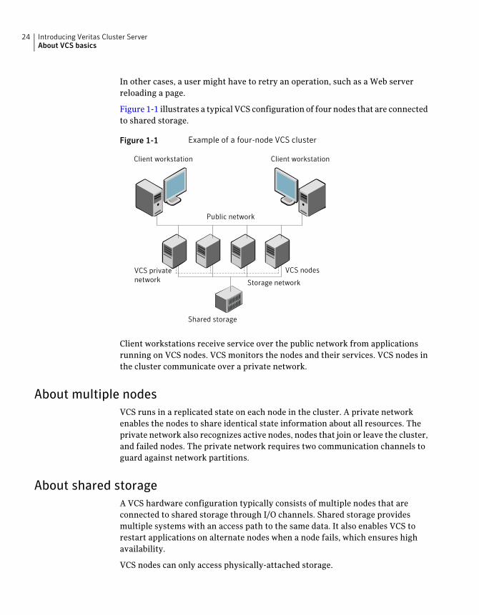
Figure 1-1 illustrates a typical VCS configuration of four nodes that are connectedto shared storage.
Figure 1-1 Example of a four-node VCS cluster
Client workstation Client workstation
Public network
Shared storage
VCS privatenetwork
VCS nodes
Storage network
Client workstations receive service over the public network from applicationsrunning on VCS nodes. VCS monitors the nodes and their services. VCS nodes inthe cluster communicate over a private network.
About multiple nodesVCS runs in a replicated state on each node in the cluster. A private networkenables the nodes to share identical state information about all resources. Theprivate network also recognizes active nodes, nodes that join or leave the cluster,and failed nodes. The private network requires two communication channels toguard against network partitions.
About shared storageA VCS hardware configuration typically consists of multiple nodes that areconnected to shared storage through I/O channels. Shared storage providesmultiple systems with an access path to the same data. It also enables VCS torestart applications on alternate nodes when a node fails, which ensures highavailability.
VCS nodes can only access physically-attached storage.
Introducing Veritas Cluster ServerAbout VCS basics
24
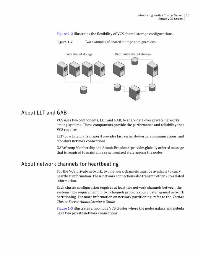
Figure 1-2 illustrates the flexibility of VCS shared storage configurations.
Figure 1-2 Two examples of shared storage configurations
Fully shared storage Distributed shared storage
About LLT and GABVCS uses two components, LLT and GAB, to share data over private networksamong systems. These components provide the performance and reliability thatVCS requires.
LLT (Low Latency Transport) provides fast kernel-to-kernel communications, andmonitors network connections.
GAB (Group Membership and Atomic Broadcast) provides globally ordered messagethat is required to maintain a synchronized state among the nodes.
About network channels for heartbeatingFor the VCS private network, two network channels must be available to carryheartbeat information. These network connections also transmit other VCS-relatedinformation.
Each cluster configuration requires at least two network channels between thesystems. The requirement for two channels protects your cluster against networkpartitioning. For more information on network partitioning, refer to the VeritasCluster Server Administrator's Guide.
Figure 1-3 illustrates a two-node VCS cluster where the nodes galaxy and nebulahave two private network connections.
25Introducing Veritas Cluster ServerAbout VCS basics
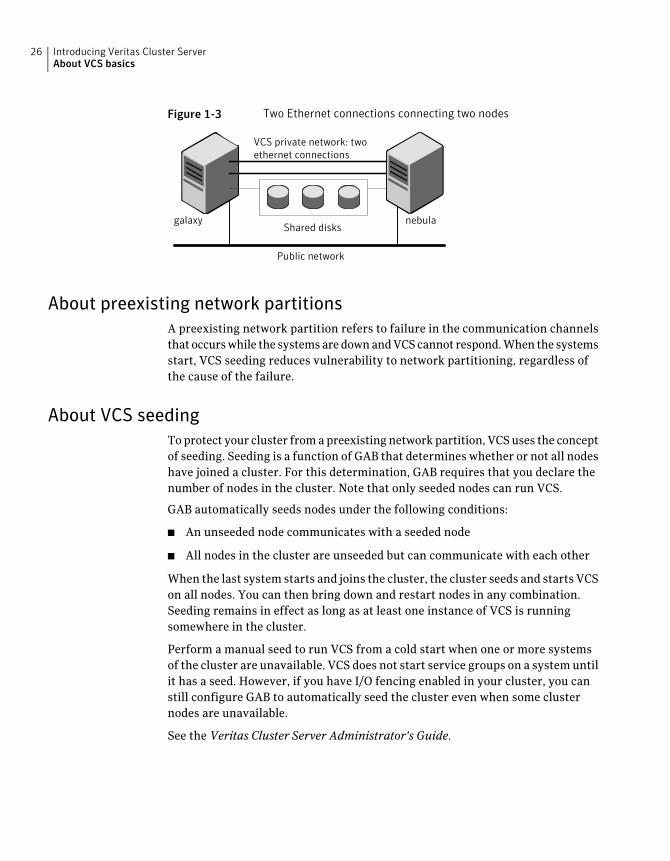
Figure 1-3 Two Ethernet connections connecting two nodes
VCS private network: twoethernet connections
Shared disks
Public network
galaxy nebula
About preexisting network partitionsA preexisting network partition refers to failure in the communication channelsthat occurs while the systems are down and VCS cannot respond. When the systemsstart, VCS seeding reduces vulnerability to network partitioning, regardless ofthe cause of the failure.
About VCS seedingTo protect your cluster from a preexisting network partition, VCS uses the conceptof seeding. Seeding is a function of GAB that determines whether or not all nodeshave joined a cluster. For this determination, GAB requires that you declare thenumber of nodes in the cluster. Note that only seeded nodes can run VCS.
GAB automatically seeds nodes under the following conditions:
■ An unseeded node communicates with a seeded node
■ All nodes in the cluster are unseeded but can communicate with each other
When the last system starts and joins the cluster, the cluster seeds and starts VCSon all nodes. You can then bring down and restart nodes in any combination.Seeding remains in effect as long as at least one instance of VCS is runningsomewhere in the cluster.
Perform a manual seed to run VCS from a cold start when one or more systemsof the cluster are unavailable. VCS does not start service groups on a system untilit has a seed. However, if you have I/O fencing enabled in your cluster, you canstill configure GAB to automatically seed the cluster even when some clusternodes are unavailable.
See the Veritas Cluster Server Administrator's Guide.
Introducing Veritas Cluster ServerAbout VCS basics
26
About VCS featuresVCS offers the following features that you can configure during VCS configuration:
See “About VCS notifications” on page 27.VCS notifications
See “About global clusters” on page 27.VCS global clusters
See “About I/O fencing” on page 27.I/O fencing
About VCS notificationsYou can configure both Simple Network Management Protocol (SNMP) and SimpleMail Transfer Protocol (SMTP) notifications for VCS. Symantec recommends youto configure at least one of these notifications. You have the following options:
■ Configure SNMP trap notification of VCS events using the VCS Notifiercomponent.
■ Configure SMTP email notification of VCS events using the VCS Notifiercomponent.
See the Veritas Cluster Server Administrator’s Guide.
About global clustersGlobal clusters provide the ability to fail over applications between geographicallydistributed clusters when disaster occurs. You require a separate license toconfigure global clusters. You must add this license during the installation. Theinstaller only asks about configuring global clusters if you have used the globalcluster license.
See the Veritas Cluster Server Administrator's Guide.
About I/O fencingI/O fencing protects the data on shared disks when nodes in a cluster detect achange in the cluster membership that indicates a split-brain condition.
The fencing operation determines the following:
■ The nodes that must retain access to the shared storage
■ The nodes that must be ejected from the cluster
This decision prevents possible data corruption. The installer installs the I/Ofencing driver, VRTSvxfen package, when you install VCS. To protect data onshared disks, you must configure I/O fencing after you install and configure VCS.
27Introducing Veritas Cluster ServerAbout VCS features
I/O fencing technology uses coordination points for arbitration in the event of anetwork partition.
I/O fencing coordination points can be coordinator disks or coordination pointservers (CP servers) or both. You can configure disk-based or server-based I/Ofencing:
I/O fencing that uses coordinator disks is referredto as disk-based I/O fencing.
Disk-based I/O fencing ensures data integrity ina single cluster.
Disk-based I/O fencing
I/O fencing that uses at least one CP server systemis referred to as server-based I/O fencing.Server-based fencing can include only CP servers,or a mix of CP servers and coordinator disks.
Server-based I/O fencing ensures data integrityin clusters.
In virtualized environments that do not supportSCSI-3 PR, VCS supports non-SCSI-3 server-basedI/O fencing.
Server-based I/O fencing
See “About planning to configure I/O fencing” on page 95.
Note: Symantec recommends that you use I/O fencing to protect your clusteragainst split-brain situations.
See the Veritas Cluster Server Administrator's Guide.
About VCS optional componentsYou can add the following optional components to VCS:
See “About Veritas Operations Manager” on page 29.Veritas Operations Manager
See “About Cluster Manager (Java Console)” on page 29.
See “About Cluster Manager (Java Console)” on page 29.
Cluster Manager (Java console)
See About VCS Simulator on page 29.VCS Simulator
Introducing Veritas Cluster ServerAbout VCS optional components
28
About Veritas Operations ManagerVeritas Operations Manager provides a centralized management console forVeritas Storage Foundation and High Availability products. You can use VeritasOperations Manager to monitor, visualize, and manage storage resources andgenerate reports.
Symantec recommends using Veritas Operations Manager (VOM) to manageStorage Foundation and Cluster Server environments.
You can download Veritas Operations Manager at no charge athttp://go.symantec.com/vom.
Refer to the Veritas Operations Manager documentation for installation, upgrade,and configuration instructions.
If you want to manage a single cluster using Cluster Manager (Java Console), aversion is available for download from http://go.symantec.com/vcsm_download.You cannot manage the new features of this release using the Java Console. VeritasCluster Server Management Console is deprecated.
About Cluster Manager (Java Console)Cluster Manager (Java Console) offers administration capabilities for your cluster.Use the different views in the Java Console to monitor clusters and VCS objects,including service groups, systems, resources, and resource types. You cannotmanage the new features of releases 6.0 and later using the Java Console.
See Veritas Cluster Server Administrator's Guide.
You can download the console from http://go.symantec.com/vcsm_download.
About VCS SimulatorVCS Simulator enables you to simulate and test cluster configurations. Use VCSSimulator to view and modify service group and resource configurations and testfailover behavior. VCS Simulator can be run on a stand-alone system and doesnot require any additional hardware. You can install VCS Simulator only on aWindows operating system.
VCS Simulator runs an identical version of the VCS High Availability Daemon(HAD) as in a cluster, ensuring that failover decisions are identical to those in anactual cluster.
You can test configurations from different operating systems using VCS Simulator.For example, you can run VCS Simulator to test configurations for VCS clusterson Windows, AIX, HP-UX, Linux, and Solaris operating systems. VCS Simulatoralso enables creating and testing global clusters.
29Introducing Veritas Cluster ServerAbout VCS optional components
You can administer VCS Simulator from the Java Console or from the commandline.
To download VCS Simulator, go to http://go.symantec.com/vcsm_download.
About Symantec Operations Readiness ToolsSymantec Operations Readiness Tools (SORT) is a Web site that automates andsimplifies some of the most time-consuming administrative tasks. SORT helpsyou manage your datacenter more efficiently and get the most out of yourSymantec products.
Among its broad set of features, SORT lets you do the following:
■ Generate server-specific reports that describe how to prepare your servers forinstallation or upgrade of Symantec enterprise products.
■ Access a single site with the latest production information, including patches,agents, and documentation.
■ Create automatic email notifications for changes in patches, documentation,and array-specific modules.
To access SORT, go to:
https://sort.symantec.com
About configuring VCS clusters for data integrityWhen a node fails, VCS takes corrective action and configures its components toreflect the altered membership. If an actual node failure did not occur and if thesymptoms were identical to those of a failed node, then such corrective actionwould cause a split-brain situation.
Some example scenarios that can cause such split-brain situations are as follows:
■ Broken set of private networksIf a system in a two-node cluster fails, the system stops sending heartbeatsover the private interconnects. The remaining node then takes correctiveaction. The failure of the private interconnects, instead of the actual nodes,presents identical symptoms and causes each node to determine its peer hasdeparted. This situation typically results in data corruption because both nodestry to take control of data storage in an uncoordinated manner.
■ System that appears to have a system-hangIf a system is so busy that it appears to stop responding, the other nodes coulddeclare it as dead. This declaration may also occur for the nodes that use thehardware that supports a "break" and "resume" function. When a node drops
Introducing Veritas Cluster ServerAbout Symantec Operations Readiness Tools
30
to PROM level with a break and subsequently resumes operations, the othernodes may declare the system dead. They can declare it dead even if the systemlater returns and begins write operations.
I/O fencing is a feature that prevents data corruption in the event of acommunication breakdown in a cluster. VCS uses I/O fencing to remove the riskthat is associated with split-brain. I/O fencing allows write access for membersof the active cluster. It blocks access to storage from non-members so that evena node that is alive is unable to cause damage.
After you install and configure VCS, you must configure I/O fencing in VCS toensure data integrity.
See “About planning to configure I/O fencing” on page 95.
About I/O fencing for VCS in virtual machines that do not supportSCSI-3 PR
In a traditional I/O fencing implementation, where the coordination points arecoordination point servers (CP servers) or coordinator disks, Veritas ClusteredVolume Manager and Veritas I/O fencing modules provide SCSI-3 persistentreservation (SCSI-3 PR) based protection on the data disks. This SCSI-3 PRprotection ensures that the I/O operations from the losing node cannot reach adisk that the surviving sub-cluster has already taken over.
See theVeritasClusterServerAdministrator'sGuide for more information on howI/O fencing works.
In virtualized environments that do not support SCSI-3 PR, VCS attempts toprovide reasonable safety for the data disks. VCS requires you to configurenon-SCSI-3 server-based I/O fencing in such environments. Non-SCSI-3 fencinguses CP servers as coordination points with some additional configuration changesto support I/O fencing in such environments.
See “Setting up non-SCSI-3 server-based I/O fencing in virtual environmentsusing installvcs program” on page 168.
See “Setting up non-SCSI-3 fencing in virtual environments manually” on page 281.
About I/O fencing componentsThe shared storage for VCS must support SCSI-3 persistent reservations to enableI/O fencing. VCS involves two types of shared storage:
■ Data disks—Store shared dataSee “About data disks” on page 32.
■ Coordination points—Act as a global lock during membership changes
31Introducing Veritas Cluster ServerAbout configuring VCS clusters for data integrity
See “About coordination points” on page 32.
About data disksData disks are standard disk devices for data storage and are either physical disksor RAID Logical Units (LUNs).
These disks must support SCSI-3 PR and must be part of standard VxVM diskgroups. VxVM is responsible for fencing data disks on a disk group basis. Disksthat are added to a disk group and new paths that are discovered for a device areautomatically fenced.
About coordination pointsCoordination points provide a lock mechanism to determine which nodes get tofence off data drives from other nodes. A node must eject a peer from thecoordination points before it can fence the peer from the data drives. VCS preventssplit-brain when vxfen races for control of the coordination points and the winnerpartition fences the ejected nodes from accessing the data disks.
Note:Typically, a fencing configuration for a cluster must have three coordinationpoints. Symantec also supports server-based fencing with a single CP server asits only coordination point with a caveat that this CP server becomes a singlepoint of failure.
The coordination points can either be disks or servers or both.
■ Coordinator disksDisks that act as coordination points are called coordinator disks. Coordinatordisks are three standard disks or LUNs set aside for I/O fencing during clusterreconfiguration. Coordinator disks do not serve any other storage purpose inthe VCS configuration.You can configure coordinator disks to use Veritas Volume Manager DynamicMulti-pathing (DMP) feature. Dynamic Multi-pathing (DMP) allows coordinatordisks to take advantage of the path failover and the dynamic adding andremoval capabilities of DMP. So, you can configure I/O fencing to use eitherDMP devices or the underlying raw character devices. I/O fencing uses SCSI-3disk policy that is either raw or dmp based on the disk device that you use. Thedisk policy is dmp by default.See the Veritas Storage Foundation Administrator’s Guide.
■ Coordination point servers
Introducing Veritas Cluster ServerAbout configuring VCS clusters for data integrity
32
The coordination point server (CP server) is a software solution which runson a remote system or cluster. CP server provides arbitration functionality byallowing the VCS cluster nodes to perform the following tasks:
■ Self-register to become a member of an active VCS cluster (registered withCP server) with access to the data drives
■ Check which other nodes are registered as members of this active VCScluster
■ Self-unregister from this active VCS cluster
■ Forcefully unregister other nodes (preempt) as members of this active VCScluster
In short, the CP server functions as another arbitration mechanism thatintegrates within the existing I/O fencing module.
Note:With the CP server, the fencing arbitration logic still remains on the VCScluster.
Multiple VCS clusters running different operating systems can simultaneouslyaccess the CP server. TCP/IP based communication is used between the CPserver and the VCS clusters.
About preferred fencingThe I/O fencing driver uses coordination points to prevent split-brain in a VCScluster. By default, the fencing driver favors the subcluster with maximum numberof nodes during the race for coordination points. With the preferred fencingfeature, you can specify how the fencing driver must determine the survivingsubcluster.
You can configure the preferred fencing policy using the cluster-level attributePreferredFencingPolicy for the following:
■ Enable system-based preferred fencing policy to give preference to highcapacity systems.
■ Enable group-based preferred fencing policy to give preference to servicegroups for high priority applications.
■ Disable preferred fencing policy to use the default node count-based racepolicy.
See the Veritas Cluster Server Administrator's Guide for more details.
See “Enabling or disabling the preferred fencing policy” on page 170.
33Introducing Veritas Cluster ServerAbout configuring VCS clusters for data integrity

Introducing Veritas Cluster ServerAbout configuring VCS clusters for data integrity
34
System requirements
This chapter includes the following topics:
■ Important preinstallation information for VCS
■ Hardware requirements for VCS
■ Disk space requirements
■ Supported operating systems
■ Supported software for VCS
■ I/O fencing requirements
■ Number of nodes supported
■ Discovering product versions and various requirement information
Important preinstallation information for VCSBefore you install VCS, make sure that you have reviewed the followinginformation:
■ The hardware compatibility list contains information about supported hardwareand is updated regularly. For the latest information on supported hardwarevisit the following URL:http://www.symantec.com/docs/TECH170013Before installing or upgrading VCS, review the current compatibility list toconfirm the compatibility of your hardware and software.
■ For important updates regarding this release, review the Late-Breaking NewsTechNote on the Symantec Technical Support website:http://www.symantec.com/docs/TECH164885
■ You can install VCS on clusters of up to 64 systems.
2Chapter
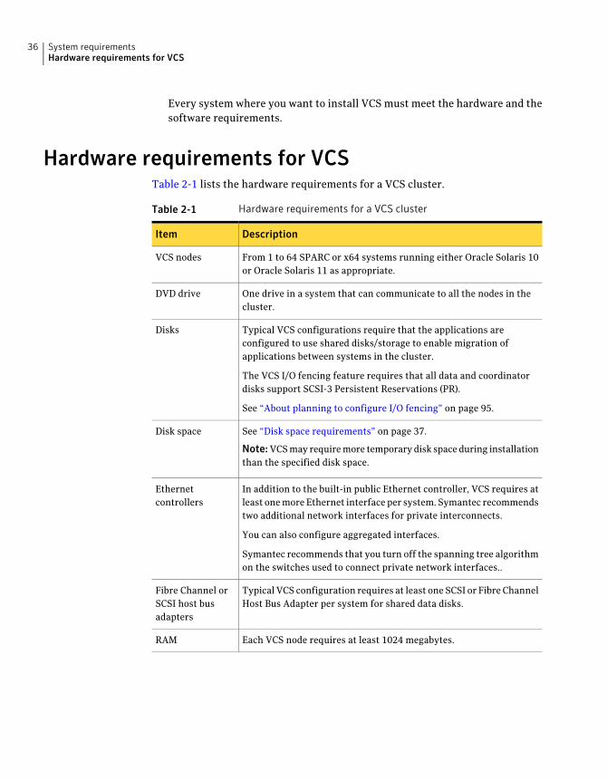
Every system where you want to install VCS must meet the hardware and thesoftware requirements.
Hardware requirements for VCSTable 2-1 lists the hardware requirements for a VCS cluster.
Table 2-1 Hardware requirements for a VCS cluster
DescriptionItem
From 1 to 64 SPARC or x64 systems running either Oracle Solaris 10or Oracle Solaris 11 as appropriate.
VCS nodes
One drive in a system that can communicate to all the nodes in thecluster.
DVD drive
Typical VCS configurations require that the applications areconfigured to use shared disks/storage to enable migration ofapplications between systems in the cluster.
The VCS I/O fencing feature requires that all data and coordinatordisks support SCSI-3 Persistent Reservations (PR).
See “About planning to configure I/O fencing” on page 95.
Disks
See “Disk space requirements” on page 37.
Note:VCS may require more temporary disk space during installationthan the specified disk space.
Disk space
In addition to the built-in public Ethernet controller, VCS requires atleast one more Ethernet interface per system. Symantec recommendstwo additional network interfaces for private interconnects.
You can also configure aggregated interfaces.
Symantec recommends that you turn off the spanning tree algorithmon the switches used to connect private network interfaces..
Ethernetcontrollers
Typical VCS configuration requires at least one SCSI or Fibre ChannelHost Bus Adapter per system for shared data disks.
Fibre Channel orSCSI host busadapters
Each VCS node requires at least 1024 megabytes.RAM
System requirementsHardware requirements for VCS
36
Disk space requirementsBefore installing your products, confirm that your system has enough free diskspace.
Use the "Perform a Pre-installation Check" (P) menu for the Web-based installeror the - precheck option of the script-based installer to determine whether thereis sufficient space.
Go to the installation directory and run the installer with the -precheck option.
# ./installer -precheck
If you have downloaded VCS, you must use the following command:
# ./installvcs program -precheck<version>
Where <version> is the specific release version.
See “About the Veritas installer” on page 46.
Supported operating systemsFor information on supported operating systems, see the Veritas Cluster ServerRelease Notes.
Supported software for VCSVCS supports the following versions of Veritas Storage Foundation:
Veritas Storage Foundation: Veritas Volume Manager (VxVM) with Veritas FileSystem (VxFS)
Oracle Solaris 11
■ Storage Foundation 6.0.1
■ Storage Foundation 6.0PR1
Oracle Solaris 10
■ Storage Foundation 6.0.1
■ Storage Foundation 6.0PR1
Note: VCS supports the previous and the next versions of Storage Foundation tofacilitate product upgrades.
37System requirementsDisk space requirements
I/O fencing requirementsDepending on whether you plan to configure disk-based fencing or server-basedfencing, make sure that you meet the requirements for coordination points:
■ Coordinator disksSee “Coordinator disk requirements for I/O fencing” on page 38.
■ CP serversSee “CP server requirements” on page 38.
To configure disk-based fencing or to configure server-based fencing with at leastone coordinator disk, make sure a version of Veritas Volume Manager (VxVM)that supports SCSI-3 persistent reservations (SCSI-3 PR) is installed on the VCScluster.
See the Veritas Storage Foundation and High Availability Installation Guide.
If you have installed VCS in a virtual environment that is not SCSI-3 PR compliant,review the requirements to configure non-SCSI-3 server-based fencing.
See “Non-SCSI-3 I/O fencing requirements” on page 42.
Coordinator disk requirements for I/O fencingMake sure that the I/O fencing coordinator disks meet the following requirements:
■ For disk-based I/O fencing, you must have at least three coordinator disks orthere must be odd number of coordinator disks.
■ The coordinator disks can be raw devices, DMP devices, or iSCSI devices.
■ Each of the coordinator disks must use a physically separate disk or LUN.Symantec recommends using the smallest possible LUNs for coordinator disks.
■ Each of the coordinator disks should exist on a different disk array, if possible.
■ The coordinator disks must support SCSI-3 persistent reservations.
■ Symantec recommends using hardware-based mirroring for coordinator disks.
■ Coordinator disks must not be used to store data or must not be included indisk groups that store user data.
■ Coordinator disks cannot be the special devices that array vendors use. Forexample, you cannot use EMC gatekeeper devices as coordinator disks.
CP server requirementsVCS 6.0.1 clusters (application clusters) support coordination point servers (CPservers) which are hosted on the following VCS and SFHA versions:
System requirementsI/O fencing requirements
38
■ VCS 6.0.1, VCS 6.0, VCS 6.0 PR1, VCS 6.0 RP1, VCS 5.1SP1, or VCS 5.1single-node clusterSingle-node VCS clusters with VCS 5.1 SP1 RP1 and later or VCS 6.0 and laterthat hosts CP server does not require LLT and GAB to be configured.
■ SFHA 6.0.1, SFHA 6.0, SFHA 6.0 PR1, SFHA 6.0 RP1, 5.1SP1, or 5.1 cluster
Warning: Before you upgrade 5.1 CP server nodes to use VCS or SFHA 6.0.1, youmust upgrade all the application clusters that use this CP server to version 6.0.1.Application clusters at version 5.1 cannot communicate with CP server that runsVCS or SFHA 5.1 SP1 or later.
Make sure that you meet the basic hardware requirements for the VCS/SFHAcluster to host the CP server.
See the Veritas Storage Foundation High Availability Installation Guide.
See “Hardware requirements for VCS” on page 36.
Note:While Symantec recommends at least three coordination points for fencing,a single CP server as coordination point is a supported server-based fencingconfiguration. Such single CP server fencing configuration requires that thecoordination point be a highly available CP server that is hosted on an SFHAcluster.
Make sure you meet the following additional CP server requirements which arecovered in this section before you install and configure CP server:
■ Hardware requirements
■ Operating system requirements
■ Networking requirements (and recommendations)
■ Security requirements
Table 2-2 lists additional requirements for hosting the CP server.
39System requirementsI/O fencing requirements
Table 2-2 CP server hardware requirements
DescriptionHardware required
To host the CP server on a VCS cluster or SFHA cluster, eachhost requires the following file system space:
■ 550 MB in the /opt directory (additionally, the languagepack requires another 15 MB)
■ 300 MB in /usr
■ 20 MB in /var
■ 10 MB in /etc (for the CP server database)
See “Disk space requirements” on page 37.
Disk space
When CP server is hosted on an SFHA cluster, there mustbe shared storage between the nodes of this SFHA cluster.
Storage
Each CP server requires at least 512 MB.RAM
Network hardware capable of providing TCP/IP connectionbetween CP servers and VCS clusters (application clusters).
Network
Table 2-3 displays the CP server supported operating systems and versions. Anapplication cluster can use a CP server that runs any of the following supportedoperating systems.
Table 2-3 CP server supported operating systems and versions
Operating system and versionCP server
CP server supports any of the following operating systems:
■ AIX 6.1 and 7.1
■ HP-UX 11i v3
■ Linux:
■ RHEL 5
■ RHEL 6
■ SLES 10
■ SLES 11
■ Oracle Solaris 10
■ Oracle Solaris 11
Review other details such as supported operating systemlevels and architecture for the supported operating systems.
See the Veritas Cluster Server Release Notes or the VeritasStorage FoundationHigh Availability Release Notes for thatplatform.
CP server hosted on a VCSsingle-node cluster or on anSFHA cluster
System requirementsI/O fencing requirements
40
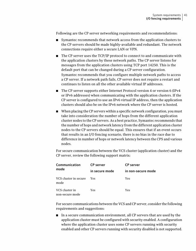
Following are the CP server networking requirements and recommendations:
■ Symantec recommends that network access from the application clusters tothe CP servers should be made highly-available and redundant. The networkconnections require either a secure LAN or VPN.
■ The CP server uses the TCP/IP protocol to connect to and communicate withthe application clusters by these network paths. The CP server listens formessages from the application clusters using TCP port 14250. This is thedefault port that can be changed during a CP server configuration.Symantec recommends that you configure multiple network paths to accessa CP server. If a network path fails, CP server does not require a restart andcontinues to listen on all the other available virtual IP addresses.
■ The CP server supports either Internet Protocol version 4 or version 6 (IPv4or IPv6 addresses) when communicating with the application clusters. If theCP server is configured to use an IPv6 virtual IP address, then the applicationclusters should also be on the IPv6 network where the CP server is hosted.
■ When placing the CP servers within a specific network configuration, you musttake into consideration the number of hops from the different applicationcluster nodes to the CP servers. As a best practice, Symantec recommends thatthe number of hops and network latency from the different application clusternodes to the CP servers should be equal. This ensures that if an event occursthat results in an I/O fencing scenario, there is no bias in the race due todifference in number of hops or network latency between the CPS and variousnodes.
For secure communication between the VCS cluster (application cluster) and theCP server, review the following support matrix:
CP server
in non-secure mode
CP server
in secure mode
Communicationmode
YesYesVCS cluster in securemode
YesYesVCS cluster innon-secure mode
For secure communications between the VCS and CP server, consider the followingrequirements and suggestions:
■ In a secure communication environment, all CP servers that are used by theapplication cluster must be configured with security enabled. A configurationwhere the application cluster uses some CP servers running with securityenabled and other CP servers running with security disabled is not supported.
41System requirementsI/O fencing requirements
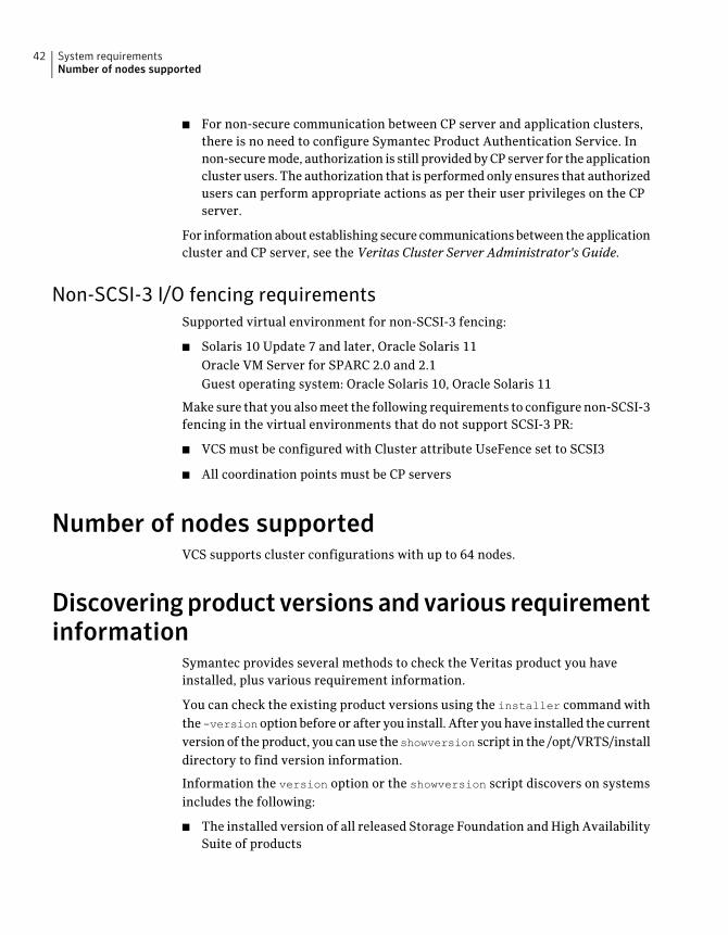
■ For non-secure communication between CP server and application clusters,there is no need to configure Symantec Product Authentication Service. Innon-secure mode, authorization is still provided by CP server for the applicationcluster users. The authorization that is performed only ensures that authorizedusers can perform appropriate actions as per their user privileges on the CPserver.
For information about establishing secure communications between the applicationcluster and CP server, see the Veritas Cluster Server Administrator's Guide.
Non-SCSI-3 I/O fencing requirementsSupported virtual environment for non-SCSI-3 fencing:
■ Solaris 10 Update 7 and later, Oracle Solaris 11Oracle VM Server for SPARC 2.0 and 2.1Guest operating system: Oracle Solaris 10, Oracle Solaris 11
Make sure that you also meet the following requirements to configure non-SCSI-3fencing in the virtual environments that do not support SCSI-3 PR:
■ VCS must be configured with Cluster attribute UseFence set to SCSI3
■ All coordination points must be CP servers
Number of nodes supportedVCS supports cluster configurations with up to 64 nodes.
Discoveringproduct versionsandvarious requirementinformation
Symantec provides several methods to check the Veritas product you haveinstalled, plus various requirement information.
You can check the existing product versions using the installer command withthe -versionoption before or after you install. After you have installed the currentversion of the product, you can use theshowversion script in the /opt/VRTS/installdirectory to find version information.
Information the version option or the showversion script discovers on systemsincludes the following:
■ The installed version of all released Storage Foundation and High AvailabilitySuite of products
System requirementsNumber of nodes supported
42
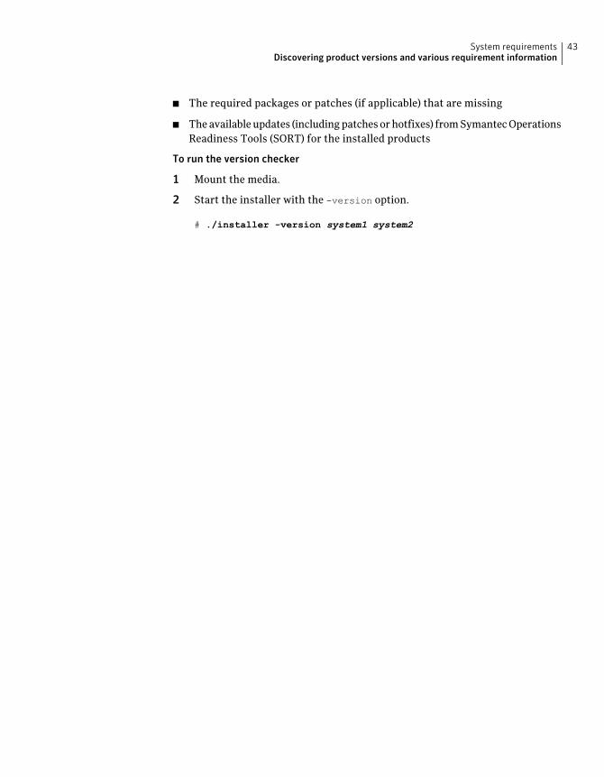
■ The required packages or patches (if applicable) that are missing
■ The available updates (including patches or hotfixes) from Symantec OperationsReadiness Tools (SORT) for the installed products
To run the version checker
1 Mount the media.
2 Start the installer with the -version option.
# ./installer -version system1 system2
43System requirementsDiscovering product versions and various requirement information

System requirementsDiscovering product versions and various requirement information
44
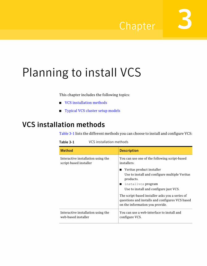
Planning to install VCS
This chapter includes the following topics:
■ VCS installation methods
■ Typical VCS cluster setup models
VCS installation methodsTable 3-1 lists the different methods you can choose to install and configure VCS:
Table 3-1 VCS installation methods
DescriptionMethod
You can use one of the following script-basedinstallers:
■ Veritas product installer
Use to install and configure multiple Veritasproducts.
■ installvcs program
Use to install and configure just VCS.
The script-based installer asks you a series ofquestions and installs and configures VCS basedon the information you provide.
Interactive installation using thescript-based installer
You can use a web-interface to install andconfigure VCS.
Interactive installation using theweb-based installer
3Chapter
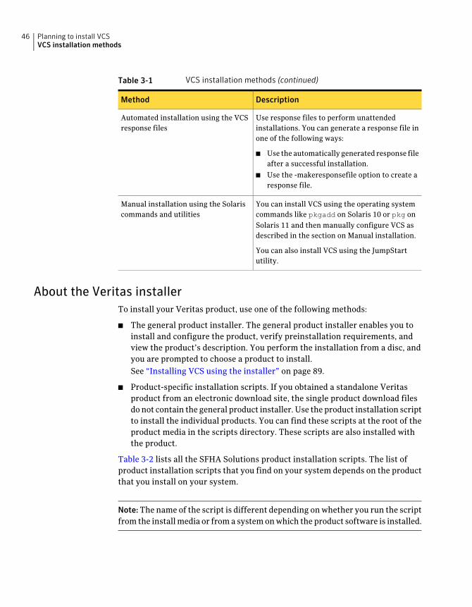
Table 3-1 VCS installation methods (continued)
DescriptionMethod
Use response files to perform unattendedinstallations. You can generate a response file inone of the following ways:
■ Use the automatically generated response fileafter a successful installation.
■ Use the -makeresponsefile option to create aresponse file.
Automated installation using the VCSresponse files
You can install VCS using the operating systemcommands like pkgadd on Solaris 10 or pkg onSolaris 11 and then manually configure VCS asdescribed in the section on Manual installation.
You can also install VCS using the JumpStartutility.
Manual installation using the Solariscommands and utilities
About the Veritas installerTo install your Veritas product, use one of the following methods:
■ The general product installer. The general product installer enables you toinstall and configure the product, verify preinstallation requirements, andview the product’s description. You perform the installation from a disc, andyou are prompted to choose a product to install.See “Installing VCS using the installer” on page 89.
■ Product-specific installation scripts. If you obtained a standalone Veritasproduct from an electronic download site, the single product download filesdo not contain the general product installer. Use the product installation scriptto install the individual products. You can find these scripts at the root of theproduct media in the scripts directory. These scripts are also installed withthe product.
Table 3-2 lists all the SFHA Solutions product installation scripts. The list ofproduct installation scripts that you find on your system depends on the productthat you install on your system.
Note:The name of the script is different depending on whether you run the scriptfrom the install media or from a system on which the product software is installed.
Planning to install VCSVCS installation methods
46
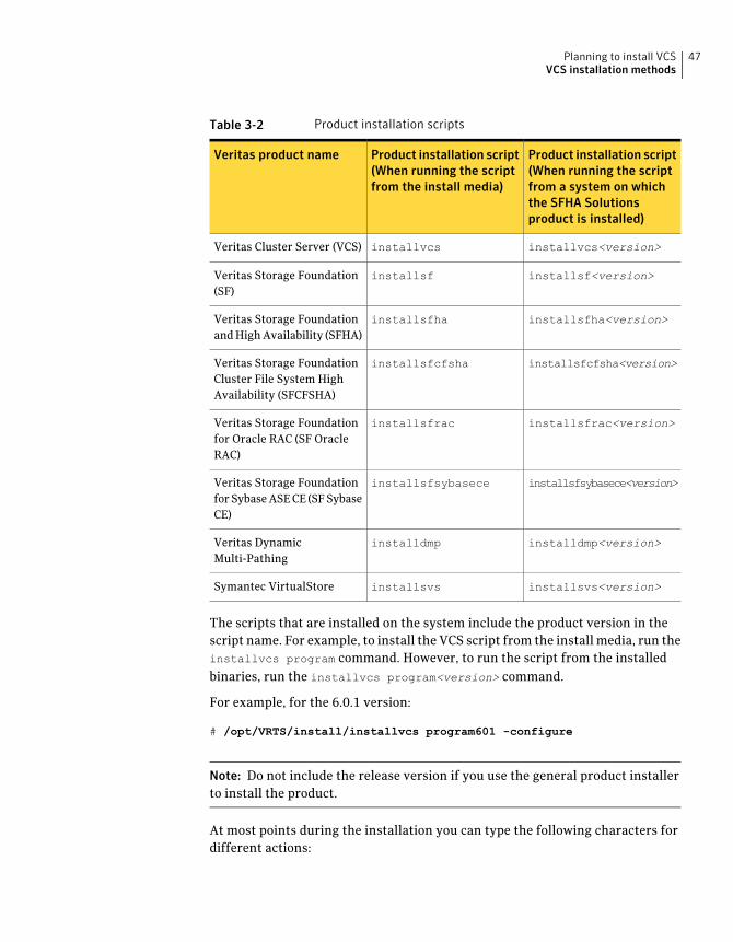
Table 3-2 Product installation scripts
Product installation script(When running the scriptfrom a system on whichthe SFHA Solutionsproduct is installed)
Product installation script(When running the scriptfrom the install media)
Veritas product name
installvcs<version>installvcsVeritas Cluster Server (VCS)
installsf<version>installsfVeritas Storage Foundation(SF)
installsfha<version>installsfhaVeritas Storage Foundationand High Availability (SFHA)
installsfcfsha<version>installsfcfshaVeritas Storage FoundationCluster File System HighAvailability (SFCFSHA)
installsfrac<version>installsfracVeritas Storage Foundationfor Oracle RAC (SF OracleRAC)
installsfsybasece<version>installsfsybaseceVeritas Storage Foundationfor Sybase ASE CE (SF SybaseCE)
installdmp<version>installdmpVeritas DynamicMulti-Pathing
installsvs<version>installsvsSymantec VirtualStore
The scripts that are installed on the system include the product version in thescript name. For example, to install the VCS script from the install media, run theinstallvcs program command. However, to run the script from the installedbinaries, run the installvcs program<version> command.
For example, for the 6.0.1 version:
# /opt/VRTS/install/installvcs program601 -configure
Note: Do not include the release version if you use the general product installerto install the product.
At most points during the installation you can type the following characters fordifferent actions:
47Planning to install VCSVCS installation methods
■ Use b (back) to return to a previous section of the installation procedure. Theback feature of the installation scripts is context-sensitive, so it returns to thebeginning of a grouped section of questions.
■ Use Control+c to stop and exit the program if an installation procedure hangs.After a short delay, the script exits.
■ Use q to quit the installer.
■ Use ? to display help information.
■ Use the Enter button to accept a default response.
See “Installation script options” on page 453.
About the VCS installation programYou can access the installvcs program from the command line or through theVeritas product installer.
The VCS installation program is interactive and manages the following tasks:
■ Licensing VCS
■ Installing VCS packages on multiple cluster systems
■ Configuring VCS, by creating several detailed configuration files on eachsystem
■ Starting VCS processes
You can choose to configure different optional features, such as the following:
■ SNMP and SMTP notification
■ VCS configuration in secure mode
■ The wide area Global Cluster feature
■ Cluster Virtual IP address
Review the highlights of the information for which installvcs program promptsyou as you proceed to configure.
See “About preparing to install VCS” on page 63.
The uninstallvcs program, a companion to installvcs program, uninstalls VCSpackages.
See “Preparing to uninstall VCS” on page 425.
Planning to install VCSVCS installation methods
48

Features of the script-based installerThe script-based installer supports installing, configuring, upgrading, anduninstalling VCS. In addition, the script-based installer also provides commandoptions to perform the following tasks:
■ Check the systems for VCS installation requirements.See “Performing automated preinstallation check” on page 77.
■ Upgrade VCS if a previous version of VCS currently runs on a cluster.See “Upgrading VCS using the script-based installer” on page 297.
■ Start or stop VCS processesSee “Starting and stopping processes for the Veritas products ” on page 532.
■ Enable or disable a cluster to run in secure modeSee the Veritas Cluster Server Administrator’s Guide.
■ Configure I/O fencing for the clusters to prevent data corruptionSee “Setting up disk-based I/O fencing using installvcs program” on page 151.See “Setting up server-based I/O fencing using installvcs program” on page 159.See “Setting up non-SCSI-3 server-based I/O fencing in virtual environmentsusing installvcs program” on page 168.
■ Create a single-node clusterSee “Creating a single-node cluster using the installer program” on page 504.
■ Add a node to an existing clusterSee “Adding nodes using the VCS installer” on page 395.
■ Create a jumpstart finish script to install VCS using the JumpStart utility.See “Installing VCS on Solaris 10 using JumpStart” on page 238.
■ Perform automated installations using the values that are stored in aconfiguration file.See “Installing VCS using response files” on page 197.See “Configuring VCS using response files” on page 203.See “Upgrading VCS using response files” on page 323.
Interacting with the installvcs programAs you run the program, you are prompted to answer yes or no questions. A setof responses that resemble [y, n, q, ?] (y) typically follow these questions. Theresponse within parentheses is the default, which you can select by pressing theEnter key. Enter the ? character to get help to answer the prompt. Enter q to quitthe installation.
49Planning to install VCSVCS installation methods
Installation of VCS packages takes place only after you have confirmed theinformation. However, you must remove the partially installed VCS files beforeyou run the installvcs program again.
See “Preparing to uninstall VCS” on page 425.
During the installation, the installer prompts you to type information. The installerexpects your responses to be within a certain range or in a specific format. Theinstaller provides examples. If you are prompted to enter an item from a list, enteryour selection exactly as it is shown in the list.
The installer also prompts you to answer a series of questions that are related toa configuration activity. For such questions, you can enter the b character toreturn to the first prompt in the series. When the installer displays a set ofinformation items you have entered, you are prompted to confirm it. If you answern, the program lets you reenter all of the information for the set.
You can install the VCS Java Console on a single system, which is not required tobe part of the cluster. Note that the installvcs program does not install the VCSJava Console.
See “Installing the Java Console” on page 367.
About the Web-based installerUse the Web-based installer interface to install Veritas products. The Web-basedinstaller can perform most of the tasks that the script-based installer performs.
You use the webinstaller script to start and stop the Veritas XPortal Serverxprtlwid process. The webinstaller script can also be used to check the statusof the XPortal Server.
When the webinstaller script starts the xprtlwid process, the script displays aURL. Use this URL to access the Web-based installer from a Web browser such asInternet Explorer or FireFox.
The Web installer creates log files whenever the Web installer is operating. Whilethe installation processes are operating, the log files are located in a session-baseddirectory under the /var/tmp directory. After the install process completes, thelog files are located in the /opt/VRTS/install/logs directory. It is recommendedthat you keep these files for auditing, debugging, and future use.
The location of the Veritas XPortal Server configuration file is/var/opt/webinstaller/xprtlwid.conf.
See “Before using the Veritas Web-based installer” on page 175.
See “Starting the Veritas Web-based installer” on page 176.
Planning to install VCSVCS installation methods
50
About response filesThe installer generates a "response file" after performing an installer task suchas installation, configuration, uninstallation, or upgrade. These response filescontain the details that you provided to the installer questions in the form ofvalues for the response file variables. The response file also contains descriptionsand explanations of the variables and their values.
You can also create a response file using the -makeresponsefile option of theinstaller.
The installer displays the location of the response file at the end of each successfulinstaller task. The installer saves the response file in the default location for theinstall-related log files: /opt/VRTS/install/logs. If you provided a different logpath using the -logpath option, the installer saves the response file in the paththat you specified.
The format of the response file name is:/opt/VRTS/install/logs/installscript-YYYYMMDDHHSSxxx/installscript-YYYYMMDDHHSSxxx.response, where:
■ installscript may be, for example: installer, webinstaller, installvcs program,or uninstallvcs program
■ YYYYMMDDHHSS is the current date when the installscript is run and xxx arethree random letters that the script generates for an installation instance
For example:/opt/VRTS/install/logs/installer-200910101010ldS/installer-200910101010ldS.response
You can customize the response file as required to perform unattendedinstallations using the -responsefile option of the installer. This method ofautomated installations is useful in the following cases:
■ To perform multiple installations to set up a large VCS cluster.See “Installing VCS using response files” on page 197.
■ To upgrade VCS on multiple systems in a large VCS cluster.See “Upgrading VCS using response files” on page 323.
■ To uninstall VCS from multiple systems in a large VCS cluster.See “Uninstalling VCS using response files” on page 431.
Syntax in the response fileThe syntax of the Perl statements that are included in the response file variablesvaries. It can depend on whether the variables require scalar or list values.
For example, in the case of a string value:
51Planning to install VCSVCS installation methods
$CFG{Scalar_variable}="value";
or, in the case of an integer value:
$CFG{Scalar_variable}=123;
or, in the case of a list:
$CFG{List_variable}=["value", "value", "value"];
Typical VCS cluster setup modelsVCS clusters support different failover configurations, storage configurations,and cluster topologies.
See the Veritas Cluster Server Administrator's Guide for more details.
Some of the typical VCS setup models are as follows:
■ Basic VCS cluster with two nodesSee “Typical configuration of two-node VCS cluster” on page 52.
■ VCS clusters in secure modeSee “Typical configuration of VCS clusters in secure mode” on page 53.
■ VCS clusters centrally managed using Veritas Operations Manager (VOM)See “Typical configuration of VOM-managed VCS clusters” on page 54.
■ VCS clusters with I/O fencing for data protectionSee “Typical VCS cluster configuration with disk-based I/O fencing” on page 99.See “Typical VCS cluster configuration with server-based I/O fencing”on page 100.
■ VCS clusters such as global clusters, replicated data clusters, or campus clustersfor disaster recoverySee the Veritas Cluster Server Administrator's Guide for disaster recoverycluster configuration models.
Typical configuration of two-node VCS clusterFigure 3-1 illustrates a simple VCS cluster setup with two Solaris SPARC systems.
Planning to install VCSTypical VCS cluster setup models
52
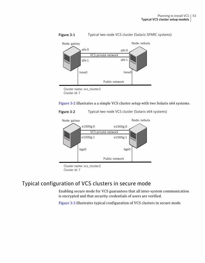
Figure 3-1 Typical two-node VCS cluster (Solaris SPARC systems)
Node: galaxy
Cluster name: vcs_cluster2Cluster id: 7
VCS private network
Public network
qfe:0 qfe:0
qfe:1qfe:1
hme0 hme0
Node: nebula
Figure 3-2 illustrates a a simple VCS cluster setup with two Solaris x64 systems.
Figure 3-2 Typical two-node VCS cluster (Solaris x64 systems)
Node: galaxy
Cluster name: vcs_cluster2Cluster id: 7
VCS private network
Public network
e1000g:0
bge0 bge0
Node: nebula
e1000g:0
e1000g:1 e1000g:1
Typical configuration of VCS clusters in secure modeEnabling secure mode for VCS guarantees that all inter-system communicationis encrypted and that security credentials of users are verified.
Figure 3-3 illustrates typical configuration of VCS clusters in secure mode.
53Planning to install VCSTypical VCS cluster setup models
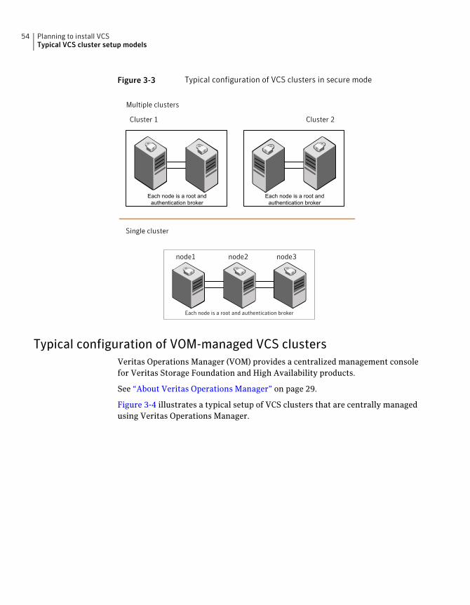
Figure 3-3 Typical configuration of VCS clusters in secure mode
Cluster 1 Cluster 2
node1 node2 node3
Multiple clusters
Single cluster
Each node is a root and authentication broker
Each node is a root andauthentication broker
Each node is a root andauthentication broker
Typical configuration of VOM-managed VCS clustersVeritas Operations Manager (VOM) provides a centralized management consolefor Veritas Storage Foundation and High Availability products.
See “About Veritas Operations Manager” on page 29.
Figure 3-4 illustrates a typical setup of VCS clusters that are centrally managedusing Veritas Operations Manager.
Planning to install VCSTypical VCS cluster setup models
54
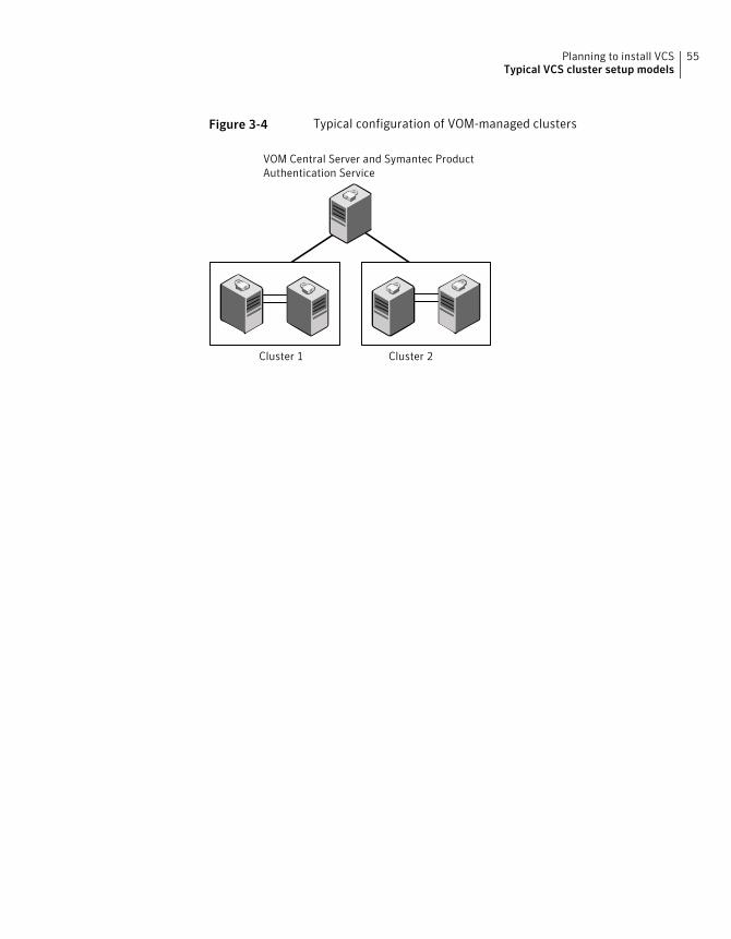
Figure 3-4 Typical configuration of VOM-managed clusters
Cluster 1 Cluster 2
VOM Central Server and Symantec ProductAuthentication Service
55Planning to install VCSTypical VCS cluster setup models

Planning to install VCSTypical VCS cluster setup models
56

Licensing VCS
This chapter includes the following topics:
■ About Veritas product licensing
■ Obtaining VCS license keys
■ Installing Veritas product license keys
About Veritas product licensingYou have the option to install Veritas products without a license key. Installationwithout a license does not eliminate the need to obtain a license. A software licenseis a legal instrument governing the usage or redistribution of copyright protectedsoftware. The administrator and company representatives must ensure that aserver or cluster is entitled to the license level for the products installed. Symantecreserves the right to ensure entitlement and compliance through auditing.
If you encounter problems while licensing this product, visit the Symanteclicensing support website.
www.symantec.com/techsupp/
The Veritas product installer prompts you to select one of the following licensingmethods:
■ Install a license key for the product and features that you want to install.When you purchase a Symantec product, you receive a License Key certificate.The certificate specifies the product keys and the number of product licensespurchased.
■ Continue to install without a license key.The installer prompts for the product modes and options that you want toinstall, and then sets the required product level.
4Chapter
Within 60 days of choosing this option, you must install a valid license keycorresponding to the license level entitled. If you do not comply with the aboveterms, continuing to use the Symantec product is a violation of your end userlicense agreement, and results in warning messages.For more information about keyless licensing, see the following URL:http://go.symantec.com/sfhakeyless
If you upgrade to this release from a prior release of the Veritas software, theinstaller asks whether you want to upgrade the key to the new version. The existinglicense keys may not activate new features in this release.
If you upgrade with the product installer, or if you install or upgrade with a methodother than the product installer, you must do one of the following to license theproducts:
■ Run the vxkeyless command to set the product level for the products youhave purchased. This option also requires that you manage the server or clusterwith a management server.See “Setting or changing the product level for keyless licensing” on page 236.See the vxkeyless(1m) manual page.
■ Use the vxlicinst command to install a valid product license key for theproducts you have purchased.See “Installing Veritas product license keys” on page 59.See the vxlicinst(1m) manual page.
You can also use the above options to change the product levels to another levelthat you are authorized to use. For example, you can add the replication optionto the installed product. You must ensure that you have the appropriate licensefor the product level and options in use.
Note: In order to change from one product group to another, you may need toperform additional steps.
Obtaining VCS license keysIf you decide to not use the keyless licensing, you must obtain and install a licensekey for VCS.
See “About Veritas product licensing” on page 57.
This product includes a License Key certificate. The certificate specifies the productkeys and the number of product licenses purchased. A single key lets you installthe product on the number and type of systems for which you purchased thelicense. A key may enable the operation of more products than are specified on
Licensing VCSObtaining VCS license keys
58
the certificate. However, you are legally limited to the number of product licensespurchased. The product installation procedure describes how to activate the key.
To register and receive a software license key, go to the Symantec Licensing Portalat the following location:
https://licensing.symantec.com
Make sure you have your Software Product License document. You needinformation in this document to retrieve and manage license keys for yourSymantec product. After you receive the license key, you can install the product.
Click the Help link at this site to access the License Portal User Guide and FAQ.
The VRTSvlic package enables product licensing. For information about thecommands that you can use after the installing VRTSvlic:
See “Installing Veritas product license keys” on page 59.
You can only install the Symantec software products for which you have purchaseda license. The enclosed software discs might include other products for which youhave not purchased a license.
Installing Veritas product license keysThe VRTSvlic package enables product licensing. After the VRTSvlic is installed,the following commands and their manual pages are available on the system:
Installs a license key for a Symantec productvxlicinst
Displays currently installed licensesvxlicrep
Retrieves features and their descriptionsencoded in a license key
vxlictest
Even though other products are included on the enclosed software discs, you canonly use the Symantec software products for which you have purchased a license.
To install a new license
◆ Run the following commands. In a cluster environment, run the commandson each node in the cluster:
# cd /opt/VRTS/bin
# ./vxlicinst -k license key
To see a list of your vxkeyless keys, enter the following command:
59Licensing VCSInstalling Veritas product license keys

# ./vxkeyless display
After you upgrade from a previous release, the output you see when you run thevxkeyless display command includes the previous release's vxkeyless keys.Each vxkeyless key name includes the suffix _<previous_release_version>. Forexample, DMP_6.0, or SFENT_VR_5.1SP1, or VCS_GCO_5.1. During the upgradeprocess, the CPI installer prompts you to update the vxkeyless keys to the currentrelease level. If you update the vxkeyless keys during the upgrade process, youno longer see the _<previous_release_number> suffix after the keys are updated.
Licensing VCSInstalling Veritas product license keys
60
Preinstallation tasks
■ Chapter 5. Preparing to install VCS
2Section

62
Preparing to install VCS
This chapter includes the following topics:
■ About preparing to install VCS
■ Performing preinstallation tasks
■ Getting your VCS installation and configuration information ready
■ Making the IPS publisher accessible
About preparing to install VCSBefore you perform the preinstallation tasks, make sure you reviewed theinstallation requirements, set up the basic hardware, and planned your VCS setup.
See “Important preinstallation information for VCS” on page 35.
Performing preinstallation tasksTable 5-1 lists the tasks you must perform before proceeding to install VCS.
Table 5-1 Preinstallation tasks
ReferenceTask
See “Obtaining VCS license keys” on page 58.Obtain license keys ifyou do not want to usekeyless licensing.
See “Setting up the private network” on page 64.Set up the privatenetwork.
See “Setting up inter-system communication” on page 525.Enable communicationbetween systems.
5Chapter
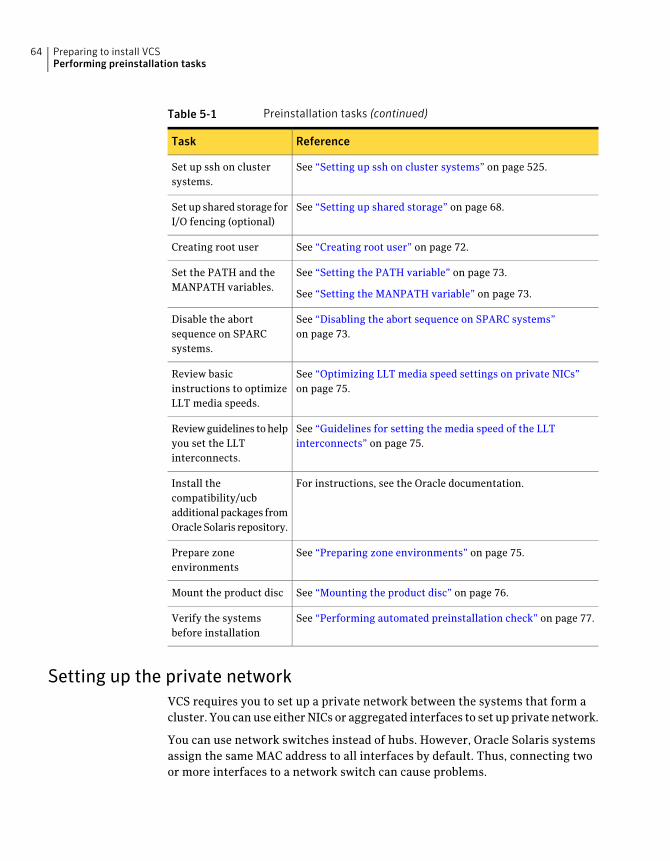
Table 5-1 Preinstallation tasks (continued)
ReferenceTask
See “Setting up ssh on cluster systems” on page 525.Set up ssh on clustersystems.
See “Setting up shared storage” on page 68.Set up shared storage forI/O fencing (optional)
See “Creating root user” on page 72.Creating root user
See “Setting the PATH variable” on page 73.
See “Setting the MANPATH variable” on page 73.
Set the PATH and theMANPATH variables.
See “Disabling the abort sequence on SPARC systems”on page 73.
Disable the abortsequence on SPARCsystems.
See “Optimizing LLT media speed settings on private NICs”on page 75.
Review basicinstructions to optimizeLLT media speeds.
See “Guidelines for setting the media speed of the LLTinterconnects” on page 75.
Review guidelines to helpyou set the LLTinterconnects.
For instructions, see the Oracle documentation.Install thecompatibility/ucbadditional packages fromOracle Solaris repository.
See “Preparing zone environments” on page 75.Prepare zoneenvironments
See “Mounting the product disc” on page 76.Mount the product disc
See “Performing automated preinstallation check” on page 77.Verify the systemsbefore installation
Setting up the private networkVCS requires you to set up a private network between the systems that form acluster. You can use either NICs or aggregated interfaces to set up private network.
You can use network switches instead of hubs. However, Oracle Solaris systemsassign the same MAC address to all interfaces by default. Thus, connecting twoor more interfaces to a network switch can cause problems.
Preparing to install VCSPerforming preinstallation tasks
64
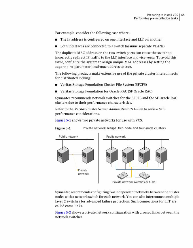
For example, consider the following case where:
■ The IP address is configured on one interface and LLT on another
■ Both interfaces are connected to a switch (assume separate VLANs)
The duplicate MAC address on the two switch ports can cause the switch toincorrectly redirect IP traffic to the LLT interface and vice versa. To avoid thisissue, configure the system to assign unique MAC addresses by setting theeeprom(1M) parameter local-mac-address to true.
The following products make extensive use of the private cluster interconnectsfor distributed locking:
■ Veritas Storage Foundation Cluster File System (SFCFS)
■ Veritas Storage Foundation for Oracle RAC (SF Oracle RAC)
Symantec recommends network switches for the SFCFS and the SF Oracle RACclusters due to their performance characteristics.
Refer to the Veritas Cluster Server Administrator's Guide to review VCSperformance considerations.
Figure 5-1 shows two private networks for use with VCS.
Figure 5-1 Private network setups: two-node and four-node clusters
Public network Public network
Privatenetwork
Private network switches or hubs
Symantec recommends configuring two independent networks between the clusternodes with a network switch for each network. You can also interconnect multiplelayer 2 switches for advanced failure protection. Such connections for LLT arecalled cross-links.
Figure 5-2 shows a private network configuration with crossed links between thenetwork switches.
65Preparing to install VCSPerforming preinstallation tasks
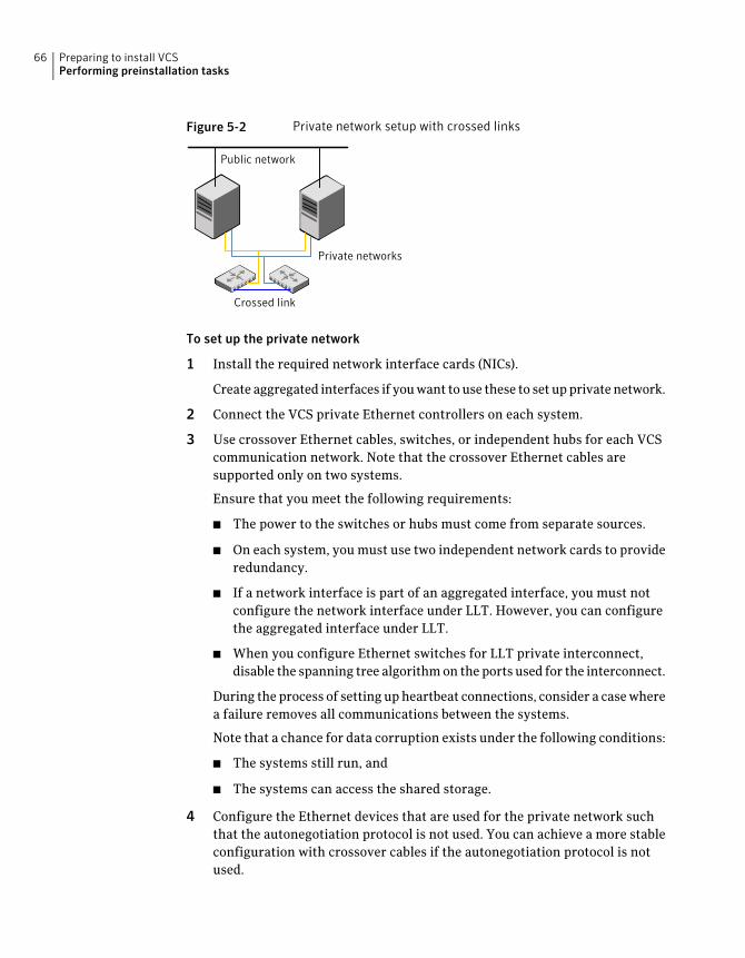
Figure 5-2 Private network setup with crossed links
Crossed link
Public network
Private networks
To set up the private network
1 Install the required network interface cards (NICs).
Create aggregated interfaces if you want to use these to set up private network.
2 Connect the VCS private Ethernet controllers on each system.
3 Use crossover Ethernet cables, switches, or independent hubs for each VCScommunication network. Note that the crossover Ethernet cables aresupported only on two systems.
Ensure that you meet the following requirements:
■ The power to the switches or hubs must come from separate sources.
■ On each system, you must use two independent network cards to provideredundancy.
■ If a network interface is part of an aggregated interface, you must notconfigure the network interface under LLT. However, you can configurethe aggregated interface under LLT.
■ When you configure Ethernet switches for LLT private interconnect,disable the spanning tree algorithm on the ports used for the interconnect.
During the process of setting up heartbeat connections, consider a case wherea failure removes all communications between the systems.
Note that a chance for data corruption exists under the following conditions:
■ The systems still run, and
■ The systems can access the shared storage.
4 Configure the Ethernet devices that are used for the private network suchthat the autonegotiation protocol is not used. You can achieve a more stableconfiguration with crossover cables if the autonegotiation protocol is notused.
Preparing to install VCSPerforming preinstallation tasks
66
To achieve this stable configuration, do one of the following:
■ Edit the /etc/system file to disable autonegotiation on all Ethernet devicessystem-wide.
■ Create a qfe.conf or bge.conf file in the /kernel/drv directory to disableautonegotiation for the individual devices that are used for privatenetwork.
Refer to the Oracle Ethernet driver product documentation for informationon these methods.
5 Test the network connections. Temporarily assign network addresses anduse telnet or ping to verify communications.
LLT uses its own protocol, and does not use TCP/IP. So, you must ensure thatthe private network connections are used only for LLT communication andnot for TCP/IP traffic. To verify this requirement, unplumb and unconfigureany temporary IP addresses that are configured on the network interfaces.
The installer configures the private network in the cluster duringconfiguration.
You can also manually configure LLT.
See “Configuring LLT manually” on page 253.
About using ssh or rsh with the Veritas installerThe installer uses passwordless secure shell (ssh) or remote shell (rsh)communications among systems. The installer uses the ssh or rsh daemon thatcomes bundled with the operating system. During an installation, you choose thecommunication method that you want to use. You then provide the installer withthe superuser passwords for the systems where you plan to install. The ssh or rshcommunication among the systems is removed when the installation processcompletes, unless the installation abruptly terminates. If installation terminatedabruptly, use the installation script's -comcleanup option to remove the ssh orrsh configuration from the systems.
See “Installation script options” on page 453.
In most installation, configuration, upgrade (where necessary), and uninstallationscenarios, the installer can configure ssh or rsh on the target systems. In thefollowing scenarios, you need to set up ssh or rsh manually:
■ When you perform installer sessions using a response file.
See “Setting up inter-system communication” on page 525.
67Preparing to install VCSPerforming preinstallation tasks
Setting up shared storageThe following sections describe how to set up the SCSI and the Fibre Channeldevices that the cluster systems share.
For I/O fencing, the data disks must support SCSI-3 persistent reservations. Youneed to configure a coordinator disk group that supports SCSI-3 PR and verifythat it works.
See “About planning to configure I/O fencing” on page 95.
See also the Veritas Cluster Server Administrator's Guide for a description of I/Ofencing.
Setting up shared storage: SCSI disksWhen SCSI devices are used for shared storage, the SCSI address or SCSI initiatorID of each node must be unique. Since each node typically has the default SCSIaddress of "7," the addresses of one or more nodes must be changed to avoid aconflict. In the following example, two nodes share SCSI devices. The SCSI addressof one node is changed to "5" by using nvedit commands to edit the nvramrc
script.
If you have more than two systems that share the SCSI bus, do the following:
■ Use the same procedure to set up shared storage.
■ Make sure to meet the following requirements:
■ The storage devices have power before any of the systems
■ Only one node runs at one time until each node's address is set to a uniquevalue
To set up shared storage
1 Install the required SCSI host adapters on each node that connects to thestorage, and make cable connections to the storage.
Refer to the documentation that is shipped with the host adapters, the storage,and the systems.
2 With both nodes powered off, power on the storage devices.
3 Power on one system, but do not allow it to boot. If necessary, halt the systemso that you can use the ok prompt.
Note that only one system must run at a time to avoid address conflicts.
Preparing to install VCSPerforming preinstallation tasks
68
4 Find the paths to the host adapters:
{0} ok show-disks
...b) /sbus@6,0/QLGC,isp@2,10000/sd
The example output shows the path to one host adapter. You must includethe path information without the "/sd" directory, in the nvramrc script. Thepath information varies from system to system.
5 Edit the nvramrc script on to change the scsi-initiator-id to 5. (The SolarisOpenBoot 3.x Command Reference Manual contains a full list of nveditcommands and keystrokes.) For example:
{0} ok nvedit
As you edit the script, note the following points:
■ Each line is numbered, 0:, 1:, 2:, and so on, as you enter the nvedit
commands.
■ On the line where the scsi-initiator-id is set, insert exactly one space afterthe first quotation mark and before scsi-initiator-id.
In this example, edit the nvramrc script as follows:
0: probe-all
1: cd /sbus@6,0/QLGC,isp@2,10000
2: 5 " scsi-initiator-id" integer-property
3: device-end
4: install-console
5: banner
6: <CTRL-C>
69Preparing to install VCSPerforming preinstallation tasks

6 Store the changes you make to the nvramrc script. The changes you make aretemporary until you store them.
{0} ok nvstore
If you are not sure of the changes you made, you can re-edit the script withoutrisk before you store it. You can display the contents of the nvramrc scriptby entering:
{0} ok printenv nvramrc
You can re-edit the file to make corrections:
{0} ok nvedit
Or, discard the changes if necessary by entering:
{0} ok nvquit
7 Instruct the OpenBoot PROM Monitor to use the nvramrc script on the node.
{0} ok setenv use-nvramrc? true
8 Reboot the node. If necessary, halt the system so that you can use the okprompt.
Preparing to install VCSPerforming preinstallation tasks
70
9 Verify that the scsi-initiator-id has changed. Go to the ok prompt. Use theoutput of the show-disks command to find the paths for the host adapters.Then, display the properties for the paths. For example:
{0} ok show-disks
...b) /sbus@6,0/QLGC,isp@2,10000/sd
{0} ok cd /sbus@6,0/QLGC,isp@2,10000
{0} ok .properties
scsi-initiator-id 00000005
Permit the system to continue booting.
10 Boot the second node. If necessary, halt the system to use the ok prompt.Verify that the scsi-initiator-id is 7. Use the output of the show-disks
command to find the paths for the host adapters. Then, display the propertiesfor that paths. For example:
{0} ok show-disks
...b) /sbus@6,0/QLGC,isp@2,10000/sd
{0} ok cd /sbus@6,0/QLGC,isp@2,10000
{0} ok .properties
scsi-initiator-id 00000007
Permit the system to continue booting.
Setting up shared storage: Fibre ChannelPerform the following steps to set up Fibre Channel.
To set up shared storage
1 Install the required FC-AL controllers.
2 Connect the FC-AL controllers and the shared storage devices to the samehub or switch.
All systems must see all the shared devices that are required to run the criticalapplication. If you want to implement zoning for a fibre switch, make surethat no zoning prevents all systems from seeing all these shared devices.
3 Boot each system with the reconfigure devices option:
ok boot -r
4 After all systems have booted, use the format(1m) command to verify thateach system can see all shared devices.
If Volume Manager is used, the same number of external disk devices mustappear, but device names (c#t#d#s#) may differ.
71Preparing to install VCSPerforming preinstallation tasks
If Volume Manager is not used, then you must meet the followingrequirements:
■ The same number of external disk devices must appear.
■ The device names must be identical for all devices on all systems.
Creating root userOn Oracle Solaris 11, you need to change the root role into a user as you cannotdirectly log in as root user.
To change root role into a user
1 Log in as local user and assume the root role.
% su - root
2 Remove the root role from local users who have been assigned the role.
# roles admin
root
# usermod -R " " admin
3 Change the root role into a user.
# rolemod -K type=normal root
4 Verify the change.
■ # getent user_attr root
root::::auths=solaris.*;profiles=All;audit_flags=lo\
:no;lock_after_retries=no;min_label=admin_low;clearance=admin_high
If the type keyword is missing in the output or is equal to normal, theaccount is not a role.
■ # userattr type root
If the output is empty or lists normal, the account is not a role.
Note: For more information, see the Oracle documentation on Oracle Solaris11 operating system.
Preparing to install VCSPerforming preinstallation tasks
72
Note: After installation, you may want to change root user into root role to allowlocal users to assume the root role.
See “Changing root user into root role” on page 365.
Setting the PATH variableInstallation commands as well as other commands reside in the /opt/VRTS/bindirectory. Add this directory to your PATH environment variable.
If you have any custom scripts located in /opt/VRTSvcs/bin directory, make sureto add the /opt/VRTSvcs/bin directory to your PATH environment variable.
To set the PATH variable
◆ Do one of the following:
■ For the Bourne Shell (sh), Bourne-again Shell (bash), or Korn shell (ksh),type:
# PATH=/opt/VRTS/bin:$PATH; export PATH
■ For the C Shell (csh) or enhanced C Shell (tcsh), type:
$ setenv PATH :/opt/VRTS/bin:$PATH
Setting the MANPATH variableSet the MANPATH variable to view the manual pages.
To set the MANPATH variable
◆ Do one of the following:
■ For the Bourne Shell (sh), Bourne-again Shell (bash), or Korn shell (ksh),type:
# MANPATH=/opt/VRTS/man:$MANPATH; export MANPATH
■ For the C Shell (csh) or enhanced C Shell (tcsh), type:
% setenv MANPATH /usr/share/man:/opt/VRTS/man
Disabling the abort sequence on SPARC systemsMost UNIX operating systems provide a method to perform a "break" or "consoleabort." The inherent problem when you abort a hung system is that it ceases to
73Preparing to install VCSPerforming preinstallation tasks
heartbeat in the cluster. When other cluster members believe that the abortednode is a failed node, these cluster members may begin corrective action.
Keep the following points in mind:
■ The only action that you must perform following a system abort is to reset thesystem to achieve the following:
■ Preserve data integrity
■ Prevent the cluster from taking additional corrective actions
■ Do not resume the processor as cluster membership may have changed andfailover actions may already be in progress.
■ To remove this potential problem on SPARC systems, you should alias the go
function in the OpenBoot eeprom to display a message.
To alias the go function to display a message
1 At the ok prompt, enter:
nvedit
2 Press Ctrl+L to display the current contents of the nvramrc buffer.
3 Press Ctrl+N until the editor displays the last line of the buffer.
4 Add the following lines exactly as shown. Press Enter after adding each line.
." Aliasing the OpenBoot 'go' command! "
: go ." It is inadvisable to use the 'go' command in a clustered
environment. " cr
." Please use the 'power-off' or 'reset-all' commands instead. "
cr
." Thank you, from your friendly neighborhood sysadmin. " ;
5 Press Ctrl+C to exit the nvramrc editor.
6 To verify that no errors exist, type the nvrun command. You should see onlythe following text:
Aliasing the OpenBoot 'go' command!
7 Type the nvstore command to commit your changes to the non-volatile RAM(NVRAM) for use in subsequent reboots.
8 After you perform these commands, at reboot you see this output:
Aliasing the OpenBoot 'go' command! go isn't unique.
Preparing to install VCSPerforming preinstallation tasks
74
Optimizing LLT media speed settings on private NICsFor optimal LLT communication among the cluster nodes, the interface cards oneach node must use the same media speed settings. Also, the settings for theswitches or the hubs that are used for the LLT interconnections must match thatof the interface cards. Incorrect settings can cause poor network performance oreven network failure.
If you use different media speed for the private NICs, Symantec recommends thatyou configure the NICs with lesser speed as low-priority links to enhance LLTperformance.
Guidelines for setting the media speed of the LLT interconnectsReview the following guidelines for setting the media speed of the LLTinterconnects:
■ Symantec recommends that you manually set the same media speed settingon each Ethernet card on each node.If you use different media speed for the private NICs, Symantec recommendsthat you configure the NICs with lesser speed as low-priority links to enhanceLLT performance.
■ If you have hubs or switches for LLT interconnects, then set the hub or switchport to the same setting as used on the cards on each node.
■ If you use directly connected Ethernet links (using crossover cables), Symantecrecommends that you set the media speed to the highest value common toboth cards, typically 1000_Full_Duplex.
Details for setting the media speeds for specific devices are outside of the scopeof this manual. Consult the device’s documentation or the operating system manualfor more information.
Preparing zone environmentsYou need to keep the following items in mind when you install or upgrade VCS ina zone environment on an Oracle Solaris 10 operating system.
■ When you install or upgrade VCS using the installer program, all zones areupgraded (both global and non-global) unless they are detached and unmounted.
■ Make sure that all non-global zones are booted and in the running state beforeyou install or upgrade the VCS packages in the global zone. If the non-globalzones are not mounted and running at the time of upgrade, you must upgradeeach package in each non-global zone manually.
75Preparing to install VCSPerforming preinstallation tasks
■ If you install VCS on Solaris 10 systems that run non-global zones, you needto make sure that non-global zones do not inherit the /opt directory. Run thefollowing command to make sure that the /opt directory is not in theinherit-pkg-dir clause:
# zonecfg -z zone_name info
zonepath: /export/home/zone1
autoboot: false
pool: yourpool
inherit-pkg-dir:
dir: /lib
inherit-pkg-dir:
dir: /platform
inherit-pkg-dir:
dir: /sbin
inherit-pkg-dir:
dir: /usr
If the /opt directory appears in the output, remove the /opt directory from thezone's configuration and reinstall the zone.
With Oracle Solaris 11, after installing packages in the global zone, you need toinstall the required packages in the non-global zone.
Mounting the product discYou must have superuser (root) privileges to load the VCS software.
To mount the product disc
1 Log in as superuser on a system where you want to install VCS.
The system from which you install VCS need not be part of the cluster. Thesystems must be in the same subnet.
2 Insert the product disc into a DVD drive that is connected to your system.
3 If Solaris volume management software is running on your system, thesoftware disc automatically mounts as /cdrom/cdrom0.
4 If Solaris volume management software is not available to mount the DVD,you must mount it manually. After you insert the software disc, enter:
# mount -F hsfs -o ro /dev/dsk/c0t6d0s2 /cdrom
Where c0t6d0s2 is the default address for the disc drive.
Preparing to install VCSPerforming preinstallation tasks
76
Performing automated preinstallation checkBefore you begin the installation of VCS software, you can check the readiness ofthe systems where you plan to install VCS. The command to start thepreinstallation check is:
installvcs -precheck system1 system2 ...
You can also run the installer -precheck command.
See “About Symantec Operations Readiness Tools” on page 30.
You can use the Veritas Operation Services to assess your setup for VCSinstallation.
To check the systems
1 Navigate to the folder that contains the installvcs program.
# cd /cdrom/cdrom0/cluster_server
2 Start the preinstallation check:
# ./installvcs -precheck sys1 sys2
The program proceeds in a noninteractive mode to examine the systems forlicenses, packages, disk space, and system-to-system communications.
3 Review the output as the program displays the results of the check and savesthe results of the check in a log file.
Reformatting VCS configuration files on a stopped clusterWhen you manually edit VCS configuration files (for example, the main.cf ortypes.cf file) you can potentially create formatting issues that may cause theinstaller to interpret the cluster configuration information incorrectly.
If you have manually edited any of the configuration files, you need to performone of the following before you run the installation program:
■ On a running cluster, perform an haconf -dump command. This commandsaves the configuration files and ensures that they do not have formattingerrors before you run the installer.
■ On cluster that is not running, perform the hacf -cftocmd and then the hacf-cmdtocf commands to format the configuration files.
77Preparing to install VCSPerforming preinstallation tasks
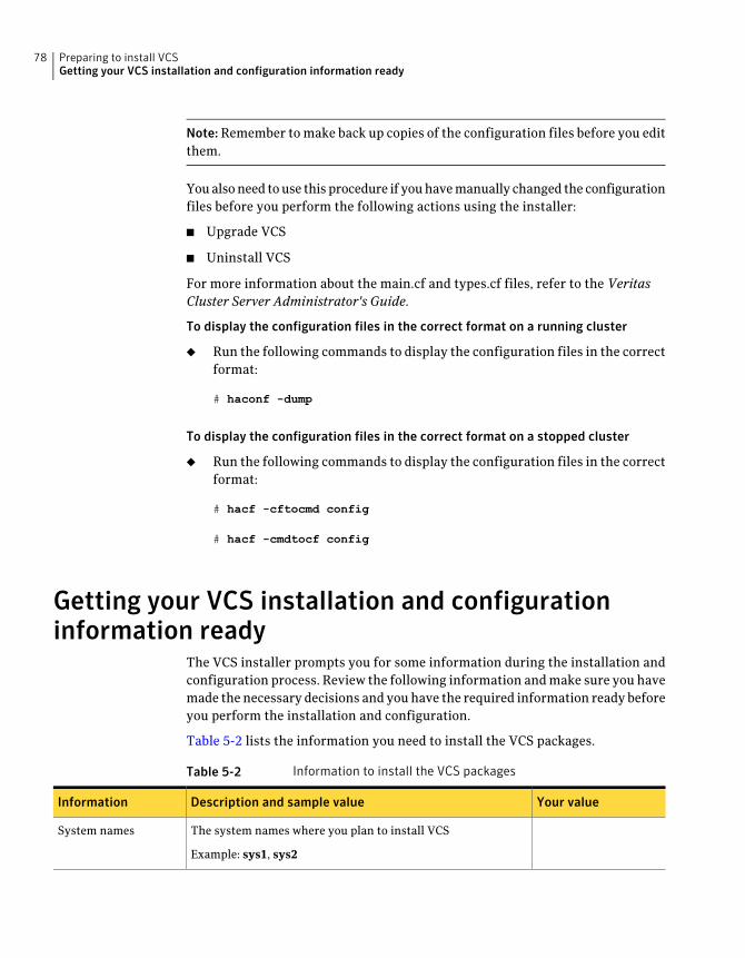
Note:Remember to make back up copies of the configuration files before you editthem.
You also need to use this procedure if you have manually changed the configurationfiles before you perform the following actions using the installer:
■ Upgrade VCS
■ Uninstall VCS
For more information about the main.cf and types.cf files, refer to the VeritasCluster Server Administrator's Guide.
To display the configuration files in the correct format on a running cluster
◆ Run the following commands to display the configuration files in the correctformat:
# haconf -dump
To display the configuration files in the correct format on a stopped cluster
◆ Run the following commands to display the configuration files in the correctformat:
# hacf -cftocmd config
# hacf -cmdtocf config
Getting your VCS installation and configurationinformation ready
The VCS installer prompts you for some information during the installation andconfiguration process. Review the following information and make sure you havemade the necessary decisions and you have the required information ready beforeyou perform the installation and configuration.
Table 5-2 lists the information you need to install the VCS packages.
Table 5-2 Information to install the VCS packages
Your valueDescription and sample valueInformation
The system names where you plan to install VCS
Example: sys1, sys2
System names
Preparing to install VCSGetting your VCS installation and configuration information ready
78
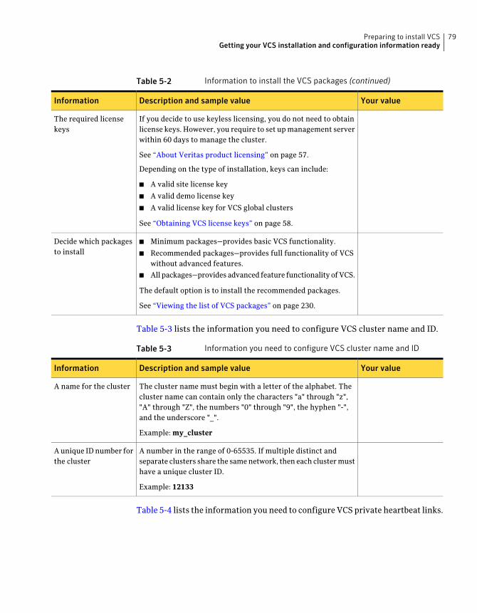
Table 5-2 Information to install the VCS packages (continued)
Your valueDescription and sample valueInformation
If you decide to use keyless licensing, you do not need to obtainlicense keys. However, you require to set up management serverwithin 60 days to manage the cluster.
See “About Veritas product licensing” on page 57.
Depending on the type of installation, keys can include:
■ A valid site license key
■ A valid demo license key
■ A valid license key for VCS global clusters
See “Obtaining VCS license keys” on page 58.
The required licensekeys
■ Minimum packages—provides basic VCS functionality.
■ Recommended packages—provides full functionality of VCSwithout advanced features.
■ All packages—provides advanced feature functionality of VCS.
The default option is to install the recommended packages.
See “Viewing the list of VCS packages” on page 230.
Decide which packagesto install
Table 5-3 lists the information you need to configure VCS cluster name and ID.
Table 5-3 Information you need to configure VCS cluster name and ID
Your valueDescription and sample valueInformation
The cluster name must begin with a letter of the alphabet. Thecluster name can contain only the characters "a" through "z","A" through "Z", the numbers "0" through "9", the hyphen "-",and the underscore "_".
Example: my_cluster
A name for the cluster
A number in the range of 0-65535. If multiple distinct andseparate clusters share the same network, then each cluster musthave a unique cluster ID.
Example: 12133
A unique ID number forthe cluster
Table 5-4 lists the information you need to configure VCS private heartbeat links.
79Preparing to install VCSGetting your VCS installation and configuration information ready
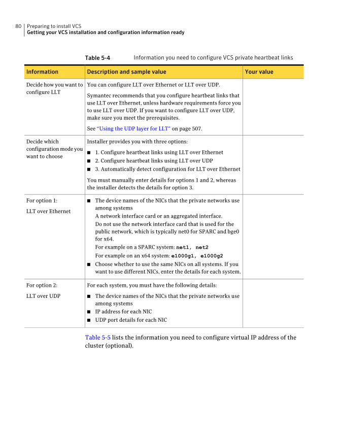
Table 5-4 Information you need to configure VCS private heartbeat links
Your valueDescription and sample valueInformation
You can configure LLT over Ethernet or LLT over UDP.
Symantec recommends that you configure heartbeat links thatuse LLT over Ethernet, unless hardware requirements force youto use LLT over UDP. If you want to configure LLT over UDP,make sure you meet the prerequisites.
See “Using the UDP layer for LLT” on page 507.
Decide how you want toconfigure LLT
Installer provides you with three options:
■ 1. Configure heartbeat links using LLT over Ethernet
■ 2. Configure heartbeat links using LLT over UDP
■ 3. Automatically detect configuration for LLT over Ethernet
You must manually enter details for options 1 and 2, whereasthe installer detects the details for option 3.
Decide whichconfiguration mode youwant to choose
■ The device names of the NICs that the private networks useamong systems
A network interface card or an aggregated interface.
Do not use the network interface card that is used for thepublic network, which is typically net0 for SPARC and bge0for x64.
For example on a SPARC system: net1, net2
For example on an x64 system: e1000g1, e1000g2
■ Choose whether to use the same NICs on all systems. If youwant to use different NICs, enter the details for each system.
For option 1:
LLT over Ethernet
For each system, you must have the following details:
■ The device names of the NICs that the private networks useamong systems
■ IP address for each NIC
■ UDP port details for each NIC
For option 2:
LLT over UDP
Table 5-5 lists the information you need to configure virtual IP address of thecluster (optional).
Preparing to install VCSGetting your VCS installation and configuration information ready
80
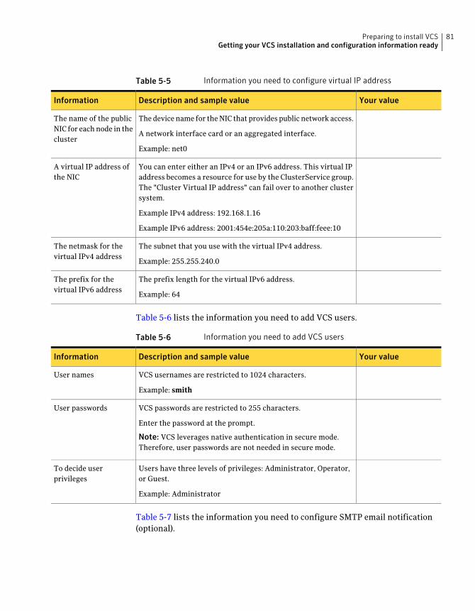
Table 5-5 Information you need to configure virtual IP address
Your valueDescription and sample valueInformation
The device name for the NIC that provides public network access.
A network interface card or an aggregated interface.
Example: net0
The name of the publicNIC for each node in thecluster
You can enter either an IPv4 or an IPv6 address. This virtual IPaddress becomes a resource for use by the ClusterService group.The "Cluster Virtual IP address" can fail over to another clustersystem.
Example IPv4 address: 192.168.1.16
Example IPv6 address: 2001:454e:205a:110:203:baff:feee:10
A virtual IP address ofthe NIC
The subnet that you use with the virtual IPv4 address.
Example: 255.255.240.0
The netmask for thevirtual IPv4 address
The prefix length for the virtual IPv6 address.
Example: 64
The prefix for thevirtual IPv6 address
Table 5-6 lists the information you need to add VCS users.
Table 5-6 Information you need to add VCS users
Your valueDescription and sample valueInformation
VCS usernames are restricted to 1024 characters.
Example: smith
User names
VCS passwords are restricted to 255 characters.
Enter the password at the prompt.
Note: VCS leverages native authentication in secure mode.Therefore, user passwords are not needed in secure mode.
User passwords
Users have three levels of privileges: Administrator, Operator,or Guest.
Example: Administrator
To decide userprivileges
Table 5-7 lists the information you need to configure SMTP email notification(optional).
81Preparing to install VCSGetting your VCS installation and configuration information ready
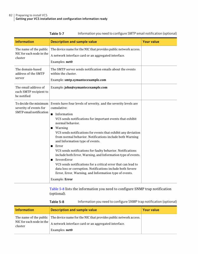
Table 5-7 Information you need to configure SMTP email notification (optional)
Your valueDescription and sample valueInformation
The device name for the NIC that provides public network access.
A network interface card or an aggregated interface.
Examples: net0
The name of the publicNIC for each node in thecluster
The SMTP server sends notification emails about the eventswithin the cluster.
Example: smtp.symantecexample.com
The domain-basedaddress of the SMTPserver
Example: [email protected] email address ofeach SMTP recipient tobe notified
Events have four levels of severity, and the severity levels arecumulative:
■ Information
VCS sends notifications for important events that exhibitnormal behavior.
■ Warning
VCS sends notifications for events that exhibit any deviationfrom normal behavior. Notifications include both Warningand Information type of events.
■ Error
VCS sends notifications for faulty behavior. Notificationsinclude both Error, Warning, and Information type of events.
■ SevereError
VCS sends notifications for a critical error that can lead todata loss or corruption. Notifications include both SevereError, Error, Warning, and Information type of events.
Example: Error
To decide the minimumseverity of events forSMTP email notification
Table 5-8 lists the information you need to configure SNMP trap notification(optional).
Table 5-8 Information you need to configure SNMP trap notification (optional)
Your valueDescription and sample valueInformation
The device name for the NIC that provides public network access.
A network interface card or an aggregated interface.
Examples: net0
The name of the publicNIC for each node in thecluster
Preparing to install VCSGetting your VCS installation and configuration information ready
82
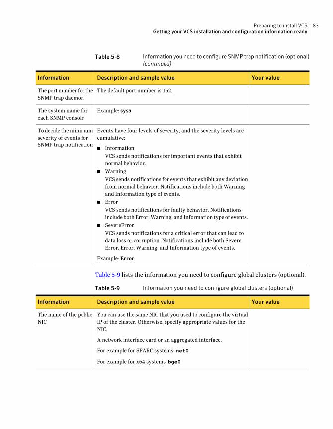
Table 5-8 Information you need to configure SNMP trap notification (optional)(continued)
Your valueDescription and sample valueInformation
The default port number is 162.The port number for theSNMP trap daemon
Example: sys5The system name foreach SNMP console
Events have four levels of severity, and the severity levels arecumulative:
■ Information
VCS sends notifications for important events that exhibitnormal behavior.
■ Warning
VCS sends notifications for events that exhibit any deviationfrom normal behavior. Notifications include both Warningand Information type of events.
■ Error
VCS sends notifications for faulty behavior. Notificationsinclude both Error, Warning, and Information type of events.
■ SevereError
VCS sends notifications for a critical error that can lead todata loss or corruption. Notifications include both SevereError, Error, Warning, and Information type of events.
Example: Error
To decide the minimumseverity of events forSNMP trap notification
Table 5-9 lists the information you need to configure global clusters (optional).
Table 5-9 Information you need to configure global clusters (optional)
Your valueDescription and sample valueInformation
You can use the same NIC that you used to configure the virtualIP of the cluster. Otherwise, specify appropriate values for theNIC.
A network interface card or an aggregated interface.
For example for SPARC systems: net0
For example for x64 systems: bge0
The name of the publicNIC
83Preparing to install VCSGetting your VCS installation and configuration information ready
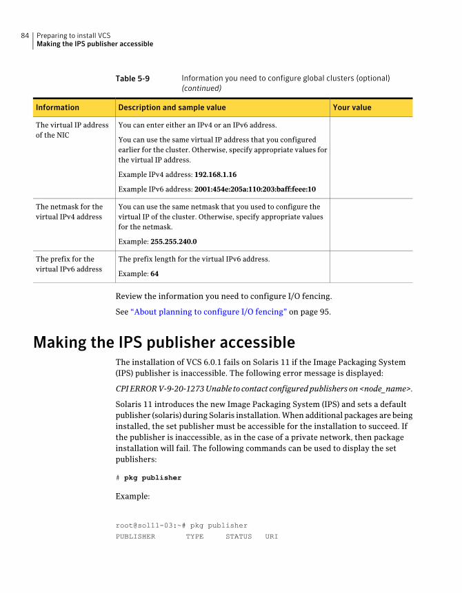
Table 5-9 Information you need to configure global clusters (optional)(continued)
Your valueDescription and sample valueInformation
You can enter either an IPv4 or an IPv6 address.
You can use the same virtual IP address that you configuredearlier for the cluster. Otherwise, specify appropriate values forthe virtual IP address.
Example IPv4 address: 192.168.1.16
Example IPv6 address: 2001:454e:205a:110:203:baff:feee:10
The virtual IP addressof the NIC
You can use the same netmask that you used to configure thevirtual IP of the cluster. Otherwise, specify appropriate valuesfor the netmask.
Example: 255.255.240.0
The netmask for thevirtual IPv4 address
The prefix length for the virtual IPv6 address.
Example: 64
The prefix for thevirtual IPv6 address
Review the information you need to configure I/O fencing.
See “About planning to configure I/O fencing” on page 95.
Making the IPS publisher accessibleThe installation of VCS 6.0.1 fails on Solaris 11 if the Image Packaging System(IPS) publisher is inaccessible. The following error message is displayed:
CPIERRORV-9-20-1273Unable to contact configuredpublishers on<node_name>.
Solaris 11 introduces the new Image Packaging System (IPS) and sets a defaultpublisher (solaris) during Solaris installation. When additional packages are beinginstalled, the set publisher must be accessible for the installation to succeed. Ifthe publisher is inaccessible, as in the case of a private network, then packageinstallation will fail. The following commands can be used to display the setpublishers:
# pkg publisher
Example:
root@sol11-03:~# pkg publisher
PUBLISHER TYPE STATUS URI
Preparing to install VCSMaking the IPS publisher accessible
84
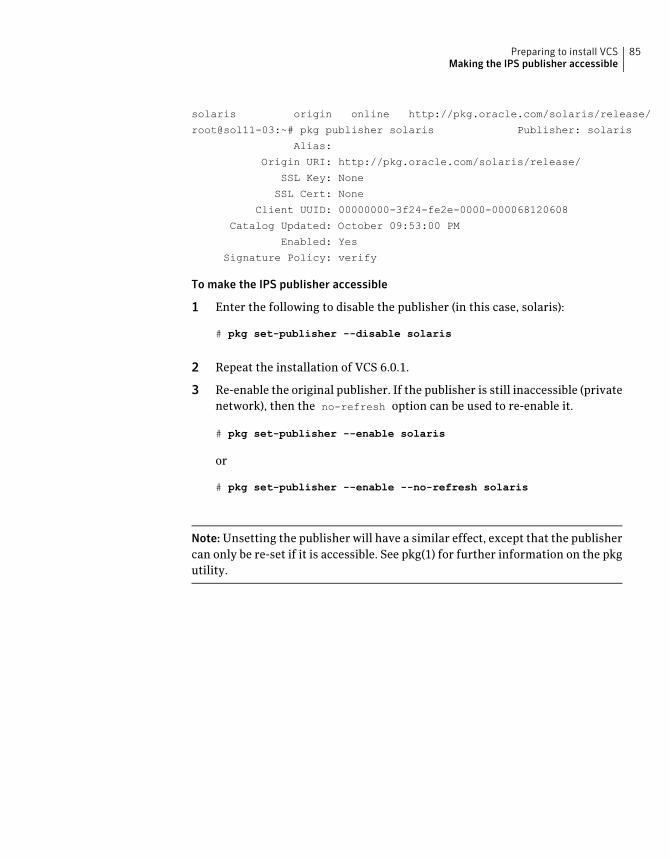
solaris origin online http://pkg.oracle.com/solaris/release/
root@sol11-03:~# pkg publisher solaris Publisher: solaris
Alias:
Origin URI: http://pkg.oracle.com/solaris/release/
SSL Key: None
SSL Cert: None
Client UUID: 00000000-3f24-fe2e-0000-000068120608
Catalog Updated: October 09:53:00 PM
Enabled: Yes
Signature Policy: verify
To make the IPS publisher accessible
1 Enter the following to disable the publisher (in this case, solaris):
# pkg set-publisher --disable solaris
2 Repeat the installation of VCS 6.0.1.
3 Re-enable the original publisher. If the publisher is still inaccessible (privatenetwork), then the no-refresh option can be used to re-enable it.
# pkg set-publisher --enable solaris
or
# pkg set-publisher --enable --no-refresh solaris
Note:Unsetting the publisher will have a similar effect, except that the publishercan only be re-set if it is accessible. See pkg(1) for further information on the pkgutility.
85Preparing to install VCSMaking the IPS publisher accessible

Preparing to install VCSMaking the IPS publisher accessible
86
Installation using thescript-based installer
■ Chapter 6. Installing VCS
■ Chapter 7. Preparing to configure VCS clusters for data integrity
■ Chapter 8. Configuring VCS
■ Chapter 9. Configuring VCS clusters for data integrity
3Section

88
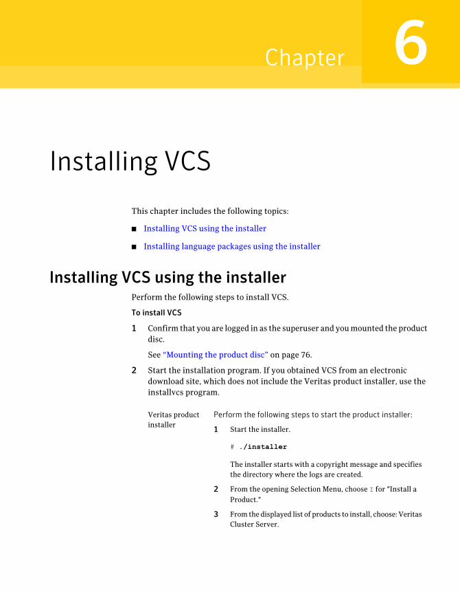
Installing VCS
This chapter includes the following topics:
■ Installing VCS using the installer
■ Installing language packages using the installer
Installing VCS using the installerPerform the following steps to install VCS.
To install VCS
1 Confirm that you are logged in as the superuser and you mounted the productdisc.
See “Mounting the product disc” on page 76.
2 Start the installation program. If you obtained VCS from an electronicdownload site, which does not include the Veritas product installer, use theinstallvcs program.
Perform the following steps to start the product installer:
1 Start the installer.
# ./installer
The installer starts with a copyright message and specifiesthe directory where the logs are created.
2 From the opening Selection Menu, choose I for "Install aProduct."
3 From the displayed list of products to install, choose: VeritasCluster Server.
Veritas productinstaller
6Chapter
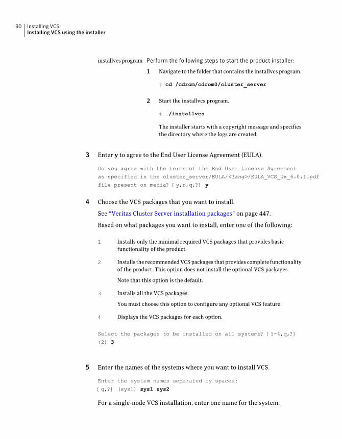
Perform the following steps to start the product installer:
1 Navigate to the folder that contains the installvcs program.
# cd /cdrom/cdrom0/cluster_server
2 Start the installvcs program.
# ./installvcs
The installer starts with a copyright message and specifiesthe directory where the logs are created.
installvcs program
3 Enter y to agree to the End User License Agreement (EULA).
Do you agree with the terms of the End User License Agreement
as specified in the cluster_server/EULA/<lang>/EULA_VCS_Ux_6.0.1.pdf
file present on media? [y,n,q,?] y
4 Choose the VCS packages that you want to install.
See “Veritas Cluster Server installation packages” on page 447.
Based on what packages you want to install, enter one of the following:
Installs only the minimal required VCS packages that provides basicfunctionality of the product.
1
Installs the recommended VCS packages that provides complete functionalityof the product. This option does not install the optional VCS packages.
Note that this option is the default.
2
Installs all the VCS packages.
You must choose this option to configure any optional VCS feature.
3
Displays the VCS packages for each option.4
Select the packages to be installed on all systems? [1-4,q,?]
(2) 3
5 Enter the names of the systems where you want to install VCS.
Enter the system names separated by spaces:
[q,?] (sys1) sys1 sys2
For a single-node VCS installation, enter one name for the system.
Installing VCSInstalling VCS using the installer
90
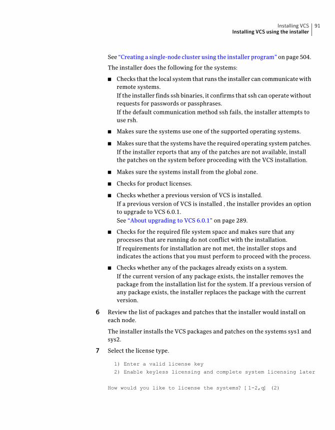
See “Creating a single-node cluster using the installer program” on page 504.
The installer does the following for the systems:
■ Checks that the local system that runs the installer can communicate withremote systems.If the installer finds ssh binaries, it confirms that ssh can operate withoutrequests for passwords or passphrases.If the default communication method ssh fails, the installer attempts touse rsh.
■ Makes sure the systems use one of the supported operating systems.
■ Makes sure that the systems have the required operating system patches.If the installer reports that any of the patches are not available, installthe patches on the system before proceeding with the VCS installation.
■ Makes sure the systems install from the global zone.
■ Checks for product licenses.
■ Checks whether a previous version of VCS is installed.If a previous version of VCS is installed , the installer provides an optionto upgrade to VCS 6.0.1.See “About upgrading to VCS 6.0.1” on page 289.
■ Checks for the required file system space and makes sure that anyprocesses that are running do not conflict with the installation.If requirements for installation are not met, the installer stops andindicates the actions that you must perform to proceed with the process.
■ Checks whether any of the packages already exists on a system.If the current version of any package exists, the installer removes thepackage from the installation list for the system. If a previous version ofany package exists, the installer replaces the package with the currentversion.
6 Review the list of packages and patches that the installer would install oneach node.
The installer installs the VCS packages and patches on the systems sys1 andsys2.
7 Select the license type.
1) Enter a valid license key
2) Enable keyless licensing and complete system licensing later
How would you like to license the systems? [1-2,q] (2)
91Installing VCSInstalling VCS using the installer

Based on what license type you want to use, enter one of the following:
You must have a valid license key. Enter the license key at the prompt:
Enter a VCS license key: [b,q,?]XXXX-XXXX-XXXX-XXXX-XXXX
If you plan to configure global clusters, enter the corresponding license keyswhen the installer prompts for additional licenses.
Do you wish to enter additional licenses? [y,n,q,b] (n) y
1
The keyless license option enables you to install VCS without entering a key.However, to ensure compliance, keyless licensing requires that you managethe systems with a management server.
For more information, go to the following website:
http://go.symantec.com/sfhakeyless
Note that this option is the default.
2
The installer registers the license and completes the installation process.
8 To install the Global Cluster Option, enter y at the prompt.
9 To configure VCS, enter y at the prompt. You can also configure VCS later.
Would you like to configure VCS on sys1 sys2 [y,n,q] (n) n
See “Overview of tasks to configure VCS using the script-based installer”on page 128.
10 Enter y at the prompt to send the installation information to Symantec.
Would you like to send the information about this installation
to Symantec to help improve installation in the future?
[y,n,q,?] (y) y
The installer provides an option to collect data about the installation processeach time you complete an installation, upgrade, configuration, or uninstallof the product. The installer transfers the contents of the install log files toan internal Symantec site. The information is used only to gather metricsabout how you use the installer. No personal customer data is collected, andno information will be shared by any other parties. Information gatheredmay include the product and the version installed or upgraded, how manysystems were installed, and the time spent in any section of the install process.
Installing VCSInstalling VCS using the installer
92
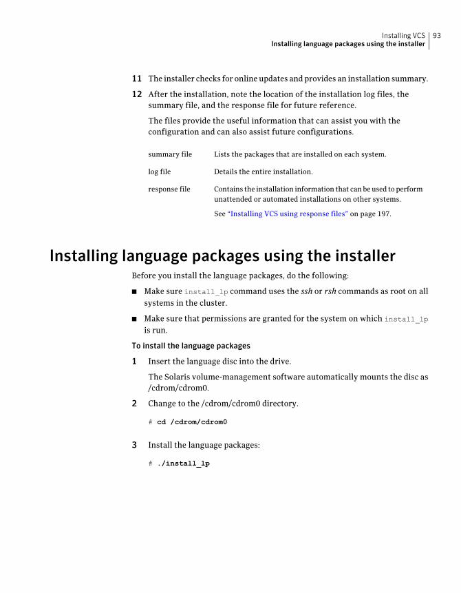
11 The installer checks for online updates and provides an installation summary.
12 After the installation, note the location of the installation log files, thesummary file, and the response file for future reference.
The files provide the useful information that can assist you with theconfiguration and can also assist future configurations.
Lists the packages that are installed on each system.summary file
Details the entire installation.log file
Contains the installation information that can be used to performunattended or automated installations on other systems.
See “Installing VCS using response files” on page 197.
response file
Installing language packages using the installerBefore you install the language packages, do the following:
■ Make sure install_lp command uses the ssh or rsh commands as root on allsystems in the cluster.
■ Make sure that permissions are granted for the system on which install_lp
is run.
To install the language packages
1 Insert the language disc into the drive.
The Solaris volume-management software automatically mounts the disc as/cdrom/cdrom0.
2 Change to the /cdrom/cdrom0 directory.
# cd /cdrom/cdrom0
3 Install the language packages:
# ./install_lp
93Installing VCSInstalling language packages using the installer

Installing VCSInstalling language packages using the installer
94
Preparing to configure VCSclusters for data integrity
This chapter includes the following topics:
■ About planning to configure I/O fencing
■ Setting up the CP server
About planning to configure I/O fencingAfter you configure VCS with the installer, you must configure I/O fencing in thecluster for data integrity.
You can configure disk-based I/O fencing or server-based I/O fencing. If yourenterprise setup has multiple clusters that use VCS for clustering, Symantecrecommends you to configure server-based I/O fencing.
The coordination points in server-based fencing can include only CP servers or amix of CP servers and coordinator disks. Symantec also supports server-basedfencing with a single coordination point which is a single highly available CPserver that is hosted on an SFHA cluster.
Warning: For server-based fencing configurations that use a single coordinationpoint (CP server), the coordination point becomes a single point of failure. In suchconfigurations, the arbitration facility is not available during a failover of the CPserver in the SFHA cluster. So, if a network partition occurs on any applicationcluster during the CP server failover, the application cluster is brought down.Symantec recommends the use of single CP server-based fencing only in testenvironments.
7Chapter

If you have installed VCS in a virtual environment that is not SCSI-3 PR compliant,you can configure non-SCSI-3 server-based fencing.
See Figure 7-2 on page 98.
Figure 7-1 illustrates a high-level flowchart to configure I/O fencing for the VCScluster.
Preparing to configure VCS clusters for data integrityAbout planning to configure I/O fencing
96
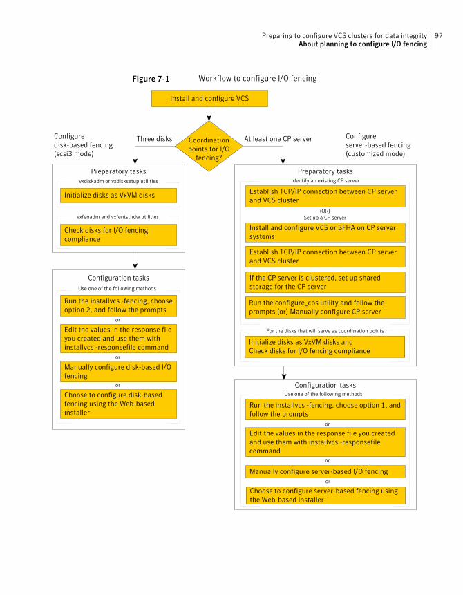
Figure 7-1 Workflow to configure I/O fencing
Initialize disks as VxVM disks
Check disks for I/O fencingcompliance
Manually configure disk-based I/Ofencing
Preparatory tasksvxdiskadm or vxdisksetup utilities
vxfenadm and vxfentsthdw utilities
Configuredisk-based fencing(scsi3 mode)
Configureserver-based fencing(customized mode)
Configuration tasksUse one of the following methods
Edit the values in the response fileyou created and use them withinstallvcs -responsefile command
Install and configure VCS or SFHA on CP serversystems
Establish TCP/IP connection between CP serverand VCS cluster
Edit the values in the response file you createdand use them with installvcs -responsefilecommand
Manually configure server-based I/O fencing
Preparatory tasksIdentify an existing CP server
Configuration tasksUse one of the following methods
Run the installvcs -fencing, choose option 1, andfollow the prompts
If the CP server is clustered, set up sharedstorage for the CP server
Run the configure_cps utility and follow theprompts (or) Manually configure CP server
Coordinationpoints for I/O
fencing?
Three disks At least one CP server
Initialize disks as VxVM disks andCheck disks for I/O fencing compliance
For the disks that will serve as coordination points
Install and configure VCS
Run the installvcs -fencing, chooseoption 2, and follow the prompts
(OR)Set up a CP server
Establish TCP/IP connection between CP serverand VCS cluster
or
or
or
or
Choose to configure disk-basedfencing using the Web-basedinstaller
or
Choose to configure server-based fencing usingthe Web-based installer
or
97Preparing to configure VCS clusters for data integrityAbout planning to configure I/O fencing
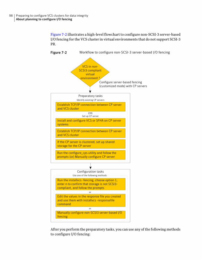
Figure 7-2 illustrates a high-level flowchart to configure non-SCSI-3 server-basedI/O fencing for the VCS cluster in virtual environments that do not support SCSI-3PR.
Figure 7-2 Workflow to configure non-SCSI-3 server-based I/O fencing
Configure server-based fencing(customized mode) with CP servers
Install and configure VCS or SFHA on CP serversystems
Establish TCP/IP connection between CP serverand VCS cluster
Edit the values in the response file you createdand use them with installvcs -responsefilecommand
Manually configure non-SCSI3 server-based I/Ofencing
Preparatory tasksIdentify existing CP servers
Configuration tasksUse one of the following methods
Run the installvcs -fencing, choose option 1,enter n to confirm that storage is not SCSI3-compliant, and follow the prompts
If the CP server is clustered, set up sharedstorage for the CP server
Run the configure_cps utility and follow theprompts (or) Manually configure CP server
VCS in non-SCSI3 compliant
virtualenvironment ?
(OR)Set up CP server
Establish TCP/IP connection between CP serverand VCS cluster
or
or
After you perform the preparatory tasks, you can use any of the following methodsto configure I/O fencing:
Preparing to configure VCS clusters for data integrityAbout planning to configure I/O fencing
98
See “Setting up disk-based I/O fencing using installvcs program” on page 151.
See “Setting up server-based I/O fencing using installvcs program” on page 159.
See “Setting up non-SCSI-3 server-based I/O fencing in virtual environments usinginstallvcs program” on page 168.
Using the installvcsprogram
See “Configuring VCS for data integrity using the Web-based installer” on page 186.Using the Web-basedinstaller
See “Response file variables to configure disk-based I/O fencing” on page 216.
See “Response file variables to configure server-based I/O fencing” on page 220.
See “Response file variables to configure non-SCSI-3 server-based I/O fencing” on page 222.
See “Configuring I/O fencing using response files” on page 215.
Using response files
See “Setting up disk-based I/O fencing manually” on page 263.
See “Setting up server-based I/O fencing manually” on page 268.
See “Setting up non-SCSI-3 fencing in virtual environments manually” on page 281.
Manually editingconfiguration files
You can also migrate from one I/O fencing configuration to another.
See the Veritas Storage foundation High Availability Administrator's Guide formore details.
Typical VCS cluster configuration with disk-based I/O fencingFigure 7-3 displays a typical VCS configuration with two nodes and shared storage.The configuration uses three coordinator disks for I/O fencing.
99Preparing to configure VCS clusters for data integrityAbout planning to configure I/O fencing
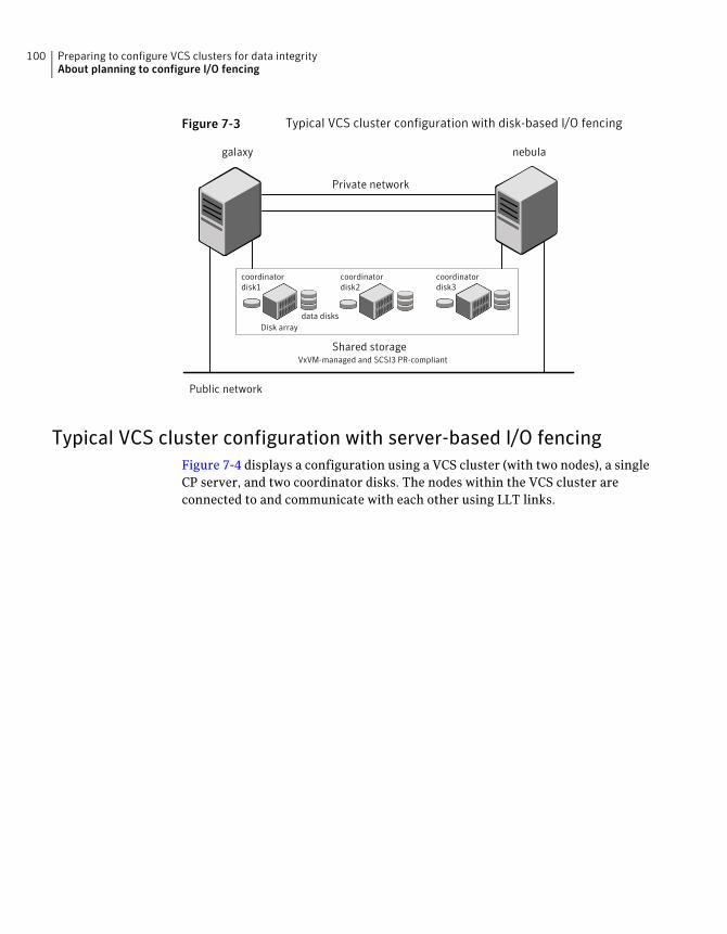
Figure 7-3 Typical VCS cluster configuration with disk-based I/O fencing
Public network
Private network
Shared storage
galaxy nebula
coordinatordisk1
data disksDisk array
coordinatordisk2
coordinatordisk3
VxVM-managed and SCSI3 PR-compliant
Typical VCS cluster configuration with server-based I/O fencingFigure 7-4 displays a configuration using a VCS cluster (with two nodes), a singleCP server, and two coordinator disks. The nodes within the VCS cluster areconnected to and communicate with each other using LLT links.
Preparing to configure VCS clusters for data integrityAbout planning to configure I/O fencing
100
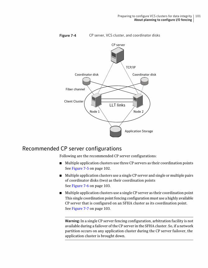
Figure 7-4 CP server, VCS cluster, and coordinator disks
Coordinator disk Coordinator disk
CP server
Client Cluster
Node 1 Node 2
Application Storage
LLT links
TCP/IP
Fiber channel
Recommended CP server configurationsFollowing are the recommended CP server configurations:
■ Multiple application clusters use three CP servers as their coordination pointsSee Figure 7-5 on page 102.
■ Multiple application clusters use a single CP server and single or multiple pairsof coordinator disks (two) as their coordination pointsSee Figure 7-6 on page 103.
■ Multiple application clusters use a single CP server as their coordination pointThis single coordination point fencing configuration must use a highly availableCP server that is configured on an SFHA cluster as its coordination point.See Figure 7-7 on page 103.
Warning: In a single CP server fencing configuration, arbitration facility is notavailable during a failover of the CP server in the SFHA cluster. So, if a networkpartition occurs on any application cluster during the CP server failover, theapplication cluster is brought down.
101Preparing to configure VCS clusters for data integrityAbout planning to configure I/O fencing
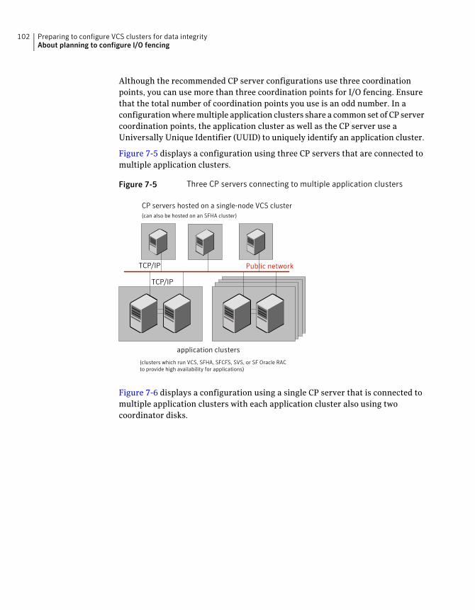
Although the recommended CP server configurations use three coordinationpoints, you can use more than three coordination points for I/O fencing. Ensurethat the total number of coordination points you use is an odd number. In aconfiguration where multiple application clusters share a common set of CP servercoordination points, the application cluster as well as the CP server use aUniversally Unique Identifier (UUID) to uniquely identify an application cluster.
Figure 7-5 displays a configuration using three CP servers that are connected tomultiple application clusters.
Figure 7-5 Three CP servers connecting to multiple application clusters
Public networkTCP/IP
TCP/IP
CP servers hosted on a single-node VCS cluster(can also be hosted on an SFHA cluster)
application clusters
(clusters which run VCS, SFHA, SFCFS, SVS, or SF Oracle RACto provide high availability for applications)
Figure 7-6 displays a configuration using a single CP server that is connected tomultiple application clusters with each application cluster also using twocoordinator disks.
Preparing to configure VCS clusters for data integrityAbout planning to configure I/O fencing
102
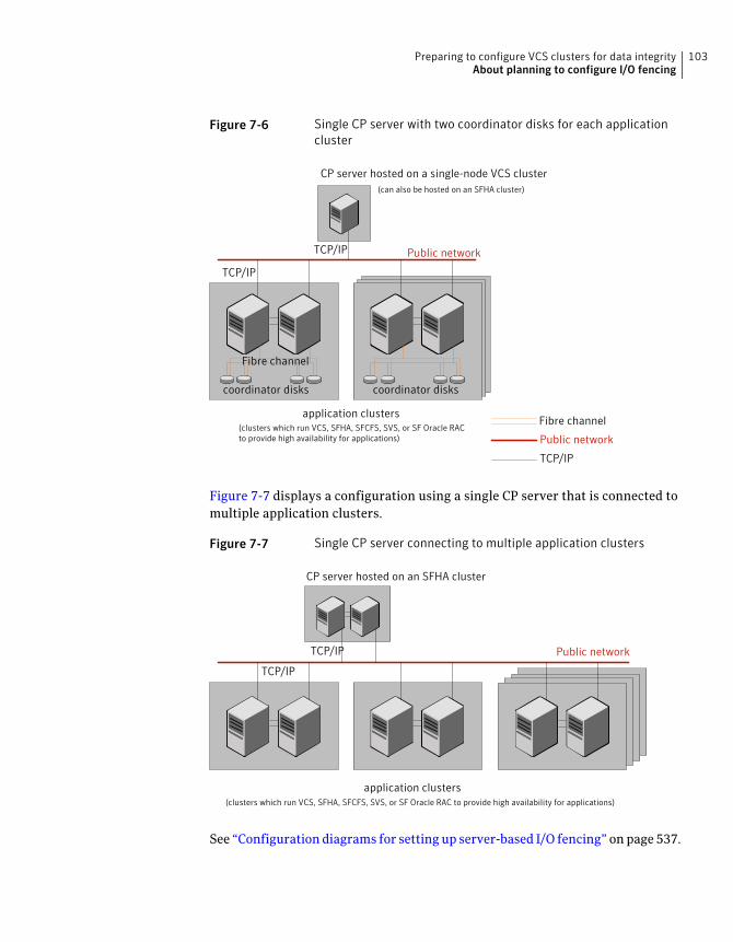
Figure 7-6 Single CP server with two coordinator disks for each applicationcluster
CP server hosted on a single-node VCS cluster
Public network
TCP/IP
TCP/IP
Fibre channel
Public network
TCP/IP
application clusters(clusters which run VCS, SFHA, SFCFS, SVS, or SF Oracle RACto provide high availability for applications)
Fibre channel
coordinator diskscoordinator disks
(can also be hosted on an SFHA cluster)
Figure 7-7 displays a configuration using a single CP server that is connected tomultiple application clusters.
Figure 7-7 Single CP server connecting to multiple application clusters
Public networkTCP/IP
TCP/IP
CP server hosted on an SFHA cluster
application clusters(clusters which run VCS, SFHA, SFCFS, SVS, or SF Oracle RAC to provide high availability for applications)
See “Configuration diagrams for setting up server-based I/O fencing” on page 537.
103Preparing to configure VCS clusters for data integrityAbout planning to configure I/O fencing
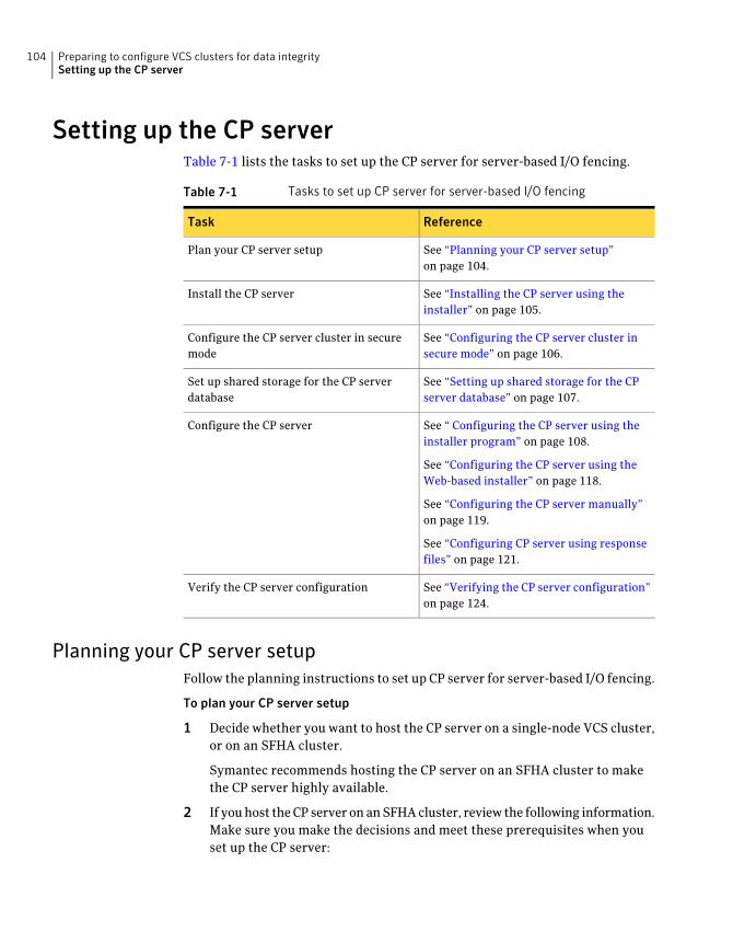
Setting up the CP serverTable 7-1 lists the tasks to set up the CP server for server-based I/O fencing.
Table 7-1 Tasks to set up CP server for server-based I/O fencing
ReferenceTask
See “Planning your CP server setup”on page 104.
Plan your CP server setup
See “Installing the CP server using theinstaller” on page 105.
Install the CP server
See “Configuring the CP server cluster insecure mode” on page 106.
Configure the CP server cluster in securemode
See “Setting up shared storage for the CPserver database” on page 107.
Set up shared storage for the CP serverdatabase
See “ Configuring the CP server using theinstaller program” on page 108.
See “Configuring the CP server using theWeb-based installer” on page 118.
See “Configuring the CP server manually”on page 119.
See “Configuring CP server using responsefiles” on page 121.
Configure the CP server
See “Verifying the CP server configuration”on page 124.
Verify the CP server configuration
Planning your CP server setupFollow the planning instructions to set up CP server for server-based I/O fencing.
To plan your CP server setup
1 Decide whether you want to host the CP server on a single-node VCS cluster,or on an SFHA cluster.
Symantec recommends hosting the CP server on an SFHA cluster to makethe CP server highly available.
2 If you host the CP server on an SFHA cluster, review the following information.Make sure you make the decisions and meet these prerequisites when youset up the CP server:
Preparing to configure VCS clusters for data integritySetting up the CP server
104
■ You must set up shared storage for the CP server database during yourCP server setup.
■ Decide whether you want to configure server-based fencing for the VCScluster (application cluster) with a single CP server as coordination pointor with at least three coordination points.Symantec recommends using at least three coordination points.
3 Decide whether you want to configure the CP server cluster in secure mode.
Symantec recommends configuring the CP server cluster in secure mode tosecure the communication between the CP server and its clients (VCS clusters).It also secures the HAD communication on the CP server cluster.
4 Set up the hardware and network for your CP server.
See “CP server requirements” on page 38.
5 Have the following information handy for CP server configuration:
■ Name for the CP serverThe CP server name should not contain any special characters. CP servername can include alphanumeric characters, underscore, and hyphen.
■ Port number for the CP serverAllocate a TCP/IP port for use by the CP server.Valid port range is between 49152 and 65535. The default port number is14250.
■ Virtual IP address, network interface, netmask, and networkhosts for theCP serverYou can configure multiple virtual IP addresses for the CP server.
Installing the CP server using the installerPerform the following procedure to install and configure VCS or SFHA on CPserver systems.
To install and configure VCS or SFHA on the CP server systems
◆ Depending on whether your CP server uses a single system or multiplesystems, perform the following tasks:
105Preparing to configure VCS clusters for data integritySetting up the CP server
Install and configure VCS to create a single-node VCS cluster.
During installation, make sure to select all packages for installation. The VRTScps packageis installed only if you select to install all packages.
Proceed to configure the CP server.
See “ Configuring the CP server using the installer program” on page 108.
See “Configuring the CP server manually” on page 119.
CP server setup uses asingle system
Install and configure SFHA to create an SFHA cluster. This makes the CP server highlyavailable.
Meet the following requirements for CP server:
■ During installation, make sure to select all packages for installation. The VRTScpspackage is installed only if you select to install all packages.
■ During configuration, configure disk-based fencing (scsi3 mode).
See theVeritasStorageFoundationandHighAvailability InstallationGuide for instructionson installing and configuring SFHA.
Proceed to set up shared storage for the CP server database.
CP server setup usesmultiple systems
Configuring the CP server cluster in secure modeYou must configure security on the CP server only if you want to secure thecommunication between the CP server and the VCS cluster (CP client).
This step secures the HAD communication on the CP server cluster.
Note: If you already configured the CP server cluster in secure mode during theVCS configuration, then skip this section.
Preparing to configure VCS clusters for data integritySetting up the CP server
106
To configure the CP server cluster in secure mode
◆ Run the installer as follows to configure the CP server cluster in secure mode.
If you have VCS installed on the CP server, run the following command:
# /opt/VRTS/install/installvcs<version> -security
Where <version> is the specific release version.
See “About the Veritas installer” on page 46.
If you have SFHA installed on the CP server, run the following command:
# /opt/VRTS/install/installsfha<version> -security
Where <version> is the specific release version.
See “About the Veritas installer” on page 46.
Setting up shared storage for the CP server databaseIf you configured SFHA on the CP server cluster, perform the following procedureto set up shared storage for the CP server database.
Symantec recommends that you create a mirrored volume for the CP serverdatabase and that you use the VxFS file system type.
107Preparing to configure VCS clusters for data integritySetting up the CP server
To set up shared storage for the CP server database
1 Create a disk group containing the disks. You require two disks to create amirrored volume.
For example:
# vxdg init cps_dg disk1 disk2
2 Create a mirrored volume over the disk group.
For example:
# vxassist -g cps_dg make cps_vol volume_size layout=mirror
3 Create a file system over the volume.
The CP server configuration utility only supports vxfs file system type. If youuse an alternate file system, then you must configure CP server manually.
Depending on the operating system that your CP server runs, enter thefollowing command:
# mkfs -V vxfs /dev/vx/rdsk/cps_dg/cps_volumeAIX
# mkfs -F vxfs /dev/vx/rdsk/cps_dg/cps_volumeHP-UX
# mkfs -t vxfs /dev/vx/rdsk/cps_dg/cps_volumeLinux
# mkfs -F vxfs /dev/vx/rdsk/cps_dg/cps_volumeSolaris
Configuring the CP server using the installer programUse the configcps option available in the installer program to configure the CPserver.
Perform one of the following procedures:
See “To configure the CP server on a single-node VCS cluster”on page 109.
For CP servers onsingle-node VCScluster:
See “To configure the CP server on an SFHA cluster” on page 113.For CP servers on anSFHA cluster:
Preparing to configure VCS clusters for data integritySetting up the CP server
108
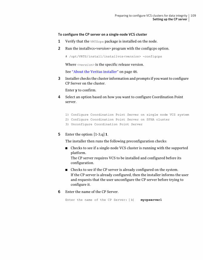
To configure the CP server on a single-node VCS cluster
1 Verify that the VRTScps package is installed on the node.
2 Run the installvcs<version> program with the configcps option.
# /opt/VRTS/install/installvcs<version> -configcps
Where <version> is the specific release version.
See “About the Veritas installer” on page 46.
3 Installer checks the cluster information and prompts if you want to configureCP Server on the cluster.
Enter y to confirm.
4 Select an option based on how you want to configure Coordination Pointserver.
1) Configure Coordination Point Server on single node VCS system
2) Configure Coordination Point Server on SFHA cluster
3) Unconfigure Coordination Point Server
5 Enter the option: [1-3,q] 1.
The installer then runs the following preconfiguration checks:
■ Checks to see if a single-node VCS cluster is running with the supportedplatform.The CP server requires VCS to be installed and configured before itsconfiguration.
■ Checks to see if the CP server is already configured on the system.If the CP server is already configured, then the installer informs the userand requests that the user unconfigure the CP server before trying toconfigure it.
6 Enter the name of the CP Server.
Enter the name of the CP Server: [b] mycpserver1
109Preparing to configure VCS clusters for data integritySetting up the CP server
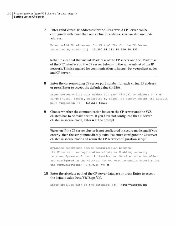
7 Enter valid virtual IP addresses for the CP Server. A CP Server can beconfigured with more than one virtual IP address. You can also use IPv6address.
Enter valid IP addresses for Virtual IPs for the CP Server,
separated by space [b] 10.200.58.231 10.200.58.232
Note: Ensure that the virtual IP address of the CP server and the IP addressof the NIC interface on the CP server belongs to the same subnet of the IPnetwork. This is required for communication to happen between client nodesand CP server.
8 Enter the corresponding CP server port number for each virtual IP addressor press Enter to accept the default value (14250).
Enter corresponding port number for each Virtual IP address in the
range [49152, 65535], separated by space, or simply accept the default
port suggested: [b] (14250) 65535
9 Choose whether the communication between the CP server and the VCSclusters has to be made secure. If you have not configured the CP servercluster in secure mode, enter n at the prompt.
Warning: If the CP server cluster is not configured in secure mode, and if youenter y, then the script immediately exits. You must configure the CP servercluster in secure mode and rerun the CP server configuration script.
Symantec recommends secure communication between
the CP server and application clusters. Enabling security
requires Symantec Product Authentication Service to be installed
and configured on the cluster. Do you want to enable Security for
the communications? [y,n,q,b] (y) n
10 Enter the absolute path of the CP server database or press Enter to acceptthe default value (/etc/VRTScps/db).
Enter absolute path of the database: [b] (/etc/VRTScps/db)
Preparing to configure VCS clusters for data integritySetting up the CP server
110
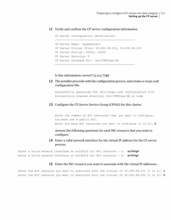
11 Verify and confirm the CP server configuration information.
CP Server configuration verification:
-------------------------------------------------
CP Server Name: mycpserver1
CP Server Virtual IP(s): 10.200.58.231, 10.200.58.232
CP Server Port(s): 65535, 14250
CP Server Security: 0
CP Server Database Dir: /etc/VRTScps/db
-------------------------------------------------
Is this information correct? [y,n,q,?] (y)
12 The installer proceeds with the configuration process, and creates a vxcps.confconfiguration file.
Successfully generated the /etc/vxcps.conf configuration file
Successfully created directory /etc/VRTScps/db on node
13 Configure the CP Server Service Group (CPSSG) for this cluster.
Enter the number of NIC resources that you want to configure.
You must use a public NIC.
Enter how many NIC resources you want to configure (1 to 2): 2
Answer the following questions for each NIC resource that you want toconfigure.
14 Enter a valid network interface for the virtual IP address for the CP serverprocess.
Enter a valid network interface on sol92216 for NIC resource - 1: e1000g0
Enter a valid network interface on sol92216 for NIC resource - 2: e1000g1
15 Enter the NIC resource you want to associate with the virtual IP addresses.
Enter the NIC resource you want to associate with the virtual IP 10.200.58.231 (1 to 2): 1
Enter the NIC resource you want to associate with the virtual IP 10.200.58.232 (1 to 2): 2
111Preparing to configure VCS clusters for data integritySetting up the CP server
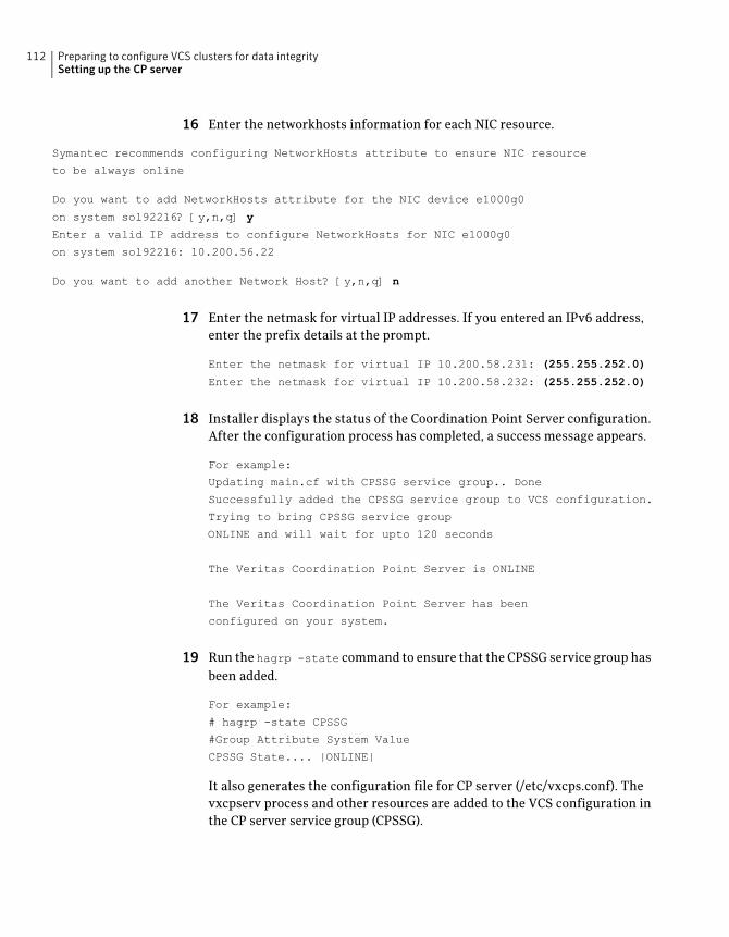
16 Enter the networkhosts information for each NIC resource.
Symantec recommends configuring NetworkHosts attribute to ensure NIC resource
to be always online
Do you want to add NetworkHosts attribute for the NIC device e1000g0
on system sol92216? [y,n,q] y
Enter a valid IP address to configure NetworkHosts for NIC e1000g0
on system sol92216: 10.200.56.22
Do you want to add another Network Host? [y,n,q] n
17 Enter the netmask for virtual IP addresses. If you entered an IPv6 address,enter the prefix details at the prompt.
Enter the netmask for virtual IP 10.200.58.231: (255.255.252.0)
Enter the netmask for virtual IP 10.200.58.232: (255.255.252.0)
18 Installer displays the status of the Coordination Point Server configuration.After the configuration process has completed, a success message appears.
For example:
Updating main.cf with CPSSG service group.. Done
Successfully added the CPSSG service group to VCS configuration.
Trying to bring CPSSG service group
ONLINE and will wait for upto 120 seconds
The Veritas Coordination Point Server is ONLINE
The Veritas Coordination Point Server has been
configured on your system.
19 Run the hagrp -state command to ensure that the CPSSG service group hasbeen added.
For example:
# hagrp -state CPSSG
#Group Attribute System Value
CPSSG State.... |ONLINE|
It also generates the configuration file for CP server (/etc/vxcps.conf). Thevxcpserv process and other resources are added to the VCS configuration inthe CP server service group (CPSSG).
Preparing to configure VCS clusters for data integritySetting up the CP server
112
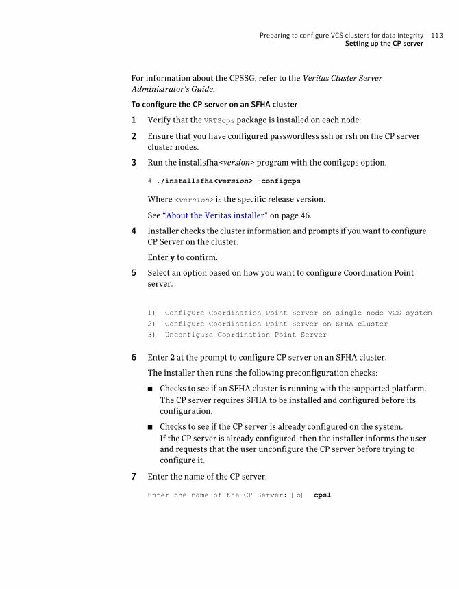
For information about the CPSSG, refer to the Veritas Cluster ServerAdministrator's Guide.
To configure the CP server on an SFHA cluster
1 Verify that the VRTScps package is installed on each node.
2 Ensure that you have configured passwordless ssh or rsh on the CP servercluster nodes.
3 Run the installsfha<version> program with the configcps option.
# ./installsfha<version> -configcps
Where <version> is the specific release version.
See “About the Veritas installer” on page 46.
4 Installer checks the cluster information and prompts if you want to configureCP Server on the cluster.
Enter y to confirm.
5 Select an option based on how you want to configure Coordination Pointserver.
1) Configure Coordination Point Server on single node VCS system
2) Configure Coordination Point Server on SFHA cluster
3) Unconfigure Coordination Point Server
6 Enter 2 at the prompt to configure CP server on an SFHA cluster.
The installer then runs the following preconfiguration checks:
■ Checks to see if an SFHA cluster is running with the supported platform.The CP server requires SFHA to be installed and configured before itsconfiguration.
■ Checks to see if the CP server is already configured on the system.If the CP server is already configured, then the installer informs the userand requests that the user unconfigure the CP server before trying toconfigure it.
7 Enter the name of the CP server.
Enter the name of the CP Server: [b] cps1
113Preparing to configure VCS clusters for data integritySetting up the CP server
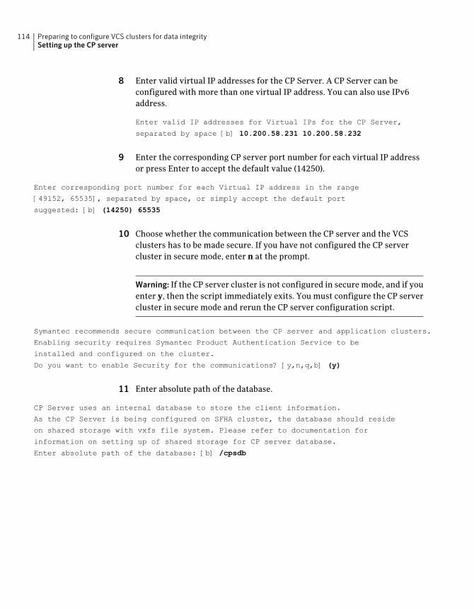
8 Enter valid virtual IP addresses for the CP Server. A CP Server can beconfigured with more than one virtual IP address. You can also use IPv6address.
Enter valid IP addresses for Virtual IPs for the CP Server,
separated by space [b] 10.200.58.231 10.200.58.232
9 Enter the corresponding CP server port number for each virtual IP addressor press Enter to accept the default value (14250).
Enter corresponding port number for each Virtual IP address in the range
[49152, 65535], separated by space, or simply accept the default port
suggested: [b] (14250) 65535
10 Choose whether the communication between the CP server and the VCSclusters has to be made secure. If you have not configured the CP servercluster in secure mode, enter n at the prompt.
Warning: If the CP server cluster is not configured in secure mode, and if youenter y, then the script immediately exits. You must configure the CP servercluster in secure mode and rerun the CP server configuration script.
Symantec recommends secure communication between the CP server and application clusters.
Enabling security requires Symantec Product Authentication Service to be
installed and configured on the cluster.
Do you want to enable Security for the communications? [y,n,q,b] (y)
11 Enter absolute path of the database.
CP Server uses an internal database to store the client information.
As the CP Server is being configured on SFHA cluster, the database should reside
on shared storage with vxfs file system. Please refer to documentation for
information on setting up of shared storage for CP server database.
Enter absolute path of the database: [b] /cpsdb
Preparing to configure VCS clusters for data integritySetting up the CP server
114
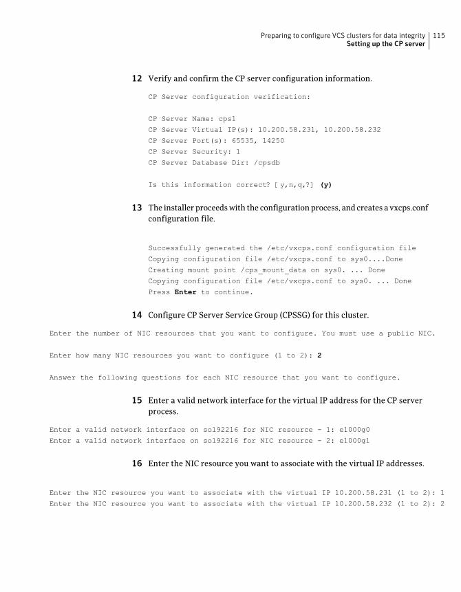
12 Verify and confirm the CP server configuration information.
CP Server configuration verification:
CP Server Name: cps1
CP Server Virtual IP(s): 10.200.58.231, 10.200.58.232
CP Server Port(s): 65535, 14250
CP Server Security: 1
CP Server Database Dir: /cpsdb
Is this information correct? [y,n,q,?] (y)
13 The installer proceeds with the configuration process, and creates a vxcps.confconfiguration file.
Successfully generated the /etc/vxcps.conf configuration file
Copying configuration file /etc/vxcps.conf to sys0....Done
Creating mount point /cps_mount_data on sys0. ... Done
Copying configuration file /etc/vxcps.conf to sys0. ... Done
Press Enter to continue.
14 Configure CP Server Service Group (CPSSG) for this cluster.
Enter the number of NIC resources that you want to configure. You must use a public NIC.
Enter how many NIC resources you want to configure (1 to 2): 2
Answer the following questions for each NIC resource that you want to configure.
15 Enter a valid network interface for the virtual IP address for the CP serverprocess.
Enter a valid network interface on sol92216 for NIC resource - 1: e1000g0
Enter a valid network interface on sol92216 for NIC resource - 2: e1000g1
16 Enter the NIC resource you want to associate with the virtual IP addresses.
Enter the NIC resource you want to associate with the virtual IP 10.200.58.231 (1 to 2): 1
Enter the NIC resource you want to associate with the virtual IP 10.200.58.232 (1 to 2): 2
115Preparing to configure VCS clusters for data integritySetting up the CP server

17 Enter the networkhosts information for each NIC resource.
Symantec recommends configuring NetworkHosts attribute to ensure NIC resource
to be always online
Do you want to add NetworkHosts attribute for the NIC device e1000g0
on system sol92216? [y,n,q] y
Enter a valid IP address to configure NetworkHosts for NIC e1000g0
on system sol92216: 10.200.56.22
Do you want to add another Network Host? [y,n,q] n
Do you want to apply the same NetworkHosts for all systems? [y,n,q] (y)
18 Enter the netmask for virtual IP addresses. If you entered an IPv6 address,enter the prefix details at the prompt.
Enter the netmask for virtual IP 10.200.58.231: (255.255.252.0)
Enter the netmask for virtual IP 10.200.58.232: (255.255.252.0)
19 Configure a disk group for CP server database. You can choose an existingdisk group or create a new disk group.
Symantec recommends to use the disk group that has at least
two disks on which mirrored volume can be created.
Select one of the options below for CP Server database disk group:
1) Create a new disk group
2) Using an existing disk group
Enter the choice for a disk group: [1-2,q] 2
20 Select one disk group as the CP Server database disk group.
Select one disk group as CP Server database disk group: [1-3,q] 3
1) mycpsdg
2) cpsdg1
3) newcpsdg
Preparing to configure VCS clusters for data integritySetting up the CP server
116
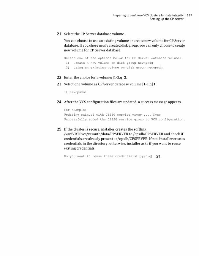
21 Select the CP Server database volume.
You can choose to use an existing volume or create new volume for CP Serverdatabase. If you chose newly created disk group, you can only choose to createnew volume for CP Server database.
Select one of the options below for CP Server database volume:
1) Create a new volume on disk group newcpsdg
2) Using an existing volume on disk group newcpsdg
22 Enter the choice for a volume: [1-2,q] 2.
23 Select one volume as CP Server database volume [1-1,q] 1
1) newcpsvol
24 After the VCS configuration files are updated, a success message appears.
For example:
Updating main.cf with CPSSG service group .... Done
Successfully added the CPSSG service group to VCS configuration.
25 If the cluster is secure, installer creates the softlink/var/VRTSvcs/vcsauth/data/CPSERVER to /cpsdb/CPSERVER and check ifcredentials are already present at /cpsdb/CPSERVER. If not, installer createscredentials in the directory, otherwise, installer asks if you want to reuseexsting credentials.
Do you want to reuse these credentials? [y,n,q] (y)
117Preparing to configure VCS clusters for data integritySetting up the CP server
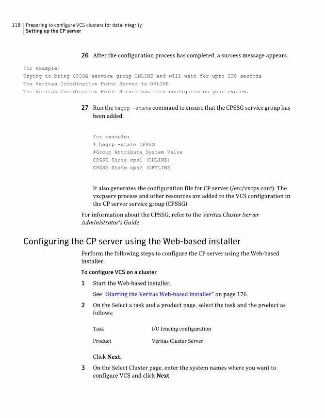
26 After the configuration process has completed, a success message appears.
For example:
Trying to bring CPSSG service group ONLINE and will wait for upto 120 seconds
The Veritas Coordination Point Server is ONLINE
The Veritas Coordination Point Server has been configured on your system.
27 Run the hagrp -state command to ensure that the CPSSG service group hasbeen added.
For example:
# hagrp -state CPSSG
#Group Attribute System Value
CPSSG State cps1 |ONLINE|
CPSSG State cps2 |OFFLINE|
It also generates the configuration file for CP server (/etc/vxcps.conf). Thevxcpserv process and other resources are added to the VCS configuration inthe CP server service group (CPSSG).
For information about the CPSSG, refer to the Veritas Cluster ServerAdministrator's Guide.
Configuring the CP server using the Web-based installerPerform the following steps to configure the CP server using the Web-basedinstaller.
To configure VCS on a cluster
1 Start the Web-based installer.
See “Starting the Veritas Web-based installer” on page 176.
2 On the Select a task and a product page, select the task and the product asfollows:
I/O fencing configurationTask
Veritas Cluster ServerProduct
Click Next.
3 On the Select Cluster page, enter the system names where you want toconfigure VCS and click Next.
Preparing to configure VCS clusters for data integritySetting up the CP server
118
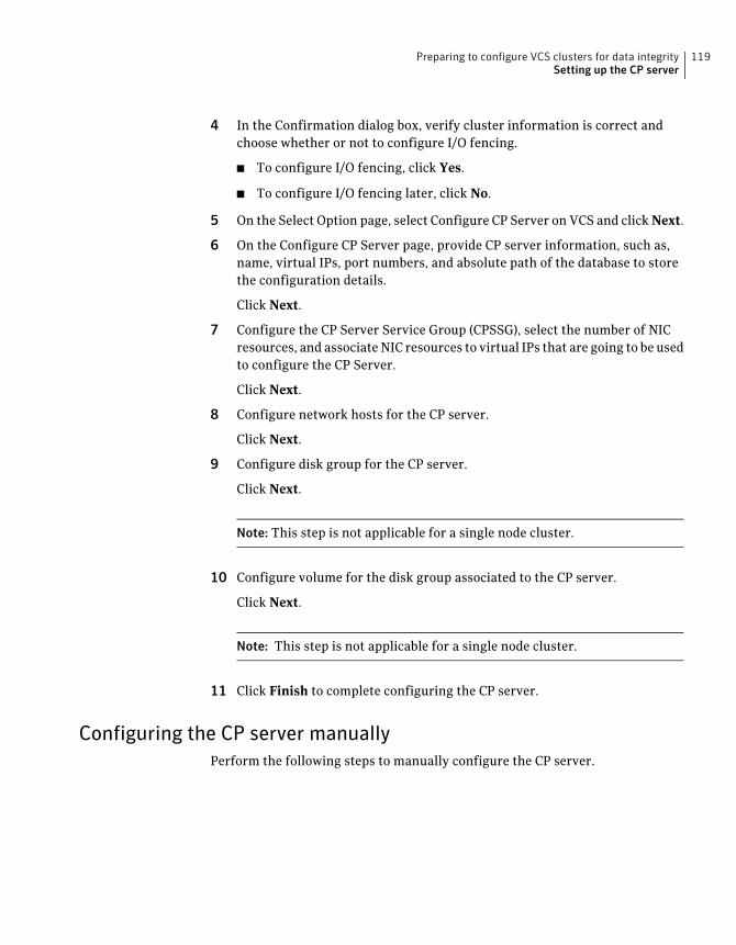
4 In the Confirmation dialog box, verify cluster information is correct andchoose whether or not to configure I/O fencing.
■ To configure I/O fencing, click Yes.
■ To configure I/O fencing later, click No.
5 On the Select Option page, select Configure CP Server on VCS and click Next.
6 On the Configure CP Server page, provide CP server information, such as,name, virtual IPs, port numbers, and absolute path of the database to storethe configuration details.
Click Next.
7 Configure the CP Server Service Group (CPSSG), select the number of NICresources, and associate NIC resources to virtual IPs that are going to be usedto configure the CP Server.
Click Next.
8 Configure network hosts for the CP server.
Click Next.
9 Configure disk group for the CP server.
Click Next.
Note: This step is not applicable for a single node cluster.
10 Configure volume for the disk group associated to the CP server.
Click Next.
Note: This step is not applicable for a single node cluster.
11 Click Finish to complete configuring the CP server.
Configuring the CP server manuallyPerform the following steps to manually configure the CP server.
119Preparing to configure VCS clusters for data integritySetting up the CP server
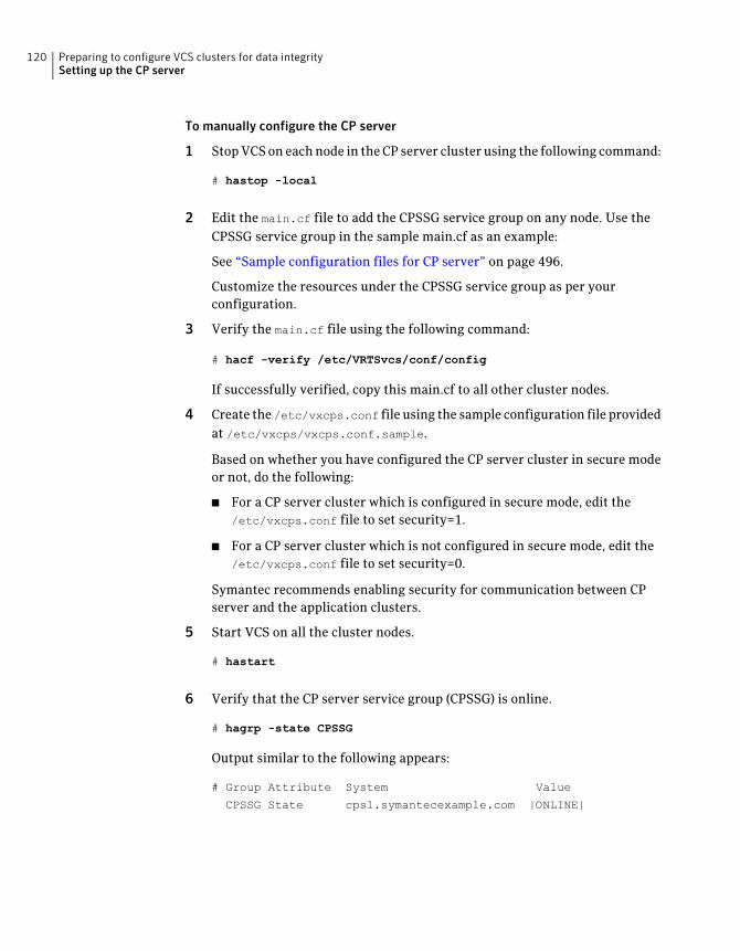
To manually configure the CP server
1 Stop VCS on each node in the CP server cluster using the following command:
# hastop -local
2 Edit the main.cf file to add the CPSSG service group on any node. Use theCPSSG service group in the sample main.cf as an example:
See “Sample configuration files for CP server” on page 496.
Customize the resources under the CPSSG service group as per yourconfiguration.
3 Verify the main.cf file using the following command:
# hacf -verify /etc/VRTSvcs/conf/config
If successfully verified, copy this main.cf to all other cluster nodes.
4 Create the /etc/vxcps.conf file using the sample configuration file providedat /etc/vxcps/vxcps.conf.sample.
Based on whether you have configured the CP server cluster in secure modeor not, do the following:
■ For a CP server cluster which is configured in secure mode, edit the/etc/vxcps.conf file to set security=1.
■ For a CP server cluster which is not configured in secure mode, edit the/etc/vxcps.conf file to set security=0.
Symantec recommends enabling security for communication between CPserver and the application clusters.
5 Start VCS on all the cluster nodes.
# hastart
6 Verify that the CP server service group (CPSSG) is online.
# hagrp -state CPSSG
Output similar to the following appears:
# Group Attribute System Value
CPSSG State cps1.symantecexample.com |ONLINE|
Preparing to configure VCS clusters for data integritySetting up the CP server
120
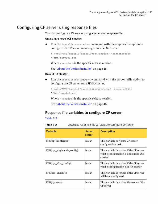
Configuring CP server using response filesYou can configure a CP server using a generated responsefile.
On a single node VCS cluster:
◆ Run the installvcs<version> command with the responsefile option toconfigure the CP server on a single node VCS cluster.
# /opt/VRTS/install/installvcs<version> -responsefile
'/tmp/sample1.res'
Where <version> is the specific release version.
See “About the Veritas installer” on page 46.
On a SFHA cluster:
◆ Run the installsfha<version> command with the responsefile option toconfigure the CP server on a SFHA cluster.
# /opt/VRTS/install/installsfha<version> -responsefile
'/tmp/sample1.res'
Where <version> is the specific release version.
See “About the Veritas installer” on page 46.
Response file variables to configure CP serverTable 7-2
Table 7-2 describes response file variables to configure CP server
DescriptionList orScalar
Variable
This variable performs CP serverconfiguration task
ScalarCFG{opt}{configcps}
This variable describes if the CP serverwill be configured on a singlenode VCScluster
ScalarCFG{cps_singlenode_config}
This variable describes if the CP serverwill be configured on a SFHA cluster
ScalarCFG{cps_sfha_config}
This variable describes if the CP serverwill be unconfigured
ScalarCFG{cps_unconfig}
This variable describes the name of theCP server
ScalarCFG{cpsname}
121Preparing to configure VCS clusters for data integritySetting up the CP server
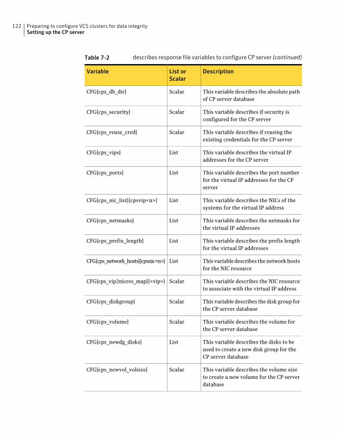
Table 7-2 describes response file variables to configure CP server (continued)
DescriptionList orScalar
Variable
This variable describes the absolute pathof CP server database
ScalarCFG{cps_db_dir}
This variable describes if security isconfigured for the CP server
ScalarCFG{cps_security}
This variable describes if reusing theexisting credentials for the CP server
ScalarCFG{cps_reuse_cred}
This variable describes the virtual IPaddresses for the CP server
ListCFG{cps_vips}
This variable describes the port numberfor the virtual IP addresses for the CPserver
ListCFG{cps_ports}
This variable describes the NICs of thesystems for the virtual IP address
ListCFG{cps_nic_list}{cpsvip<n>}
This variable describes the netmasks forthe virtual IP addresses
ListCFG{cps_netmasks}
This variable describes the prefix lengthfor the virtual IP addresses
ListCFG{cps_prefix_length}
This variable describes the network hostsfor the NIC resource
ListCFG{cps_network_hosts}{cpsnic<n>}
This variable describes the NIC resourceto associate with the virtual IP address
ScalarCFG{cps_vip2nicres_map}{<vip>}
This variable describes the disk group forthe CP server database
ScalarCFG{cps_diskgroup}
This variable describes the volume forthe CP server database
ScalarCFG{cps_volume}
This variable describes the disks to beused to create a new disk group for theCP server database
ListCFG{cps_newdg_disks}
This variable describes the volume sizeto create a new volume for the CP serverdatabase
ScalarCFG{cps_newvol_volsize}
Preparing to configure VCS clusters for data integritySetting up the CP server
122
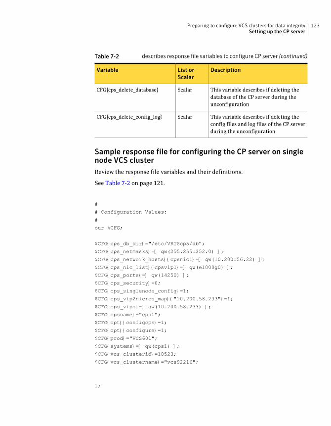
Table 7-2 describes response file variables to configure CP server (continued)
DescriptionList orScalar
Variable
This variable describes if deleting thedatabase of the CP server during theunconfiguration
ScalarCFG{cps_delete_database}
This variable describes if deleting theconfig files and log files of the CP serverduring the unconfiguration
ScalarCFG{cps_delete_config_log}
Sample response file for configuring the CP server on singlenode VCS clusterReview the response file variables and their definitions.
See Table 7-2 on page 121.
#
# Configuration Values:
#
our %CFG;
$CFG{cps_db_dir}="/etc/VRTScps/db";
$CFG{cps_netmasks}=[ qw(255.255.252.0) ];
$CFG{cps_network_hosts}{cpsnic1}=[ qw(10.200.56.22) ];
$CFG{cps_nic_list}{cpsvip1}=[ qw(e1000g0) ];
$CFG{cps_ports}=[ qw(14250) ];
$CFG{cps_security}=0;
$CFG{cps_singlenode_config}=1;
$CFG{cps_vip2nicres_map}{"10.200.58.233"}=1;
$CFG{cps_vips}=[ qw(10.200.58.233) ];
$CFG{cpsname}="cps1";
$CFG{opt}{configcps}=1;
$CFG{opt}{configure}=1;
$CFG{prod}="VCS601";
$CFG{systems}=[ qw(cps1) ];
$CFG{vcs_clusterid}=18523;
$CFG{vcs_clustername}="vcs92216";
1;
123Preparing to configure VCS clusters for data integritySetting up the CP server
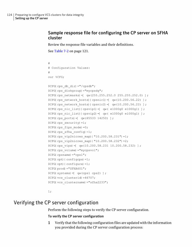
Sample response file for configuring the CP server on SFHAclusterReview the response file variables and their definitions.
See Table 7-2 on page 121.
#
# Configuration Values:
#
our %CFG;
$CFG{cps_db_dir}="/cpsdb";
$CFG{cps_diskgroup}="mycpsdg";
$CFG{cps_netmasks}=[ qw(255.255.252.0 255.255.252.0) ];
$CFG{cps_network_hosts}{cpsnic1}=[ qw(10.200.56.22) ];
$CFG{cps_network_hosts}{cpsnic2}=[ qw(10.200.56.22) ];
$CFG{cps_nic_list}{cpsvip1}=[ qw( e1000g0 e1000g1) ];
$CFG{cps_nic_list}{cpsvip2}=[ qw( e1000g0 e1000g1) ];
$CFG{cps_ports}=[ qw(65533 14250) ];
$CFG{cps_security}=1;
$CFG{cps_fips_mode}=0;
$CFG{cps_sfha_config}=1;
$CFG{cps_vip2nicres_map}{"10.200.58.231"}=1;
$CFG{cps_vip2nicres_map}{"10.200.58.232"}=2;
$CFG{cps_vips}=[ qw(10.200.58.231 10.200.58.232) ];
$CFG{cps_volume}="mycpsvol";
$CFG{cpsname}="cps1";
$CFG{opt}{configcps}=1;
$CFG{opt}{configure}=1;
$CFG{prod}="SFHA601";
$CFG{systems}=[ qw(cps1 cps2) ];
$CFG{vcs_clusterid}=46707;
$CFG{vcs_clustername}="sfha2233";
1;
Verifying the CP server configurationPerform the following steps to verify the CP server configuration.
To verify the CP server configuration
1 Verify that the following configuration files are updated with the informationyou provided during the CP server configuration process:
Preparing to configure VCS clusters for data integritySetting up the CP server
124
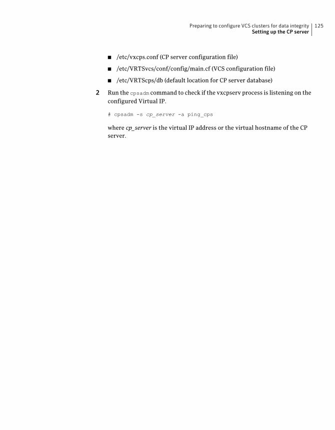
■ /etc/vxcps.conf (CP server configuration file)
■ /etc/VRTSvcs/conf/config/main.cf (VCS configuration file)
■ /etc/VRTScps/db (default location for CP server database)
2 Run the cpsadm command to check if the vxcpserv process is listening on theconfigured Virtual IP.
# cpsadm -s cp_server -a ping_cps
where cp_server is the virtual IP address or the virtual hostname of the CPserver.
125Preparing to configure VCS clusters for data integritySetting up the CP server

Preparing to configure VCS clusters for data integritySetting up the CP server
126
Configuring VCS
This chapter includes the following topics:
■ Overview of tasks to configure VCS using the script-based installer
■ Starting the software configuration
■ Specifying systems for configuration
■ Configuring the cluster name
■ Configuring private heartbeat links
■ Configuring the virtual IP of the cluster
■ Configuring Veritas Cluster Server in secure mode
■ Setting up trust relationships for your VCS cluster
■ Configuring a secure cluster node by node
■ Adding VCS users
■ Configuring SMTP email notification
■ Configuring SNMP trap notification
■ Configuring global clusters
■ Completing the VCS configuration
■ Verifying and updating licenses on the system
8Chapter
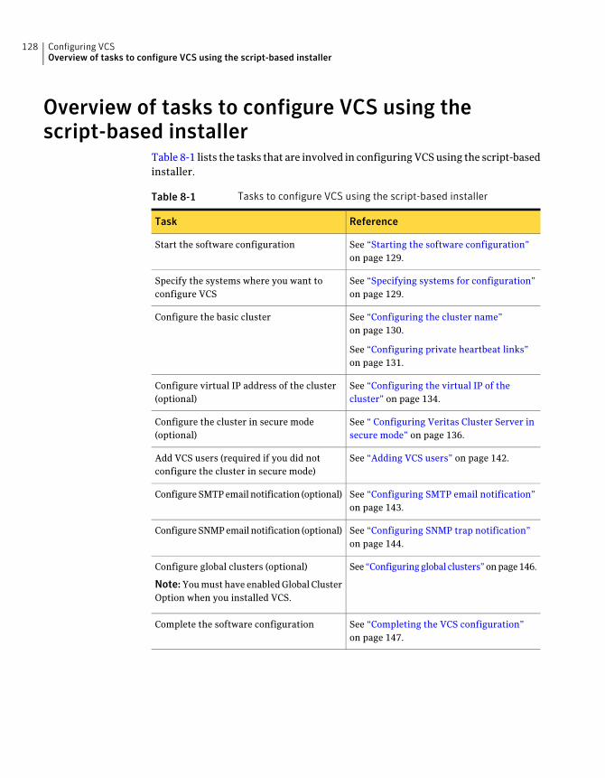
Overview of tasks to configure VCS using thescript-based installer
Table 8-1 lists the tasks that are involved in configuring VCS using the script-basedinstaller.
Table 8-1 Tasks to configure VCS using the script-based installer
ReferenceTask
See “Starting the software configuration”on page 129.
Start the software configuration
See “Specifying systems for configuration”on page 129.
Specify the systems where you want toconfigure VCS
See “Configuring the cluster name”on page 130.
See “Configuring private heartbeat links”on page 131.
Configure the basic cluster
See “Configuring the virtual IP of thecluster” on page 134.
Configure virtual IP address of the cluster(optional)
See “ Configuring Veritas Cluster Server insecure mode” on page 136.
Configure the cluster in secure mode(optional)
See “Adding VCS users” on page 142.Add VCS users (required if you did notconfigure the cluster in secure mode)
See “Configuring SMTP email notification”on page 143.
Configure SMTP email notification (optional)
See “Configuring SNMP trap notification”on page 144.
Configure SNMP email notification (optional)
See “Configuring global clusters” on page 146.Configure global clusters (optional)
Note: You must have enabled Global ClusterOption when you installed VCS.
See “Completing the VCS configuration”on page 147.
Complete the software configuration
Configuring VCSOverview of tasks to configure VCS using the script-based installer
128
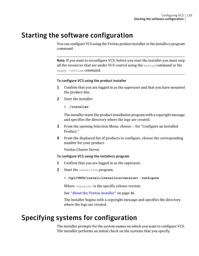
Starting the software configurationYou can configure VCS using the Veritas product installer or the installvcs programcommand.
Note: If you want to reconfigure VCS, before you start the installer you must stopall the resources that are under VCS control using the hastop command or thehagrp -offline command.
To configure VCS using the product installer
1 Confirm that you are logged in as the superuser and that you have mountedthe product disc.
2 Start the installer.
# ./installer
The installer starts the product installation program with a copyright messageand specifies the directory where the logs are created.
3 From the opening Selection Menu, choose: C for "Configure an InstalledProduct."
4 From the displayed list of products to configure, choose the correspondingnumber for your product:
Veritas Cluster Server
To configure VCS using the installvcs program
1 Confirm that you are logged in as the superuser.
2 Start the installvcs program.
# /opt/VRTS/install/installvcs<version> -configure
Where <version> is the specific release version.
See “About the Veritas installer” on page 46.
The installer begins with a copyright message and specifies the directorywhere the logs are created.
Specifying systems for configurationThe installer prompts for the system names on which you want to configure VCS.The installer performs an initial check on the systems that you specify.
129Configuring VCSStarting the software configuration
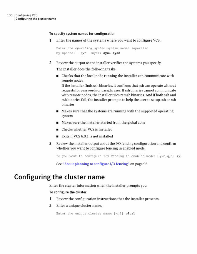
To specify system names for configuration
1 Enter the names of the systems where you want to configure VCS.
Enter the operating_system system names separated
by spaces: [q,?] (sys1) sys1 sys2
2 Review the output as the installer verifies the systems you specify.
The installer does the following tasks:
■ Checks that the local node running the installer can communicate withremote nodesIf the installer finds ssh binaries, it confirms that ssh can operate withoutrequests for passwords or passphrases. If ssh binaries cannot communicatewith remote nodes, the installer tries remsh binaries. And if both ssh andrsh binaries fail, the installer prompts to help the user to setup ssh or rshbinaries.
■ Makes sure that the systems are running with the supported operatingsystem
■ Makes sure the installer started from the global zone
■ Checks whether VCS is installed
■ Exits if VCS 6.0.1 is not installed
3 Review the installer output about the I/O fencing configuration and confirmwhether you want to configure fencing in enabled mode.
Do you want to configure I/O Fencing in enabled mode? [y,n,q,?] (y)
See “About planning to configure I/O fencing” on page 95.
Configuring the cluster nameEnter the cluster information when the installer prompts you.
To configure the cluster
1 Review the configuration instructions that the installer presents.
2 Enter a unique cluster name.
Enter the unique cluster name: [q,?] clus1
Configuring VCSConfiguring the cluster name
130
Configuring private heartbeat linksYou now configure the private heartbeat links that LLT uses. VCS provides theoption to use LLT over Ethernet or over UDP (User Datagram Protocol). Symantecrecommends that you configure heartbeat links that use LLT over Ethernet forhigh performance, unless hardware requirements force you to use LLT over UDP.If you want to configure LLT over UDP, make sure you meet the prerequisites.
See “Using the UDP layer for LLT” on page 507.
The following procedure helps you configure LLT over Ethernet.
To configure private heartbeat links
1 Choose one of the following options at the installer prompt based on whetheryou want to configure LLT over Ethernet or UDP.
■ Option 1: LLT over Ethernet (answer installer questions)Enter the heartbeat link details at the installer prompt to configure LLTover Ethernet.Skip to step 2.
■ Option 2: LLT over UDP (answer installer questions)Make sure that each NIC you want to use as heartbeat link has an IPaddress configured. Enter the heartbeat link details at the installer promptto configure LLT over UDP. If you had not already configured IP addressesto the NICs, the installer provides you an option to detect the IP addressfor a given NIC.Skip to step 3.
■ Option 3: Automatically detect configuration for LLT over EthernetAllow the installer to automatically detect the heartbeat link details toconfigure LLT over Ethernet. The installer tries to detect all connectedlinks between all systems.Skip to step 5.
Note: Option 3 is not available when the configuration is a single nodeconfiguration.
2 If you chose option 1, enter the network interface card details for the privateheartbeat links.
The installer discovers and lists the network interface cards.
Answer the installer prompts. The following example shows different NICsbased on architecture:
131Configuring VCSConfiguring private heartbeat links
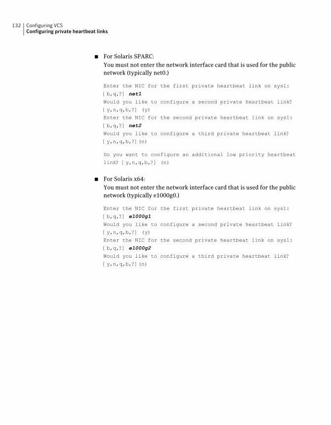
■ For Solaris SPARC:You must not enter the network interface card that is used for the publicnetwork (typically net0.)
Enter the NIC for the first private heartbeat link on sys1:
[b,q,?] net1
Would you like to configure a second private heartbeat link?
[y,n,q,b,?] (y)
Enter the NIC for the second private heartbeat link on sys1:
[b,q,?] net2
Would you like to configure a third private heartbeat link?
[y,n,q,b,?](n)
Do you want to configure an additional low priority heartbeat
link? [y,n,q,b,?] (n)
■ For Solaris x64:You must not enter the network interface card that is used for the publicnetwork (typically e1000g0.)
Enter the NIC for the first private heartbeat link on sys1:
[b,q,?] e1000g1
Would you like to configure a second private heartbeat link?
[y,n,q,b,?] (y)
Enter the NIC for the second private heartbeat link on sys1:
[b,q,?] e1000g2
Would you like to configure a third private heartbeat link?
[y,n,q,b,?](n)
Configuring VCSConfiguring private heartbeat links
132
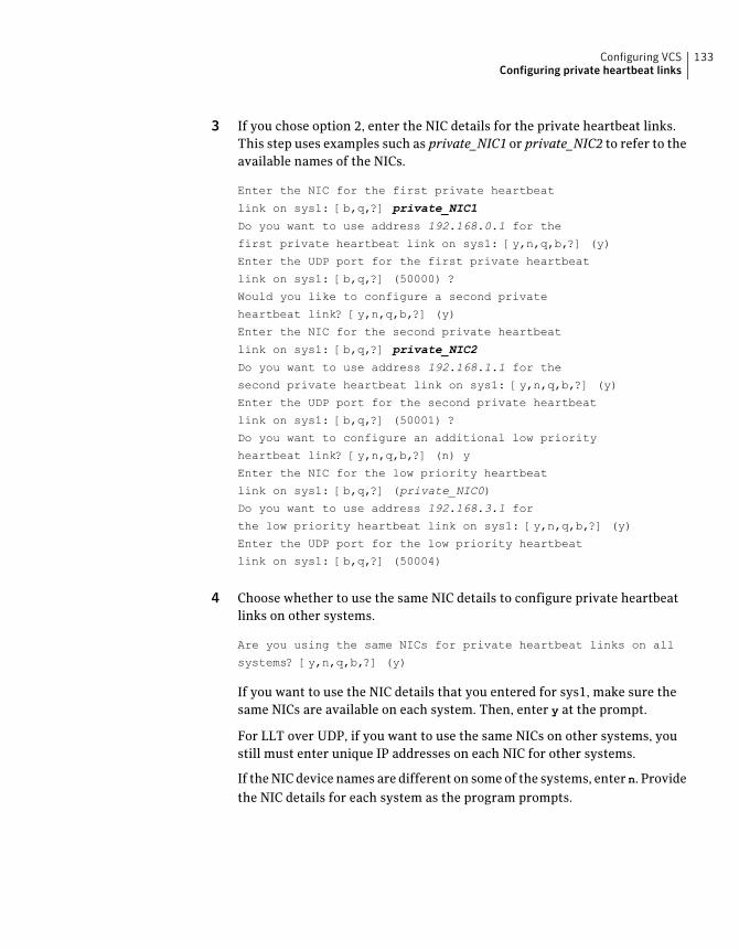
3 If you chose option 2, enter the NIC details for the private heartbeat links.This step uses examples such as private_NIC1 or private_NIC2 to refer to theavailable names of the NICs.
Enter the NIC for the first private heartbeat
link on sys1: [b,q,?] private_NIC1
Do you want to use address 192.168.0.1 for the
first private heartbeat link on sys1: [y,n,q,b,?] (y)
Enter the UDP port for the first private heartbeat
link on sys1: [b,q,?] (50000) ?
Would you like to configure a second private
heartbeat link? [y,n,q,b,?] (y)
Enter the NIC for the second private heartbeat
link on sys1: [b,q,?] private_NIC2
Do you want to use address 192.168.1.1 for the
second private heartbeat link on sys1: [y,n,q,b,?] (y)
Enter the UDP port for the second private heartbeat
link on sys1: [b,q,?] (50001) ?
Do you want to configure an additional low priority
heartbeat link? [y,n,q,b,?] (n) y
Enter the NIC for the low priority heartbeat
link on sys1: [b,q,?] (private_NIC0)
Do you want to use address 192.168.3.1 for
the low priority heartbeat link on sys1: [y,n,q,b,?] (y)
Enter the UDP port for the low priority heartbeat
link on sys1: [b,q,?] (50004)
4 Choose whether to use the same NIC details to configure private heartbeatlinks on other systems.
Are you using the same NICs for private heartbeat links on all
systems? [y,n,q,b,?] (y)
If you want to use the NIC details that you entered for sys1, make sure thesame NICs are available on each system. Then, enter y at the prompt.
For LLT over UDP, if you want to use the same NICs on other systems, youstill must enter unique IP addresses on each NIC for other systems.
If the NIC device names are different on some of the systems, enter n. Providethe NIC details for each system as the program prompts.
133Configuring VCSConfiguring private heartbeat links
5 If you chose option 3, the installer detects NICs on each system and networklinks, and sets link priority.
If the installer fails to detect heartbeat links or fails to find any high-prioritylinks, then choose option 1 or option 2 to manually configure the heartbeatlinks.
See step 2 for option 1, or step 3 for option 2.
6 Enter a unique cluster ID:
Enter a unique cluster ID number between 0-65535: [b,q,?] (60842)
The cluster cannot be configured if the cluster ID 60842 is in use by anothercluster. Installer performs a check to determine if the cluster ID is duplicate.The check takes less than a minute to complete.
Would you like to check if the cluster ID is in use by another
cluster? [y,n,q] (y)
7 Verify and confirm the information that the installer summarizes.
Configuring the virtual IP of the clusterYou can configure the virtual IP of the cluster to use to connect from the ClusterManager (Java Console), Veritas Operations Manager (VOM), or to specify in theRemoteGroup resource.
See theVeritasClusterServerAdministrator'sGuide for information on the ClusterManager.
See the Veritas Cluster Server Bundled Agents Reference Guide for informationon the RemoteGroup agent.
To configure the virtual IP of the cluster
1 Review the required information to configure the virtual IP of the cluster.
2 When the system prompts whether you want to configure the virtual IP, entery.
3 Confirm whether you want to use the discovered public NIC on the firstsystem.
Do one of the following:
■ If the discovered NIC is the one to use, press Enter.
■ If you want to use a different NIC, type the name of a NIC to use and pressEnter.
Configuring VCSConfiguring the virtual IP of the cluster
134
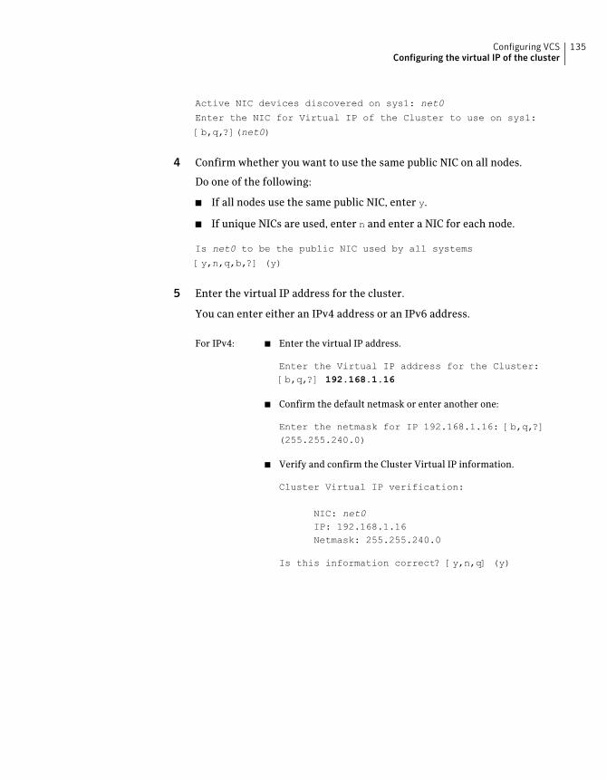
Active NIC devices discovered on sys1: net0
Enter the NIC for Virtual IP of the Cluster to use on sys1:
[b,q,?](net0)
4 Confirm whether you want to use the same public NIC on all nodes.
Do one of the following:
■ If all nodes use the same public NIC, enter y.
■ If unique NICs are used, enter n and enter a NIC for each node.
Is net0 to be the public NIC used by all systems
[y,n,q,b,?] (y)
5 Enter the virtual IP address for the cluster.
You can enter either an IPv4 address or an IPv6 address.
■ Enter the virtual IP address.
Enter the Virtual IP address for the Cluster:[b,q,?] 192.168.1.16
■ Confirm the default netmask or enter another one:
Enter the netmask for IP 192.168.1.16: [b,q,?](255.255.240.0)
■ Verify and confirm the Cluster Virtual IP information.
Cluster Virtual IP verification:
NIC: net0IP: 192.168.1.16Netmask: 255.255.240.0
Is this information correct? [y,n,q] (y)
For IPv4:
135Configuring VCSConfiguring the virtual IP of the cluster
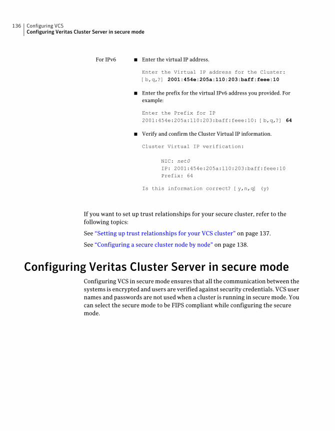
■ Enter the virtual IP address.
Enter the Virtual IP address for the Cluster:[b,q,?] 2001:454e:205a:110:203:baff:feee:10
■ Enter the prefix for the virtual IPv6 address you provided. Forexample:
Enter the Prefix for IP2001:454e:205a:110:203:baff:feee:10: [b,q,?] 64
■ Verify and confirm the Cluster Virtual IP information.
Cluster Virtual IP verification:
NIC: net0IP: 2001:454e:205a:110:203:baff:feee:10Prefix: 64
Is this information correct? [y,n,q] (y)
For IPv6
If you want to set up trust relationships for your secure cluster, refer to thefollowing topics:
See “Setting up trust relationships for your VCS cluster” on page 137.
See “Configuring a secure cluster node by node” on page 138.
Configuring Veritas Cluster Server in secure modeConfiguring VCS in secure mode ensures that all the communication between thesystems is encrypted and users are verified against security credentials. VCS usernames and passwords are not used when a cluster is running in secure mode. Youcan select the secure mode to be FIPS compliant while configuring the securemode.
Configuring VCSConfiguring Veritas Cluster Server in secure mode
136
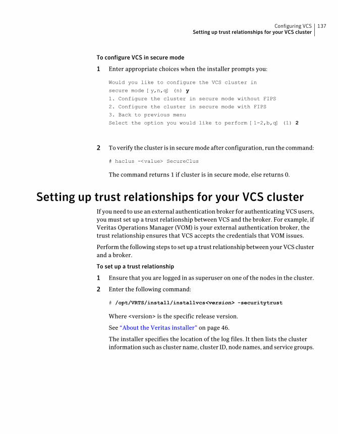
To configure VCS in secure mode
1 Enter appropriate choices when the installer prompts you:
Would you like to configure the VCS cluster in
secure mode [y,n,q] (n) y
1. Configure the cluster in secure mode without FIPS
2. Configure the cluster in secure mode with FIPS
3. Back to previous menu
Select the option you would like to perform [1-2,b,q] (1) 2
2 To verify the cluster is in secure mode after configuration, run the command:
# haclus -<value> SecureClus
The command returns 1 if cluster is in secure mode, else returns 0.
Setting up trust relationships for your VCS clusterIf you need to use an external authentication broker for authenticating VCS users,you must set up a trust relationship between VCS and the broker. For example, ifVeritas Operations Manager (VOM) is your external authentication broker, thetrust relationship ensures that VCS accepts the credentials that VOM issues.
Perform the following steps to set up a trust relationship between your VCS clusterand a broker.
To set up a trust relationship
1 Ensure that you are logged in as superuser on one of the nodes in the cluster.
2 Enter the following command:
# /opt/VRTS/install/installvcs<version> -securitytrust
Where <version> is the specific release version.
See “About the Veritas installer” on page 46.
The installer specifies the location of the log files. It then lists the clusterinformation such as cluster name, cluster ID, node names, and service groups.
137Configuring VCSSetting up trust relationships for your VCS cluster
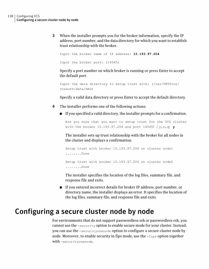
3 When the installer prompts you for the broker information, specify the IPaddress, port number, and the data directory for which you want to establishtrust relationship with the broker.
Input the broker name of IP address: 15.193.97.204
Input the broker port: (14545)
Specify a port number on which broker is running or press Enter to acceptthe default port.
Input the data directory to setup trust with: (/var/VRTSvcs/
vcsauth/data/HAD)
Specify a valid data directory or press Enter to accept the default directory.
4 The installer performs one of the following actions:
■ If you specified a valid directory, the installer prompts for a confirmation.
Are you sure that you want to setup trust for the VCS cluster
with the broker 15.193.97.204 and port 14545? [y,n,q] y
The installer sets up trust relationship with the broker for all nodes inthe cluster and displays a confirmation.
Setup trust with broker 15.193.97.204 on cluster node1
........Done
Setup trust with broker 15.193.97.204 on cluster node2
........Done
The installer specifies the location of the log files, summary file, andresponse file and exits.
■ If you entered incorrect details for broker IP address, port number, ordirectory name, the installer displays an error. It specifies the location ofthe log files, summary file, and response file and exits.
Configuring a secure cluster node by nodeFor environments that do not support passwordless ssh or passwordless rsh, youcannot use the -security option to enable secure mode for your cluster. Instead,you can use the -securityonenode option to configure a secure cluster node bynode. Moreover, to enable security in fips mode, use the -fips option togetherwith -securityonenode.
Configuring VCSConfiguring a secure cluster node by node
138
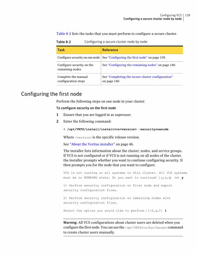
Table 8-2 lists the tasks that you must perform to configure a secure cluster.
Table 8-2 Configuring a secure cluster node by node
ReferenceTask
See “Configuring the first node” on page 139.Configure security on one node
See “Configuring the remaining nodes” on page 140.Configure security on theremaining nodes
See “Completing the secure cluster configuration”on page 140.
Complete the manualconfiguration steps
Configuring the first nodePerform the following steps on one node in your cluster.
To configure security on the first node
1 Ensure that you are logged in as superuser.
2 Enter the following command:
# /opt/VRTS/install/installvcs<version> -securityonenode
Where <version> is the specific release version.
See “About the Veritas installer” on page 46.
The installer lists information about the cluster, nodes, and service groups.If VCS is not configured or if VCS is not running on all nodes of the cluster,the installer prompts whether you want to continue configuring security. Itthen prompts you for the node that you want to configure.
VCS is not running on all systems in this cluster. All VCS systems
must be in RUNNING state. Do you want to continue? [y,n,q] (n) y
1) Perform security configuration on first node and export
security configuration files.
2) Perform security configuration on remaining nodes with
security configuration files.
Select the option you would like to perform [1-2,q.?] 1
Warning: All VCS configurations about cluster users are deleted when youconfigure the first node. You can use the/opt/VRTSvcs/bin/hauser commandto create cluster users manually.
139Configuring VCSConfiguring a secure cluster node by node
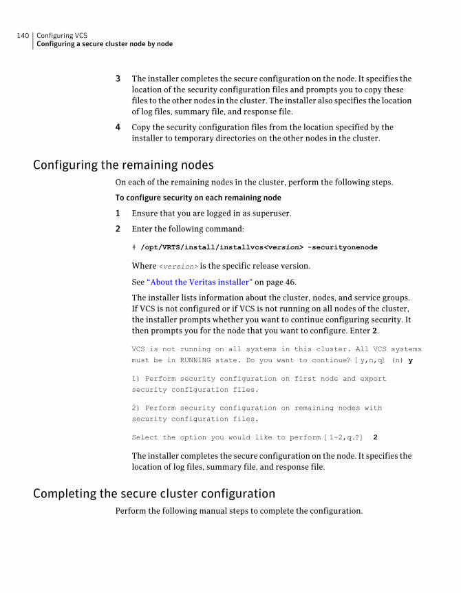
3 The installer completes the secure configuration on the node. It specifies thelocation of the security configuration files and prompts you to copy thesefiles to the other nodes in the cluster. The installer also specifies the locationof log files, summary file, and response file.
4 Copy the security configuration files from the location specified by theinstaller to temporary directories on the other nodes in the cluster.
Configuring the remaining nodesOn each of the remaining nodes in the cluster, perform the following steps.
To configure security on each remaining node
1 Ensure that you are logged in as superuser.
2 Enter the following command:
# /opt/VRTS/install/installvcs<version> -securityonenode
Where <version> is the specific release version.
See “About the Veritas installer” on page 46.
The installer lists information about the cluster, nodes, and service groups.If VCS is not configured or if VCS is not running on all nodes of the cluster,the installer prompts whether you want to continue configuring security. Itthen prompts you for the node that you want to configure. Enter 2.
VCS is not running on all systems in this cluster. All VCS systems
must be in RUNNING state. Do you want to continue? [y,n,q] (n) y
1) Perform security configuration on first node and export
security configuration files.
2) Perform security configuration on remaining nodes with
security configuration files.
Select the option you would like to perform [1-2,q.?] 2
The installer completes the secure configuration on the node. It specifies thelocation of log files, summary file, and response file.
Completing the secure cluster configurationPerform the following manual steps to complete the configuration.
Configuring VCSConfiguring a secure cluster node by node
140
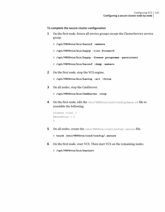
To complete the secure cluster configuration
1 On the first node, freeze all service groups except the ClusterService servicegroup.
# /opt/VRTSvcs/bin/haconf -makerw
# /opt/VRTSvcs/bin/hagrp -list Frozen=0
# /opt/VRTSvcs/bin/hagrp -freeze groupname -persistent
# /opt/VRTSvcs/bin/haconf -dump -makero
2 On the first node, stop the VCS engine.
# /opt/VRTSvcs/bin/hastop -all -force
3 On all nodes, stop the CmdServer.
# /opt/VRTSvcs/bin/CmdServer -stop
4 On the first node, edit the /etc/VRTSvcs/conf/config/main.cf file toresemble the following:
cluster clus1 (
SecureClus = 1
)
5 On all nodes, create the /etc/VRTSvcs/conf/config/.secure file.
# touch /etc/VRTSvcs/conf/config/.secure
6 On the first node, start VCS. Then start VCS on the remaining nodes.
# /opt/VRTSvcs/bin/hastart
141Configuring VCSConfiguring a secure cluster node by node
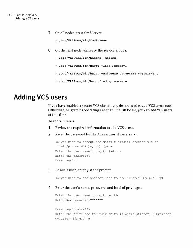
7 On all nodes, start CmdServer.
# /opt/VRTSvcs/bin/CmdServer
8 On the first node, unfreeze the service groups.
# /opt/VRTSvcs/bin/haconf -makerw
# /opt/VRTSvcs/bin/hagrp -list Frozen=1
# /opt/VRTSvcs/bin/hagrp -unfreeze groupname -persistent
# /opt/VRTSvcs/bin/haconf -dump -makero
Adding VCS usersIf you have enabled a secure VCS cluster, you do not need to add VCS users now.Otherwise, on systems operating under an English locale, you can add VCS usersat this time.
To add VCS users
1 Review the required information to add VCS users.
2 Reset the password for the Admin user, if necessary.
Do you wish to accept the default cluster credentials of
'admin/password'? [y,n,q] (y) n
Enter the user name: [b,q,?] (admin)
Enter the password:
Enter again:
3 To add a user, enter y at the prompt.
Do you want to add another user to the cluster? [y,n,q] (y)
4 Enter the user’s name, password, and level of privileges.
Enter the user name: [b,q,?] smith
Enter New Password:*******
Enter Again:*******
Enter the privilege for user smith (A=Administrator, O=Operator,
G=Guest): [b,q,?] a
Configuring VCSAdding VCS users
142
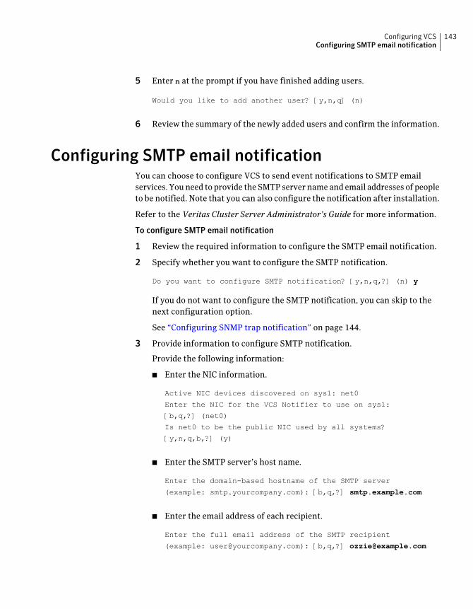
5 Enter n at the prompt if you have finished adding users.
Would you like to add another user? [y,n,q] (n)
6 Review the summary of the newly added users and confirm the information.
Configuring SMTP email notificationYou can choose to configure VCS to send event notifications to SMTP emailservices. You need to provide the SMTP server name and email addresses of peopleto be notified. Note that you can also configure the notification after installation.
Refer to the Veritas Cluster Server Administrator’s Guide for more information.
To configure SMTP email notification
1 Review the required information to configure the SMTP email notification.
2 Specify whether you want to configure the SMTP notification.
Do you want to configure SMTP notification? [y,n,q,?] (n) y
If you do not want to configure the SMTP notification, you can skip to thenext configuration option.
See “Configuring SNMP trap notification” on page 144.
3 Provide information to configure SMTP notification.
Provide the following information:
■ Enter the NIC information.
Active NIC devices discovered on sys1: net0
Enter the NIC for the VCS Notifier to use on sys1:
[b,q,?] (net0)
Is net0 to be the public NIC used by all systems?
[y,n,q,b,?] (y)
■ Enter the SMTP server’s host name.
Enter the domain-based hostname of the SMTP server
(example: smtp.yourcompany.com): [b,q,?] smtp.example.com
■ Enter the email address of each recipient.
Enter the full email address of the SMTP recipient
(example: [email protected]): [b,q,?] [email protected]
143Configuring VCSConfiguring SMTP email notification
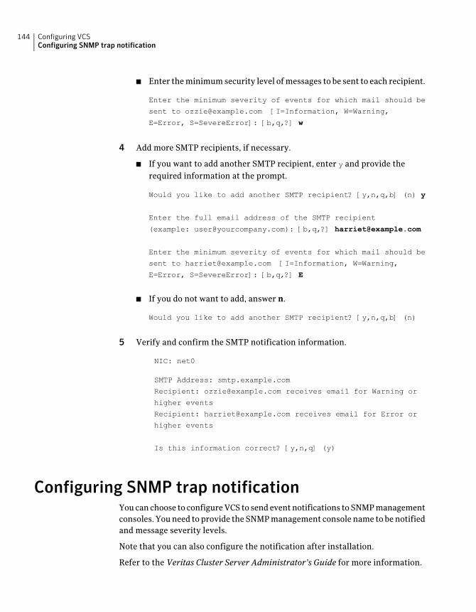
■ Enter the minimum security level of messages to be sent to each recipient.
Enter the minimum severity of events for which mail should be
sent to [email protected] [I=Information, W=Warning,
E=Error, S=SevereError]: [b,q,?] w
4 Add more SMTP recipients, if necessary.
■ If you want to add another SMTP recipient, enter y and provide therequired information at the prompt.
Would you like to add another SMTP recipient? [y,n,q,b] (n) y
Enter the full email address of the SMTP recipient
(example: [email protected]): [b,q,?] [email protected]
Enter the minimum severity of events for which mail should be
sent to [email protected] [I=Information, W=Warning,
E=Error, S=SevereError]: [b,q,?] E
■ If you do not want to add, answer n.
Would you like to add another SMTP recipient? [y,n,q,b] (n)
5 Verify and confirm the SMTP notification information.
NIC: net0
SMTP Address: smtp.example.com
Recipient: [email protected] receives email for Warning or
higher events
Recipient: [email protected] receives email for Error or
higher events
Is this information correct? [y,n,q] (y)
Configuring SNMP trap notificationYou can choose to configure VCS to send event notifications to SNMP managementconsoles. You need to provide the SNMP management console name to be notifiedand message severity levels.
Note that you can also configure the notification after installation.
Refer to the Veritas Cluster Server Administrator’s Guide for more information.
Configuring VCSConfiguring SNMP trap notification
144
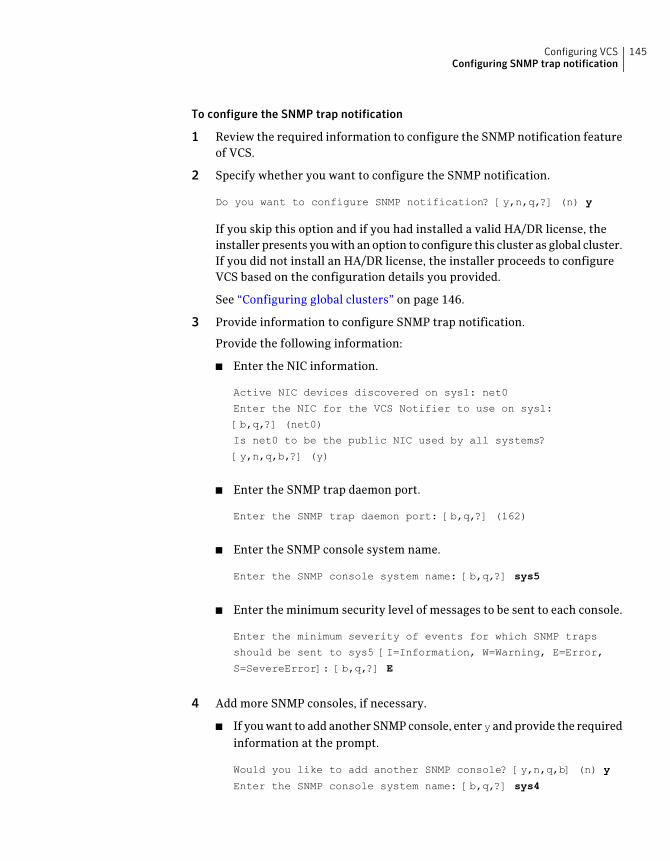
To configure the SNMP trap notification
1 Review the required information to configure the SNMP notification featureof VCS.
2 Specify whether you want to configure the SNMP notification.
Do you want to configure SNMP notification? [y,n,q,?] (n) y
If you skip this option and if you had installed a valid HA/DR license, theinstaller presents you with an option to configure this cluster as global cluster.If you did not install an HA/DR license, the installer proceeds to configureVCS based on the configuration details you provided.
See “Configuring global clusters” on page 146.
3 Provide information to configure SNMP trap notification.
Provide the following information:
■ Enter the NIC information.
Active NIC devices discovered on sys1: net0
Enter the NIC for the VCS Notifier to use on sys1:
[b,q,?] (net0)
Is net0 to be the public NIC used by all systems?
[y,n,q,b,?] (y)
■ Enter the SNMP trap daemon port.
Enter the SNMP trap daemon port: [b,q,?] (162)
■ Enter the SNMP console system name.
Enter the SNMP console system name: [b,q,?] sys5
■ Enter the minimum security level of messages to be sent to each console.
Enter the minimum severity of events for which SNMP traps
should be sent to sys5 [I=Information, W=Warning, E=Error,
S=SevereError]: [b,q,?] E
4 Add more SNMP consoles, if necessary.
■ If you want to add another SNMP console, enter y and provide the requiredinformation at the prompt.
Would you like to add another SNMP console? [y,n,q,b] (n) y
Enter the SNMP console system name: [b,q,?] sys4
145Configuring VCSConfiguring SNMP trap notification
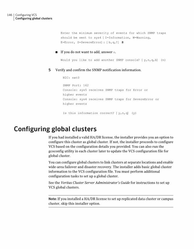
Enter the minimum severity of events for which SNMP traps
should be sent to sys4 [I=Information, W=Warning,
E=Error, S=SevereError]: [b,q,?] S
■ If you do not want to add, answer n.
Would you like to add another SNMP console? [y,n,q,b] (n)
5 Verify and confirm the SNMP notification information.
NIC: net0
SNMP Port: 162
Console: sys5 receives SNMP traps for Error or
higher events
Console: sys4 receives SNMP traps for SevereError or
higher events
Is this information correct? [y,n,q] (y)
Configuring global clustersIf you had installed a valid HA/DR license, the installer provides you an option toconfigure this cluster as global cluster. If not, the installer proceeds to configureVCS based on the configuration details you provided. You can also run thegcoconfig utility in each cluster later to update the VCS configuration file forglobal cluster.
You can configure global clusters to link clusters at separate locations and enablewide-area failover and disaster recovery. The installer adds basic global clusterinformation to the VCS configuration file. You must perform additionalconfiguration tasks to set up a global cluster.
See the Veritas Cluster Server Administrator’s Guide for instructions to set upVCS global clusters.
Note: If you installed a HA/DR license to set up replicated data cluster or campuscluster, skip this installer option.
Configuring VCSConfiguring global clusters
146
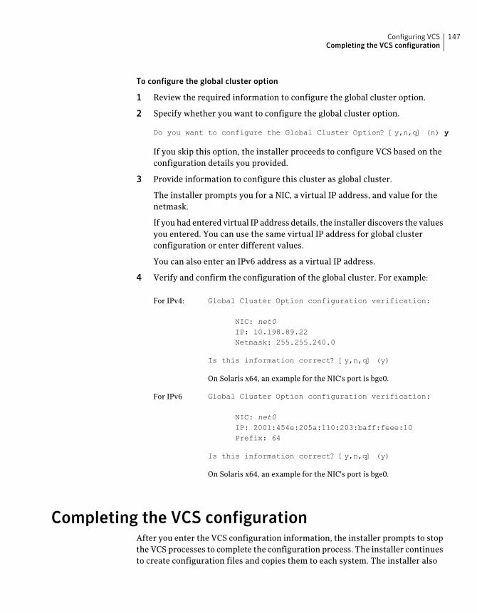
To configure the global cluster option
1 Review the required information to configure the global cluster option.
2 Specify whether you want to configure the global cluster option.
Do you want to configure the Global Cluster Option? [y,n,q] (n) y
If you skip this option, the installer proceeds to configure VCS based on theconfiguration details you provided.
3 Provide information to configure this cluster as global cluster.
The installer prompts you for a NIC, a virtual IP address, and value for thenetmask.
If you had entered virtual IP address details, the installer discovers the valuesyou entered. You can use the same virtual IP address for global clusterconfiguration or enter different values.
You can also enter an IPv6 address as a virtual IP address.
4 Verify and confirm the configuration of the global cluster. For example:
Global Cluster Option configuration verification:
NIC: net0IP: 10.198.89.22Netmask: 255.255.240.0
Is this information correct? [y,n,q] (y)
On Solaris x64, an example for the NIC's port is bge0.
For IPv4:
Global Cluster Option configuration verification:
NIC: net0IP: 2001:454e:205a:110:203:baff:feee:10Prefix: 64
Is this information correct? [y,n,q] (y)
On Solaris x64, an example for the NIC's port is bge0.
For IPv6
Completing the VCS configurationAfter you enter the VCS configuration information, the installer prompts to stopthe VCS processes to complete the configuration process. The installer continuesto create configuration files and copies them to each system. The installer also
147Configuring VCSCompleting the VCS configuration
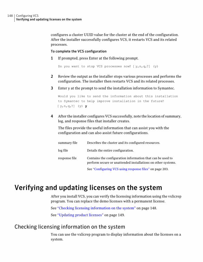
configures a cluster UUID value for the cluster at the end of the configuration.After the installer successfully configures VCS, it restarts VCS and its relatedprocesses.
To complete the VCS configuration
1 If prompted, press Enter at the following prompt.
Do you want to stop VCS processes now? [y,n,q,?] (y)
2 Review the output as the installer stops various processes and performs theconfiguration. The installer then restarts VCS and its related processes.
3 Enter y at the prompt to send the installation information to Symantec.
Would you like to send the information about this installation
to Symantec to help improve installation in the future?
[y,n,q,?] (y) y
4 After the installer configures VCS successfully, note the location of summary,log, and response files that installer creates.
The files provide the useful information that can assist you with theconfiguration and can also assist future configurations.
Describes the cluster and its configured resources.summary file
Details the entire configuration.log file
Contains the configuration information that can be used toperform secure or unattended installations on other systems.
See “Configuring VCS using response files” on page 203.
response file
Verifying and updating licenses on the systemAfter you install VCS, you can verify the licensing information using the vxlicrepprogram. You can replace the demo licenses with a permanent license.
See “Checking licensing information on the system” on page 148.
See “Updating product licenses” on page 149.
Checking licensing information on the systemYou can use the vxlicrep program to display information about the licenses on asystem.
Configuring VCSVerifying and updating licenses on the system
148
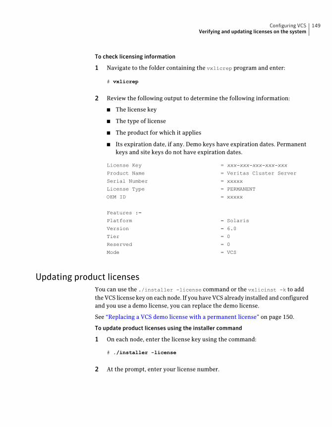
To check licensing information
1 Navigate to the folder containing the vxlicrep program and enter:
# vxlicrep
2 Review the following output to determine the following information:
■ The license key
■ The type of license
■ The product for which it applies
■ Its expiration date, if any. Demo keys have expiration dates. Permanentkeys and site keys do not have expiration dates.
License Key = xxx-xxx-xxx-xxx-xxx
Product Name = Veritas Cluster Server
Serial Number = xxxxx
License Type = PERMANENT
OEM ID = xxxxx
Features :=
Platform = Solaris
Version = 6.0
Tier = 0
Reserved = 0
Mode = VCS
Updating product licensesYou can use the ./installer -license command or the vxlicinst -k to addthe VCS license key on each node. If you have VCS already installed and configuredand you use a demo license, you can replace the demo license.
See “Replacing a VCS demo license with a permanent license” on page 150.
To update product licenses using the installer command
1 On each node, enter the license key using the command:
# ./installer -license
2 At the prompt, enter your license number.
149Configuring VCSVerifying and updating licenses on the system

To update product licenses using the vxlicinst command
◆ On each node, enter the license key using the command:
# vxlicinst -k license number
Replacing a VCS demo license with a permanent licenseWhen a VCS demo key license expires, you can replace it with a permanent licenseusing the vxlicinst(1) program.
To replace a demo key
1 Make sure you have permissions to log in as root on each of the nodes in thecluster.
2 Shut down VCS on all nodes in the cluster:
# hastop -all -force
This command does not shut down any running applications.
3 Enter the permanent license key using the following command on each node:
# vxlicinst -k license key
4 Make sure demo licenses are replaced on all cluster nodes before startingVCS.
# vxlicrep
5 Start VCS on each node:
# hastart
Configuring VCSVerifying and updating licenses on the system
150
Configuring VCS clustersfor data integrity
This chapter includes the following topics:
■ Setting up disk-based I/O fencing using installvcs program
■ Setting up server-based I/O fencing using installvcs program
■ Setting up non-SCSI-3 server-based I/O fencing in virtual environments usinginstallvcs program
■ Enabling or disabling the preferred fencing policy
Setting up disk-based I/O fencing using installvcsprogram
You can configure I/O fencing using the -fencingoption of the installvcs program.
Initializing disks as VxVM disksPerform the following procedure to initialize disks as VxVM disks.
To initialize disks as VxVM disks
1 List the new external disks or the LUNs as recognized by the operating system.On each node, enter:
# vxdisk list
2 To initialize the disks as VxVM disks, use one of the following methods:
■ Use the interactive vxdiskadm utility to initialize the disks as VxVM disks.
9Chapter
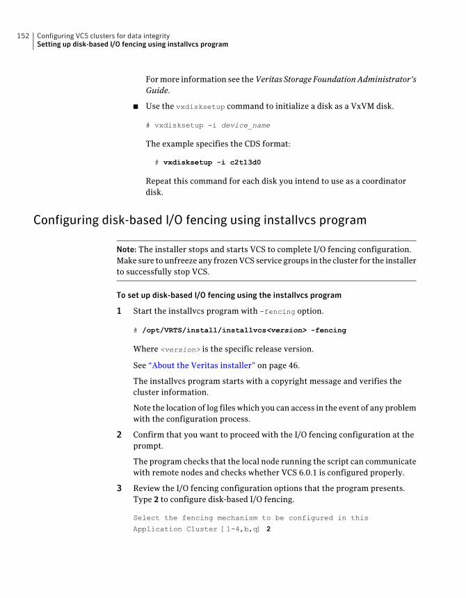
For more information see theVeritas Storage FoundationAdministrator’sGuide.
■ Use the vxdisksetup command to initialize a disk as a VxVM disk.
# vxdisksetup -i device_name
The example specifies the CDS format:
# vxdisksetup -i c2t13d0
Repeat this command for each disk you intend to use as a coordinatordisk.
Configuring disk-based I/O fencing using installvcs program
Note: The installer stops and starts VCS to complete I/O fencing configuration.Make sure to unfreeze any frozen VCS service groups in the cluster for the installerto successfully stop VCS.
To set up disk-based I/O fencing using the installvcs program
1 Start the installvcs program with -fencing option.
# /opt/VRTS/install/installvcs<version> -fencing
Where <version> is the specific release version.
See “About the Veritas installer” on page 46.
The installvcs program starts with a copyright message and verifies thecluster information.
Note the location of log files which you can access in the event of any problemwith the configuration process.
2 Confirm that you want to proceed with the I/O fencing configuration at theprompt.
The program checks that the local node running the script can communicatewith remote nodes and checks whether VCS 6.0.1 is configured properly.
3 Review the I/O fencing configuration options that the program presents.Type 2 to configure disk-based I/O fencing.
Select the fencing mechanism to be configured in this
Application Cluster [1-4,b,q] 2
Configuring VCS clusters for data integritySetting up disk-based I/O fencing using installvcs program
152
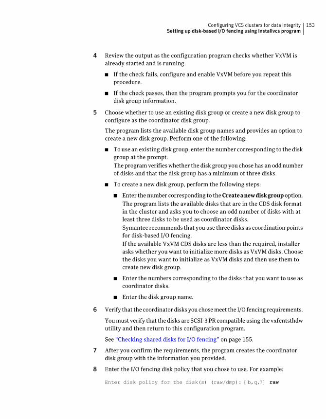
4 Review the output as the configuration program checks whether VxVM isalready started and is running.
■ If the check fails, configure and enable VxVM before you repeat thisprocedure.
■ If the check passes, then the program prompts you for the coordinatordisk group information.
5 Choose whether to use an existing disk group or create a new disk group toconfigure as the coordinator disk group.
The program lists the available disk group names and provides an option tocreate a new disk group. Perform one of the following:
■ To use an existing disk group, enter the number corresponding to the diskgroup at the prompt.The program verifies whether the disk group you chose has an odd numberof disks and that the disk group has a minimum of three disks.
■ To create a new disk group, perform the following steps:
■ Enter the number corresponding to the Createanewdiskgroup option.The program lists the available disks that are in the CDS disk formatin the cluster and asks you to choose an odd number of disks with atleast three disks to be used as coordinator disks.Symantec recommends that you use three disks as coordination pointsfor disk-based I/O fencing.If the available VxVM CDS disks are less than the required, installerasks whether you want to initialize more disks as VxVM disks. Choosethe disks you want to initialize as VxVM disks and then use them tocreate new disk group.
■ Enter the numbers corresponding to the disks that you want to use ascoordinator disks.
■ Enter the disk group name.
6 Verify that the coordinator disks you chose meet the I/O fencing requirements.
You must verify that the disks are SCSI-3 PR compatible using the vxfentsthdwutility and then return to this configuration program.
See “Checking shared disks for I/O fencing” on page 155.
7 After you confirm the requirements, the program creates the coordinatordisk group with the information you provided.
8 Enter the I/O fencing disk policy that you chose to use. For example:
Enter disk policy for the disk(s) (raw/dmp): [b,q,?] raw
153Configuring VCS clusters for data integritySetting up disk-based I/O fencing using installvcs program
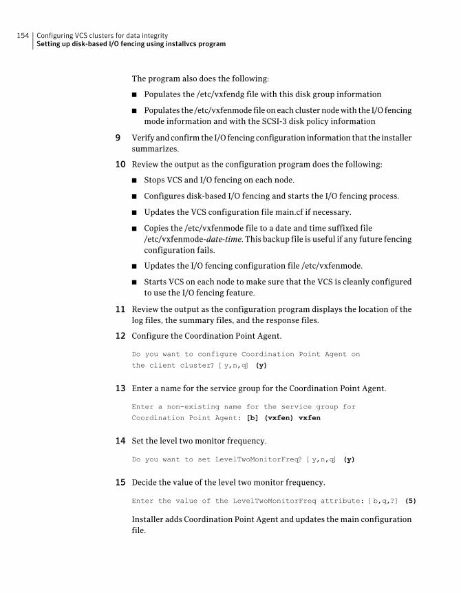
The program also does the following:
■ Populates the /etc/vxfendg file with this disk group information
■ Populates the /etc/vxfenmode file on each cluster node with the I/O fencingmode information and with the SCSI-3 disk policy information
9 Verify and confirm the I/O fencing configuration information that the installersummarizes.
10 Review the output as the configuration program does the following:
■ Stops VCS and I/O fencing on each node.
■ Configures disk-based I/O fencing and starts the I/O fencing process.
■ Updates the VCS configuration file main.cf if necessary.
■ Copies the /etc/vxfenmode file to a date and time suffixed file/etc/vxfenmode-date-time. This backup file is useful if any future fencingconfiguration fails.
■ Updates the I/O fencing configuration file /etc/vxfenmode.
■ Starts VCS on each node to make sure that the VCS is cleanly configuredto use the I/O fencing feature.
11 Review the output as the configuration program displays the location of thelog files, the summary files, and the response files.
12 Configure the Coordination Point Agent.
Do you want to configure Coordination Point Agent on
the client cluster? [y,n,q] (y)
13 Enter a name for the service group for the Coordination Point Agent.
Enter a non-existing name for the service group for
Coordination Point Agent: [b] (vxfen) vxfen
14 Set the level two monitor frequency.
Do you want to set LevelTwoMonitorFreq? [y,n,q] (y)
15 Decide the value of the level two monitor frequency.
Enter the value of the LevelTwoMonitorFreq attribute: [b,q,?] (5)
Installer adds Coordination Point Agent and updates the main configurationfile.
Configuring VCS clusters for data integritySetting up disk-based I/O fencing using installvcs program
154
See “Configuring CoordPoint agent to monitor coordination points” on page 278.
Checking shared disks for I/O fencingMake sure that the shared storage you set up while preparing to configure VCSmeets the I/O fencing requirements. You can test the shared disks using thevxfentsthdw utility. The two nodes must have ssh (default) or rsh communication.To confirm whether a disk (or LUN) supports SCSI-3 persistent reservations, twonodes must simultaneously have access to the same disks. Because a shared diskis likely to have a different name on each node, check the serial number to verifythe identity of the disk. Use the vxfenadm command with the -i option. Thiscommand option verifies that the same serial number for the LUN is returned onall paths to the LUN.
Make sure to test the disks that serve as coordinator disks.
The vxfentsthdw utility has additional options suitable for testing many disks.Review the options for testing the disk groups (-g) and the disks that are listedin a file (-f). You can also test disks without destroying data using the -r option.
See the Veritas Cluster Server Administrator's Guide.
Checking that disks support SCSI-3 involves the following tasks:
■ Verifying the Array Support Library (ASL)See “Verifying Array Support Library (ASL)” on page 155.
■ Verifying that nodes have access to the same diskSee “Verifying that the nodes have access to the same disk” on page 156.
■ Testing the shared disks for SCSI-3See “Testing the disks using vxfentsthdw utility” on page 157.
Verifying Array Support Library (ASL)Make sure that the Array Support Library (ASL) for the array that you add isinstalled.
155Configuring VCS clusters for data integritySetting up disk-based I/O fencing using installvcs program
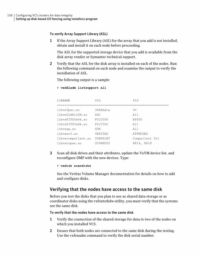
To verify Array Support Library (ASL)
1 If the Array Support Library (ASL) for the array that you add is not installed,obtain and install it on each node before proceeding.
The ASL for the supported storage device that you add is available from thedisk array vendor or Symantec technical support.
2 Verify that the ASL for the disk array is installed on each of the nodes. Runthe following command on each node and examine the output to verify theinstallation of ASL.
The following output is a sample:
# vxddladm listsupport all
LIBNAME VID PID
===========================================================
libvx3par.so 3PARdata VV
libvxCLARiiON.so DGC All
libvxFJTSYe6k.so FUJITSU E6000
libvxFJTSYe8k.so FUJITSU All
libvxap.so SUN All
libvxatf.so VERITAS ATFNODES
libvxcompellent.so COMPELNT Compellent Vol
libvxcopan.so COPANSYS 8814, 8818
3 Scan all disk drives and their attributes, update the VxVM device list, andreconfigure DMP with the new devices. Type:
# vxdisk scandisks
See the Veritas Volume Manager documentation for details on how to addand configure disks.
Verifying that the nodes have access to the same diskBefore you test the disks that you plan to use as shared data storage or ascoordinator disks using the vxfentsthdw utility, you must verify that the systemssee the same disk.
To verify that the nodes have access to the same disk
1 Verify the connection of the shared storage for data to two of the nodes onwhich you installed VCS.
2 Ensure that both nodes are connected to the same disk during the testing.Use the vxfenadm command to verify the disk serial number.
Configuring VCS clusters for data integritySetting up disk-based I/O fencing using installvcs program
156
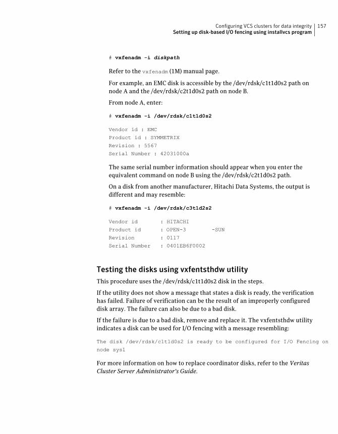
# vxfenadm -i diskpath
Refer to the vxfenadm (1M) manual page.
For example, an EMC disk is accessible by the /dev/rdsk/c1t1d0s2 path onnode A and the /dev/rdsk/c2t1d0s2 path on node B.
From node A, enter:
# vxfenadm -i /dev/rdsk/c1t1d0s2
Vendor id : EMC
Product id : SYMMETRIX
Revision : 5567
Serial Number : 42031000a
The same serial number information should appear when you enter theequivalent command on node B using the /dev/rdsk/c2t1d0s2 path.
On a disk from another manufacturer, Hitachi Data Systems, the output isdifferent and may resemble:
# vxfenadm -i /dev/rdsk/c3t1d2s2
Vendor id : HITACHI
Product id : OPEN-3 -SUN
Revision : 0117
Serial Number : 0401EB6F0002
Testing the disks using vxfentsthdw utilityThis procedure uses the /dev/rdsk/c1t1d0s2 disk in the steps.
If the utility does not show a message that states a disk is ready, the verificationhas failed. Failure of verification can be the result of an improperly configureddisk array. The failure can also be due to a bad disk.
If the failure is due to a bad disk, remove and replace it. The vxfentsthdw utilityindicates a disk can be used for I/O fencing with a message resembling:
The disk /dev/rdsk/c1t1d0s2 is ready to be configured for I/O Fencing on
node sys1
For more information on how to replace coordinator disks, refer to the VeritasCluster Server Administrator's Guide.
157Configuring VCS clusters for data integritySetting up disk-based I/O fencing using installvcs program
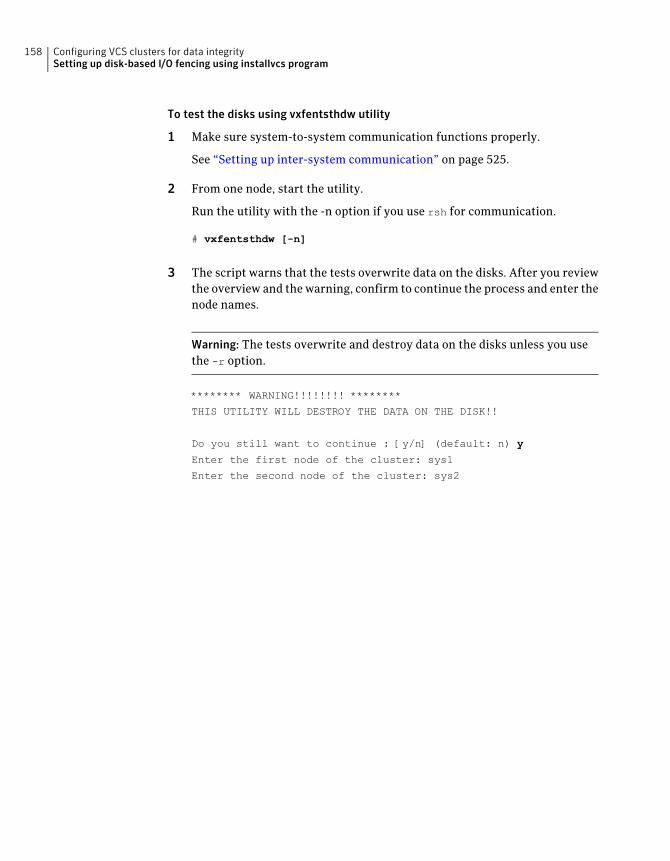
To test the disks using vxfentsthdw utility
1 Make sure system-to-system communication functions properly.
See “Setting up inter-system communication” on page 525.
2 From one node, start the utility.
Run the utility with the -n option if you use rsh for communication.
# vxfentsthdw [-n]
3 The script warns that the tests overwrite data on the disks. After you reviewthe overview and the warning, confirm to continue the process and enter thenode names.
Warning: The tests overwrite and destroy data on the disks unless you usethe -r option.
******** WARNING!!!!!!!! ********
THIS UTILITY WILL DESTROY THE DATA ON THE DISK!!
Do you still want to continue : [y/n] (default: n) y
Enter the first node of the cluster: sys1
Enter the second node of the cluster: sys2
Configuring VCS clusters for data integritySetting up disk-based I/O fencing using installvcs program
158
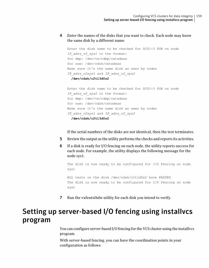
4 Enter the names of the disks that you want to check. Each node may knowthe same disk by a different name:
Enter the disk name to be checked for SCSI-3 PGR on node
IP_adrs_of_sys1 in the format:
for dmp: /dev/vx/rdmp/cxtxdxsx
for raw: /dev/rdsk/cxtxdxsx
Make sure it's the same disk as seen by nodes
IP_adrs_ofsys1 and IP_adrs_of_sys2
/dev/rdsk/c2t13d0s2
Enter the disk name to be checked for SCSI-3 PGR on node
IP_adrs_of_sys2 in the format:
for dmp: /dev/vx/rdmp/cxtxdxsx
for raw: /dev/rdsk/cxtxdxsx
Make sure it's the same disk as seen by nodes
IP_adrs_ofsys1 and IP_adrs_of_sys2
/dev/rdsk/c2t13d0s2
If the serial numbers of the disks are not identical, then the test terminates.
5 Review the output as the utility performs the checks and reports its activities.
6 If a disk is ready for I/O fencing on each node, the utility reports success foreach node. For example, the utility displays the following message for thenode sys1.
The disk is now ready to be configured for I/O Fencing on node
sys1
ALL tests on the disk /dev/rdsk/c1t1d0s2 have PASSED
The disk is now ready to be configured for I/O Fencing on node
sys1
7 Run the vxfentsthdw utility for each disk you intend to verify.
Setting up server-based I/O fencing using installvcsprogram
You can configure server-based I/O fencing for the VCS cluster using the installvcsprogram.
With server-based fencing, you can have the coordination points in yourconfiguration as follows:
159Configuring VCS clusters for data integritySetting up server-based I/O fencing using installvcs program
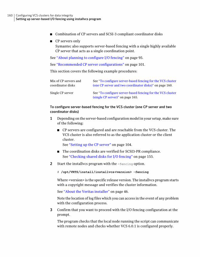
■ Combination of CP servers and SCSI-3 compliant coordinator disks
■ CP servers onlySymantec also supports server-based fencing with a single highly availableCP server that acts as a single coordination point.
See “About planning to configure I/O fencing” on page 95.
See “Recommended CP server configurations” on page 101.
This section covers the following example procedures:
See “To configure server-based fencing for the VCS cluster(one CP server and two coordinator disks)” on page 160.
Mix of CP servers andcoordinator disks
See “To configure server-based fencing for the VCS cluster(single CP server)” on page 165.
Single CP server
To configure server-based fencing for the VCS cluster (one CP server and twocoordinator disks)
1 Depending on the server-based configuration model in your setup, make sureof the following:
■ CP servers are configured and are reachable from the VCS cluster. TheVCS cluster is also referred to as the application cluster or the clientcluster.See “Setting up the CP server” on page 104.
■ The coordination disks are verified for SCSI3-PR compliance.See “Checking shared disks for I/O fencing” on page 155.
2 Start the installvcs program with the -fencing option.
# /opt/VRTS/install/installvcs<version> -fencing
Where <version> is the specific release version. The installvcs program startswith a copyright message and verifies the cluster information.
See “About the Veritas installer” on page 46.
Note the location of log files which you can access in the event of any problemwith the configuration process.
3 Confirm that you want to proceed with the I/O fencing configuration at theprompt.
The program checks that the local node running the script can communicatewith remote nodes and checks whether VCS 6.0.1 is configured properly.
Configuring VCS clusters for data integritySetting up server-based I/O fencing using installvcs program
160
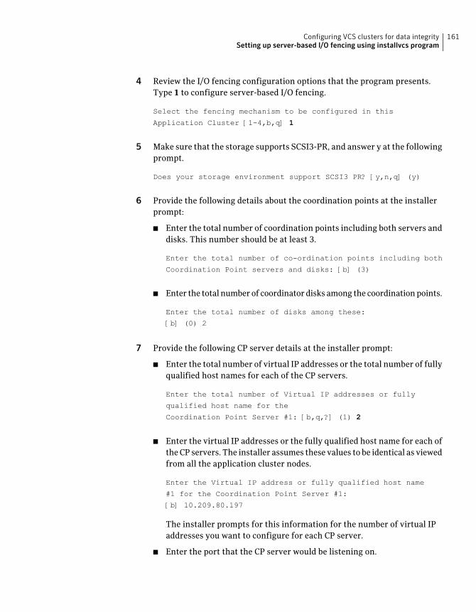
4 Review the I/O fencing configuration options that the program presents.Type 1 to configure server-based I/O fencing.
Select the fencing mechanism to be configured in this
Application Cluster [1-4,b,q] 1
5 Make sure that the storage supports SCSI3-PR, and answer y at the followingprompt.
Does your storage environment support SCSI3 PR? [y,n,q] (y)
6 Provide the following details about the coordination points at the installerprompt:
■ Enter the total number of coordination points including both servers anddisks. This number should be at least 3.
Enter the total number of co-ordination points including both
Coordination Point servers and disks: [b] (3)
■ Enter the total number of coordinator disks among the coordination points.
Enter the total number of disks among these:
[b] (0) 2
7 Provide the following CP server details at the installer prompt:
■ Enter the total number of virtual IP addresses or the total number of fullyqualified host names for each of the CP servers.
Enter the total number of Virtual IP addresses or fully
qualified host name for the
Coordination Point Server #1: [b,q,?] (1) 2
■ Enter the virtual IP addresses or the fully qualified host name for each ofthe CP servers. The installer assumes these values to be identical as viewedfrom all the application cluster nodes.
Enter the Virtual IP address or fully qualified host name
#1 for the Coordination Point Server #1:
[b] 10.209.80.197
The installer prompts for this information for the number of virtual IPaddresses you want to configure for each CP server.
■ Enter the port that the CP server would be listening on.
161Configuring VCS clusters for data integritySetting up server-based I/O fencing using installvcs program
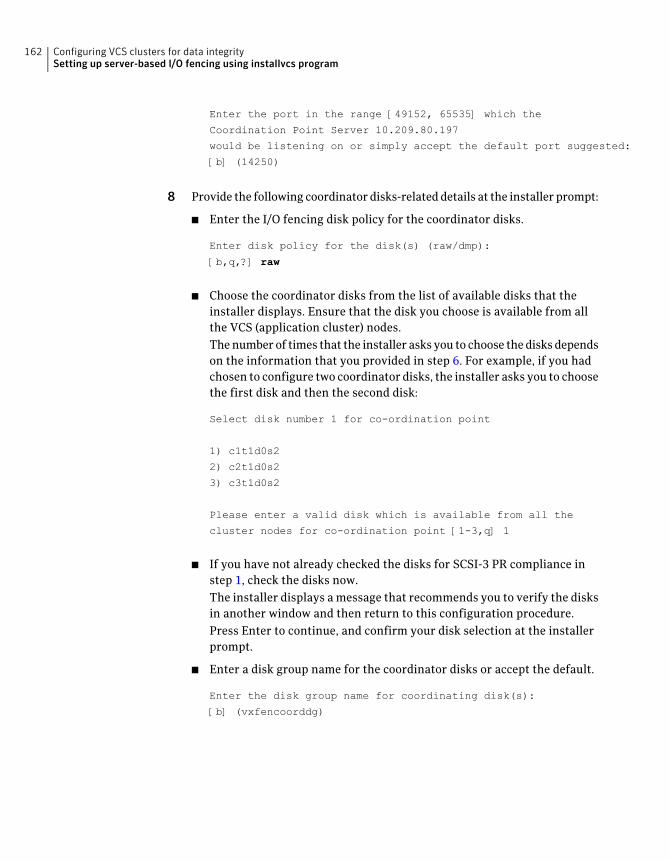
Enter the port in the range [49152, 65535] which the
Coordination Point Server 10.209.80.197
would be listening on or simply accept the default port suggested:
[b] (14250)
8 Provide the following coordinator disks-related details at the installer prompt:
■ Enter the I/O fencing disk policy for the coordinator disks.
Enter disk policy for the disk(s) (raw/dmp):
[b,q,?] raw
■ Choose the coordinator disks from the list of available disks that theinstaller displays. Ensure that the disk you choose is available from allthe VCS (application cluster) nodes.The number of times that the installer asks you to choose the disks dependson the information that you provided in step 6. For example, if you hadchosen to configure two coordinator disks, the installer asks you to choosethe first disk and then the second disk:
Select disk number 1 for co-ordination point
1) c1t1d0s2
2) c2t1d0s2
3) c3t1d0s2
Please enter a valid disk which is available from all the
cluster nodes for co-ordination point [1-3,q] 1
■ If you have not already checked the disks for SCSI-3 PR compliance instep 1, check the disks now.The installer displays a message that recommends you to verify the disksin another window and then return to this configuration procedure.Press Enter to continue, and confirm your disk selection at the installerprompt.
■ Enter a disk group name for the coordinator disks or accept the default.
Enter the disk group name for coordinating disk(s):
[b] (vxfencoorddg)
Configuring VCS clusters for data integritySetting up server-based I/O fencing using installvcs program
162
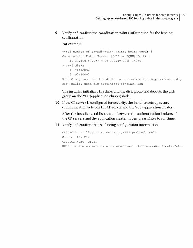
9 Verify and confirm the coordination points information for the fencingconfiguration.
For example:
Total number of coordination points being used: 3
Coordination Point Server ([VIP or FQHN]:Port):
1. 10.109.80.197 ([10.109.80.197]:14250)
SCSI-3 disks:
1. c1t1d0s2
2. c2t1d0s2
Disk Group name for the disks in customized fencing: vxfencoorddg
Disk policy used for customized fencing: raw
The installer initializes the disks and the disk group and deports the diskgroup on the VCS (application cluster) node.
10 If the CP server is configured for security, the installer sets up securecommunication between the CP server and the VCS (application cluster).
After the installer establishes trust between the authentication brokers ofthe CP servers and the application cluster nodes, press Enter to continue.
11 Verify and confirm the I/O fencing configuration information.
CPS Admin utility location: /opt/VRTScps/bin/cpsadm
Cluster ID: 2122
Cluster Name: clus1
UUID for the above cluster: {ae5e589a-1dd1-11b2-dd44-00144f79240c}
163Configuring VCS clusters for data integritySetting up server-based I/O fencing using installvcs program
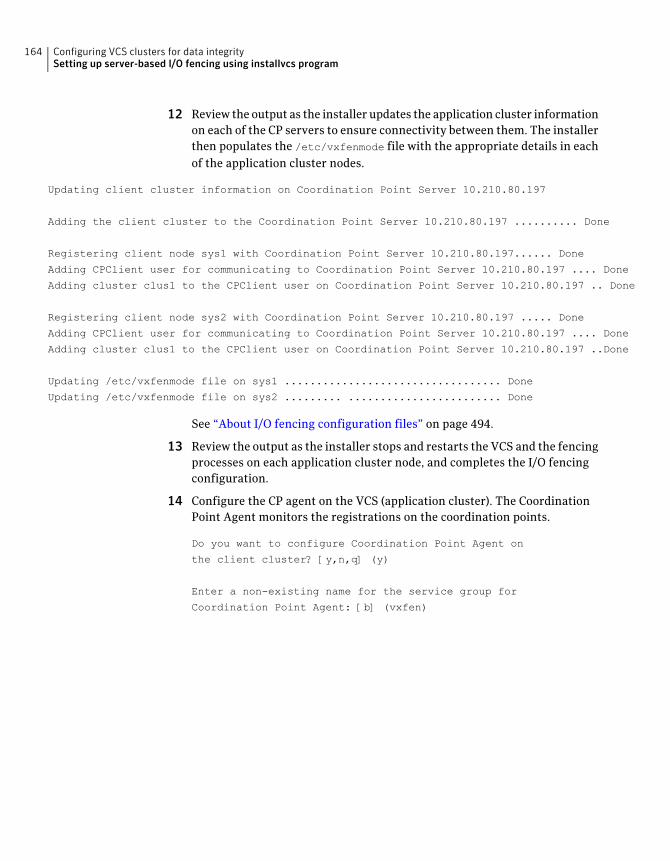
12 Review the output as the installer updates the application cluster informationon each of the CP servers to ensure connectivity between them. The installerthen populates the /etc/vxfenmode file with the appropriate details in eachof the application cluster nodes.
Updating client cluster information on Coordination Point Server 10.210.80.197
Adding the client cluster to the Coordination Point Server 10.210.80.197 .......... Done
Registering client node sys1 with Coordination Point Server 10.210.80.197...... Done
Adding CPClient user for communicating to Coordination Point Server 10.210.80.197 .... Done
Adding cluster clus1 to the CPClient user on Coordination Point Server 10.210.80.197 .. Done
Registering client node sys2 with Coordination Point Server 10.210.80.197 ..... Done
Adding CPClient user for communicating to Coordination Point Server 10.210.80.197 .... Done
Adding cluster clus1 to the CPClient user on Coordination Point Server 10.210.80.197 ..Done
Updating /etc/vxfenmode file on sys1 .................................. Done
Updating /etc/vxfenmode file on sys2 ......... ........................ Done
See “About I/O fencing configuration files” on page 494.
13 Review the output as the installer stops and restarts the VCS and the fencingprocesses on each application cluster node, and completes the I/O fencingconfiguration.
14 Configure the CP agent on the VCS (application cluster). The CoordinationPoint Agent monitors the registrations on the coordination points.
Do you want to configure Coordination Point Agent on
the client cluster? [y,n,q] (y)
Enter a non-existing name for the service group for
Coordination Point Agent: [b] (vxfen)
Configuring VCS clusters for data integritySetting up server-based I/O fencing using installvcs program
164
15 Additionally the coordination point agent can also monitor changes to theCoordinator Disk Group constitution such as a disk being accidently deletedfrom the Coordinator Disk Group. The frequency of this detailed monitoringcan be tuned with the LevelTwoMonitorFreq attribute. For example, if youset this attribute to 5, the agent will monitor the Coordinator Disk Groupconstitution every five monitor cycles.
Note that for the LevelTwoMonitorFreq attribute to be applicable there mustbe disks as part of the Coordinator Disk Group.
Enter the value of the LevelTwoMonitorFreq attribute: (5)
Adding Coordination Point Agent via sys1 .... Done
16 Note the location of the configuration log files, summary files, and responsefiles that the installer displays for later use.
To configure server-based fencing for the VCS cluster (single CP server)
1 Make sure that the CP server is configured and is reachable from the VCScluster. The VCS cluster is also referred to as the application cluster or theclient cluster.
2 See “Setting up the CP server” on page 104.
3 Start the installvcs program with -fencing option.
# /opt/VRTS/install/installvcs<version> -fencing
Where <version> is the specific release version. The installvcs program startswith a copyright message and verifies the cluster information.
See “About the Veritas installer” on page 46.
Note the location of log files which you can access in the event of any problemwith the configuration process.
4 Confirm that you want to proceed with the I/O fencing configuration at theprompt.
The program checks that the local node running the script can communicatewith remote nodes and checks whether VCS 6.0.1 is configured properly.
5 Review the I/O fencing configuration options that the program presents.Type 1 to configure server-based I/O fencing.
Select the fencing mechanism to be configured in this
Application Cluster [1-4,b,q] 1
165Configuring VCS clusters for data integritySetting up server-based I/O fencing using installvcs program
6 Make sure that the storage supports SCSI3-PR, and answer y at the followingprompt.
Does your storage environment support SCSI3 PR? [y,n,q] (y)
7 Enter the total number of coordination points as 1.
Enter the total number of co-ordination points including both
Coordination Point servers and disks: [b] (3) 1
Read the installer warning carefully before you proceed with the configuration.
8 Provide the following CP server details at the installer prompt:
■ Enter the total number of virtual IP addresses or the total numner of fullyqualified host names for each of the CP servers.
Enter the total number of Virtual IP addresses or fully
qualified host name for the
Coordination Point Server #1: [b,q,?] (1) 2
■ Enter the virtual IP address or the fully qualified host name for the CPserver. The installer assumes these values to be identical as viewed fromall the application cluster nodes.
Enter the Virtual IP address or fully qualified host name
#1 for the Coordination Point Server #1:
[b] 10.209.80.197
The installer prompts for this information for the number of virtual IPaddresses you want to configure for each CP server.
■ Enter the port that the CP server would be listening on.
Enter the port in the range [49152, 65535] which the
Coordination Point Server 10.209.80.197
would be listening on or simply accept the default
port suggested: [b] (14250)
9 Verify and confirm the coordination points information for the fencingconfiguration.
For example:
Total number of coordination points being used: 1
Coordination Point Server ([VIP or FQHN]:Port):
1. 10.109.80.197 ([10.109.80.197]:14250)
Configuring VCS clusters for data integritySetting up server-based I/O fencing using installvcs program
166
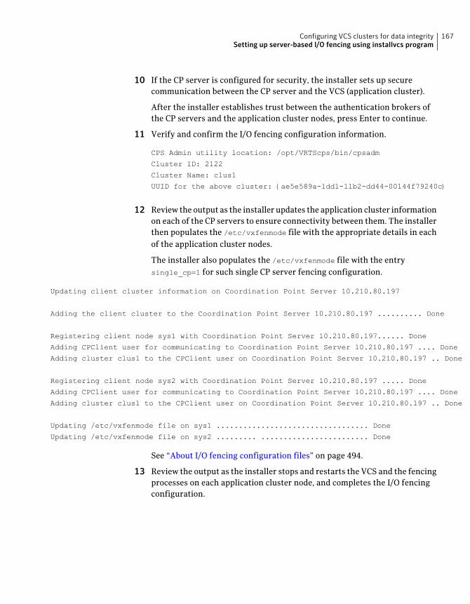
10 If the CP server is configured for security, the installer sets up securecommunication between the CP server and the VCS (application cluster).
After the installer establishes trust between the authentication brokers ofthe CP servers and the application cluster nodes, press Enter to continue.
11 Verify and confirm the I/O fencing configuration information.
CPS Admin utility location: /opt/VRTScps/bin/cpsadm
Cluster ID: 2122
Cluster Name: clus1
UUID for the above cluster: {ae5e589a-1dd1-11b2-dd44-00144f79240c}
12 Review the output as the installer updates the application cluster informationon each of the CP servers to ensure connectivity between them. The installerthen populates the /etc/vxfenmode file with the appropriate details in eachof the application cluster nodes.
The installer also populates the /etc/vxfenmode file with the entrysingle_cp=1 for such single CP server fencing configuration.
Updating client cluster information on Coordination Point Server 10.210.80.197
Adding the client cluster to the Coordination Point Server 10.210.80.197 .......... Done
Registering client node sys1 with Coordination Point Server 10.210.80.197...... Done
Adding CPClient user for communicating to Coordination Point Server 10.210.80.197 .... Done
Adding cluster clus1 to the CPClient user on Coordination Point Server 10.210.80.197 .. Done
Registering client node sys2 with Coordination Point Server 10.210.80.197 ..... Done
Adding CPClient user for communicating to Coordination Point Server 10.210.80.197 .... Done
Adding cluster clus1 to the CPClient user on Coordination Point Server 10.210.80.197 .. Done
Updating /etc/vxfenmode file on sys1 .................................. Done
Updating /etc/vxfenmode file on sys2 ......... ........................ Done
See “About I/O fencing configuration files” on page 494.
13 Review the output as the installer stops and restarts the VCS and the fencingprocesses on each application cluster node, and completes the I/O fencingconfiguration.
167Configuring VCS clusters for data integritySetting up server-based I/O fencing using installvcs program
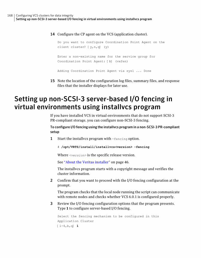
14 Configure the CP agent on the VCS (application cluster).
Do you want to configure Coordination Point Agent on the
client cluster? [y,n,q] (y)
Enter a non-existing name for the service group for
Coordination Point Agent: [b] (vxfen)
Adding Coordination Point Agent via sys1 ... Done
15 Note the location of the configuration log files, summary files, and responsefiles that the installer displays for later use.
Setting up non-SCSI-3 server-based I/O fencing invirtual environments using installvcs program
If you have installed VCS in virtual environments that do not support SCSI-3PR-compliant storage, you can configure non-SCSI-3 fencing.
To configure I/O fencing using the installvcs program in a non-SCSI-3 PR-compliantsetup
1 Start the installvcs program with -fencing option.
# /opt/VRTS/install/installvcs<version> -fencing
Where <version> is the specific release version.
See “About the Veritas installer” on page 46.
The installvcs program starts with a copyright message and verifies thecluster information.
2 Confirm that you want to proceed with the I/O fencing configuration at theprompt.
The program checks that the local node running the script can communicatewith remote nodes and checks whether VCS 6.0.1 is configured properly.
3 Review the I/O fencing configuration options that the program presents.Type 1 to configure server-based I/O fencing.
Select the fencing mechanism to be configured in this
Application Cluster
[1-4,b,q] 1
Configuring VCS clusters for data integritySetting up non-SCSI-3 server-based I/O fencing in virtual environments using installvcs program
168
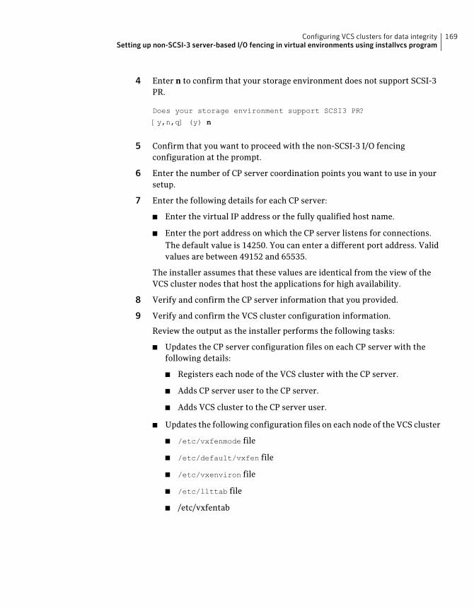
4 Enter n to confirm that your storage environment does not support SCSI-3PR.
Does your storage environment support SCSI3 PR?
[y,n,q] (y) n
5 Confirm that you want to proceed with the non-SCSI-3 I/O fencingconfiguration at the prompt.
6 Enter the number of CP server coordination points you want to use in yoursetup.
7 Enter the following details for each CP server:
■ Enter the virtual IP address or the fully qualified host name.
■ Enter the port address on which the CP server listens for connections.The default value is 14250. You can enter a different port address. Validvalues are between 49152 and 65535.
The installer assumes that these values are identical from the view of theVCS cluster nodes that host the applications for high availability.
8 Verify and confirm the CP server information that you provided.
9 Verify and confirm the VCS cluster configuration information.
Review the output as the installer performs the following tasks:
■ Updates the CP server configuration files on each CP server with thefollowing details:
■ Registers each node of the VCS cluster with the CP server.
■ Adds CP server user to the CP server.
■ Adds VCS cluster to the CP server user.
■ Updates the following configuration files on each node of the VCS cluster
■ /etc/vxfenmode file
■ /etc/default/vxfen file
■ /etc/vxenviron file
■ /etc/llttab file
■ /etc/vxfentab
169Configuring VCS clusters for data integritySetting up non-SCSI-3 server-based I/O fencing in virtual environments using installvcs program

10 Review the output as the installer stops VCS on each node, starts I/O fencingon each node, updates the VCS configuration file main.cf, and restarts VCSwith non-SCSI-3 server-based fencing.
Confirm to configure the CP agent on the VCS cluster.
11 Confirm whether you want to send the installation information to Symantec.
12 After the installer configures I/O fencing successfully, note the location ofsummary, log, and response files that installer creates.
The files provide useful information which can assist you with theconfiguration, and can also assist future configurations.
Enabling or disabling the preferred fencing policyYou can enable or disable the preferred fencing feature for your I/O fencingconfiguration.
You can enable preferred fencing to use system-based race policy or group-basedrace policy. If you disable preferred fencing, the I/O fencing configuration usesthe default count-based race policy.
See “About preferred fencing” on page 33.
To enable preferred fencing for the I/O fencing configuration
1 Make sure that the cluster is running with I/O fencing set up.
# vxfenadm -d
2 Make sure that the cluster-level attribute UseFence has the value set to SCSI3.
# haclus -value UseFence
3 To enable system-based race policy, perform the following steps:
■ Make the VCS configuration writable.
# haconf -makerw
■ Set the value of the cluster-level attribute PreferredFencingPolicy asSystem.
# haclus -modify PreferredFencingPolicy System
■ Set the value of the system-level attribute FencingWeight for each nodein the cluster.
Configuring VCS clusters for data integrityEnabling or disabling the preferred fencing policy
170
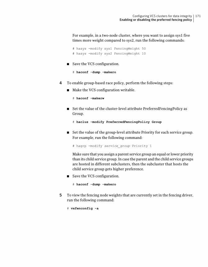
For example, in a two-node cluster, where you want to assign sys1 fivetimes more weight compared to sys2, run the following commands:
# hasys -modify sys1 FencingWeight 50
# hasys -modify sys2 FencingWeight 10
■ Save the VCS configuration.
# haconf -dump -makero
4 To enable group-based race policy, perform the following steps:
■ Make the VCS configuration writable.
# haconf -makerw
■ Set the value of the cluster-level attribute PreferredFencingPolicy asGroup.
# haclus -modify PreferredFencingPolicy Group
■ Set the value of the group-level attribute Priority for each service group.For example, run the following command:
# hagrp -modify service_group Priority 1
Make sure that you assign a parent service group an equal or lower prioritythan its child service group. In case the parent and the child service groupsare hosted in different subclusters, then the subcluster that hosts thechild service group gets higher preference.
■ Save the VCS configuration.
# haconf -dump -makero
5 To view the fencing node weights that are currently set in the fencing driver,run the following command:
# vxfenconfig -a
171Configuring VCS clusters for data integrityEnabling or disabling the preferred fencing policy
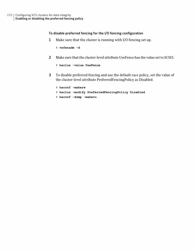
To disable preferred fencing for the I/O fencing configuration
1 Make sure that the cluster is running with I/O fencing set up.
# vxfenadm -d
2 Make sure that the cluster-level attribute UseFence has the value set to SCSI3.
# haclus -value UseFence
3 To disable preferred fencing and use the default race policy, set the value ofthe cluster-level attribute PreferredFencingPolicy as Disabled.
# haconf -makerw
# haclus -modify PreferredFencingPolicy Disabled
# haconf -dump -makero
Configuring VCS clusters for data integrityEnabling or disabling the preferred fencing policy
172
Installation using theWeb-based installer
■ Chapter 10. Installing VCS
■ Chapter 11. Configuring VCS
4Section

174
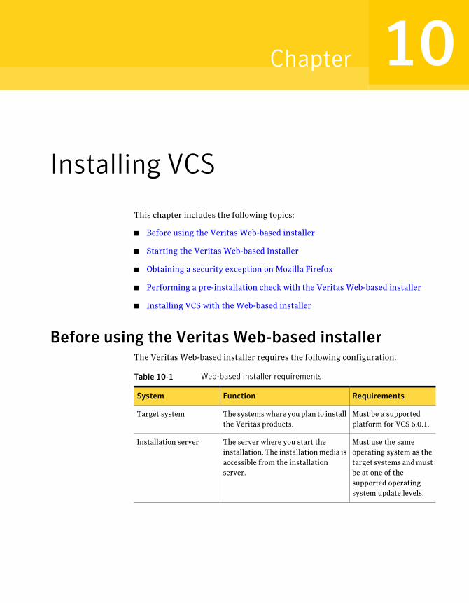
Installing VCS
This chapter includes the following topics:
■ Before using the Veritas Web-based installer
■ Starting the Veritas Web-based installer
■ Obtaining a security exception on Mozilla Firefox
■ Performing a pre-installation check with the Veritas Web-based installer
■ Installing VCS with the Web-based installer
Before using the Veritas Web-based installerThe Veritas Web-based installer requires the following configuration.
Table 10-1 Web-based installer requirements
RequirementsFunctionSystem
Must be a supportedplatform for VCS 6.0.1.
The systems where you plan to installthe Veritas products.
Target system
Must use the sameoperating system as thetarget systems and mustbe at one of thesupported operatingsystem update levels.
The server where you start theinstallation. The installation media isaccessible from the installationserver.
Installation server
10Chapter
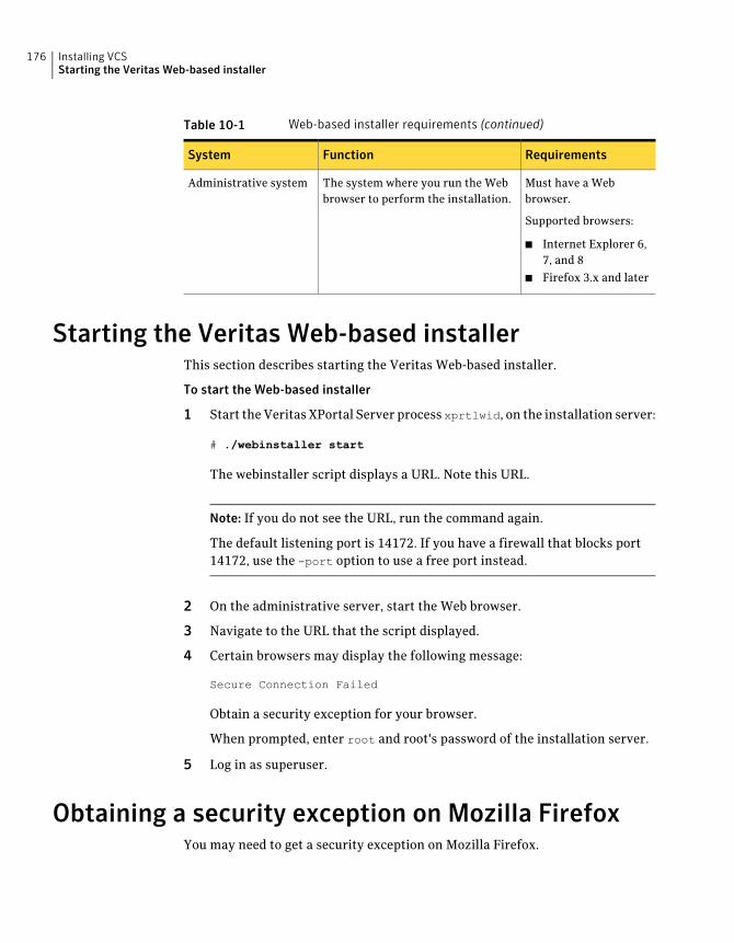
Table 10-1 Web-based installer requirements (continued)
RequirementsFunctionSystem
Must have a Webbrowser.
Supported browsers:
■ Internet Explorer 6,7, and 8
■ Firefox 3.x and later
The system where you run the Webbrowser to perform the installation.
Administrative system
Starting the Veritas Web-based installerThis section describes starting the Veritas Web-based installer.
To start the Web-based installer
1 Start the Veritas XPortal Server process xprtlwid, on the installation server:
# ./webinstaller start
The webinstaller script displays a URL. Note this URL.
Note: If you do not see the URL, run the command again.
The default listening port is 14172. If you have a firewall that blocks port14172, use the -port option to use a free port instead.
2 On the administrative server, start the Web browser.
3 Navigate to the URL that the script displayed.
4 Certain browsers may display the following message:
Secure Connection Failed
Obtain a security exception for your browser.
When prompted, enter root and root's password of the installation server.
5 Log in as superuser.
Obtaining a security exception on Mozilla FirefoxYou may need to get a security exception on Mozilla Firefox.
Installing VCSStarting the Veritas Web-based installer
176
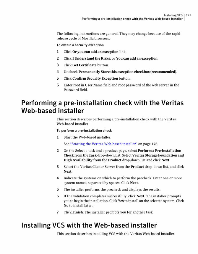
The following instructions are general. They may change because of the rapidrelease cycle of Mozilla browsers.
To obtain a security exception
1 Click Or you can add an exception link.
2 Click I Understand the Risks, or You can add an exception.
3 Click Get Certificate button.
4 Uncheck Permanently Store this exception checkbox (recommended).
5 Click Confirm Security Exception button.
6 Enter root in User Name field and root password of the web server in thePassword field.
Performing a pre-installation check with the VeritasWeb-based installer
This section describes performing a pre-installation check with the VeritasWeb-based installer.
To perform a pre-installation check
1 Start the Web-based installer.
See “Starting the Veritas Web-based installer” on page 176.
2 On the Select a task and a product page, select Perform a Pre-installationCheck from the Task drop-down list. Select VeritasStorageFoundationandHigh Availability from the Product drop-down list and click Next.
3 Select the Veritas Cluster Server from the Product drop-down list, and clickNext.
4 Indicate the systems on which to perform the precheck. Enter one or moresystem names, separated by spaces. Click Next.
5 The installer performs the precheck and displays the results.
6 If the validation completes successfully, click Next. The installer promptsyou to begin the installation. Click Yes to install on the selected system. ClickNo to install later.
7 Click Finish. The installer prompts you for another task.
Installing VCS with the Web-based installerThis section describes installing VCS with the Veritas Web-based installer.
177Installing VCSPerforming a pre-installation check with the Veritas Web-based installer
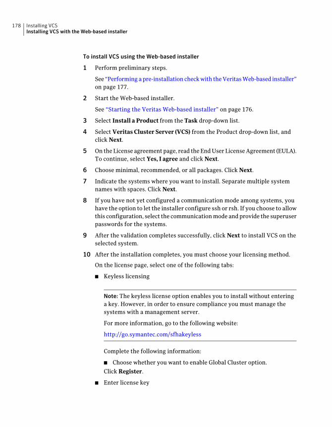
To install VCS using the Web-based installer
1 Perform preliminary steps.
See “Performing a pre-installation check with the Veritas Web-based installer”on page 177.
2 Start the Web-based installer.
See “Starting the Veritas Web-based installer” on page 176.
3 Select Install a Product from the Task drop-down list.
4 Select Veritas Cluster Server (VCS) from the Product drop-down list, andclick Next.
5 On the License agreement page, read the End User License Agreement (EULA).To continue, select Yes, I agree and click Next.
6 Choose minimal, recommended, or all packages. Click Next.
7 Indicate the systems where you want to install. Separate multiple systemnames with spaces. Click Next.
8 If you have not yet configured a communication mode among systems, youhave the option to let the installer configure ssh or rsh. If you choose to allowthis configuration, select the communication mode and provide the superuserpasswords for the systems.
9 After the validation completes successfully, click Next to install VCS on theselected system.
10 After the installation completes, you must choose your licensing method.
On the license page, select one of the following tabs:
■ Keyless licensing
Note: The keyless license option enables you to install without enteringa key. However, in order to ensure compliance you must manage thesystems with a management server.
For more information, go to the following website:
http://go.symantec.com/sfhakeyless
Complete the following information:
■ Choose whether you want to enable Global Cluster option.
Click Register.
■ Enter license key
Installing VCSInstalling VCS with the Web-based installer
178

If you have a valid license key, select this tab. Enter the license key foreach system. Click Register.
11 The installer prompts you to configure the cluster. Select Yes to continuewith configuring the product.
If you select No, you can exit the installer. You must configure the productbefore you can use VCS.
After the installation completes, the installer displays the location of the logand summary files. If required, view the files to confirm the installation status.
12 If prompted, select the checkbox to specify whether you want to send yourinstallation information to Symantec.
Would you like to send the information about this installation
to Symantec to help improve installation in the future?
Click Finish. The installer asks if you would like to read the summary file.Select Yes to read the summary file. If you select No, the installer promptsyou for another task.
179Installing VCSInstalling VCS with the Web-based installer

Installing VCSInstalling VCS with the Web-based installer
180
Configuring VCS
This chapter includes the following topics:
■ Configuring VCS using the Web-based installer
Configuring VCS using the Web-based installerBefore you begin to configure VCS using the Web-based installer, review theconfiguration requirements.
See “Getting your VCS installation and configuration information ready”on page 78.
By default, the communication between the systems is selected as SSH. If SSH isused for communication between systems, the SSH commands execute withoutprompting for passwords or confirmations.
You can click Quit to quit the Web-installer at any time during the configurationprocess.
To configure VCS on a cluster
1 Start the Web-based installer.
See “Starting the Veritas Web-based installer” on page 176.
2 On the Select a task and a product page, select the task and the product asfollows:
Configure a ProductTask
Veritas Cluster ServerProduct
Click Next.
11Chapter
3 On the Select Systems page, enter the system names where you want toconfigure VCS, and click Next.
Example: sys1 sys2
The installer performs the initial system verification. It checks for the systemcommunication. It also checks for release compatibility, installed productversion, platform version, and performs product prechecks.
Click Next after the installer completes the system verification successfully.
4 In the Confirmation dialog box that appears, choose whether or not toconfigure I/O fencing.
To configure I/O fencing, click Yes.
To configure I/O fencing later, click No. You can configure I/O fencing laterusing the Web-based installer.
See “Configuring VCS for data integrity using the Web-based installer”on page 186.
You can also configure I/O fencing later using the installvcs<version>
-fencing command, the response files, or manually configure.
Where <version> is the specific release version.
See “About the Veritas installer” on page 46.
Configuring VCSConfiguring VCS using the Web-based installer
182
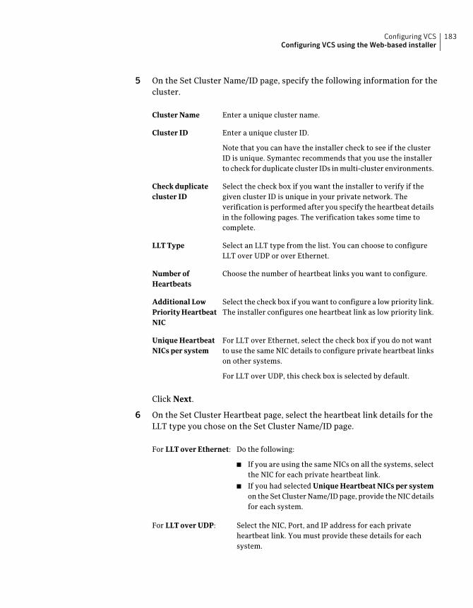
5 On the Set Cluster Name/ID page, specify the following information for thecluster.
Enter a unique cluster name.Cluster Name
Enter a unique cluster ID.
Note that you can have the installer check to see if the clusterID is unique. Symantec recommends that you use the installerto check for duplicate cluster IDs in multi-cluster environments.
Cluster ID
Select the check box if you want the installer to verify if thegiven cluster ID is unique in your private network. Theverification is performed after you specify the heartbeat detailsin the following pages. The verification takes some time tocomplete.
Check duplicatecluster ID
Select an LLT type from the list. You can choose to configureLLT over UDP or over Ethernet.
LLT Type
Choose the number of heartbeat links you want to configure.Number ofHeartbeats
Select the check box if you want to configure a low priority link.The installer configures one heartbeat link as low priority link.
Additional LowPriorityHeartbeatNIC
For LLT over Ethernet, select the check box if you do not wantto use the same NIC details to configure private heartbeat linkson other systems.
For LLT over UDP, this check box is selected by default.
Unique HeartbeatNICs per system
Click Next.
6 On the Set Cluster Heartbeat page, select the heartbeat link details for theLLT type you chose on the Set Cluster Name/ID page.
Do the following:
■ If you are using the same NICs on all the systems, selectthe NIC for each private heartbeat link.
■ If you had selected Unique Heartbeat NICs per systemon the Set Cluster Name/ID page, provide the NIC detailsfor each system.
For LLT over Ethernet:
Select the NIC, Port, and IP address for each privateheartbeat link. You must provide these details for eachsystem.
For LLT over UDP:
183Configuring VCSConfiguring VCS using the Web-based installer
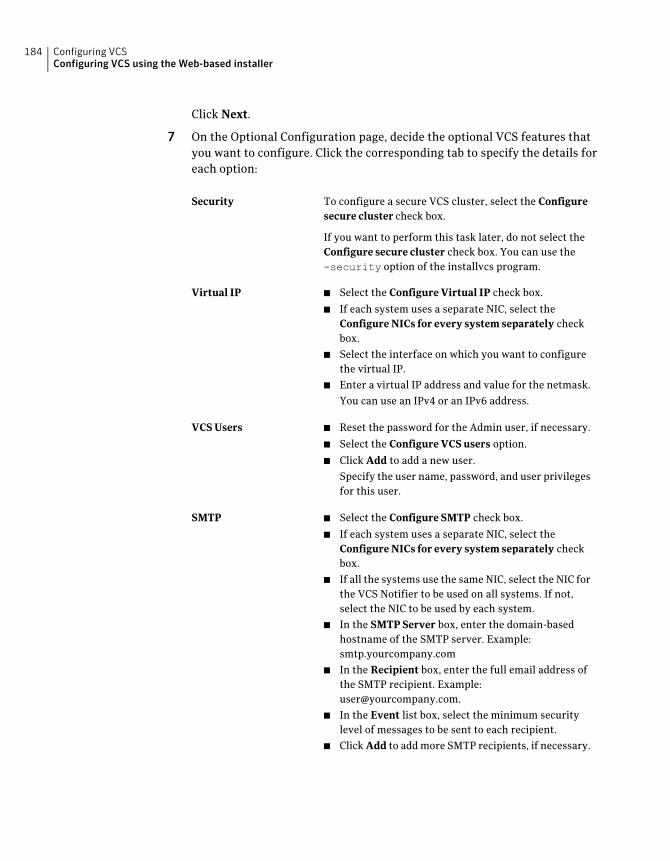
Click Next.
7 On the Optional Configuration page, decide the optional VCS features thatyou want to configure. Click the corresponding tab to specify the details foreach option:
To configure a secure VCS cluster, select the Configuresecure cluster check box.
If you want to perform this task later, do not select theConfigure secure cluster check box. You can use the-security option of the installvcs program.
Security
■ Select the Configure Virtual IP check box.
■ If each system uses a separate NIC, select theConfigure NICs for every system separately checkbox.
■ Select the interface on which you want to configurethe virtual IP.
■ Enter a virtual IP address and value for the netmask.
You can use an IPv4 or an IPv6 address.
Virtual IP
■ Reset the password for the Admin user, if necessary.
■ Select the Configure VCS users option.
■ Click Add to add a new user.
Specify the user name, password, and user privilegesfor this user.
VCS Users
■ Select the Configure SMTP check box.
■ If each system uses a separate NIC, select theConfigure NICs for every system separately checkbox.
■ If all the systems use the same NIC, select the NIC forthe VCS Notifier to be used on all systems. If not,select the NIC to be used by each system.
■ In the SMTP Server box, enter the domain-basedhostname of the SMTP server. Example:smtp.yourcompany.com
■ In the Recipient box, enter the full email address ofthe SMTP recipient. Example:[email protected].
■ In the Event list box, select the minimum securitylevel of messages to be sent to each recipient.
■ Click Add to add more SMTP recipients, if necessary.
SMTP
Configuring VCSConfiguring VCS using the Web-based installer
184
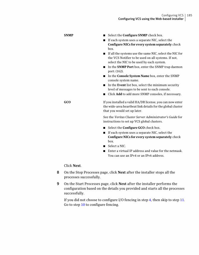
■ Select the Configure SNMP check box.
■ If each system uses a separate NIC, select theConfigure NICs for every system separately checkbox.
■ If all the systems use the same NIC, select the NIC forthe VCS Notifier to be used on all systems. If not,select the NIC to be used by each system.
■ In the SNMP Port box, enter the SNMP trap daemonport: (162).
■ In the Console System Name box, enter the SNMPconsole system name.
■ In the Event list box, select the minimum securitylevel of messages to be sent to each console.
■ Click Add to add more SNMP consoles, if necessary.
SNMP
If you installed a valid HA/DR license, you can now enterthe wide-area heartbeat link details for the global clusterthat you would set up later.
See the Veritas Cluster Server Administrator's Guide forinstructions to set up VCS global clusters.
■ Select the Configure GCO check box.
■ If each system uses a separate NIC, select theConfigure NICs for every system separately checkbox.
■ Select a NIC.
■ Enter a virtual IP address and value for the netmask.
You can use an IPv4 or an IPv6 address.
GCO
Click Next.
8 On the Stop Processes page, click Next after the installer stops all theprocesses successfully.
9 On the Start Processes page, click Next after the installer performs theconfiguration based on the details you provided and starts all the processessuccessfully.
If you did not choose to configure I/O fencing in step 4, then skip to step 11.Go to step 10 to configure fencing.
185Configuring VCSConfiguring VCS using the Web-based installer
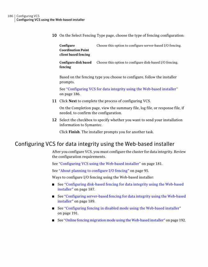
10 On the Select Fencing Type page, choose the type of fencing configuration:
Choose this option to configure server-based I/O fencing.ConfigureCoordination Pointclient based fencing
Choose this option to configure disk-based I/O fencing.Configure disk basedfencing
Based on the fencing type you choose to configure, follow the installerprompts.
See “Configuring VCS for data integrity using the Web-based installer”on page 186.
11 Click Next to complete the process of configuring VCS.
On the Completion page, view the summary file, log file, or response file, ifneeded, to confirm the configuration.
12 Select the checkbox to specify whether you want to send your installationinformation to Symantec.
Click Finish. The installer prompts you for another task.
Configuring VCS for data integrity using the Web-based installerAfter you configure VCS, you must configure the cluster for data integrity. Reviewthe configuration requirements.
See “Configuring VCS using the Web-based installer” on page 181.
See “About planning to configure I/O fencing” on page 95.
Ways to configure I/O fencing using the Web-based installer:
■ See “Configuring disk-based fencing for data integrity using the Web-basedinstaller” on page 187.
■ See “Configuring server-based fencing for data integrity using the Web-basedinstaller” on page 189.
■ See “Configuring fencing in disabled mode using the Web-based installer”on page 191.
■ See “Online fencing migration mode using the Web-based installer” on page 192.
Configuring VCSConfiguring VCS using the Web-based installer
186
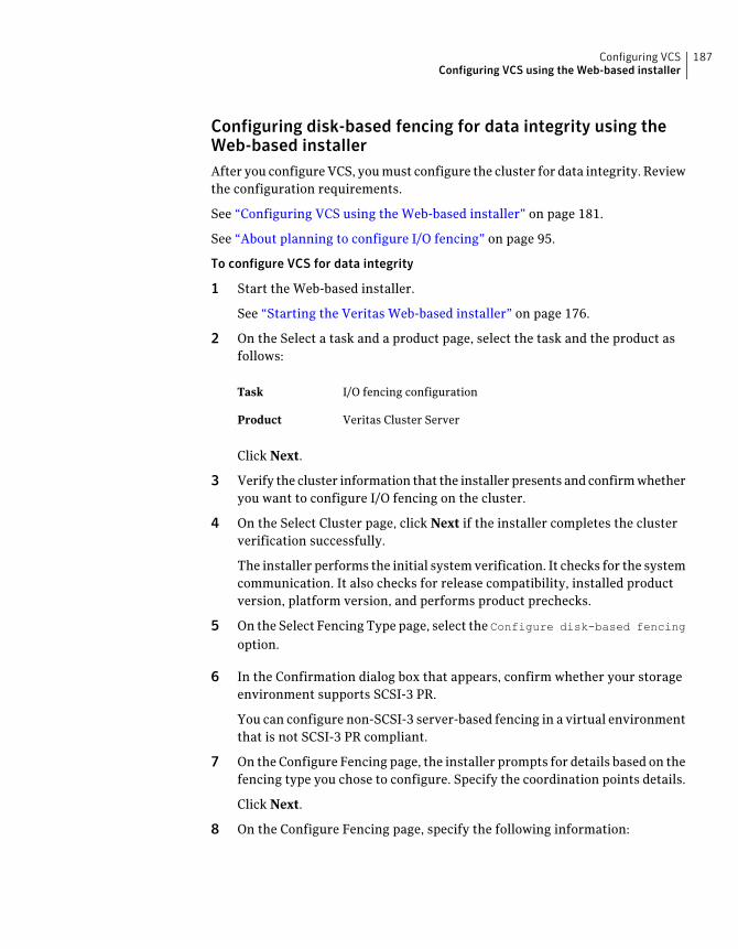
Configuring disk-based fencing for data integrity using theWeb-based installerAfter you configure VCS, you must configure the cluster for data integrity. Reviewthe configuration requirements.
See “Configuring VCS using the Web-based installer” on page 181.
See “About planning to configure I/O fencing” on page 95.
To configure VCS for data integrity
1 Start the Web-based installer.
See “Starting the Veritas Web-based installer” on page 176.
2 On the Select a task and a product page, select the task and the product asfollows:
I/O fencing configurationTask
Veritas Cluster ServerProduct
Click Next.
3 Verify the cluster information that the installer presents and confirm whetheryou want to configure I/O fencing on the cluster.
4 On the Select Cluster page, click Next if the installer completes the clusterverification successfully.
The installer performs the initial system verification. It checks for the systemcommunication. It also checks for release compatibility, installed productversion, platform version, and performs product prechecks.
5 On the Select Fencing Type page, select the Configure disk-based fencing
option.
6 In the Confirmation dialog box that appears, confirm whether your storageenvironment supports SCSI-3 PR.
You can configure non-SCSI-3 server-based fencing in a virtual environmentthat is not SCSI-3 PR compliant.
7 On the Configure Fencing page, the installer prompts for details based on thefencing type you chose to configure. Specify the coordination points details.
Click Next.
8 On the Configure Fencing page, specify the following information:
187Configuring VCSConfiguring VCS using the Web-based installer

Select the Create a new disk group option or select one ofthe disk groups from the list.
■ If you selected one of the disk groups that is listed,choose the fencing disk policy for the disk group.
■ If you selected the Createanewdiskgroup option, makesure you have SCSI-3 PR enabled disks, and click Yes inthe confirmation dialog box.
Click Next.
Select a Disk Group
9 On the Create New DG page, specify the following information:
Enter a name for the new coordinator disk group you wantto create.
New Disk Group Name
Select at least three disks to create the coordinator diskgroup.
If you want to select more than three disks, make sure toselect an odd number of disks.
Select Disks
Choose the fencing disk policy for the disk group.Fencing Disk Policy
10 If you want to configure the Coordination Point agent on the client cluster,do the following:
■ At the prompt for configuring the Coordination Point agent on the clientcluster, click Yes and enter the Coordination Point agent service groupname.
■ If you want to set the LevelTwoMonitorFreq attribute, click Yes at theprompt and enter a value (0 to 65535).
■ Follow the rest of the prompts to complete the Coordination Point agentconfiguration.
11 Click Next to complete the process of configuring I/O fencing.
On the Completion page, view the summary file, log file, or response file, ifneeded, to confirm the configuration.
12 Select the checkbox to specify whether you want to send your installationinformation to Symantec.
Click Finish. The installer prompts you for another task.
Configuring VCSConfiguring VCS using the Web-based installer
188
Configuring server-based fencing for data integrity using theWeb-based installerAfter you configure VCS, you must configure the cluster for data integrity. Reviewthe configuration requirements.
See “Configuring VCS using the Web-based installer” on page 181.
See “About planning to configure I/O fencing” on page 95.
To configure VCS for data integrity
1 Start the Web-based installer.
See “Starting the Veritas Web-based installer” on page 176.
2 On the Select a task and a product page, select the task and the product asfollows:
I/O fencing configurationTask
Veritas Cluster ServerProduct
Click Next.
3 Verify the cluster information that the installer presents and confirm whetheryou want to configure I/O fencing on the cluster.
4 On the Select Cluster page, click Next if the installer completes the clusterverification successfully.
The installer performs the initial system verification. It checks for the systemcommunication. It also checks for release compatibility, installed productversion, platform version, and performs product prechecks.
5 On the Select Fencing Type page, select theConfigure server-based fencing
option.
6 In the Confirmation dialog box that appears, confirm whether your storageenvironment supports SCSI-3 PR.
You can configure non-SCSI-3 server-based fencing in a virtual environmentthat is not SCSI-3 PR compliant.
7 On the Configure Fencing page, the installer prompts for details based on thefencing type you chose to configure. Specify the coordination points details.
Click Next.
8 Provide the following details for each of the CP servers:
189Configuring VCSConfiguring VCS using the Web-based installer
■ Enter the virtual IP addresses or host names of the virtual IP address. Theinstaller assumes these values to be identical as viewed from all theapplication cluster nodes.
■ Enter the port that the CP server must listen on.
■ Click Next.
9 If your server-based fencing configuration also uses disks as coordinationpoints, perform the following steps:
■ If you have not already checked the disks for SCSI-3 PR compliance, checkthe disks now, and click OK in the dialog box.
■ If you do not want to use the default coordinator disk group name, entera name for the new coordinator disk group you want to create.
■ Select the disks to create the coordinator disk group.
■ Choose the fencing disk policy for the disk group.The default fencing disk policy for the disk group is dmp.
10 In the Confirmation dialog box that appears, confirm whether the coordinationpoints information you provided is correct, and click Yes.
11 Verify and confirm the I/O fencing configuration information.
The installer stops and restarts the VCS and the fencing processes on eachapplication cluster node, and completes the I/O fencing configuration.
12 If you want to configure the Coordination Point agent on the client cluster,do the following:
■ At the prompt for configuring the Coordination Point agent on the clientcluster, click Yes and enter the Coordination Point agent service groupname.
■ Follow the rest of the prompts to complete the Coordination Point agentconfiguration.
13 Click Next to complete the process of configuring I/O fencing.
On the Completion page, view the summary file, log file, or response file, ifneeded, to confirm the configuration.
14 Select the checkbox to specify whether you want to send your installationinformation to Symantec.
Click Finish. The installer prompts you for another task.
Configuring VCSConfiguring VCS using the Web-based installer
190
Configuring fencing in disabled mode using the Web-basedinstallerAfter you configure VCS, you must configure the cluster for data integrity. Reviewthe configuration requirements.
See “Configuring VCS using the Web-based installer” on page 181.
See “About planning to configure I/O fencing” on page 95.
To configure VCS for data integrity
1 Start the Web-based installer.
See “Starting the Veritas Web-based installer” on page 176.
2 On the Select a task and a product page, select the task and the product asfollows:
I/O fencing configurationTask
Veritas Cluster ServerProduct
Click Next.
3 Verify the cluster information that the installer presents and confirm whetheryou want to configure I/O fencing on the cluster.
4 On the Select Cluster page, click Next if the installer completes the clusterverification successfully.
The installer performs the initial system verification. It checks for the systemcommunication. It also checks for release compatibility, installed productversion, platform version, and performs product prechecks.
5 Fencing may be enabled, installer may prompt whether you want toreconfigure it.
Click Yes.
6 On the Select Fencing Type page, select the Configure fencing in disabled
mode option.
7 Installer stops VCS before applying the selected fencing mode to the cluster.
Note: Unfreeze any frozen service group and unmount any file system thatis mounted in the cluster.
Click Yes.
8 Installer restarts VCS on all systems of the cluster. I/O fencing is disabled.
191Configuring VCSConfiguring VCS using the Web-based installer
9 Verify and confirm the I/O fencing configuration information.
On the Completion page, view the summary file, log file, or response file, ifneeded, to confirm the configuration.
10 Select the checkbox to specify whether you want to send your installationinformation to Symantec.
Click Finish. The installer prompts you for another task.
Online fencing migration mode using the Web-based installerAfter you configure VCS, you must configure the cluster for data integrity. Reviewthe configuration requirements.
See “Configuring VCS using the Web-based installer” on page 181.
See “About planning to configure I/O fencing” on page 95.
To configure VCS for data integrity
1 Start the Web-based installer.
See “Starting the Veritas Web-based installer” on page 176.
2 On the Select a task and a product page, select the task and the product asfollows:
I/O fencing configurationTask
Veritas Cluster ServerProduct
Click Next.
3 Verify the cluster information that the installer presents and confirm whetheryou want to configure I/O fencing on the cluster.
4 On the Select Cluster page, click Next if the installer completes the clusterverification successfully.
The installer performs the initial system verification. It checks for the systemcommunication. It also checks for release compatibility, installed productversion, platform version, and performs product prechecks.
5 Fencing may be enabled, installer may prompt whether you want toreconfigure it.
Click Yes.
6 On the Select Fencing Type page, select the Online fencing migration
option.
Configuring VCSConfiguring VCS using the Web-based installer
192
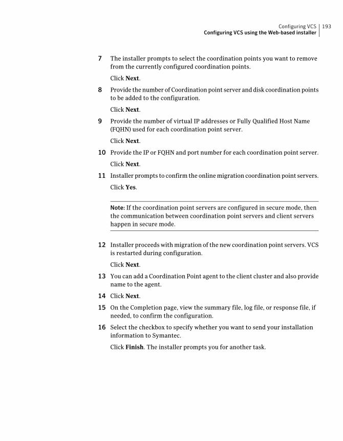
7 The installer prompts to select the coordination points you want to removefrom the currently configured coordination points.
Click Next.
8 Provide the number of Coordination point server and disk coordination pointsto be added to the configuration.
Click Next.
9 Provide the number of virtual IP addresses or Fully Qualified Host Name(FQHN) used for each coordination point server.
Click Next.
10 Provide the IP or FQHN and port number for each coordination point server.
Click Next.
11 Installer prompts to confirm the online migration coordination point servers.
Click Yes.
Note: If the coordination point servers are configured in secure mode, thenthe communication between coordination point servers and client servershappen in secure mode.
12 Installer proceeds with migration of the new coordination point servers. VCSis restarted during configuration.
Click Next.
13 You can add a Coordination Point agent to the client cluster and also providename to the agent.
14 Click Next.
15 On the Completion page, view the summary file, log file, or response file, ifneeded, to confirm the configuration.
16 Select the checkbox to specify whether you want to send your installationinformation to Symantec.
Click Finish. The installer prompts you for another task.
193Configuring VCSConfiguring VCS using the Web-based installer

Configuring VCSConfiguring VCS using the Web-based installer
194
Automated installation usingresponse files
■ Chapter 12. Performing an automated VCS installation
■ Chapter 13. Performing an automated VCS configuration
■ Chapter 14. Performing an automated I/O fencing configuration using responsefiles
5Section

196
Performing an automatedVCS installation
This chapter includes the following topics:
■ Installing VCS using response files
■ Response file variables to install VCS
■ Sample response file for installing VCS
Installing VCS using response filesTypically, you can use the response file that the installer generates after youperform VCS installation on one cluster to install VCS on other clusters. You canalso create a response file using the -makeresponsefile option of the installer.
To install VCS using response files
1 Make sure the systems where you want to install VCS meet the installationrequirements.
See “Important preinstallation information for VCS” on page 35.
2 Make sure the preinstallation tasks are completed.
See “Performing preinstallation tasks” on page 63.
3 Copy the response file to one of the cluster systems where you want to installVCS.
See “Sample response file for installing VCS” on page 200.
4 Edit the values of the response file variables as necessary.
See “Response file variables to install VCS” on page 198.
12Chapter
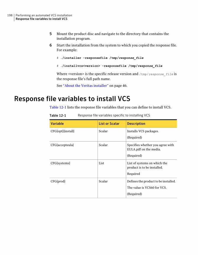
5 Mount the product disc and navigate to the directory that contains theinstallation program.
6 Start the installation from the system to which you copied the response file.For example:
# ./installer -responsefile /tmp/response_file
# ./installvcs<version> -responsefile /tmp/response_file
Where <version> is the specific release version and /tmp/response_file isthe response file’s full path name.
See “About the Veritas installer” on page 46.
Response file variables to install VCSTable 12-1 lists the response file variables that you can define to install VCS.
Table 12-1 Response file variables specific to installing VCS
DescriptionList or ScalarVariable
Installs VCS packages.
(Required)
ScalarCFG{opt}{install}
Specifies whether you agree withEULA.pdf on the media.
(Required)
ScalarCFG{accepteula}
List of systems on which theproduct is to be installed.
Required
ListCFG{systems}
Defines the product to be installed.
The value is VCS60 for VCS.
(Required)
ScalarCFG{prod}
Performing an automated VCS installationResponse file variables to install VCS
198
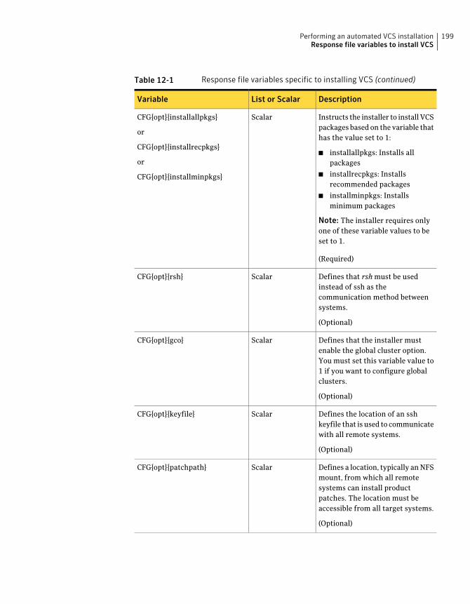
Table 12-1 Response file variables specific to installing VCS (continued)
DescriptionList or ScalarVariable
Instructs the installer to install VCSpackages based on the variable thathas the value set to 1:
■ installallpkgs: Installs allpackages
■ installrecpkgs: Installsrecommended packages
■ installminpkgs: Installsminimum packages
Note: The installer requires onlyone of these variable values to beset to 1.
(Required)
ScalarCFG{opt}{installallpkgs}
or
CFG{opt}{installrecpkgs}
or
CFG{opt}{installminpkgs}
Defines that rsh must be usedinstead of ssh as thecommunication method betweensystems.
(Optional)
ScalarCFG{opt}{rsh}
Defines that the installer mustenable the global cluster option.You must set this variable value to1 if you want to configure globalclusters.
(Optional)
ScalarCFG{opt}{gco}
Defines the location of an sshkeyfile that is used to communicatewith all remote systems.
(Optional)
ScalarCFG{opt}{keyfile}
Defines a location, typically an NFSmount, from which all remotesystems can install productpatches. The location must beaccessible from all target systems.
(Optional)
ScalarCFG{opt}{patchpath}
199Performing an automated VCS installationResponse file variables to install VCS
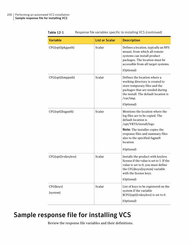
Table 12-1 Response file variables specific to installing VCS (continued)
DescriptionList or ScalarVariable
Defines a location, typically an NFSmount, from which all remotesystems can install productpackages. The location must beaccessible from all target systems.
(Optional)
ScalarCFG{opt}{pkgpath}
Defines the location where aworking directory is created tostore temporary files and thepackages that are needed duringthe install. The default location is/var/tmp.
(Optional)
ScalarCFG{opt}{tmppath}
Mentions the location where thelog files are to be copied. Thedefault location is/opt/VRTS/install/logs.
Note: The installer copies theresponse files and summary filesalso to the specified logpathlocation.
(Optional)
ScalarCFG{opt}{logpath}
Installs the product with keylesslicense if the value is set to 1. If thevalue is set to 0, you must definethe CFG{keys}{system} variablewith the license keys.
(Optional)
ScalarCFG{opt}{vxkeyless}
List of keys to be registered on thesystem if the variable$CFG{opt}{vxkeyless} is set to 0.
(Optional)
ScalarCFG{keys}
{system}
Sample response file for installing VCSReview the response file variables and their definitions.
Performing an automated VCS installationSample response file for installing VCS
200
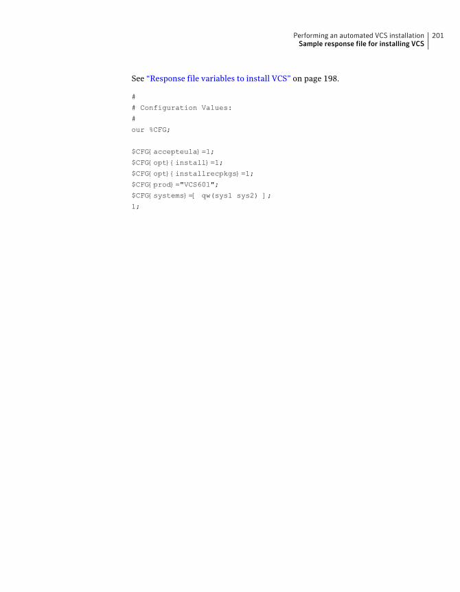
See “Response file variables to install VCS” on page 198.
#
# Configuration Values:
#
our %CFG;
$CFG{accepteula}=1;
$CFG{opt}{install}=1;
$CFG{opt}{installrecpkgs}=1;
$CFG{prod}="VCS601";
$CFG{systems}=[ qw(sys1 sys2) ];
1;
201Performing an automated VCS installationSample response file for installing VCS

Performing an automated VCS installationSample response file for installing VCS
202
Performing an automatedVCS configuration
This chapter includes the following topics:
■ Configuring VCS using response files
■ Response file variables to configure Veritas Cluster Server
■ Sample response file for configuring VCS
Configuring VCS using response filesTypically, you can use the response file that the installer generates after youperform VCS configuration on one cluster to configure VCS on other clusters. Youcan also create a response file using the -makeresponsefileoption of the installer.
To configure VCS using response files
1 Make sure the VCS packages are installed on the systems where you want toconfigure VCS.
2 Copy the response file to one of the cluster systems where you want toconfigure VCS.
See “Sample response file for configuring VCS” on page 213.
13Chapter
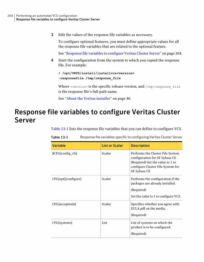
3 Edit the values of the response file variables as necessary.
To configure optional features, you must define appropriate values for allthe response file variables that are related to the optional feature.
See “Response file variables to configure Veritas Cluster Server” on page 204.
4 Start the configuration from the system to which you copied the responsefile. For example:
# /opt/VRTS/install/installvcs<version>
-responsefile /tmp/response_file
Where <version> is the specific release version, and /tmp/response_file
is the response file’s full path name.
See “About the Veritas installer” on page 46.
Response file variables to configure Veritas ClusterServer
Table 13-1 lists the response file variables that you can define to configure VCS.
Table 13-1 Response file variables specific to configuring Veritas Cluster Server
DescriptionList or ScalarVariable
Performs the Cluster File Systemconfiguration for SF Sybase CE(Required) Set the value to 1 toconfigure Cluster File System forSF Sybase CE
Scalar$CFG{config_cfs}
Performs the configuration if thepackages are already installed.
(Required)
Set the value to 1 to configure VCS.
ScalarCFG{opt}{configure}
Specifies whether you agree withEULA.pdf on the media.
(Required)
ScalarCFG{accepteula}
List of systems on which theproduct is to be configured.
(Required)
ListCFG{systems}
Performing an automated VCS configurationResponse file variables to configure Veritas Cluster Server
204
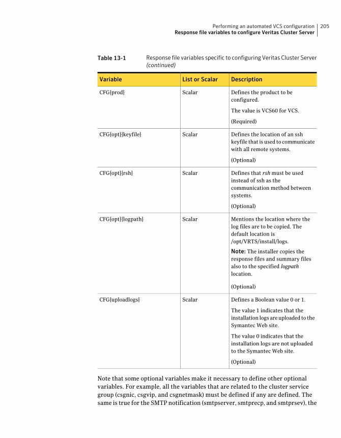
Table 13-1 Response file variables specific to configuring Veritas Cluster Server(continued)
DescriptionList or ScalarVariable
Defines the product to beconfigured.
The value is VCS60 for VCS.
(Required)
ScalarCFG{prod}
Defines the location of an sshkeyfile that is used to communicatewith all remote systems.
(Optional)
ScalarCFG{opt}{keyfile}
Defines that rsh must be usedinstead of ssh as thecommunication method betweensystems.
(Optional)
ScalarCFG{opt}{rsh}
Mentions the location where thelog files are to be copied. Thedefault location is/opt/VRTS/install/logs.
Note: The installer copies theresponse files and summary filesalso to the specified logpathlocation.
(Optional)
ScalarCFG{opt}{logpath}
Defines a Boolean value 0 or 1.
The value 1 indicates that theinstallation logs are uploaded to theSymantec Web site.
The value 0 indicates that theinstallation logs are not uploadedto the Symantec Web site.
(Optional)
ScalarCFG{uploadlogs}
Note that some optional variables make it necessary to define other optionalvariables. For example, all the variables that are related to the cluster servicegroup (csgnic, csgvip, and csgnetmask) must be defined if any are defined. Thesame is true for the SMTP notification (smtpserver, smtprecp, and smtprsev), the
205Performing an automated VCS configurationResponse file variables to configure Veritas Cluster Server
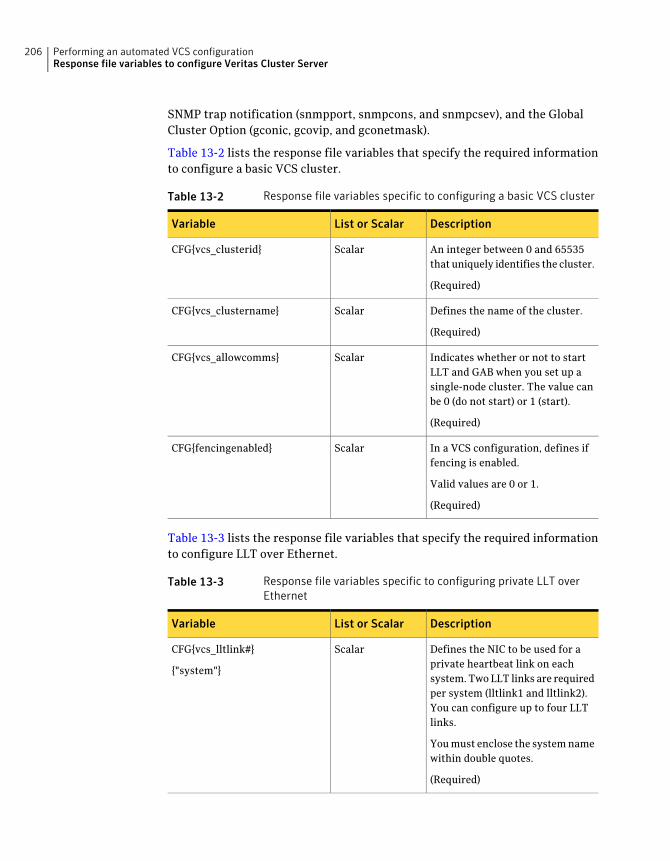
SNMP trap notification (snmpport, snmpcons, and snmpcsev), and the GlobalCluster Option (gconic, gcovip, and gconetmask).
Table 13-2 lists the response file variables that specify the required informationto configure a basic VCS cluster.
Table 13-2 Response file variables specific to configuring a basic VCS cluster
DescriptionList or ScalarVariable
An integer between 0 and 65535that uniquely identifies the cluster.
(Required)
ScalarCFG{vcs_clusterid}
Defines the name of the cluster.
(Required)
ScalarCFG{vcs_clustername}
Indicates whether or not to startLLT and GAB when you set up asingle-node cluster. The value canbe 0 (do not start) or 1 (start).
(Required)
ScalarCFG{vcs_allowcomms}
In a VCS configuration, defines iffencing is enabled.
Valid values are 0 or 1.
(Required)
ScalarCFG{fencingenabled}
Table 13-3 lists the response file variables that specify the required informationto configure LLT over Ethernet.
Table 13-3 Response file variables specific to configuring private LLT overEthernet
DescriptionList or ScalarVariable
Defines the NIC to be used for aprivate heartbeat link on eachsystem. Two LLT links are requiredper system (lltlink1 and lltlink2).You can configure up to four LLTlinks.
You must enclose the system namewithin double quotes.
(Required)
ScalarCFG{vcs_lltlink#}
{"system"}
Performing an automated VCS configurationResponse file variables to configure Veritas Cluster Server
206
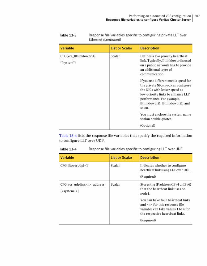
Table 13-3 Response file variables specific to configuring private LLT overEthernet (continued)
DescriptionList or ScalarVariable
Defines a low priority heartbeatlink. Typically, lltlinklowpri is usedon a public network link to providean additional layer ofcommunication.
If you use different media speed forthe private NICs, you can configurethe NICs with lesser speed aslow-priority links to enhance LLTperformance. For example,lltlinklowpri1, lltlinklowpri2, andso on.
You must enclose the system namewithin double quotes.
(Optional)
ScalarCFG{vcs_lltlinklowpri#}
{"system"}
Table 13-4 lists the response file variables that specify the required informationto configure LLT over UDP.
Table 13-4 Response file variables specific to configuring LLT over UDP
DescriptionList or ScalarVariable
Indicates whether to configureheartbeat link using LLT over UDP.
(Required)
ScalarCFG{lltoverudp}=1
Stores the IP address (IPv4 or IPv6)that the heartbeat link uses onnode1.
You can have four heartbeat linksand <n> for this response filevariable can take values 1 to 4 forthe respective heartbeat links.
(Required)
ScalarCFG{vcs_udplink<n>_address}
{<system1>}
207Performing an automated VCS configurationResponse file variables to configure Veritas Cluster Server
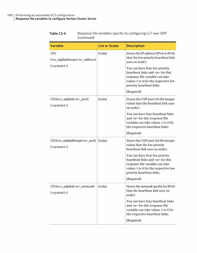
Table 13-4 Response file variables specific to configuring LLT over UDP(continued)
DescriptionList or ScalarVariable
Stores the IP address (IPv4 or IPv6)that the low priority heartbeat linkuses on node1.
You can have four low priorityheartbeat links and <n> for thisresponse file variable can takevalues 1 to 4 for the respective lowpriority heartbeat links.
(Required)
ScalarCFG
{vcs_udplinklowpri<n>_address}
{<system1>}
Stores the UDP port (16-bit integervalue) that the heartbeat link useson node1.
You can have four heartbeat linksand <n> for this response filevariable can take values 1 to 4 forthe respective heartbeat links.
(Required)
ScalarCFG{vcs_udplink<n>_port}
{<system1>}
Stores the UDP port (16-bit integervalue) that the low priorityheartbeat link uses on node1.
You can have four low priorityheartbeat links and <n> for thisresponse file variable can takevalues 1 to 4 for the respective lowpriority heartbeat links.
(Required)
ScalarCFG{vcs_udplinklowpri<n>_port}
{<system1>}
Stores the netmask (prefix for IPv6)that the heartbeat link uses onnode1.
You can have four heartbeat linksand <n> for this response filevariable can take values 1 to 4 forthe respective heartbeat links.
(Required)
ScalarCFG{vcs_udplink<n>_netmask}
{<system1>}
Performing an automated VCS configurationResponse file variables to configure Veritas Cluster Server
208
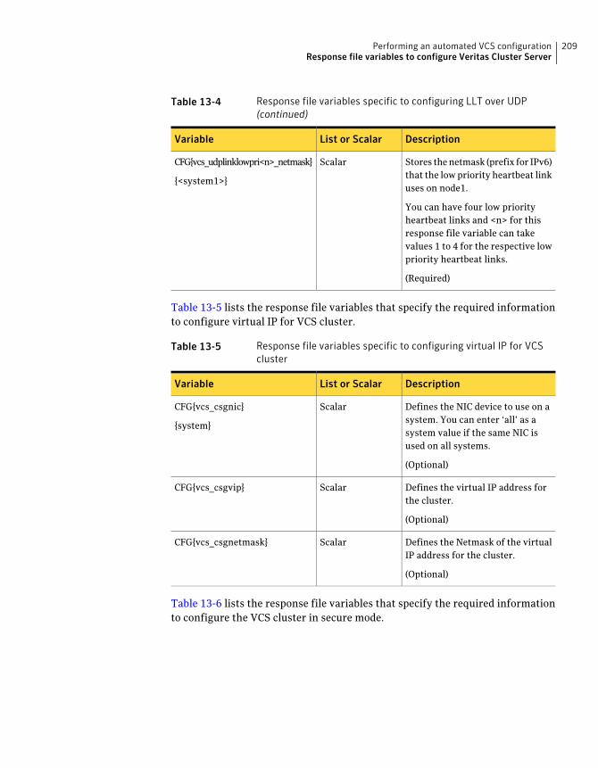
Table 13-4 Response file variables specific to configuring LLT over UDP(continued)
DescriptionList or ScalarVariable
Stores the netmask (prefix for IPv6)that the low priority heartbeat linkuses on node1.
You can have four low priorityheartbeat links and <n> for thisresponse file variable can takevalues 1 to 4 for the respective lowpriority heartbeat links.
(Required)
ScalarCFG{vcs_udplinklowpri<n>_netmask}
{<system1>}
Table 13-5 lists the response file variables that specify the required informationto configure virtual IP for VCS cluster.
Table 13-5 Response file variables specific to configuring virtual IP for VCScluster
DescriptionList or ScalarVariable
Defines the NIC device to use on asystem. You can enter ‘all’ as asystem value if the same NIC isused on all systems.
(Optional)
ScalarCFG{vcs_csgnic}
{system}
Defines the virtual IP address forthe cluster.
(Optional)
ScalarCFG{vcs_csgvip}
Defines the Netmask of the virtualIP address for the cluster.
(Optional)
ScalarCFG{vcs_csgnetmask}
Table 13-6 lists the response file variables that specify the required informationto configure the VCS cluster in secure mode.
209Performing an automated VCS configurationResponse file variables to configure Veritas Cluster Server
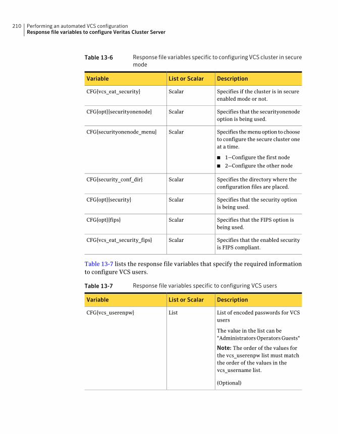
Table 13-6 Response file variables specific to configuring VCS cluster in securemode
DescriptionList or ScalarVariable
Specifies if the cluster is in secureenabled mode or not.
ScalarCFG{vcs_eat_security}
Specifies that the securityonenodeoption is being used.
ScalarCFG{opt}{securityonenode}
Specifies the menu option to chooseto configure the secure cluster oneat a time.
■ 1—Configure the first node
■ 2—Configure the other node
ScalarCFG{securityonenode_menu}
Specifies the directory where theconfiguration files are placed.
ScalarCFG{security_conf_dir}
Specifies that the security optionis being used.
ScalarCFG{opt}{security}
Specifies that the FIPS option isbeing used.
ScalarCFG{opt}{fips}
Specifies that the enabled securityis FIPS compliant.
ScalarCFG{vcs_eat_security_fips}
Table 13-7 lists the response file variables that specify the required informationto configure VCS users.
Table 13-7 Response file variables specific to configuring VCS users
DescriptionList or ScalarVariable
List of encoded passwords for VCSusers
The value in the list can be"Administrators Operators Guests"
Note: The order of the values forthe vcs_userenpw list must matchthe order of the values in thevcs_username list.
(Optional)
ListCFG{vcs_userenpw}
Performing an automated VCS configurationResponse file variables to configure Veritas Cluster Server
210
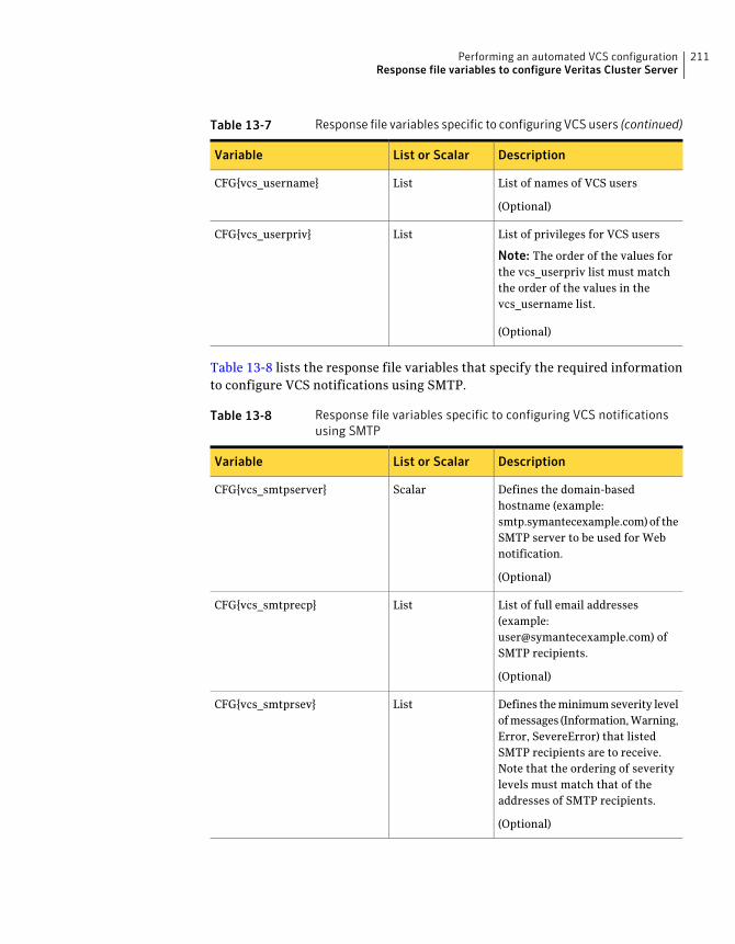
Table 13-7 Response file variables specific to configuring VCS users (continued)
DescriptionList or ScalarVariable
List of names of VCS users
(Optional)
ListCFG{vcs_username}
List of privileges for VCS users
Note: The order of the values forthe vcs_userpriv list must matchthe order of the values in thevcs_username list.
(Optional)
ListCFG{vcs_userpriv}
Table 13-8 lists the response file variables that specify the required informationto configure VCS notifications using SMTP.
Table 13-8 Response file variables specific to configuring VCS notificationsusing SMTP
DescriptionList or ScalarVariable
Defines the domain-basedhostname (example:smtp.symantecexample.com) of theSMTP server to be used for Webnotification.
(Optional)
ScalarCFG{vcs_smtpserver}
List of full email addresses(example:[email protected]) ofSMTP recipients.
(Optional)
ListCFG{vcs_smtprecp}
Defines the minimum severity levelof messages (Information, Warning,Error, SevereError) that listedSMTP recipients are to receive.Note that the ordering of severitylevels must match that of theaddresses of SMTP recipients.
(Optional)
ListCFG{vcs_smtprsev}
211Performing an automated VCS configurationResponse file variables to configure Veritas Cluster Server
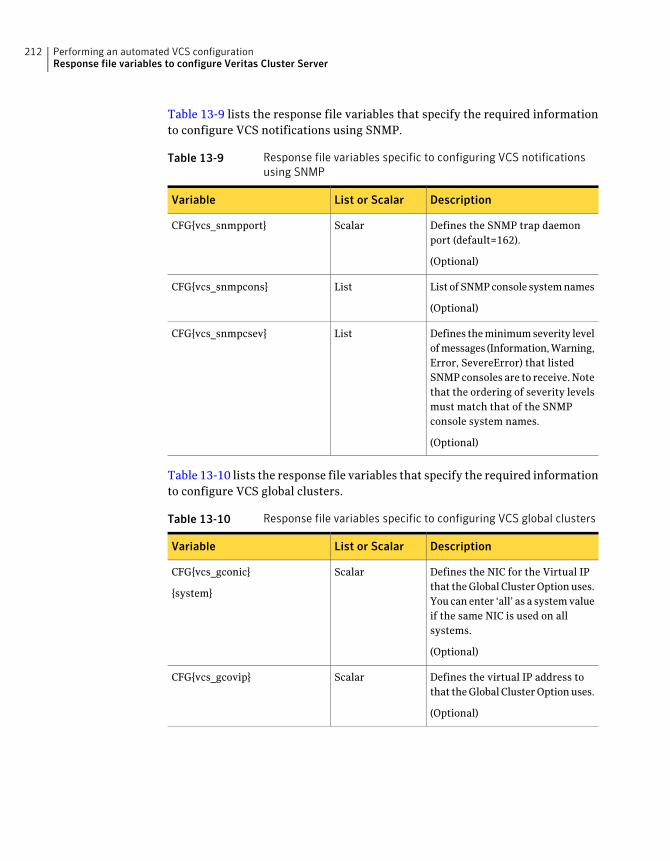
Table 13-9 lists the response file variables that specify the required informationto configure VCS notifications using SNMP.
Table 13-9 Response file variables specific to configuring VCS notificationsusing SNMP
DescriptionList or ScalarVariable
Defines the SNMP trap daemonport (default=162).
(Optional)
ScalarCFG{vcs_snmpport}
List of SNMP console system names
(Optional)
ListCFG{vcs_snmpcons}
Defines the minimum severity levelof messages (Information, Warning,Error, SevereError) that listedSNMP consoles are to receive. Notethat the ordering of severity levelsmust match that of the SNMPconsole system names.
(Optional)
ListCFG{vcs_snmpcsev}
Table 13-10 lists the response file variables that specify the required informationto configure VCS global clusters.
Table 13-10 Response file variables specific to configuring VCS global clusters
DescriptionList or ScalarVariable
Defines the NIC for the Virtual IPthat the Global Cluster Option uses.You can enter ‘all’ as a system valueif the same NIC is used on allsystems.
(Optional)
ScalarCFG{vcs_gconic}
{system}
Defines the virtual IP address tothat the Global Cluster Option uses.
(Optional)
ScalarCFG{vcs_gcovip}
Performing an automated VCS configurationResponse file variables to configure Veritas Cluster Server
212
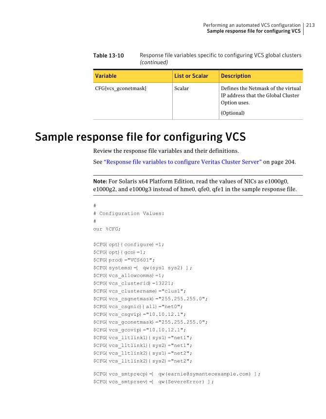
Table 13-10 Response file variables specific to configuring VCS global clusters(continued)
DescriptionList or ScalarVariable
Defines the Netmask of the virtualIP address that the Global ClusterOption uses.
(Optional)
ScalarCFG{vcs_gconetmask}
Sample response file for configuring VCSReview the response file variables and their definitions.
See “Response file variables to configure Veritas Cluster Server” on page 204.
Note: For Solaris x64 Platform Edition, read the values of NICs as e1000g0,e1000g2, and e1000g3 instead of hme0, qfe0, qfe1 in the sample response file.
#
# Configuration Values:
#
our %CFG;
$CFG{opt}{configure}=1;
$CFG{opt}{gco}=1;
$CFG{prod}="VCS601";
$CFG{systems}=[ qw(sys1 sys2) ];
$CFG{vcs_allowcomms}=1;
$CFG{vcs_clusterid}=13221;
$CFG{vcs_clustername}="clus1";
$CFG{vcs_csgnetmask}="255.255.255.0";
$CFG{vcs_csgnic}{all}="net0";
$CFG{vcs_csgvip}="10.10.12.1";
$CFG{vcs_gconetmask}="255.255.255.0";
$CFG{vcs_gcovip}="10.10.12.1";
$CFG{vcs_lltlink1}{sys1}="net1";
$CFG{vcs_lltlink1}{sys2}="net1";
$CFG{vcs_lltlink2}{sys1}="net2";
$CFG{vcs_lltlink2}{sys2}="net2";
$CFG{vcs_smtprecp}=[ qw([email protected]) ];
$CFG{vcs_smtprsev}=[ qw(SevereError) ];
213Performing an automated VCS configurationSample response file for configuring VCS

$CFG{vcs_smtpserver}="smtp.symantecexample.com";
$CFG{vcs_snmpcons}=[ qw(neptune) ];
$CFG{vcs_snmpcsev}=[ qw(SevereError) ];
$CFG{vcs_snmpport}=162;
1;
Performing an automated VCS configurationSample response file for configuring VCS
214
Performing an automatedI/O fencing configurationusing response files
This chapter includes the following topics:
■ Configuring I/O fencing using response files
■ Response file variables to configure disk-based I/O fencing
■ Sample response file for configuring disk-based I/O fencing
■ Response file variables to configure server-based I/O fencing
■ Sample response file for configuring server-based I/O fencing
■ Response file variables to configure non-SCSI-3 server-based I/O fencing
■ Sample response file for configuring non-SCSI-3 server-based I/O fencing
Configuring I/O fencing using response filesTypically, you can use the response file that the installer generates after youperform I/O fencing configuration to configure I/O fencing for VCS.
To configure I/O fencing using response files
1 Make sure that VCS is configured.
2 Based on whether you want to configure disk-based or server-based I/Ofencing, make sure you have completed the preparatory tasks.
See “About planning to configure I/O fencing” on page 95.
14Chapter
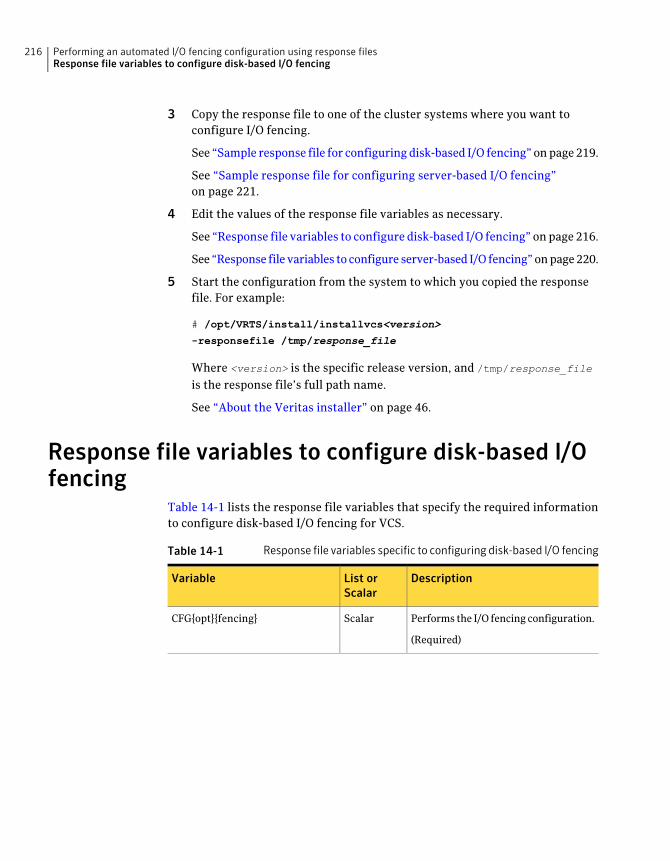
3 Copy the response file to one of the cluster systems where you want toconfigure I/O fencing.
See “Sample response file for configuring disk-based I/O fencing” on page 219.
See “Sample response file for configuring server-based I/O fencing”on page 221.
4 Edit the values of the response file variables as necessary.
See “Response file variables to configure disk-based I/O fencing” on page 216.
See “Response file variables to configure server-based I/O fencing” on page 220.
5 Start the configuration from the system to which you copied the responsefile. For example:
# /opt/VRTS/install/installvcs<version>
-responsefile /tmp/response_file
Where <version> is the specific release version, and /tmp/response_file
is the response file’s full path name.
See “About the Veritas installer” on page 46.
Response file variables to configure disk-based I/Ofencing
Table 14-1 lists the response file variables that specify the required informationto configure disk-based I/O fencing for VCS.
Table 14-1 Response file variables specific to configuring disk-based I/O fencing
DescriptionList orScalar
Variable
Performs the I/O fencing configuration.
(Required)
ScalarCFG{opt}{fencing}
Performing an automated I/O fencing configuration using response filesResponse file variables to configure disk-based I/O fencing
216
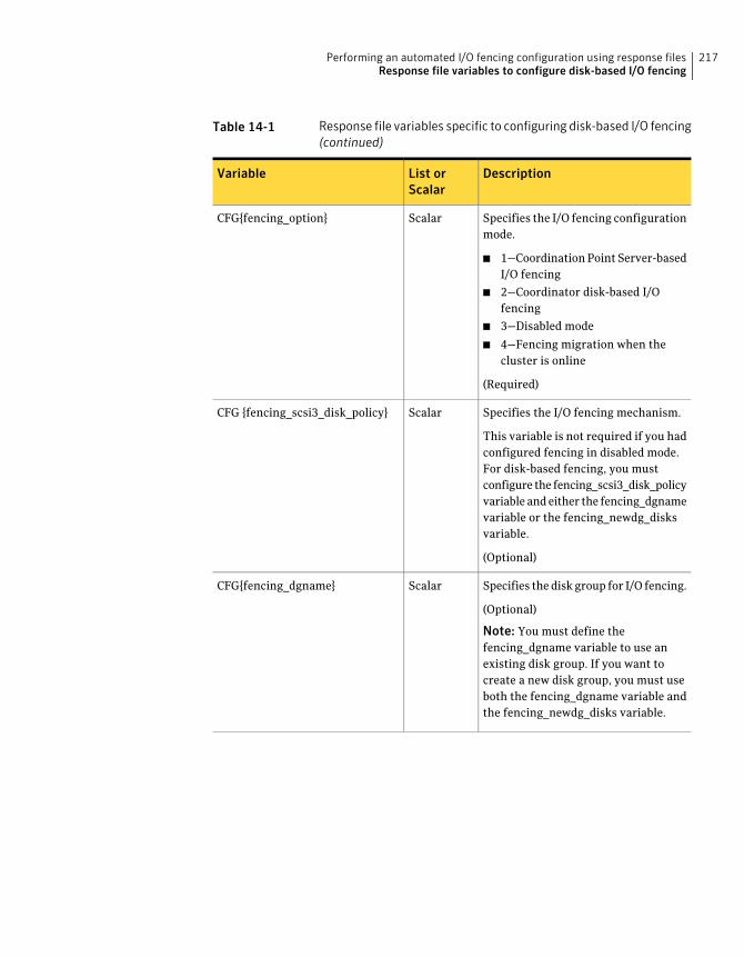
Table 14-1 Response file variables specific to configuring disk-based I/O fencing(continued)
DescriptionList orScalar
Variable
Specifies the I/O fencing configurationmode.
■ 1—Coordination Point Server-basedI/O fencing
■ 2—Coordinator disk-based I/Ofencing
■ 3—Disabled mode
■ 4—Fencing migration when thecluster is online
(Required)
ScalarCFG{fencing_option}
Specifies the I/O fencing mechanism.
This variable is not required if you hadconfigured fencing in disabled mode.For disk-based fencing, you mustconfigure the fencing_scsi3_disk_policyvariable and either the fencing_dgnamevariable or the fencing_newdg_disksvariable.
(Optional)
ScalarCFG {fencing_scsi3_disk_policy}
Specifies the disk group for I/O fencing.
(Optional)
Note: You must define thefencing_dgname variable to use anexisting disk group. If you want tocreate a new disk group, you must useboth the fencing_dgname variable andthe fencing_newdg_disks variable.
ScalarCFG{fencing_dgname}
217Performing an automated I/O fencing configuration using response filesResponse file variables to configure disk-based I/O fencing
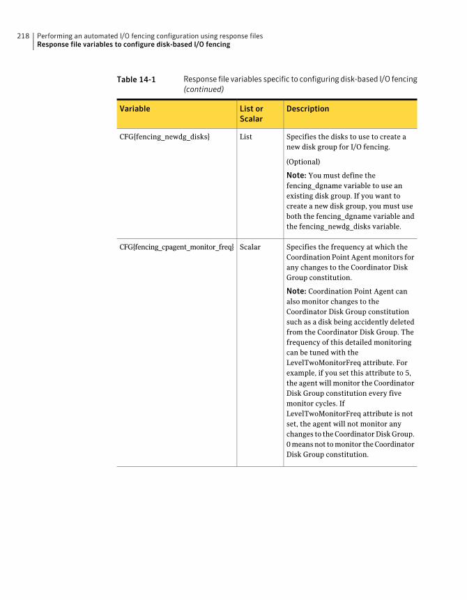
Table 14-1 Response file variables specific to configuring disk-based I/O fencing(continued)
DescriptionList orScalar
Variable
Specifies the disks to use to create anew disk group for I/O fencing.
(Optional)
Note: You must define thefencing_dgname variable to use anexisting disk group. If you want tocreate a new disk group, you must useboth the fencing_dgname variable andthe fencing_newdg_disks variable.
ListCFG{fencing_newdg_disks}
Specifies the frequency at which theCoordination Point Agent monitors forany changes to the Coordinator DiskGroup constitution.
Note: Coordination Point Agent canalso monitor changes to theCoordinator Disk Group constitutionsuch as a disk being accidently deletedfrom the Coordinator Disk Group. Thefrequency of this detailed monitoringcan be tuned with theLevelTwoMonitorFreq attribute. Forexample, if you set this attribute to 5,the agent will monitor the CoordinatorDisk Group constitution every fivemonitor cycles. IfLevelTwoMonitorFreq attribute is notset, the agent will not monitor anychanges to the Coordinator Disk Group.0 means not to monitor the CoordinatorDisk Group constitution.
ScalarCFG{fencing_cpagent_monitor_freq}
Performing an automated I/O fencing configuration using response filesResponse file variables to configure disk-based I/O fencing
218
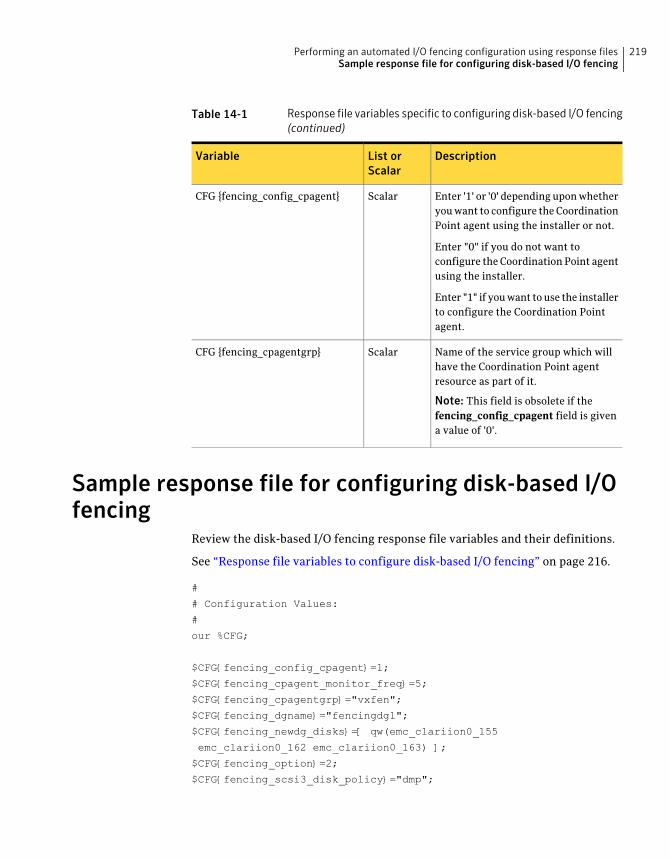
Table 14-1 Response file variables specific to configuring disk-based I/O fencing(continued)
DescriptionList orScalar
Variable
Enter '1' or '0' depending upon whetheryou want to configure the CoordinationPoint agent using the installer or not.
Enter "0" if you do not want toconfigure the Coordination Point agentusing the installer.
Enter "1" if you want to use the installerto configure the Coordination Pointagent.
ScalarCFG {fencing_config_cpagent}
Name of the service group which willhave the Coordination Point agentresource as part of it.
Note: This field is obsolete if thefencing_config_cpagent field is givena value of '0'.
ScalarCFG {fencing_cpagentgrp}
Sample response file for configuring disk-based I/Ofencing
Review the disk-based I/O fencing response file variables and their definitions.
See “Response file variables to configure disk-based I/O fencing” on page 216.
#
# Configuration Values:
#
our %CFG;
$CFG{fencing_config_cpagent}=1;
$CFG{fencing_cpagent_monitor_freq}=5;
$CFG{fencing_cpagentgrp}="vxfen";
$CFG{fencing_dgname}="fencingdg1";
$CFG{fencing_newdg_disks}=[ qw(emc_clariion0_155
emc_clariion0_162 emc_clariion0_163) ];
$CFG{fencing_option}=2;
$CFG{fencing_scsi3_disk_policy}="dmp";
219Performing an automated I/O fencing configuration using response filesSample response file for configuring disk-based I/O fencing
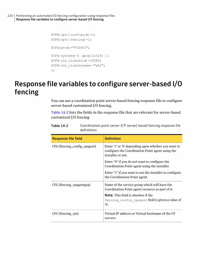
$CFG{opt}{configure}=1;
$CFG{opt}{fencing}=1;
$CFG{prod}="VCS601";
$CFG{systems}=[ qw(pilot25) ];
$CFG{vcs_clusterid}=32283;
$CFG{vcs_clustername}="whf";
1;
Response file variables to configure server-based I/Ofencing
You can use a coordination point server-based fencing response file to configureserver-based customized I/O fencing.
Table 14-2 lists the fields in the response file that are relevant for server-basedcustomized I/O fencing.
Table 14-2 Coordination point server (CP server) based fencing response filedefinitions
DefinitionResponse file field
Enter '1' or '0' depending upon whether you want toconfigure the Coordination Point agent using theinstaller or not.
Enter "0" if you do not want to configure theCoordination Point agent using the installer.
Enter "1" if you want to use the installer to configurethe Coordination Point agent.
CFG {fencing_config_cpagent}
Name of the service group which will have theCoordination Point agent resource as part of it.
Note: This field is obsolete if thefencing_config_cpagent field is given a value of'0'.
CFG {fencing_cpagentgrp}
Virtual IP address or Virtual hostname of the CPservers.
CFG {fencing_cps}
Performing an automated I/O fencing configuration using response filesResponse file variables to configure server-based I/O fencing
220
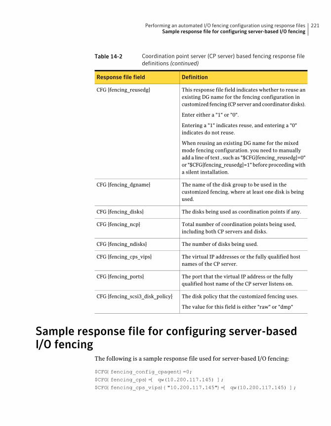
Table 14-2 Coordination point server (CP server) based fencing response filedefinitions (continued)
DefinitionResponse file field
This response file field indicates whether to reuse anexisting DG name for the fencing configuration incustomized fencing (CP server and coordinator disks).
Enter either a "1" or "0".
Entering a "1" indicates reuse, and entering a "0"indicates do not reuse.
When reusing an existing DG name for the mixedmode fencing configuration. you need to manuallyadd a line of text , such as "$CFG{fencing_reusedg}=0"or "$CFG{fencing_reusedg}=1" before proceeding witha silent installation.
CFG {fencing_reusedg}
The name of the disk group to be used in thecustomized fencing, where at least one disk is beingused.
CFG {fencing_dgname}
The disks being used as coordination points if any.CFG {fencing_disks}
Total number of coordination points being used,including both CP servers and disks.
CFG {fencing_ncp}
The number of disks being used.CFG {fencing_ndisks}
The virtual IP addresses or the fully qualified hostnames of the CP server.
CFG {fencing_cps_vips}
The port that the virtual IP address or the fullyqualified host name of the CP server listens on.
CFG {fencing_ports}
The disk policy that the customized fencing uses.
The value for this field is either "raw" or "dmp"
CFG {fencing_scsi3_disk_policy}
Sample response file for configuring server-basedI/O fencing
The following is a sample response file used for server-based I/O fencing:
$CFG{fencing_config_cpagent}=0;
$CFG{fencing_cps}=[ qw(10.200.117.145) ];
$CFG{fencing_cps_vips}{"10.200.117.145"}=[ qw(10.200.117.145) ];
221Performing an automated I/O fencing configuration using response filesSample response file for configuring server-based I/O fencing
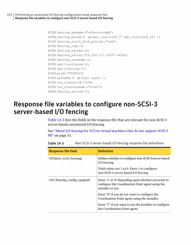
$CFG{fencing_dgname}="vxfencoorddg";
$CFG{fencing_disks}=[ qw(emc_clariion0_37 emc_clariion0_13) ];
$CFG{fencing_scsi3_disk_policy}="raw";
$CFG{fencing_ncp}=3;
$CFG{fencing_ndisks}=2;
$CFG{fencing_ports}{"10.200.117.145"}=14250;
$CFG{fencing_reusedg}=1;
$CFG{opt}{configure}=1;
$CFG{opt}{fencing}=1;
$CFG{prod}="VCS601";
$CFG{systems}=[ qw(sys1 sys2) ];
$CFG{vcs_clusterid}=1256;
$CFG{vcs_clustername}="clus1";
$CFG{fencing_option}=1;
Response file variables to configure non-SCSI-3server-based I/O fencing
Table 14-3 lists the fields in the response file that are relevant for non-SCSI-3server-based customized I/O fencing.
See “About I/O fencing for VCS in virtual machines that do not support SCSI-3PR” on page 31.
Table 14-3 Non-SCSI-3 server-based I/O fencing response file definitions
DefinitionResponse file field
Defines whether to configure non-SCSI-3 server-basedI/O fencing.
Valid values are 1 or 0. Enter 1 to configurenon-SCSI-3 server-based I/O fencing.
CFG{non_scsi3_fencing}
Enter '1' or '0' depending upon whether you want toconfigure the Coordination Point agent using theinstaller or not.
Enter "0" if you do not want to configure theCoordination Point agent using the installer.
Enter "1" if you want to use the installer to configurethe Coordination Point agent.
CFG {fencing_config_cpagent}
Performing an automated I/O fencing configuration using response filesResponse file variables to configure non-SCSI-3 server-based I/O fencing
222
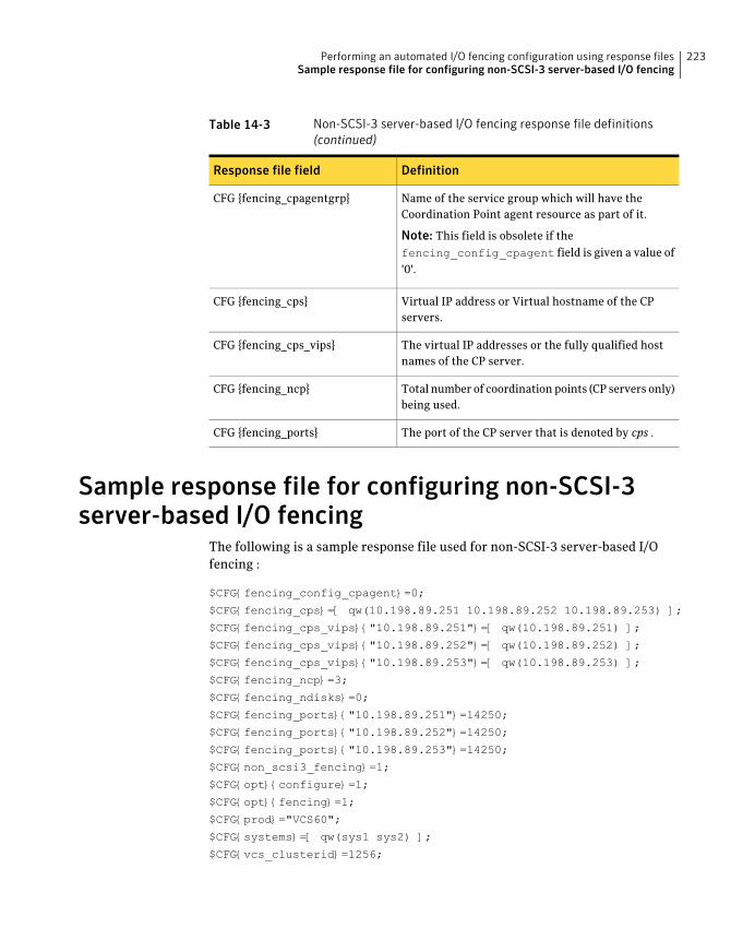
Table 14-3 Non-SCSI-3 server-based I/O fencing response file definitions(continued)
DefinitionResponse file field
Name of the service group which will have theCoordination Point agent resource as part of it.
Note: This field is obsolete if thefencing_config_cpagent field is given a value of'0'.
CFG {fencing_cpagentgrp}
Virtual IP address or Virtual hostname of the CPservers.
CFG {fencing_cps}
The virtual IP addresses or the fully qualified hostnames of the CP server.
CFG {fencing_cps_vips}
Total number of coordination points (CP servers only)being used.
CFG {fencing_ncp}
The port of the CP server that is denoted by cps .CFG {fencing_ports}
Sample response file for configuring non-SCSI-3server-based I/O fencing
The following is a sample response file used for non-SCSI-3 server-based I/Ofencing :
$CFG{fencing_config_cpagent}=0;
$CFG{fencing_cps}=[ qw(10.198.89.251 10.198.89.252 10.198.89.253) ];
$CFG{fencing_cps_vips}{"10.198.89.251"}=[ qw(10.198.89.251) ];
$CFG{fencing_cps_vips}{"10.198.89.252"}=[ qw(10.198.89.252) ];
$CFG{fencing_cps_vips}{"10.198.89.253"}=[ qw(10.198.89.253) ];
$CFG{fencing_ncp}=3;
$CFG{fencing_ndisks}=0;
$CFG{fencing_ports}{"10.198.89.251"}=14250;
$CFG{fencing_ports}{"10.198.89.252"}=14250;
$CFG{fencing_ports}{"10.198.89.253"}=14250;
$CFG{non_scsi3_fencing}=1;
$CFG{opt}{configure}=1;
$CFG{opt}{fencing}=1;
$CFG{prod}="VCS60";
$CFG{systems}=[ qw(sys1 sys2) ];
$CFG{vcs_clusterid}=1256;
223Performing an automated I/O fencing configuration using response filesSample response file for configuring non-SCSI-3 server-based I/O fencing

$CFG{vcs_clustername}="clus1";
$CFG{fencing_option}=1;
Performing an automated I/O fencing configuration using response filesSample response file for configuring non-SCSI-3 server-based I/O fencing
224
Manual installation
■ Chapter 15. Performing preinstallation tasks
■ Chapter 16. Manually installing VCS
■ Chapter 17. Manually configuring VCS
■ Chapter 18. Manually configuring the clusters for data integrity
6Section

226
Performing preinstallationtasks
This chapter includes the following topics:
■ Preparing for a manual installation
■ Requirements for installing VCS
Preparing for a manual installationBefore you start installation, log in as the superuser. Mount the disc, copy thefiles to a temporary location locally for your convenience. Each operating systemoccupies an entire disc. Each disc has an identical directory structure.
To prepare for installation
1 Log in as the superuser.
2 Mount the appropriate disc.
See “Mounting the product disc” on page 76.
3 Copy the files to a temporary location on the system.
# cp -r packages/* /tmp/install
Requirements for installing VCSReview requirements before you install.
See “Important preinstallation information for VCS” on page 35.
15Chapter

Performing preinstallation tasksRequirements for installing VCS
228
Manually installing VCS
This chapter includes the following topics:
■ About VCS manual installation
■ Installing VCS software manually
■ Installing VCS on Solaris 10 using JumpStart
■ Installing VCS on Solaris 11 using Automated Installer
About VCS manual installationYou can manually install and configure VCS instead of using the installvcsprogram.
A manual installation takes a lot of time, patience, and care. Symantec recommendsthat you use the installvcs program instead of the manual installation whenpossible.
Installing VCS software manuallyIf you manually install VCS software to upgrade your cluster, make sure to backup the previous VCS configuration files before you start the installation. Thesefiles follow:
■ /etc/VRTSvcs/conf/config
■ /etc/llttab
■ /etc/gabtab
■ /etc/llthosts
■ /etc/default/vcs
16Chapter
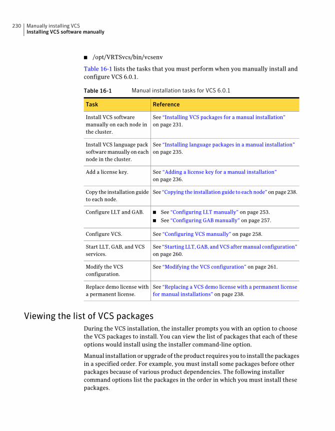
■ /opt/VRTSvcs/bin/vcsenv
Table 16-1 lists the tasks that you must perform when you manually install andconfigure VCS 6.0.1.
Table 16-1 Manual installation tasks for VCS 6.0.1
ReferenceTask
See “Installing VCS packages for a manual installation”on page 231.
Install VCS softwaremanually on each node inthe cluster.
See “Installing language packages in a manual installation”on page 235.
Install VCS language packsoftware manually on eachnode in the cluster.
See “Adding a license key for a manual installation”on page 236.
Add a license key.
See “Copying the installation guide to each node” on page 238.Copy the installation guideto each node.
■ See “Configuring LLT manually” on page 253.
■ See “Configuring GAB manually” on page 257.
Configure LLT and GAB.
See “Configuring VCS manually” on page 258.Configure VCS.
See “Starting LLT, GAB, and VCS after manual configuration”on page 260.
Start LLT, GAB, and VCSservices.
See “Modifying the VCS configuration” on page 261.Modify the VCSconfiguration.
See “Replacing a VCS demo license with a permanent licensefor manual installations” on page 238.
Replace demo license witha permanent license.
Viewing the list of VCS packagesDuring the VCS installation, the installer prompts you with an option to choosethe VCS packages to install. You can view the list of packages that each of theseoptions would install using the installer command-line option.
Manual installation or upgrade of the product requires you to install the packagesin a specified order. For example, you must install some packages before otherpackages because of various product dependencies. The following installercommand options list the packages in the order in which you must install thesepackages.
Manually installing VCSInstalling VCS software manually
230
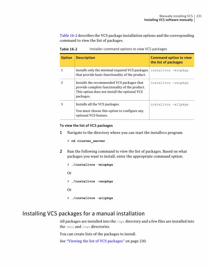
Table 16-2 describes the VCS package installation options and the correspondingcommand to view the list of packages.
Table 16-2 Installer command options to view VCS packages
Command option to viewthe list of packages
DescriptionOption
installvcs -minpkgsInstalls only the minimal required VCS packagesthat provide basic functionality of the product.
1
installvcs -recpkgsInstalls the recommended VCS packages thatprovide complete functionality of the product.This option does not install the optional VCSpackages.
2
installvcs -allpkgsInstalls all the VCS packages.
You must choose this option to configure anyoptional VCS feature.
3
To view the list of VCS packages
1 Navigate to the directory where you can start the installvcs program.
# cd cluster_server
2 Run the following command to view the list of packages. Based on whatpackages you want to install, enter the appropriate command option:
# ./installvcs -minpkgs
Or
# ./installvcs -recpkgs
Or
# ./installvcs -allpkgs
Installing VCS packages for a manual installationAll packages are installed into the /opt directory and a few files are installed intothe /etc and /var directories.
You can create lists of the packages to install.
See “Viewing the list of VCS packages” on page 230.
231Manually installing VCSInstalling VCS software manually
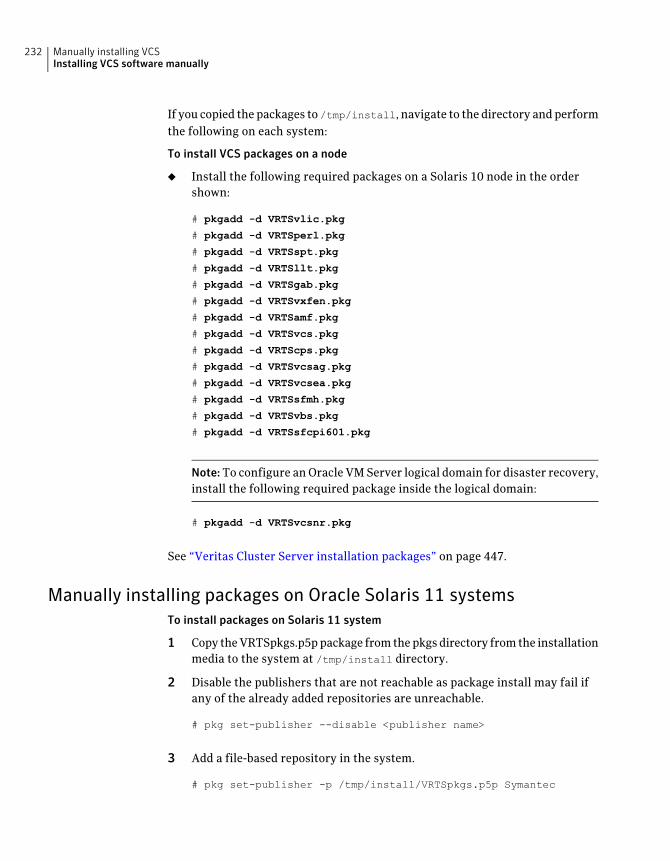
If you copied the packages to /tmp/install, navigate to the directory and performthe following on each system:
To install VCS packages on a node
◆ Install the following required packages on a Solaris 10 node in the ordershown:
# pkgadd -d VRTSvlic.pkg
# pkgadd -d VRTSperl.pkg
# pkgadd -d VRTSspt.pkg
# pkgadd -d VRTSllt.pkg
# pkgadd -d VRTSgab.pkg
# pkgadd -d VRTSvxfen.pkg
# pkgadd -d VRTSamf.pkg
# pkgadd -d VRTSvcs.pkg
# pkgadd -d VRTScps.pkg
# pkgadd -d VRTSvcsag.pkg
# pkgadd -d VRTSvcsea.pkg
# pkgadd -d VRTSsfmh.pkg
# pkgadd -d VRTSvbs.pkg
# pkgadd -d VRTSsfcpi601.pkg
Note:To configure an Oracle VM Server logical domain for disaster recovery,install the following required package inside the logical domain:
# pkgadd -d VRTSvcsnr.pkg
See “Veritas Cluster Server installation packages” on page 447.
Manually installing packages on Oracle Solaris 11 systemsTo install packages on Solaris 11 system
1 Copy the VRTSpkgs.p5p package from the pkgs directory from the installationmedia to the system at /tmp/install directory.
2 Disable the publishers that are not reachable as package install may fail ifany of the already added repositories are unreachable.
# pkg set-publisher --disable <publisher name>
3 Add a file-based repository in the system.
# pkg set-publisher -p /tmp/install/VRTSpkgs.p5p Symantec
Manually installing VCSInstalling VCS software manually
232
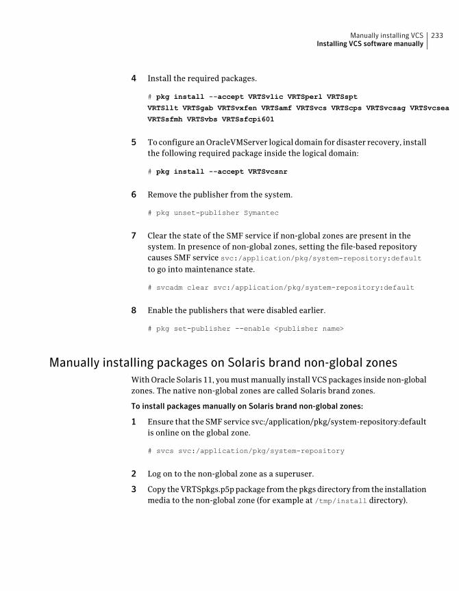
4 Install the required packages.
# pkg install --accept VRTSvlic VRTSperl VRTSspt
VRTSllt VRTSgab VRTSvxfen VRTSamf VRTSvcs VRTScps VRTSvcsag VRTSvcsea
VRTSsfmh VRTSvbs VRTSsfcpi601
5 To configure an OracleVMServer logical domain for disaster recovery, installthe following required package inside the logical domain:
# pkg install --accept VRTSvcsnr
6 Remove the publisher from the system.
# pkg unset-publisher Symantec
7 Clear the state of the SMF service if non-global zones are present in thesystem. In presence of non-global zones, setting the file-based repositorycauses SMF service svc:/application/pkg/system-repository:default
to go into maintenance state.
# svcadm clear svc:/application/pkg/system-repository:default
8 Enable the publishers that were disabled earlier.
# pkg set-publisher --enable <publisher name>
Manually installing packages on Solaris brand non-global zonesWith Oracle Solaris 11, you must manually install VCS packages inside non-globalzones. The native non-global zones are called Solaris brand zones.
To install packages manually on Solaris brand non-global zones:
1 Ensure that the SMF service svc:/application/pkg/system-repository:defaultis online on the global zone.
# svcs svc:/application/pkg/system-repository
2 Log on to the non-global zone as a superuser.
3 Copy the VRTSpkgs.p5p package from the pkgs directory from the installationmedia to the non-global zone (for example at /tmp/install directory).
233Manually installing VCSInstalling VCS software manually
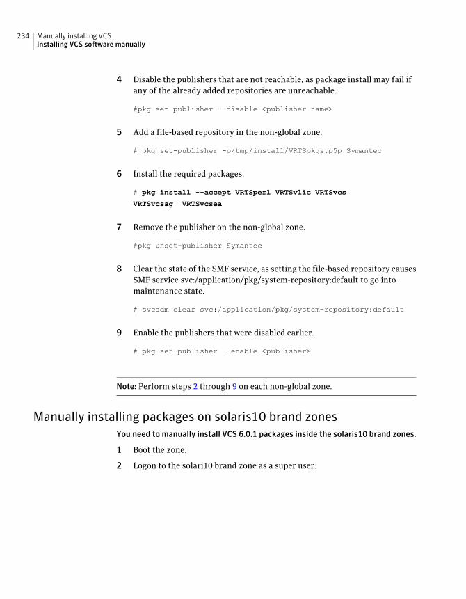
4 Disable the publishers that are not reachable, as package install may fail ifany of the already added repositories are unreachable.
#pkg set-publisher --disable <publisher name>
5 Add a file-based repository in the non-global zone.
# pkg set-publisher -p/tmp/install/VRTSpkgs.p5p Symantec
6 Install the required packages.
# pkg install --accept VRTSperl VRTSvlic VRTSvcs
VRTSvcsag VRTSvcsea
7 Remove the publisher on the non-global zone.
#pkg unset-publisher Symantec
8 Clear the state of the SMF service, as setting the file-based repository causesSMF service svc:/application/pkg/system-repository:default to go intomaintenance state.
# svcadm clear svc:/application/pkg/system-repository:default
9 Enable the publishers that were disabled earlier.
# pkg set-publisher --enable <publisher>
Note: Perform steps 2 through 9 on each non-global zone.
Manually installing packages on solaris10 brand zonesYou need to manually install VCS 6.0.1 packages inside the solaris10 brand zones.
1 Boot the zone.
2 Logon to the solari10 brand zone as a super user.
Manually installing VCSInstalling VCS software manually
234
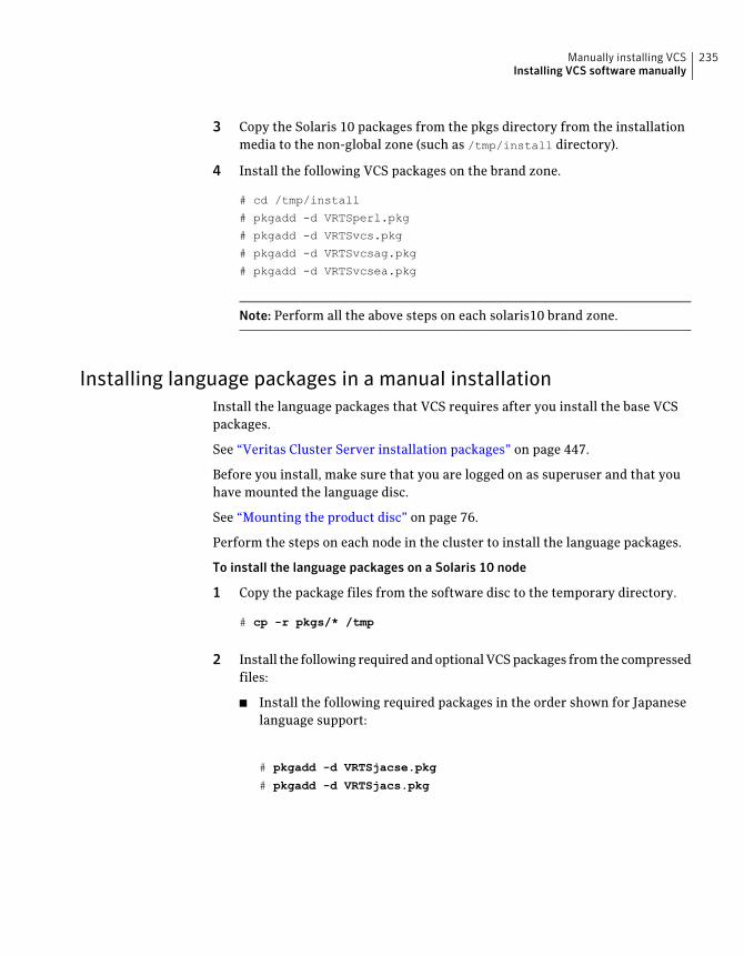
3 Copy the Solaris 10 packages from the pkgs directory from the installationmedia to the non-global zone (such as /tmp/install directory).
4 Install the following VCS packages on the brand zone.
# cd /tmp/install
# pkgadd -d VRTSperl.pkg
# pkgadd -d VRTSvcs.pkg
# pkgadd -d VRTSvcsag.pkg
# pkgadd -d VRTSvcsea.pkg
Note: Perform all the above steps on each solaris10 brand zone.
Installing language packages in a manual installationInstall the language packages that VCS requires after you install the base VCSpackages.
See “Veritas Cluster Server installation packages” on page 447.
Before you install, make sure that you are logged on as superuser and that youhave mounted the language disc.
See “Mounting the product disc” on page 76.
Perform the steps on each node in the cluster to install the language packages.
To install the language packages on a Solaris 10 node
1 Copy the package files from the software disc to the temporary directory.
# cp -r pkgs/* /tmp
2 Install the following required and optional VCS packages from the compressedfiles:
■ Install the following required packages in the order shown for Japaneselanguage support:
# pkgadd -d VRTSjacse.pkg
# pkgadd -d VRTSjacs.pkg
235Manually installing VCSInstalling VCS software manually
To install the language packages on a Solaris 11 node:
1 Copy the VRTSpkgs.p5p package from the pkgs directory from the installationmedia to the system at /tmp/install directory.
2 Add a file-based repository in the system.
# pkg set-publisher -p /tmp/install/VRTSpkgs.p5p Symantec
3 Install the following required packages in the order shown for Japaneselanguage support:
# pkg install --accept VRTSjacse
# pkg install --accept VRTSjacs
Adding a license key for a manual installationYou can either add the VCS license keys or use keyless licensing for VCS.
See “Setting or changing the product level for keyless licensing” on page 236.
After you have installed all packages on each cluster node, use the vxlicinst
command to add the VCS license key on each system:
# vxlicinst -k XXXX-XXXX-XXXX-XXXX-XXXX-XXX
Setting or changing the product level for keyless licensingThe keyless licensing method uses product levels to determine the Veritas productsand functionality that are licensed.
For more information to use keyless licensing and to download the managementserver, see the following URL:
http://go.symantec.com/vom
When you set the product license level for the first time, you enable keylesslicensing for that system. If you install with the product installer and select thekeyless option, you are prompted to select the product and feature level that youwant to license.
After you install, you can change product license levels at any time to reflect theproducts and functionality that you want to license. When you set a product level,you agree that you have the license for that functionality.
Manually installing VCSInstalling VCS software manually
236
To set or change the product level
1 Change your current working directory:
# cd /opt/VRTSvlic/bin
2 View the current setting for the product level.
# ./vxkeyless -v display
3 View the possible settings for the product level.
# ./vxkeyless displayall
4 Set the desired product level.
# ./vxkeyless set prod_levels
where prod_levels is a comma-separated list of keywords. The keywords arethe product levels as shown by the output of step 3.
If you want to remove keyless licensing and enter a key, you must clear the keylesslicenses. Use the NONE keyword to clear all keys from the system.
Warning: Clearing the keys disables the Veritas products until you install a newkey or set a new product level.
To clear the product license level
1 View the current setting for the product license level.
# ./vxkeyless [-v] display
2 If there are keyless licenses installed, remove all keyless licenses:
# ./vxkeyless [-q] set NONE
For more details on using the vxkeyless utility, see the vxkeyless(1m) manualpage.
Checking licensing information on the system for a manualinstallationUse the vxlicrep utility to display information about all Veritas licenses on asystem. For example, enter:
237Manually installing VCSInstalling VCS software manually
# vxlicrep
From the output, you can determine the following:
■ The license key
■ The type of license
■ The product for which it applies
■ Its expiration date, if one existsDemo keys have expiration dates, while permanent keys and site keys do not.
Replacing a VCS demo license with a permanent license formanual installationsWhen a VCS demo key license expires, you can replace it with a permanent licenseusing the vxlicinst program.
See “Checking licensing information on the system” on page 148.
Copying the installation guide to each nodeAfter you install VCS, Symantec recommends that you copy the PDF version ofthis guide from the installation disc to the /opt/VRTS/docs directory on each nodeto make it available for reference. The PDF is located atcluster_server/docs/vcs_install_version_platform.pdf, where version
is the release version and platform is the name of the operating
system.
Installing VCS on Solaris 10 using JumpStartThis installation method applies only to Solaris 10. These JumpStart instructionsassume a working knowledge of JumpStart. See the JumpStart documentationthat came with your operating system for details on using JumpStart.
Upgrading is not supported. The following procedure assumes a stand-aloneconfiguration.
For the language pack, you can use JumpStart to install packages. You add thelanguage packages in the script, and put those files in the JumpStart serverdirectory.
You can use a Flash archive to install VCS and the operating system in conjunctionwith JumpStart.
See “Using a Flash archive to install VCS and the operating system” on page 242.
Manually installing VCSInstalling VCS on Solaris 10 using JumpStart
238
Overview of JumpStart installation tasksReview the summary of tasks before you perform the JumpStart installation.
Summary of tasks
1 Add a client (register to the JumpStart server). See the JumpStartdocumentation that came with your operating system for details.
2 Read the JumpStart installation instructions.
3 Generate the finish scripts.
See “Generating the finish scripts” on page 239.
4 Prepare shared storage installation resources.
See “Preparing installation resources” on page 240.
5 Modify the rules file for JumpStart.
See the JumpStart documentation that came with your operating system fordetails.
6 Install the operating system using the JumpStart server.
7 When the system is up and running, run the installer command from theinstallation media to configure the Veritas software.
# /opt/VRTS/install/installer -configure
See “About the Veritas installer” on page 46.
Generating the finish scriptsPerform these steps to generate the finish scripts to install VCS.
239Manually installing VCSInstalling VCS on Solaris 10 using JumpStart
To generate the script
1 Run the product installer program to generate the scripts for all products.
./installer -jumpstart directory_to_generate_scripts
Or
./install<productname> -jumpstart directory_to_generate_script
where <productname> is the product's installation command, anddirectory_to_generate_scripts is where you want to put the product's script.
For example:
# ./installvcs -jumpstart /js_scripts
2 Modify the JumpStart script according to your requirements. You must modifythe BUILDSRC and ENCAPSRC values. Keep the values aligned with theresource location values.
BUILDSRC="hostname_or_ip:/path_to_pkgs"
// If you don't want to encapsulate the root disk automatically
// comment out the following line.
ENCAPSRC="hostname_or_ip:/path_to_encap_script"
Preparing installation resourcesPrepare resources for the JumpStart installation.
Manually installing VCSInstalling VCS on Solaris 10 using JumpStart
240
To prepare the resources
1 Copy the pkgs directory of the installation media to the shared storage.
# cd /path_to_installation_media
# cp -r pkgs BUILDSRC
2 Generate the response file with the list of packages.
# cd BUILDSRC/pkgs/
# pkgask -r package_name.response -d /
BUILDSRC/pkgs/packages_name.pkg
3 Create the adminfile file under BUILDSRC/pkgs/ directory.
mail=
instance=overwrite
partial=nocheck
runlevel=quit
idepend=quit
rdepend=nocheck
space=quit
setuid=nocheck
conflict=nocheck
action=nocheck
basedir=default
Adding language pack information to the finish fileTo add the language pack information to the finish file, perform the followingprocedure.
241Manually installing VCSInstalling VCS on Solaris 10 using JumpStart
To add the language pack information to the finish file
1 For the language pack, copy the language packages from the language packinstallation disc to the shared storage.
# cd /cdrom/cdrom0/pkgs
# cp -r * BUILDSRC/pkgs
If you downloaded the language pack:
# cd /path_to_language_pack_installation_media/pkgs
# cp -r * BUILDSRC/pkgs
2 In the finish script, copy the product package information and replace theproduct packages with language packages.
3 The finish script resembles:
. . .
for PKG in product_packages
do
...
done. . .
for PKG in language_packages
do
...
done. . .
Using a Flash archive to install VCS and the operating systemYou can only use Flash archive on the Solaris 10 operating system. In the followingoutline, refer to Solaris documentation for Solaris-specific tasks.
Note: Symantec does not support Flash Archive installation if the root disk of themaster system is encapsulated.
The following is an overview of the creation and installation of a Flash archivewith Veritas software.
■ If you plan to start flar (flash archive) creation from bare metal, perform step1 through step 10.
■ If you plan to start flar creation from a system where you have installed, butnot configured the product, perform step 1 through step 4. Skip step 5 andfinish step 6 through step 10.
Manually installing VCSInstalling VCS on Solaris 10 using JumpStart
242
■ If you plan to start flar creation from a system where you have installed andconfigured the product, perform step 5 through step 10.
Flash archive creation overview
1 Ensure that you have installed Solaris 10 on the master system.
2 Use JumpStart to create a clone of a system.
3 Reboot the cloned system.
4 Install the Veritas products on the master system.
Perform one of the installation procedures from this guide.
5 If you have configured the product on the master system, create thevrts_deployment.sh file and the vrts_deployment.cf file and copy themto the master system.
See “Creating the Veritas post-deployment scripts” on page 243.
6 Use the flarcreate command to create the Flash archive on the mastersystem.
7 Copy the archive back to the JumpStart server.
8 Use JumpStart to install the Flash archive to the selected systems.
9 Configure the Veritas product on all nodes in the cluster. Start configurationwith the following command:
See “About the Veritas installer” on page 46.
10 Perform post-installation and configuration tasks.
See the product installation guide for the post-installation and configurationtasks.
Creating the Veritas post-deployment scriptsThe generated files vrts_deployment.sh and vrts_post-deployment.cf arecustomized Flash archive post-deployment scripts. These files clean up Veritasproduct settings on a cloned system before you reboot it for the first time. Includethese files in your Flash archives.
To create the post-deployment scripts
1 Mount the product disc.
2 From the prompt, run the -flash_archive option for the installer. Specifya directory where you want to create the files.
# ./installer -flash_archive /tmp
243Manually installing VCSInstalling VCS on Solaris 10 using JumpStart

3 Copy the vrts_postedeployment.sh file and the vrts_postedeployment.cf fileto the golden system.
4 On the golden system perform the following:
■ Put the vrts_postdeployment.sh file in the /etc/flash/postdeploymentdirectory.
■ Put the vrts_postdeployment.cf file in the /etc/vx directory.
5 Make sure that the two files have the following ownership and permissions:
# chown root:root /etc/flash/postdeployment/vrts_postdeployment.sh
# chmod 755 /etc/flash/postdeployment/vrts_postdeployment.sh
# chown root:root /etc/vx/vrts_postdeployment.cf
# chmod 644 /etc/vx/vrts_postdeployment.cf
Note that you only need these files in a Flash archive where you have installedVeritas products.
InstallingVCSonSolaris 11usingAutomated InstallerYou can use the Oracle Solaris Automated Installer (AI) to install the Solaris 11operating system on multiple client systems in a network. AI performs a hands-freeinstallation (automated installation without manual interactions) of both x86 andSPARC systems. You can also use AI media (AI bootable image, provided by Oracle,which can be downloaded from the Oracle Web site) to install the Oracle SolarisOS on a single SPARC or x86 platform. All cases require access to a packagerepository on the network to complete the installation.
About Automated InstallationAI automates the installation of the Oracle Solaris 11 OS on one or more SPARCor x86 clients in a network. Automated Installation applies to Solaris 11 only. Youcan install the Oracle Solaris OS on many different types of clients.The clientscan differ in:
■ architecture
■ memory charecteristics
■ MAC address
■ IP address
■ CPU
Manually installing VCSInstalling VCS on Solaris 11 using Automated Installer
244
The installations can differ depending on specifications including networkconfiguration and packages installed.
An automated installation of a client in a local network consists of the followinghigh-level steps:
1 A client system boots and gets IP information from the DHCP server
2 Characteristics of the client determine which AI service and which installationinstructions are used to install the client.
3 The installer uses the AI service instructions to pull the correct packagesfrom the package repositories and install the Oracle Solaris OS on the client.
Using Automated InstallerTo use Automated Installer to install systems over the network, set up DHCP andset up an AI service on an AI server. The DHCP server and AI server can be thesame system or two different systems.
Make sure that the systems can access an Oracle Solaris Image Packaging System(IPS) package repository. The IPS package repository can reside on the AI server,on another server on the local network, or on the Internet.
An AI service is associated with a SPARC or x86 AI install image and one or moresets of installation instructions. The installation instructions specify one or moreIPS package repositories from where the system retrieves the packages neededto complete the installation. The installation instructions also include the namesof additional packages to install and information such as target device and partitioninformation. You can also specify instructions for post-installation configurationof the system.
Consider the operating systems and packages you are installing on the systems.Depending on your configuration and needs, you may want do one of the following:
■ If two systems have different architectures or need to be installed with differentversions of the Oracle Solaris OS, create two AI services, and associate eachAI service with a different AI image.
■ If two systems need to be installed with the same version of the Oracle SolarisOS but need to be installed differently in other ways, create two sets ofinstallation instructions for the AI service. The different installationinstructions can specify different packages to install or a different slice as theinstall target.
The installation begins when you boot the system. DHCP directs the system tothe AI install server, and the system accesses the install service and the installationinstructions within that service.
245Manually installing VCSInstalling VCS on Solaris 11 using Automated Installer
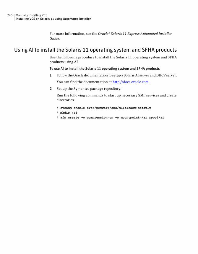
For more information, see the Oracle® Solaris 11 Express Automated InstallerGuide.
Using AI to install the Solaris 11 operating system and SFHA productsUse the following procedure to install the Solaris 11 operating system and SFHAproducts using AI.
To use AI to install the Solaris 11 operating system and SFHA products
1 Follow the Oracle documentation to setup a Solaris AI server and DHCP server.
You can find the documentation at http://docs.oracle.com.
2 Set up the Symantec package repository.
Run the following commands to start up necessary SMF services and createdirectories:
# svcadm enable svc:/network/dns/multicast:default
# mkdir /ai
# zfs create -o compression=on -o mountpoint=/ai rpool/ai
Manually installing VCSInstalling VCS on Solaris 11 using Automated Installer
246
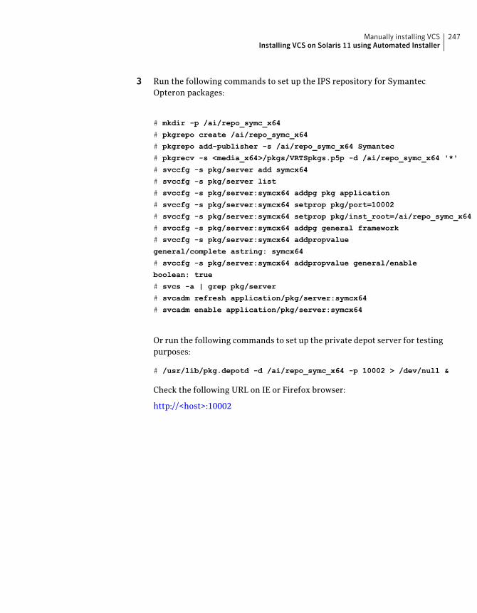
3 Run the following commands to set up the IPS repository for SymantecOpteron packages:
# mkdir -p /ai/repo_symc_x64
# pkgrepo create /ai/repo_symc_x64
# pkgrepo add-publisher -s /ai/repo_symc_x64 Symantec
# pkgrecv -s <media_x64>/pkgs/VRTSpkgs.p5p -d /ai/repo_symc_x64 '*'
# svccfg -s pkg/server add symcx64
# svccfg -s pkg/server list
# svccfg -s pkg/server:symcx64 addpg pkg application
# svccfg -s pkg/server:symcx64 setprop pkg/port=10002
# svccfg -s pkg/server:symcx64 setprop pkg/inst_root=/ai/repo_symc_x64
# svccfg -s pkg/server:symcx64 addpg general framework
# svccfg -s pkg/server:symcx64 addpropvalue
general/complete astring: symcx64
# svccfg -s pkg/server:symcx64 addpropvalue general/enable
boolean: true
# svcs -a | grep pkg/server
# svcadm refresh application/pkg/server:symcx64
# svcadm enable application/pkg/server:symcx64
Or run the following commands to set up the private depot server for testingpurposes:
# /usr/lib/pkg.depotd -d /ai/repo_symc_x64 -p 10002 > /dev/null &
Check the following URL on IE or Firefox browser:
http://<host>:10002
247Manually installing VCSInstalling VCS on Solaris 11 using Automated Installer
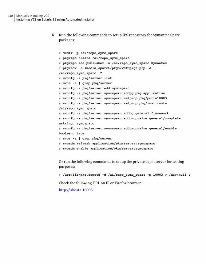
4 Run the following commands to setup IPS repository for Symantec Sparcpackages:
# mkdir -p /ai/repo_symc_sparc
# pkgrepo create /ai/repo_symc_sparc
# pkgrepo add-publisher -s /ai/repo_symc_sparc Symantec
# pkgrecv -s <media_sparc>/pkgs/VRTSpkgs.p5p -d
/ai/repo_symc_sparc '*'
# svccfg -s pkg/server list
# svcs -a | grep pkg/server
# svccfg -s pkg/server add symcsparc
# svccfg -s pkg/server:symcsparc addpg pkg application
# svccfg -s pkg/server:symcsparc setprop pkg/port=10003
# svccfg -s pkg/server:symcsparc setprop pkg/inst_root=
/ai/repo_symc_sparc
# svccfg -s pkg/server:symcsparc addpg general framework
# svccfg -s pkg/server:symcsparc addpropvalue general/complete
astring: symcsparc
# svccfg -s pkg/server:symcsparc addpropvalue general/enable
boolean: true
# svcs -a | grep pkg/server
# svcadm refresh application/pkg/server:symcsparc
# svcadm enable application/pkg/server:symcsparc
Or run the following commands to set up the private depot server for testingpurposes:
# /usr/lib/pkg.depotd -d /ai/repo_symc_sparc -p 10003 > /dev/null &
Check the following URL on IE or Firefox browser:
http://<host>:10003
Manually installing VCSInstalling VCS on Solaris 11 using Automated Installer
248
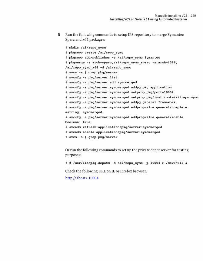
5 Run the following commands to setup IPS repository to merge SymantecSparc and x64 packages:
# mkdir /ai/repo_symc
# pkgrepo create /ai/repo_symc
# pkgrepo add-publisher -s /ai/repo_symc Symantec
# pkgmerge -s arch=sparc,/ai/repo_symc_sparc -s arch=i386,
/ai/repo_symc_x64 -d /ai/repo_symc
# svcs -a | grep pkg/server
# svccfg -s pkg/server list
# svccfg -s pkg/server add symcmerged
# svccfg -s pkg/server:symcmerged addpg pkg application
# svccfg -s pkg/server:symcmerged setprop pkg/port=10004
# svccfg -s pkg/server:symcmerged setprop pkg/inst_root=/ai/repo_symc
# svccfg -s pkg/server:symcmerged addpg general framework
# svccfg -s pkg/server:symcmerged addpropvalue general/complete
astring: symcmerged
# svccfg -s pkg/server:symcmerged addpropvalue general/enable
boolean: true
# svcadm refresh application/pkg/server:symcmerged
# svcadm enable application/pkg/server:symcmerged
# svcs -a | grep pkg/server
Or run the following commands to set up the private depot server for testingpurposes:
# # /usr/lib/pkg.depotd -d /ai/repo_symc -p 10004 > /dev/null &
Check the following URL on IE or Firefox browser:
http://<host>:10004
249Manually installing VCSInstalling VCS on Solaris 11 using Automated Installer
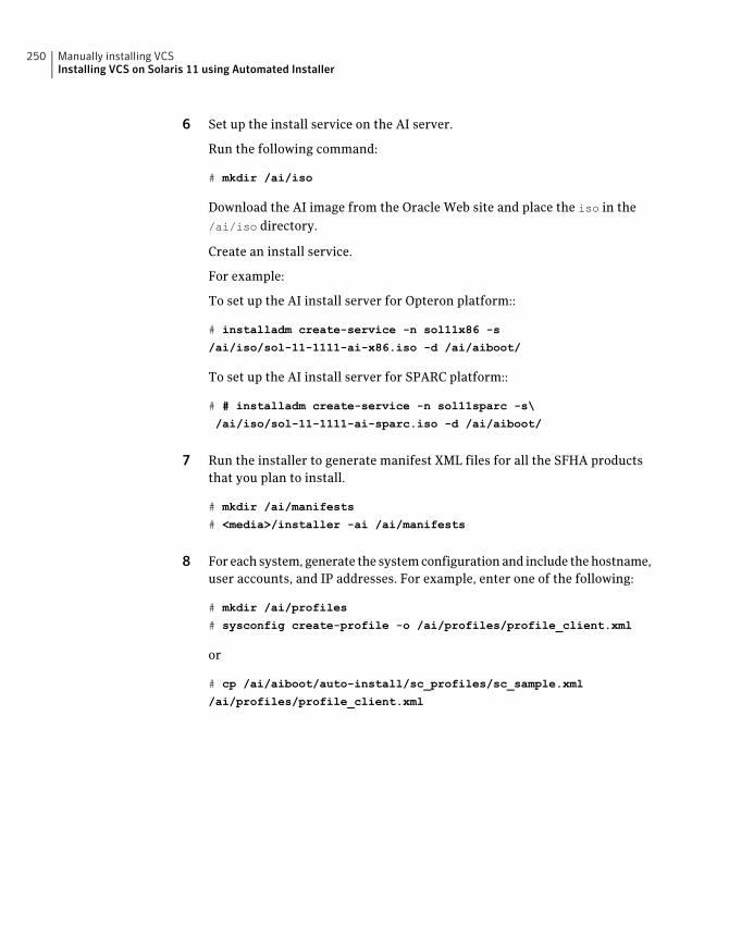
6 Set up the install service on the AI server.
Run the following command:
# mkdir /ai/iso
Download the AI image from the Oracle Web site and place the iso in the/ai/iso directory.
Create an install service.
For example:
To set up the AI install server for Opteron platform::
# installadm create-service -n sol11x86 -s
/ai/iso/sol-11-1111-ai-x86.iso -d /ai/aiboot/
To set up the AI install server for SPARC platform::
# # installadm create-service -n sol11sparc -s\
/ai/iso/sol-11-1111-ai-sparc.iso -d /ai/aiboot/
7 Run the installer to generate manifest XML files for all the SFHA productsthat you plan to install.
# mkdir /ai/manifests
# <media>/installer -ai /ai/manifests
8 For each system, generate the system configuration and include the hostname,user accounts, and IP addresses. For example, enter one of the following:
# mkdir /ai/profiles
# sysconfig create-profile -o /ai/profiles/profile_client.xml
or
# cp /ai/aiboot/auto-install/sc_profiles/sc_sample.xml
/ai/profiles/profile_client.xml
Manually installing VCSInstalling VCS on Solaris 11 using Automated Installer
250
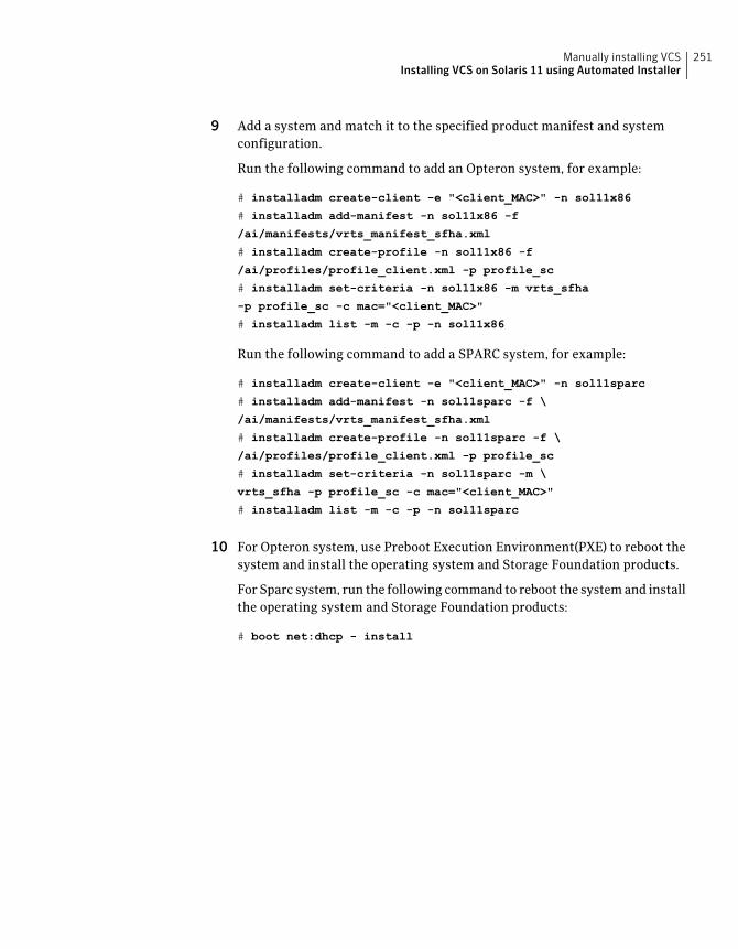
9 Add a system and match it to the specified product manifest and systemconfiguration.
Run the following command to add an Opteron system, for example:
# installadm create-client -e "<client_MAC>" -n sol11x86
# installadm add-manifest -n sol11x86 -f
/ai/manifests/vrts_manifest_sfha.xml
# installadm create-profile -n sol11x86 -f
/ai/profiles/profile_client.xml -p profile_sc
# installadm set-criteria -n sol11x86 -m vrts_sfha
-p profile_sc -c mac="<client_MAC>"
# installadm list -m -c -p -n sol11x86
Run the following command to add a SPARC system, for example:
# installadm create-client -e "<client_MAC>" -n sol11sparc
# installadm add-manifest -n sol11sparc -f \
/ai/manifests/vrts_manifest_sfha.xml
# installadm create-profile -n sol11sparc -f \
/ai/profiles/profile_client.xml -p profile_sc
# installadm set-criteria -n sol11sparc -m \
vrts_sfha -p profile_sc -c mac="<client_MAC>"
# installadm list -m -c -p -n sol11sparc
10 For Opteron system, use Preboot Execution Environment(PXE) to reboot thesystem and install the operating system and Storage Foundation products.
For Sparc system, run the following command to reboot the system and installthe operating system and Storage Foundation products:
# boot net:dhcp - install
251Manually installing VCSInstalling VCS on Solaris 11 using Automated Installer

Manually installing VCSInstalling VCS on Solaris 11 using Automated Installer
252
Manually configuring VCS
This chapter includes the following topics:
■ About configuring VCS manually
■ Configuring LLT manually
■ Configuring GAB manually
■ Configuring VCS manually
■ Configuring VCS in single node mode
■ Starting LLT, GAB, and VCS after manual configuration
■ Modifying the VCS configuration
About configuring VCS manuallyThis section describes the procedures to manually configure VCS.
Note: For manually configuring VCS in single node mode, you can skip steps aboutconfiguring LLT manually and configuring GAB manually.
Configuring LLT manuallyVCS uses the Low Latency Transport (LLT) protocol for all cluster communicationsas a high-performance, low-latency replacement for the IP stack. LLT has twomajor functions.
It handles the following tasks:
■ Traffic distribution
17Chapter
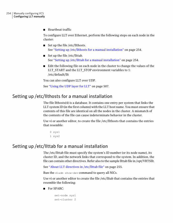
■ Heartbeat traffic
To configure LLT over Ethernet, perform the following steps on each node in thecluster:
■ Set up the file /etc/llthosts.See “Setting up /etc/llthosts for a manual installation” on page 254.
■ Set up the file /etc/llttab.See “Setting up /etc/llttab for a manual installation” on page 254.
■ Edit the following file on each node in the cluster to change the values of theLLT_START and the LLT_STOP environment variables to 1:/etc/default/llt
You can also configure LLT over UDP.
See “Using the UDP layer for LLT” on page 507.
Setting up /etc/llthosts for a manual installationThe file llthosts(4) is a database. It contains one entry per system that links theLLT system ID (in the first column) with the LLT host name. You must ensure thatcontents of this file are identical on all the nodes in the cluster. A mismatch ofthe contents of the file can cause indeterminate behavior in the cluster.
Use vi or another editor, to create the file /etc/llthosts that contains the entriesthat resemble:
0 sys1
1 sys2
Setting up /etc/llttab for a manual installationThe /etc/llttab file must specify the system’s ID number (or its node name), itscluster ID, and the network links that correspond to the system. In addition, thefile can contain other directives. Refer also to the sample llttab file in /opt/VRTSllt.
See “About LLT directives in /etc/llttab file” on page 255.
Run the dladm show-dev command to query all NICs.
Use vi or another editor to create the file /etc/lltab that contains the entries thatresemble the following:
■ For SPARC:
set-node sys1
set-cluster 2
Manually configuring VCSConfiguring LLT manually
254
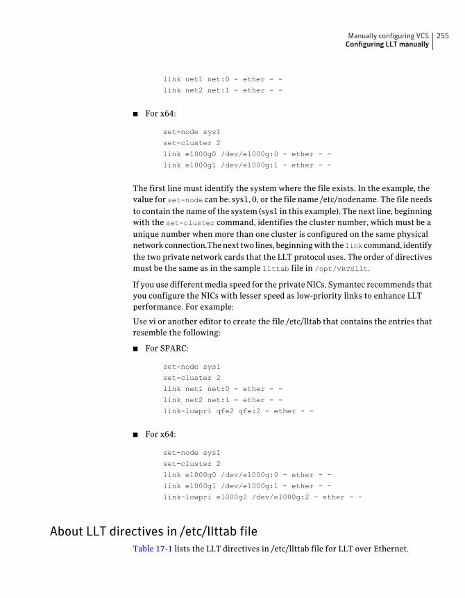
link net1 net:0 - ether - -
link net2 net:1 - ether - -
■ For x64:
set-node sys1
set-cluster 2
link e1000g0 /dev/e1000g:0 - ether - -
link e1000g1 /dev/e1000g:1 - ether - -
The first line must identify the system where the file exists. In the example, thevalue for set-node can be: sys1, 0, or the file name /etc/nodename. The file needsto contain the name of the system (sys1 in this example). The next line, beginningwith the set-cluster command, identifies the cluster number, which must be aunique number when more than one cluster is configured on the same physicalnetwork connection.The next two lines, beginning with thelink command, identifythe two private network cards that the LLT protocol uses. The order of directivesmust be the same as in the sample llttab file in /opt/VRTSllt.
If you use different media speed for the private NICs, Symantec recommends thatyou configure the NICs with lesser speed as low-priority links to enhance LLTperformance. For example:
Use vi or another editor to create the file /etc/lltab that contains the entries thatresemble the following:
■ For SPARC:
set-node sys1
set-cluster 2
link net1 net:0 - ether - -
link net2 net:1 - ether - -
link-lowpri qfe2 qfe:2 - ether - -
■ For x64:
set-node sys1
set-cluster 2
link e1000g0 /dev/e1000g:0 - ether - -
link e1000g1 /dev/e1000g:1 - ether - -
link-lowpri e1000g2 /dev/e1000g:2 - ether - -
About LLT directives in /etc/llttab fileTable 17-1 lists the LLT directives in /etc/llttab file for LLT over Ethernet.
255Manually configuring VCSConfiguring LLT manually
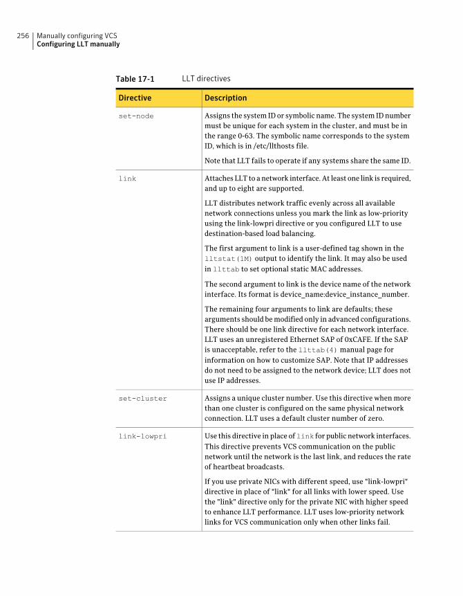
Table 17-1 LLT directives
DescriptionDirective
Assigns the system ID or symbolic name. The system ID numbermust be unique for each system in the cluster, and must be inthe range 0-63. The symbolic name corresponds to the systemID, which is in /etc/llthosts file.
Note that LLT fails to operate if any systems share the same ID.
set-node
Attaches LLT to a network interface. At least one link is required,and up to eight are supported.
LLT distributes network traffic evenly across all availablenetwork connections unless you mark the link as low-priorityusing the link-lowpri directive or you configured LLT to usedestination-based load balancing.
The first argument to link is a user-defined tag shown in thelltstat(1M) output to identify the link. It may also be usedin llttab to set optional static MAC addresses.
The second argument to link is the device name of the networkinterface. Its format is device_name:device_instance_number.
The remaining four arguments to link are defaults; thesearguments should be modified only in advanced configurations.There should be one link directive for each network interface.LLT uses an unregistered Ethernet SAP of 0xCAFE. If the SAPis unacceptable, refer to the llttab(4) manual page forinformation on how to customize SAP. Note that IP addressesdo not need to be assigned to the network device; LLT does notuse IP addresses.
link
Assigns a unique cluster number. Use this directive when morethan one cluster is configured on the same physical networkconnection. LLT uses a default cluster number of zero.
set-cluster
Use this directive in place oflink for public network interfaces.This directive prevents VCS communication on the publicnetwork until the network is the last link, and reduces the rateof heartbeat broadcasts.
If you use private NICs with different speed, use "link-lowpri"directive in place of "link" for all links with lower speed. Usethe "link" directive only for the private NIC with higher speedto enhance LLT performance. LLT uses low-priority networklinks for VCS communication only when other links fail.
link-lowpri
Manually configuring VCSConfiguring LLT manually
256
For more information about the LLT directives, refer to the llttab(4) manualpage.
Additional considerations for LLT for a manual installationYou must attach each network interface that is configured for LLT to a separateand distinct physical network.
By default, Oracle systems assign the same MAC address to all interfaces. Thus,connecting two or more interfaces to a network switch can cause problems.Consider the following example. You configure an IP on one public interface andLLT on another. Both interfaces are connected to a switch. The duplicate MACaddress on the two switch ports can cause the switch to incorrectly redirect IPtraffic to the LLT interface and vice versa. To avoid this issue, configure the systemto assign unique MAC addresses by setting the eeprom(1M) parameterlocal-mac-address? to true.
Configuring GAB manuallyVCS uses the Group Membership Services/Atomic Broadcast (GAB) protocol forcluster membership and reliable cluster communications. GAB has two majorfunctions.
It handles the following tasks:
■ Cluster membership
■ Cluster communications
257Manually configuring VCSConfiguring GAB manually
To configure GAB
1 Set up an /etc/gabtab configuration file on each node in the cluster using vior another editor. The following example shows an /etc/gabtab file:
/sbin/gabconfig -c -nN
Where the -c option configures the driver for use. The -nN option specifiesthat the cluster is not formed until at least N systems are ready to form thecluster. Symantec recommends that you set N to be the total number ofsystems in the cluster.
Warning: Symantec does not recommend the use of the -c -x option or -xoption for /sbin/gabconfig. Using -c -x or -x can lead to a split-braincondition.
2 Edit the following file on each node in the cluster to change the values of theGAB_START and the GAB_STOP environment variables to 1:
/etc/default/gab
Configuring VCS manuallyVCS configuration requires the types.cf and main.cf files on each system in thecluster. Both of the files are in the /etc/VRTSvcs/conf/config directory.
The main.cf configuration file requires the following minimumessential elements:
■ An "include" statement that specifies the file, types.cf, whichdefines the VCS bundled agent resource type definitions.
■ The name of the cluster.
■ The name of the systems that make up the cluster.
main.cf file
Note that the "include" statement in main.cf refers to the types.cf file.This text file describes the VCS bundled agent resource typedefinitions. During new installations, the types.cf file is automaticallycopied in to the /etc/VRTSvcs/conf/config directory.
types.cf file
When you manually install VCS, the file /etc/VRTSvcs/conf/config/main.cfcontains only the line:
include "types.cf"
Manually configuring VCSConfiguring VCS manually
258
For a full description of the main.cf file, and how to edit and verify it, refer to theVeritas Cluster Server Administrator's Guide.
To configure VCS manually
1 Log on as superuser, and move to the directory that contains the configurationfile:
# cd /etc/VRTSvcs/conf/config
2 Use vi or another text editor to edit the main.cf file, defining your clustername and system names. Refer to the following example.
An example main.cf for a two-node cluster:
include "types.cf"
cluster VCSCluster2 ( )
system sys1 ( )
system sys2 ( )
An example main.cf for a single-node cluster:
include "types.cf"
cluster VCSCluster1 ( )
system sn1 ( )
3 Save and close the main.cf file.
4 Edit the following file on each node in the cluster to change the values of theVCS_START and the VCS_STOP environment variables to 1:
/etc/default/vcs
Configuring the cluster UUID when creating a cluster manuallyYou need to configure the cluster UUID when you manually create a cluster.
To configure the cluster UUID when you create a cluster manually
◆ On one node in the cluster, perform the following command to populate thecluster UUID on each node in the cluster.
# /opt/VRTSvcs/bin/uuidconfig.pl -clus -configure nodeA
nodeB ... nodeN
Where nodeA, nodeB, through nodeN are the names of the cluster nodes.
259Manually configuring VCSConfiguring VCS manually
Configuring VCS in single node modeIn addition to the steps mentioned in the manual configuration section, completethe following steps to configure VCS in single node mode.
See “Configuring VCS manually” on page 258.
To configure VCS in single node mode
1 Disable the VCS SMF service imported by VRTSvcs package.
# svcadm disable -s system/vcs:default
2 Delete the VCS SMF service configuration.
# svccfg delete -f system/vcs:default
3 Edit the following file to change the value of the ONENODE environmentvariable to yes.
/etc/default/vcs
4 Import the SMF service for vcs-onenode.
# svccfg import /etc/VRTSvcs/conf/vcs-onenode.xml
Starting LLT,GAB, andVCSaftermanual configurationAfter you have configured LLT, GAB, and VCS, use the following procedures tostart LLT, GAB, and VCS.
To start LLT
1 On each node, run the following command to start LLT:
# svcadm enable llt
If LLT is configured correctly on each node, the console output resembles:
Jun 26 19:04:24 sys1 kernel: [1571667.550527] LLT INFO V-14-1-10009 LLT 6.0.100.000-SBLD Protocol available
2 On each node, run the following command to verify that LLT is running:
# /sbin/lltconfig
LLT is running
Manually configuring VCSConfiguring VCS in single node mode
260
To start GAB
1 On each node, run the following command to start GAB:
# svcadm enable gab
If GAB is configured correctly on each node, the console output resembles:
Jun 26 19:10:34 sys1 kernel: [1572037.501731] GAB INFO
V-15-1-20021 GAB 6.0.100.000-SBLD available
2 On each node, run the following command to verify that GAB is running:
# /sbin/gabconfig -a
GAB Port Memberships
===================================
Port a gen a36e0003 membership 01
To start VCS
◆ On each node, type:
# svcadm enable vcs
If VCS is configured correctly on each node, the console output resembles:
Apr 5 14:52:02 sys1 gab: GAB:20036: Port h gen 3972a201
membership 01
See “Verifying the cluster” on page 379.
To start VCS as single node
◆ Run the following command:
# svcadm enable vcs-onenode
Modifying the VCS configurationAfter the successful installation of VCS, you can modify the configuration of VCSusing several methods. You can dynamically modify the configuration from thecommand line, Veritas Operations Manager, or the Cluster Manager (Java Console).For information on management tools, refer to the Veritas Cluster ServerAdministrator’s Guide.
261Manually configuring VCSModifying the VCS configuration
You can also edit the main.cf file directly. For information on the structure of themain.cf file, refer to the Veritas Cluster Server Administrator’s Guide.
Configuring the ClusterService groupWhen you have installed VCS, and verified that LLT, GAB, and VCS work, you cancreate a service group to include the optional features. These features include theVCS notification components and the Global Cluster option. If you manually addedVCS to your cluster systems, you must manually create the ClusterService group.You can refer to the configuration examples of a system with a ClusterServicegroup. See theVeritasClusterServerAdministrator'sGuide for more information.
See “Sample main.cf file for VCS clusters” on page 491.
Manually configuring VCSModifying the VCS configuration
262
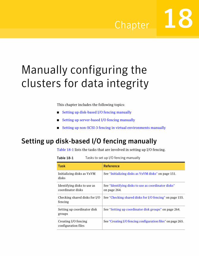
Manually configuring theclusters for data integrity
This chapter includes the following topics:
■ Setting up disk-based I/O fencing manually
■ Setting up server-based I/O fencing manually
■ Setting up non-SCSI-3 fencing in virtual environments manually
Setting up disk-based I/O fencing manuallyTable 18-1 lists the tasks that are involved in setting up I/O fencing.
Table 18-1 Tasks to set up I/O fencing manually
ReferenceTask
See “Initializing disks as VxVM disks” on page 151.Initializing disks as VxVMdisks
See “Identifying disks to use as coordinator disks”on page 264.
Identifying disks to use ascoordinator disks
See “Checking shared disks for I/O fencing” on page 155.Checking shared disks for I/Ofencing
See “Setting up coordinator disk groups” on page 264.Setting up coordinator diskgroups
See “Creating I/O fencing configuration files” on page 265.Creating I/O fencingconfiguration files
18Chapter
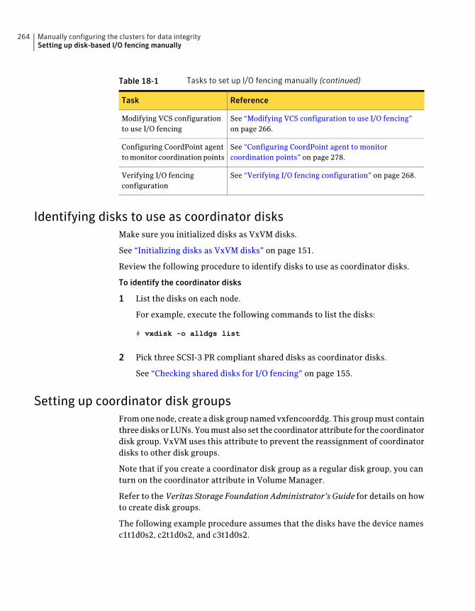
Table 18-1 Tasks to set up I/O fencing manually (continued)
ReferenceTask
See “Modifying VCS configuration to use I/O fencing”on page 266.
Modifying VCS configurationto use I/O fencing
See “Configuring CoordPoint agent to monitorcoordination points” on page 278.
Configuring CoordPoint agentto monitor coordination points
See “Verifying I/O fencing configuration” on page 268.Verifying I/O fencingconfiguration
Identifying disks to use as coordinator disksMake sure you initialized disks as VxVM disks.
See “Initializing disks as VxVM disks” on page 151.
Review the following procedure to identify disks to use as coordinator disks.
To identify the coordinator disks
1 List the disks on each node.
For example, execute the following commands to list the disks:
# vxdisk -o alldgs list
2 Pick three SCSI-3 PR compliant shared disks as coordinator disks.
See “Checking shared disks for I/O fencing” on page 155.
Setting up coordinator disk groupsFrom one node, create a disk group named vxfencoorddg. This group must containthree disks or LUNs. You must also set the coordinator attribute for the coordinatordisk group. VxVM uses this attribute to prevent the reassignment of coordinatordisks to other disk groups.
Note that if you create a coordinator disk group as a regular disk group, you canturn on the coordinator attribute in Volume Manager.
Refer to the Veritas Storage Foundation Administrator’s Guide for details on howto create disk groups.
The following example procedure assumes that the disks have the device namesc1t1d0s2, c2t1d0s2, and c3t1d0s2.
Manually configuring the clusters for data integritySetting up disk-based I/O fencing manually
264
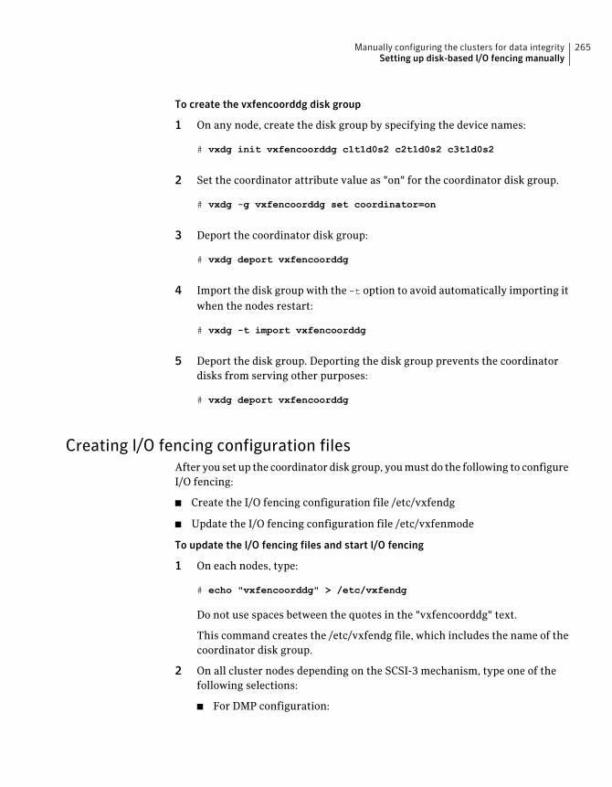
To create the vxfencoorddg disk group
1 On any node, create the disk group by specifying the device names:
# vxdg init vxfencoorddg c1t1d0s2 c2t1d0s2 c3t1d0s2
2 Set the coordinator attribute value as "on" for the coordinator disk group.
# vxdg -g vxfencoorddg set coordinator=on
3 Deport the coordinator disk group:
# vxdg deport vxfencoorddg
4 Import the disk group with the -t option to avoid automatically importing itwhen the nodes restart:
# vxdg -t import vxfencoorddg
5 Deport the disk group. Deporting the disk group prevents the coordinatordisks from serving other purposes:
# vxdg deport vxfencoorddg
Creating I/O fencing configuration filesAfter you set up the coordinator disk group, you must do the following to configureI/O fencing:
■ Create the I/O fencing configuration file /etc/vxfendg
■ Update the I/O fencing configuration file /etc/vxfenmode
To update the I/O fencing files and start I/O fencing
1 On each nodes, type:
# echo "vxfencoorddg" > /etc/vxfendg
Do not use spaces between the quotes in the "vxfencoorddg" text.
This command creates the /etc/vxfendg file, which includes the name of thecoordinator disk group.
2 On all cluster nodes depending on the SCSI-3 mechanism, type one of thefollowing selections:
■ For DMP configuration:
265Manually configuring the clusters for data integritySetting up disk-based I/O fencing manually
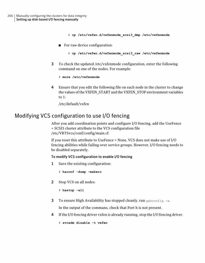
# cp /etc/vxfen.d/vxfenmode_scsi3_dmp /etc/vxfenmode
■ For raw device configuration:
# cp /etc/vxfen.d/vxfenmode_scsi3_raw /etc/vxfenmode
3 To check the updated /etc/vxfenmode configuration, enter the followingcommand on one of the nodes. For example:
# more /etc/vxfenmode
4 Ensure that you edit the following file on each node in the cluster to changethe values of the VXFEN_START and the VXFEN_STOP environment variablesto 1:
/etc/default/vxfen
Modifying VCS configuration to use I/O fencingAfter you add coordination points and configure I/O fencing, add the UseFence= SCSI3 cluster attribute to the VCS configuration file/etc/VRTSvcs/conf/config/main.cf.
If you reset this attribute to UseFence = None, VCS does not make use of I/Ofencing abilities while failing over service groups. However, I/O fencing needs tobe disabled separately.
To modify VCS configuration to enable I/O fencing
1 Save the existing configuration:
# haconf -dump -makero
2 Stop VCS on all nodes:
# hastop -all
3 To ensure High Availability has stopped cleanly, run gabconfig -a.
In the output of the commans, check that Port h is not present.
4 If the I/O fencing driver vxfen is already running, stop the I/O fencing driver.
# svcadm disable -t vxfen
Manually configuring the clusters for data integritySetting up disk-based I/O fencing manually
266
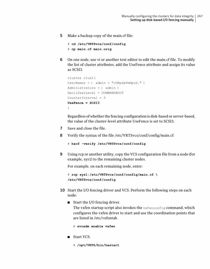
5 Make a backup copy of the main.cf file:
# cd /etc/VRTSvcs/conf/config
# cp main.cf main.orig
6 On one node, use vi or another text editor to edit the main.cf file. To modifythe list of cluster attributes, add the UseFence attribute and assign its valueas SCSI3.
cluster clus1(
UserNames = { admin = "cDRpdxPmHpzS." }
Administrators = { admin }
HacliUserLevel = COMMANDROOT
CounterInterval = 5
UseFence = SCSI3
)
Regardless of whether the fencing configuration is disk-based or server-based,the value of the cluster-level attribute UseFence is set to SCSI3.
7 Save and close the file.
8 Verify the syntax of the file /etc/VRTSvcs/conf/config/main.cf:
# hacf -verify /etc/VRTSvcs/conf/config
9 Using rcp or another utility, copy the VCS configuration file from a node (forexample, sys1) to the remaining cluster nodes.
For example, on each remaining node, enter:
# rcp sys1:/etc/VRTSvcs/conf/config/main.cf \
/etc/VRTSvcs/conf/config
10 Start the I/O fencing driver and VCS. Perform the following steps on eachnode:
■ Start the I/O fencing driver.The vxfen startup script also invokes the vxfenconfig command, whichconfigures the vxfen driver to start and use the coordination points thatare listed in /etc/vxfentab.
# svcadm enable vxfen
■ Start VCS.
# /opt/VRTS/bin/hastart
267Manually configuring the clusters for data integritySetting up disk-based I/O fencing manually
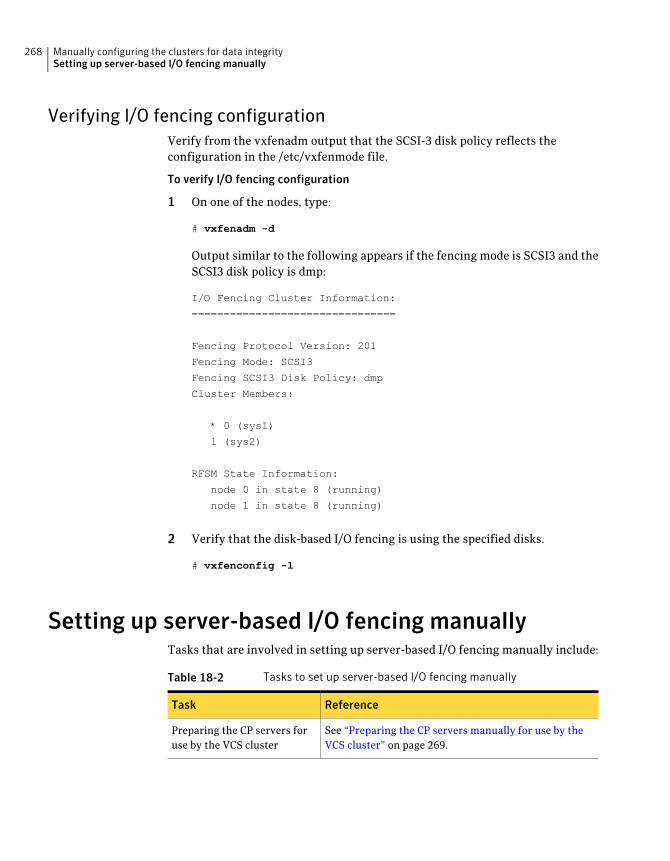
Verifying I/O fencing configurationVerify from the vxfenadm output that the SCSI-3 disk policy reflects theconfiguration in the /etc/vxfenmode file.
To verify I/O fencing configuration
1 On one of the nodes, type:
# vxfenadm -d
Output similar to the following appears if the fencing mode is SCSI3 and theSCSI3 disk policy is dmp:
I/O Fencing Cluster Information:
================================
Fencing Protocol Version: 201
Fencing Mode: SCSI3
Fencing SCSI3 Disk Policy: dmp
Cluster Members:
* 0 (sys1)
1 (sys2)
RFSM State Information:
node 0 in state 8 (running)
node 1 in state 8 (running)
2 Verify that the disk-based I/O fencing is using the specified disks.
# vxfenconfig -l
Setting up server-based I/O fencing manuallyTasks that are involved in setting up server-based I/O fencing manually include:
Table 18-2 Tasks to set up server-based I/O fencing manually
ReferenceTask
See “Preparing the CP servers manually for use by theVCS cluster” on page 269.
Preparing the CP servers foruse by the VCS cluster
Manually configuring the clusters for data integritySetting up server-based I/O fencing manually
268
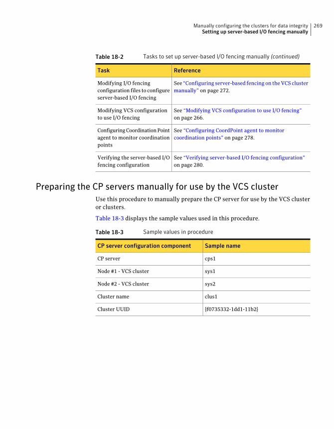
Table 18-2 Tasks to set up server-based I/O fencing manually (continued)
ReferenceTask
See “Configuring server-based fencing on the VCS clustermanually” on page 272.
Modifying I/O fencingconfiguration files to configureserver-based I/O fencing
See “Modifying VCS configuration to use I/O fencing”on page 266.
Modifying VCS configurationto use I/O fencing
See “Configuring CoordPoint agent to monitorcoordination points” on page 278.
Configuring Coordination Pointagent to monitor coordinationpoints
See “Verifying server-based I/O fencing configuration”on page 280.
Verifying the server-based I/Ofencing configuration
Preparing the CP servers manually for use by the VCS clusterUse this procedure to manually prepare the CP server for use by the VCS clusteror clusters.
Table 18-3 displays the sample values used in this procedure.
Table 18-3 Sample values in procedure
Sample nameCP server configuration component
cps1CP server
sys1Node #1 - VCS cluster
sys2Node #2 - VCS cluster
clus1Cluster name
{f0735332-1dd1-11b2}Cluster UUID
269Manually configuring the clusters for data integritySetting up server-based I/O fencing manually
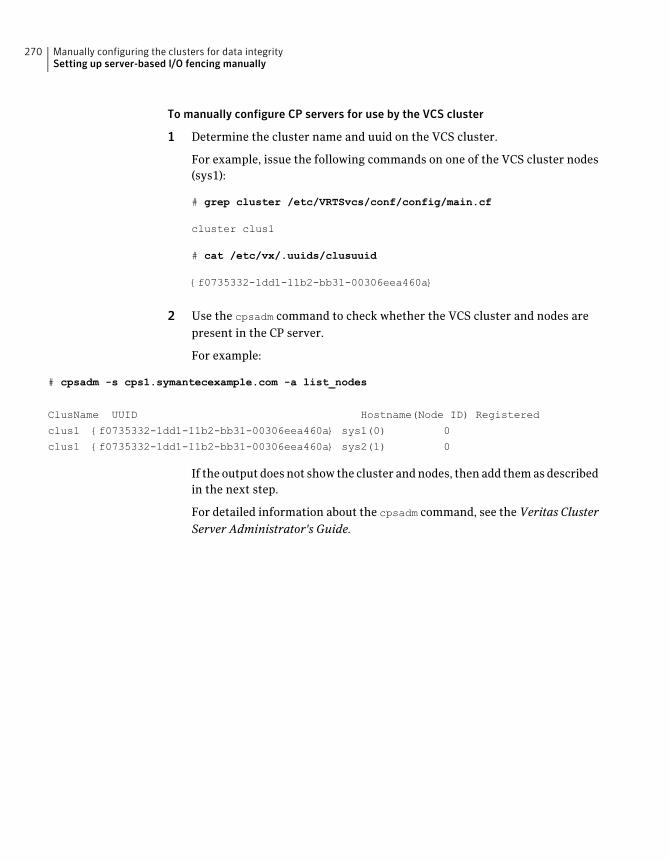
To manually configure CP servers for use by the VCS cluster
1 Determine the cluster name and uuid on the VCS cluster.
For example, issue the following commands on one of the VCS cluster nodes(sys1):
# grep cluster /etc/VRTSvcs/conf/config/main.cf
cluster clus1
# cat /etc/vx/.uuids/clusuuid
{f0735332-1dd1-11b2-bb31-00306eea460a}
2 Use the cpsadm command to check whether the VCS cluster and nodes arepresent in the CP server.
For example:
# cpsadm -s cps1.symantecexample.com -a list_nodes
ClusName UUID Hostname(Node ID) Registered
clus1 {f0735332-1dd1-11b2-bb31-00306eea460a} sys1(0) 0
clus1 {f0735332-1dd1-11b2-bb31-00306eea460a} sys2(1) 0
If the output does not show the cluster and nodes, then add them as describedin the next step.
For detailed information about the cpsadm command, see the Veritas ClusterServer Administrator's Guide.
Manually configuring the clusters for data integritySetting up server-based I/O fencing manually
270
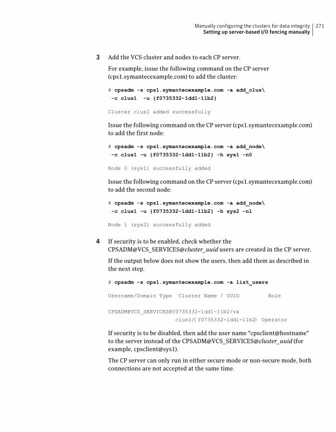
3 Add the VCS cluster and nodes to each CP server.
For example, issue the following command on the CP server(cps1.symantecexample.com) to add the cluster:
# cpsadm -s cps1.symantecexample.com -a add_clus\
-c clus1 -u {f0735332-1dd1-11b2}
Cluster clus1 added successfully
Issue the following command on the CP server (cps1.symantecexample.com)to add the first node:
# cpsadm -s cps1.symantecexample.com -a add_node\
-c clus1 -u {f0735332-1dd1-11b2} -h sys1 -n0
Node 0 (sys1) successfully added
Issue the following command on the CP server (cps1.symantecexample.com)to add the second node:
# cpsadm -s cps1.symantecexample.com -a add_node\
-c clus1 -u {f0735332-1dd1-11b2} -h sys2 -n1
Node 1 (sys2) successfully added
4 If security is to be enabled, check whether theCPSADM@VCS_SERVICES@cluster_uuid users are created in the CP server.
If the output below does not show the users, then add them as described inthe next step.
# cpsadm -s cps1.symantecexample.com -a list_users
Username/Domain Type Cluster Name / UUID Role
CPSADM@VCS_SERVICES@f0735332-1dd1-11b2/vx
clus1/{f0735332-1dd1-11b2} Operator
If security is to be disabled, then add the user name "cpsclient@hostname"to the server instead of the CPSADM@VCS_SERVICES@cluster_uuid (forexample, cpsclient@sys1).
The CP server can only run in either secure mode or non-secure mode, bothconnections are not accepted at the same time.
271Manually configuring the clusters for data integritySetting up server-based I/O fencing manually
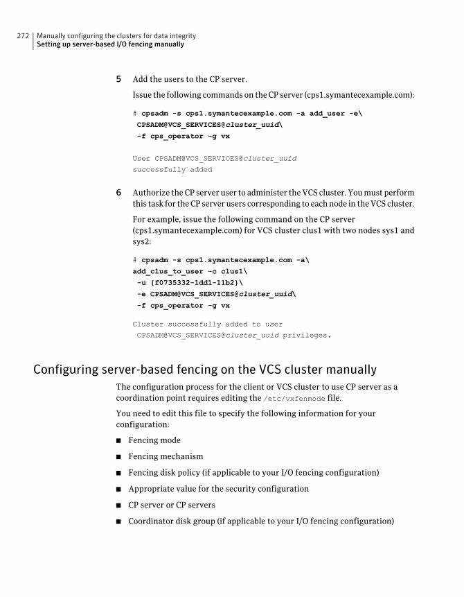
5 Add the users to the CP server.
Issue the following commands on the CP server (cps1.symantecexample.com):
# cpsadm -s cps1.symantecexample.com -a add_user -e\
CPSADM@VCS_SERVICES@cluster_uuid\
-f cps_operator -g vx
User CPSADM@VCS_SERVICES@cluster_uuid
successfully added
6 Authorize the CP server user to administer the VCS cluster. You must performthis task for the CP server users corresponding to each node in the VCS cluster.
For example, issue the following command on the CP server(cps1.symantecexample.com) for VCS cluster clus1 with two nodes sys1 andsys2:
# cpsadm -s cps1.symantecexample.com -a\
add_clus_to_user -c clus1\
-u {f0735332-1dd1-11b2}\
-e CPSADM@VCS_SERVICES@cluster_uuid\
-f cps_operator -g vx
Cluster successfully added to user
CPSADM@VCS_SERVICES@cluster_uuid privileges.
Configuring server-based fencing on the VCS cluster manuallyThe configuration process for the client or VCS cluster to use CP server as acoordination point requires editing the /etc/vxfenmode file.
You need to edit this file to specify the following information for yourconfiguration:
■ Fencing mode
■ Fencing mechanism
■ Fencing disk policy (if applicable to your I/O fencing configuration)
■ Appropriate value for the security configuration
■ CP server or CP servers
■ Coordinator disk group (if applicable to your I/O fencing configuration)
Manually configuring the clusters for data integritySetting up server-based I/O fencing manually
272
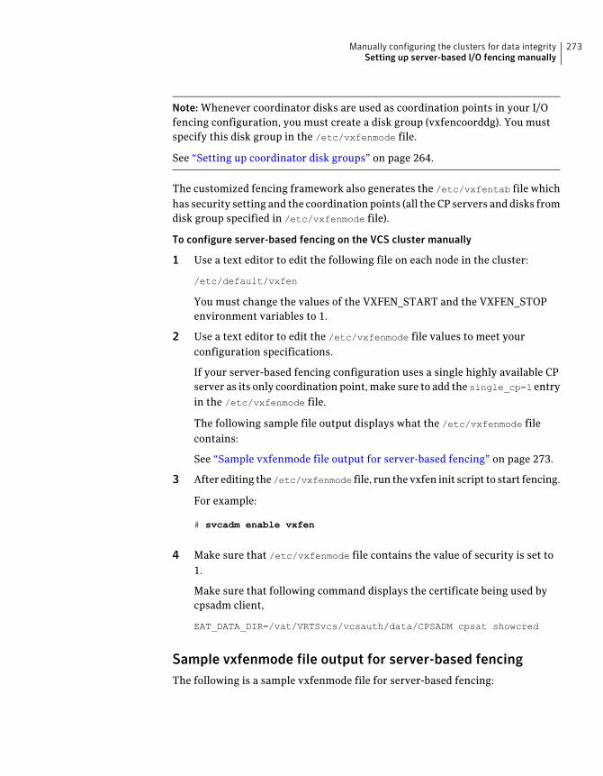
Note: Whenever coordinator disks are used as coordination points in your I/Ofencing configuration, you must create a disk group (vxfencoorddg). You mustspecify this disk group in the /etc/vxfenmode file.
See “Setting up coordinator disk groups” on page 264.
The customized fencing framework also generates the /etc/vxfentab file whichhas security setting and the coordination points (all the CP servers and disks fromdisk group specified in /etc/vxfenmode file).
To configure server-based fencing on the VCS cluster manually
1 Use a text editor to edit the following file on each node in the cluster:
/etc/default/vxfen
You must change the values of the VXFEN_START and the VXFEN_STOPenvironment variables to 1.
2 Use a text editor to edit the /etc/vxfenmode file values to meet yourconfiguration specifications.
If your server-based fencing configuration uses a single highly available CPserver as its only coordination point, make sure to add the single_cp=1 entryin the /etc/vxfenmode file.
The following sample file output displays what the /etc/vxfenmode filecontains:
See “Sample vxfenmode file output for server-based fencing” on page 273.
3 After editing the/etc/vxfenmode file, run the vxfen init script to start fencing.
For example:
# svcadm enable vxfen
4 Make sure that /etc/vxfenmode file contains the value of security is set to1.
Make sure that following command displays the certificate being used bycpsadm client,
EAT_DATA_DIR=/vat/VRTSvcs/vcsauth/data/CPSADM cpsat showcred
Sample vxfenmode file output for server-based fencingThe following is a sample vxfenmode file for server-based fencing:
273Manually configuring the clusters for data integritySetting up server-based I/O fencing manually
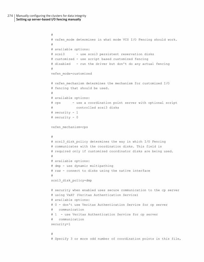
#
# vxfen_mode determines in what mode VCS I/O Fencing should work.
#
# available options:
# scsi3 - use scsi3 persistent reservation disks
# customized - use script based customized fencing
# disabled - run the driver but don't do any actual fencing
#
vxfen_mode=customized
# vxfen_mechanism determines the mechanism for customized I/O
# fencing that should be used.
#
# available options:
# cps - use a coordination point server with optional script
# controlled scsi3 disks
# security - 1
# security - 0
vxfen_mechanism=cps
#
# scsi3_disk_policy determines the way in which I/O Fencing
# communicates with the coordination disks. This field is
# required only if customized coordinator disks are being used.
#
# available options:
# dmp - use dynamic multipathing
# raw - connect to disks using the native interface
#
scsi3_disk_policy=dmp
# security when enabled uses secure communication to the cp server
# using VxAT (Veritas Authentication Service)
# available options:
# 0 - don't use Veritas Authentication Service for cp server
# communication
# 1 - use Veritas Authentication Service for cp server
# communication
security=1
#
# Specify 3 or more odd number of coordination points in this file,
Manually configuring the clusters for data integritySetting up server-based I/O fencing manually
274
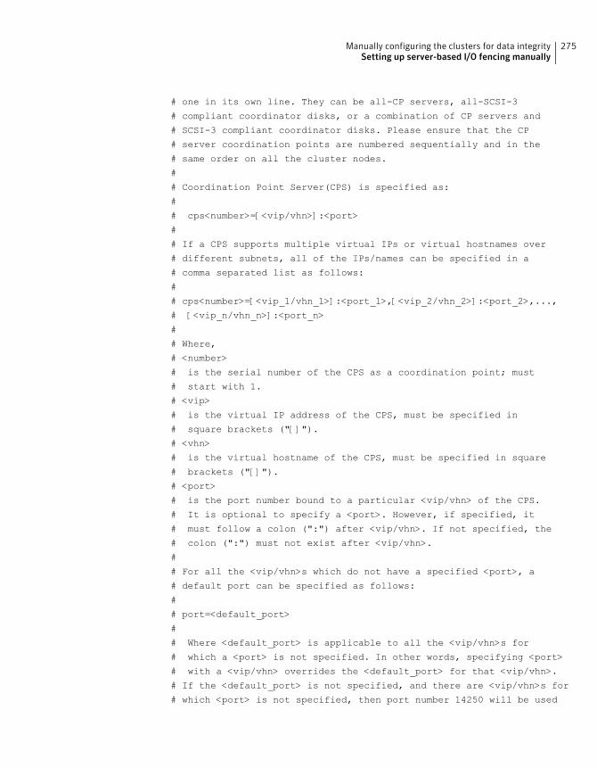
# one in its own line. They can be all-CP servers, all-SCSI-3
# compliant coordinator disks, or a combination of CP servers and
# SCSI-3 compliant coordinator disks. Please ensure that the CP
# server coordination points are numbered sequentially and in the
# same order on all the cluster nodes.
#
# Coordination Point Server(CPS) is specified as:
#
# cps<number>=[<vip/vhn>]:<port>
#
# If a CPS supports multiple virtual IPs or virtual hostnames over
# different subnets, all of the IPs/names can be specified in a
# comma separated list as follows:
#
# cps<number>=[<vip_1/vhn_1>]:<port_1>,[<vip_2/vhn_2>]:<port_2>,...,
# [<vip_n/vhn_n>]:<port_n>
#
# Where,
# <number>
# is the serial number of the CPS as a coordination point; must
# start with 1.
# <vip>
# is the virtual IP address of the CPS, must be specified in
# square brackets ("[]").
# <vhn>
# is the virtual hostname of the CPS, must be specified in square
# brackets ("[]").
# <port>
# is the port number bound to a particular <vip/vhn> of the CPS.
# It is optional to specify a <port>. However, if specified, it
# must follow a colon (":") after <vip/vhn>. If not specified, the
# colon (":") must not exist after <vip/vhn>.
#
# For all the <vip/vhn>s which do not have a specified <port>, a
# default port can be specified as follows:
#
# port=<default_port>
#
# Where <default_port> is applicable to all the <vip/vhn>s for
# which a <port> is not specified. In other words, specifying <port>
# with a <vip/vhn> overrides the <default_port> for that <vip/vhn>.
# If the <default_port> is not specified, and there are <vip/vhn>s for
# which <port> is not specified, then port number 14250 will be used
275Manually configuring the clusters for data integritySetting up server-based I/O fencing manually
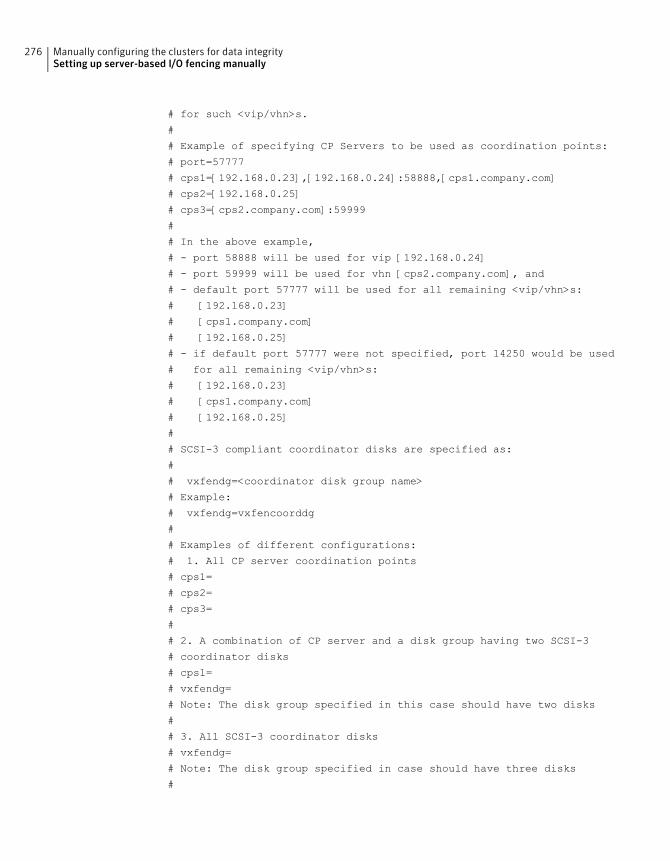
# for such <vip/vhn>s.
#
# Example of specifying CP Servers to be used as coordination points:
# port=57777
# cps1=[192.168.0.23],[192.168.0.24]:58888,[cps1.company.com]
# cps2=[192.168.0.25]
# cps3=[cps2.company.com]:59999
#
# In the above example,
# - port 58888 will be used for vip [192.168.0.24]
# - port 59999 will be used for vhn [cps2.company.com], and
# - default port 57777 will be used for all remaining <vip/vhn>s:
# [192.168.0.23]
# [cps1.company.com]
# [192.168.0.25]
# - if default port 57777 were not specified, port 14250 would be used
# for all remaining <vip/vhn>s:
# [192.168.0.23]
# [cps1.company.com]
# [192.168.0.25]
#
# SCSI-3 compliant coordinator disks are specified as:
#
# vxfendg=<coordinator disk group name>
# Example:
# vxfendg=vxfencoorddg
#
# Examples of different configurations:
# 1. All CP server coordination points
# cps1=
# cps2=
# cps3=
#
# 2. A combination of CP server and a disk group having two SCSI-3
# coordinator disks
# cps1=
# vxfendg=
# Note: The disk group specified in this case should have two disks
#
# 3. All SCSI-3 coordinator disks
# vxfendg=
# Note: The disk group specified in case should have three disks
#
Manually configuring the clusters for data integritySetting up server-based I/O fencing manually
276
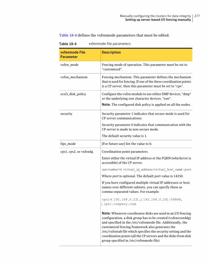
Table 18-4 defines the vxfenmode parameters that must be edited.
Table 18-4 vxfenmode file parameters
Descriptionvxfenmode FileParameter
Fencing mode of operation. This parameter must be set to“customized”.
vxfen_mode
Fencing mechanism. This parameter defines the mechanismthat is used for fencing. If one of the three coordination pointsis a CP server, then this parameter must be set to “cps”.
vxfen_mechanism
Configure the vxfen module to use either DMP devices, "dmp"or the underlying raw character devices, "raw".
Note: The configured disk policy is applied on all the nodes.
scsi3_disk_policy
Security parameter 1 indicates that secure mode is used forCP server communications.
Security parameter 0 indicates that communication with theCP server is made in non-secure mode.
The default security value is 1.
security
[For future use] Set the value to 0.fips_mode
Coordination point parameters.
Enter either the virtual IP address or the FQHN (whichever isaccessible) of the CP server.
cps<number>=[virtual_ip_address/virtual_host_name]:port
Where port is optional. The default port value is 14250.
If you have configured multiple virtual IP addresses or hostnames over different subnets, you can specify these ascomma-separated values. For example:
cps1=[192.168.0.23],[192.168.0.24]:58888,[cps1.company.com]
Note: Whenever coordinator disks are used in an I/O fencingconfiguration, a disk group has to be created (vxfencoorddg)and specified in the /etc/vxfenmode file. Additionally, thecustomized fencing framework also generates the/etc/vxfentab file which specifies the security setting and thecoordination points (all the CP servers and the disks from diskgroup specified in /etc/vxfenmode file).
cps1, cps2, or vxfendg
277Manually configuring the clusters for data integritySetting up server-based I/O fencing manually
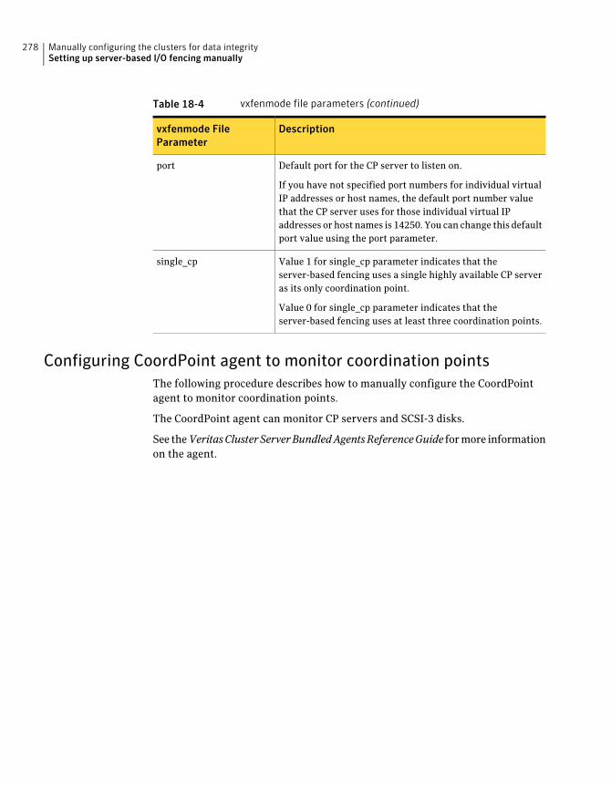
Table 18-4 vxfenmode file parameters (continued)
Descriptionvxfenmode FileParameter
Default port for the CP server to listen on.
If you have not specified port numbers for individual virtualIP addresses or host names, the default port number valuethat the CP server uses for those individual virtual IPaddresses or host names is 14250. You can change this defaultport value using the port parameter.
port
Value 1 for single_cp parameter indicates that theserver-based fencing uses a single highly available CP serveras its only coordination point.
Value 0 for single_cp parameter indicates that theserver-based fencing uses at least three coordination points.
single_cp
Configuring CoordPoint agent to monitor coordination pointsThe following procedure describes how to manually configure the CoordPointagent to monitor coordination points.
The CoordPoint agent can monitor CP servers and SCSI-3 disks.
See theVeritasClusterServerBundledAgentsReferenceGuide for more informationon the agent.
Manually configuring the clusters for data integritySetting up server-based I/O fencing manually
278
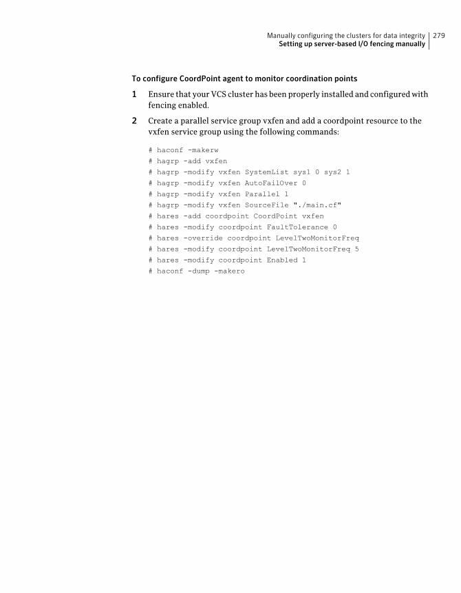
To configure CoordPoint agent to monitor coordination points
1 Ensure that your VCS cluster has been properly installed and configured withfencing enabled.
2 Create a parallel service group vxfen and add a coordpoint resource to thevxfen service group using the following commands:
# haconf -makerw
# hagrp -add vxfen
# hagrp -modify vxfen SystemList sys1 0 sys2 1
# hagrp -modify vxfen AutoFailOver 0
# hagrp -modify vxfen Parallel 1
# hagrp -modify vxfen SourceFile "./main.cf"
# hares -add coordpoint CoordPoint vxfen
# hares -modify coordpoint FaultTolerance 0
# hares -override coordpoint LevelTwoMonitorFreq
# hares -modify coordpoint LevelTwoMonitorFreq 5
# hares -modify coordpoint Enabled 1
# haconf -dump -makero
279Manually configuring the clusters for data integritySetting up server-based I/O fencing manually
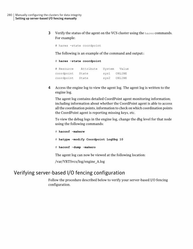
3 Verify the status of the agent on the VCS cluster using the hares commands.For example:
# hares -state coordpoint
The following is an example of the command and output::
# hares -state coordpoint
# Resource Attribute System Value
coordpoint State sys1 ONLINE
coordpoint State sys2 ONLINE
4 Access the engine log to view the agent log. The agent log is written to theengine log.
The agent log contains detailed CoordPoint agent monitoring information;including information about whether the CoordPoint agent is able to accessall the coordination points, information to check on which coordination pointsthe CoordPoint agent is reporting missing keys, etc.
To view the debug logs in the engine log, change the dbg level for that nodeusing the following commands:
# haconf -makerw
# hatype -modify Coordpoint LogDbg 10
# haconf -dump -makero
The agent log can now be viewed at the following location:
/var/VRTSvcs/log/engine_A.log
Verifying server-based I/O fencing configurationFollow the procedure described below to verify your server-based I/O fencingconfiguration.
Manually configuring the clusters for data integritySetting up server-based I/O fencing manually
280
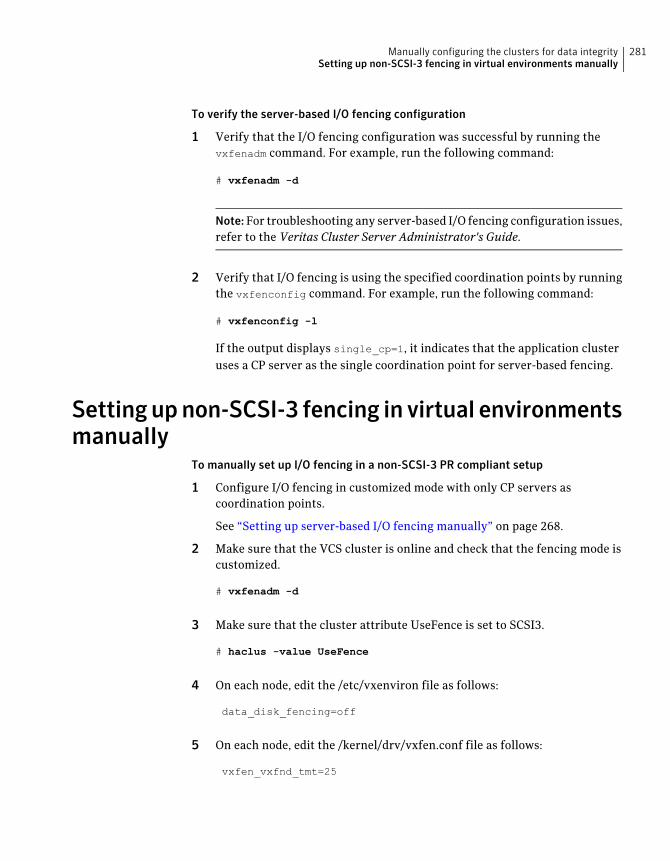
To verify the server-based I/O fencing configuration
1 Verify that the I/O fencing configuration was successful by running thevxfenadm command. For example, run the following command:
# vxfenadm -d
Note: For troubleshooting any server-based I/O fencing configuration issues,refer to the Veritas Cluster Server Administrator's Guide.
2 Verify that I/O fencing is using the specified coordination points by runningthe vxfenconfig command. For example, run the following command:
# vxfenconfig -l
If the output displays single_cp=1, it indicates that the application clusteruses a CP server as the single coordination point for server-based fencing.
Setting upnon-SCSI-3 fencing in virtual environmentsmanually
To manually set up I/O fencing in a non-SCSI-3 PR compliant setup
1 Configure I/O fencing in customized mode with only CP servers ascoordination points.
See “Setting up server-based I/O fencing manually” on page 268.
2 Make sure that the VCS cluster is online and check that the fencing mode iscustomized.
# vxfenadm -d
3 Make sure that the cluster attribute UseFence is set to SCSI3.
# haclus -value UseFence
4 On each node, edit the /etc/vxenviron file as follows:
data_disk_fencing=off
5 On each node, edit the /kernel/drv/vxfen.conf file as follows:
vxfen_vxfnd_tmt=25
281Manually configuring the clusters for data integritySetting up non-SCSI-3 fencing in virtual environments manually
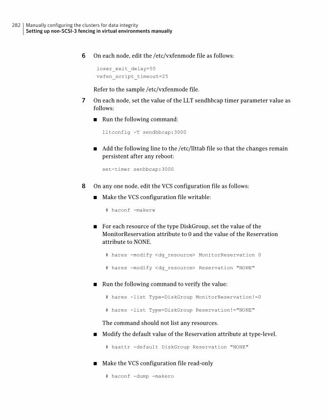
6 On each node, edit the /etc/vxfenmode file as follows:
loser_exit_delay=55
vxfen_script_timeout=25
Refer to the sample /etc/vxfenmode file.
7 On each node, set the value of the LLT sendhbcap timer parameter value asfollows:
■ Run the following command:
lltconfig -T sendhbcap:3000
■ Add the following line to the /etc/llttab file so that the changes remainpersistent after any reboot:
set-timer senhbcap:3000
8 On any one node, edit the VCS configuration file as follows:
■ Make the VCS configuration file writable:
# haconf -makerw
■ For each resource of the type DiskGroup, set the value of theMonitorReservation attribute to 0 and the value of the Reservationattribute to NONE.
# hares -modify <dg_resource> MonitorReservation 0
# hares -modify <dg_resource> Reservation "NONE"
■ Run the following command to verify the value:
# hares -list Type=DiskGroup MonitorReservation!=0
# hares -list Type=DiskGroup Reservation!="NONE"
The command should not list any resources.
■ Modify the default value of the Reservation attribute at type-level.
# haattr -default DiskGroup Reservation "NONE"
■ Make the VCS configuration file read-only
# haconf -dump -makero
Manually configuring the clusters for data integritySetting up non-SCSI-3 fencing in virtual environments manually
282
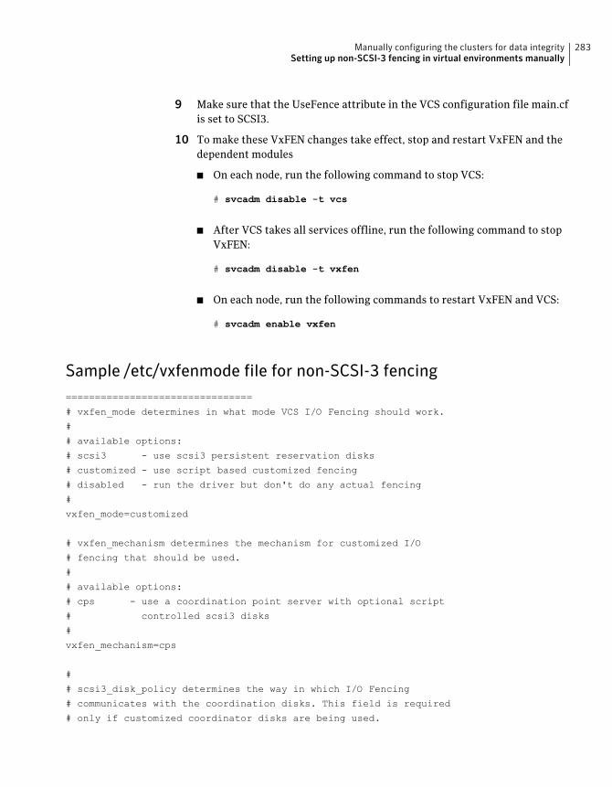
9 Make sure that the UseFence attribute in the VCS configuration file main.cfis set to SCSI3.
10 To make these VxFEN changes take effect, stop and restart VxFEN and thedependent modules
■ On each node, run the following command to stop VCS:
# svcadm disable -t vcs
■ After VCS takes all services offline, run the following command to stopVxFEN:
# svcadm disable -t vxfen
■ On each node, run the following commands to restart VxFEN and VCS:
# svcadm enable vxfen
Sample /etc/vxfenmode file for non-SCSI-3 fencing================================
# vxfen_mode determines in what mode VCS I/O Fencing should work.
#
# available options:
# scsi3 - use scsi3 persistent reservation disks
# customized - use script based customized fencing
# disabled - run the driver but don't do any actual fencing
#
vxfen_mode=customized
# vxfen_mechanism determines the mechanism for customized I/O
# fencing that should be used.
#
# available options:
# cps - use a coordination point server with optional script
# controlled scsi3 disks
#
vxfen_mechanism=cps
#
# scsi3_disk_policy determines the way in which I/O Fencing
# communicates with the coordination disks. This field is required
# only if customized coordinator disks are being used.
283Manually configuring the clusters for data integritySetting up non-SCSI-3 fencing in virtual environments manually
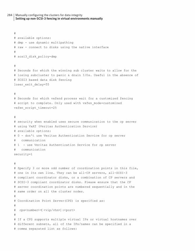
#
# available options:
# dmp - use dynamic multipathing
# raw - connect to disks using the native interface
#
# scsi3_disk_policy=dmp
#
# Seconds for which the winning sub cluster waits to allow for the
# losing subcluster to panic & drain I/Os. Useful in the absence of
# SCSI3 based data disk fencing
loser_exit_delay=55
#
# Seconds for which vxfend process wait for a customized fencing
# script to complete. Only used with vxfen_mode=customized
vxfen_script_timeout=25
#
# security when enabled uses secure communication to the cp server
# using VxAT (Veritas Authentication Service)
# available options:
# 0 - don't use Veritas Authentication Service for cp server
# communication
# 1 - use Veritas Authentication Service for cp server
# communication
security=1
#
# Specify 3 or more odd number of coordination points in this file,
# one in its own line. They can be all-CP servers, all-SCSI-3
# compliant coordinator disks, or a combination of CP servers and
# SCSI-3 compliant coordinator disks. Please ensure that the CP
# server coordination points are numbered sequentially and in the
# same order on all the cluster nodes.
#
# Coordination Point Server(CPS) is specified as:
#
# cps<number>=[<vip/vhn>]:<port>
#
# If a CPS supports multiple virtual IPs or virtual hostnames over
# different subnets, all of the IPs/names can be specified in a
# comma separated list as follows:
Manually configuring the clusters for data integritySetting up non-SCSI-3 fencing in virtual environments manually
284
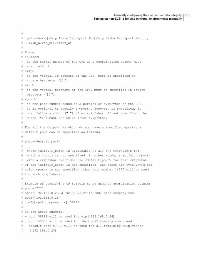
#
# cps<number>=[<vip_1/vhn_1>]:<port_1>,[<vip_2/vhn_2>]:<port_2>,...,
# [<vip_n/vhn_n>]:<port_n>
#
# Where,
# <number>
# is the serial number of the CPS as a coordination point; must
# start with 1.
# <vip>
# is the virtual IP address of the CPS, must be specified in
# square brackets ("[]").
# <vhn>
# is the virtual hostname of the CPS, must be specified in square
# brackets ("[]").
# <port>
# is the port number bound to a particular <vip/vhn> of the CPS.
# It is optional to specify a <port>. However, if specified, it
# must follow a colon (":") after <vip/vhn>. If not specified, the
# colon (":") must not exist after <vip/vhn>.
#
# For all the <vip/vhn>s which do not have a specified <port>, a
# default port can be specified as follows:
#
# port=<default_port>
#
# Where <default_port> is applicable to all the <vip/vhn>s for
# which a <port> is not specified. In other words, specifying <port>
# with a <vip/vhn> overrides the <default_port> for that <vip/vhn>.
# If the <default_port> is not specified, and there are <vip/vhn>s for
# which <port> is not specified, then port number 14250 will be used
# for such <vip/vhn>s.
#
# Example of specifying CP Servers to be used as coordination points:
# port=57777
# cps1=[192.168.0.23],[192.168.0.24]:58888,[cps1.company.com]
# cps2=[192.168.0.25]
# cps3=[cps2.company.com]:59999
#
# In the above example,
# - port 58888 will be used for vip [192.168.0.24]
# - port 59999 will be used for vhn [cps2.company.com], and
# - default port 57777 will be used for all remaining <vip/vhn>s:
# [192.168.0.23]
285Manually configuring the clusters for data integritySetting up non-SCSI-3 fencing in virtual environments manually
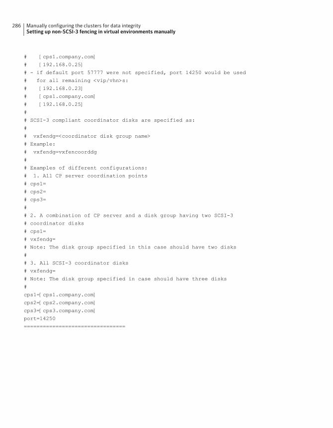
# [cps1.company.com]
# [192.168.0.25]
# - if default port 57777 were not specified, port 14250 would be used
# for all remaining <vip/vhn>s:
# [192.168.0.23]
# [cps1.company.com]
# [192.168.0.25]
#
# SCSI-3 compliant coordinator disks are specified as:
#
# vxfendg=<coordinator disk group name>
# Example:
# vxfendg=vxfencoorddg
#
# Examples of different configurations:
# 1. All CP server coordination points
# cps1=
# cps2=
# cps3=
#
# 2. A combination of CP server and a disk group having two SCSI-3
# coordinator disks
# cps1=
# vxfendg=
# Note: The disk group specified in this case should have two disks
#
# 3. All SCSI-3 coordinator disks
# vxfendg=
# Note: The disk group specified in case should have three disks
#
cps1=[cps1.company.com]
cps2=[cps2.company.com]
cps3=[cps3.company.com]
port=14250
================================
Manually configuring the clusters for data integritySetting up non-SCSI-3 fencing in virtual environments manually
286
Upgrading VCS
■ Chapter 19. Planning to upgrade VCS
■ Chapter 20. Performing a typical VCS upgrade using the installer
■ Chapter 21. Performing a phased upgrade of VCS
■ Chapter 22. Performing an automated VCS upgrade using response files
■ Chapter 23. Performing a rolling upgrade
■ Chapter 24. Upgrading using Live Upgrade
7Section

288
Planning to upgrade VCS
This chapter includes the following topics:
■ About upgrading to VCS 6.0.1
■ VCS supported upgrade paths
■ Upgrading VCS in secure enterprise environments
■ Considerations for upgrading secure VCS 5.x clusters to VCS 6.0.1
■ Considerations for upgrading secure CP servers
■ Considerations for upgrading secure CP clients
■ Setting up trust relationship between CP server and CP clients manually
About upgrading to VCS 6.0.1You can upgrade VCS using one of the following methods:
■ Typical upgrade using Veritas product installer or the installvcs programSee “VCS supported upgrade paths” on page 290.See “Upgrading VCS using the script-based installer” on page 297.
■ Typical upgrade using Veritas Web installerSee “VCS supported upgrade paths” on page 290.See “Upgrading Veritas Cluster Server using the Veritas Web-based installer”on page 299.
■ Phased upgrade to reduce downtimeSee “Performing a phased upgrade” on page 304.
■ Automated upgrade using response filesSee “VCS supported upgrade paths” on page 290.See “Upgrading VCS using response files” on page 323.
19Chapter
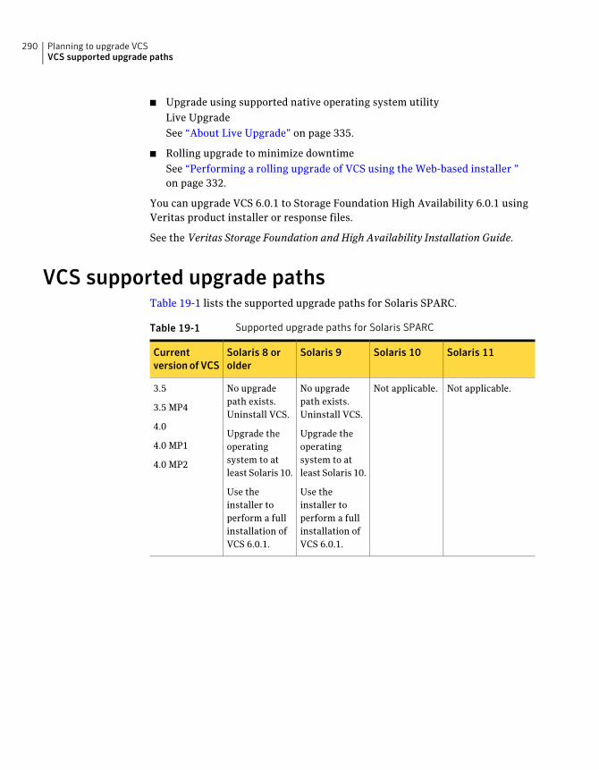
■ Upgrade using supported native operating system utilityLive UpgradeSee “About Live Upgrade” on page 335.
■ Rolling upgrade to minimize downtimeSee “Performing a rolling upgrade of VCS using the Web-based installer ”on page 332.
You can upgrade VCS 6.0.1 to Storage Foundation High Availability 6.0.1 usingVeritas product installer or response files.
See the Veritas Storage Foundation and High Availability Installation Guide.
VCS supported upgrade pathsTable 19-1 lists the supported upgrade paths for Solaris SPARC.
Table 19-1 Supported upgrade paths for Solaris SPARC
Solaris 11Solaris 10Solaris 9Solaris 8 orolder
Currentversionof VCS
Not applicable.Not applicable.No upgradepath exists.Uninstall VCS.
Upgrade theoperatingsystem to atleast Solaris 10.
Use theinstaller toperform a fullinstallation ofVCS 6.0.1.
No upgradepath exists.Uninstall VCS.
Upgrade theoperatingsystem to atleast Solaris 10.
Use theinstaller toperform a fullinstallation ofVCS 6.0.1.
3.5
3.5 MP4
4.0
4.0 MP1
4.0 MP2
Planning to upgrade VCSVCS supported upgrade paths
290
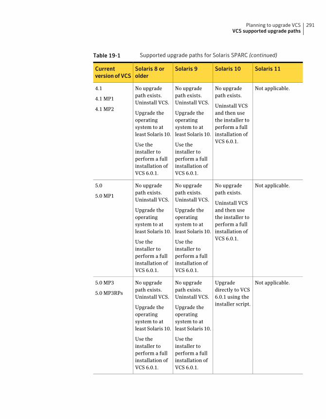
Table 19-1 Supported upgrade paths for Solaris SPARC (continued)
Solaris 11Solaris 10Solaris 9Solaris 8 orolder
Currentversionof VCS
Not applicable.No upgradepath exists.
Uninstall VCSand then usethe installer toperform a fullinstallation ofVCS 6.0.1.
No upgradepath exists.Uninstall VCS.
Upgrade theoperatingsystem to atleast Solaris 10.
Use theinstaller toperform a fullinstallation ofVCS 6.0.1.
No upgradepath exists.Uninstall VCS.
Upgrade theoperatingsystem to atleast Solaris 10.
Use theinstaller toperform a fullinstallation ofVCS 6.0.1.
4.1
4.1 MP1
4.1 MP2
Not applicable.No upgradepath exists.
Uninstall VCSand then usethe installer toperform a fullinstallation ofVCS 6.0.1.
No upgradepath exists.Uninstall VCS.
Upgrade theoperatingsystem to atleast Solaris 10.
Use theinstaller toperform a fullinstallation ofVCS 6.0.1.
No upgradepath exists.Uninstall VCS.
Upgrade theoperatingsystem to atleast Solaris 10.
Use theinstaller toperform a fullinstallation ofVCS 6.0.1.
5.0
5.0 MP1
Not applicable.Upgradedirectly to VCS6.0.1 using theinstaller script.
No upgradepath exists.Uninstall VCS.
Upgrade theoperatingsystem to atleast Solaris 10.
Use theinstaller toperform a fullinstallation ofVCS 6.0.1.
No upgradepath exists.Uninstall VCS.
Upgrade theoperatingsystem to atleast Solaris 10.
Use theinstaller toperform a fullinstallation ofVCS 6.0.1.
5.0 MP3
5.0 MP3RPs
291Planning to upgrade VCSVCS supported upgrade paths
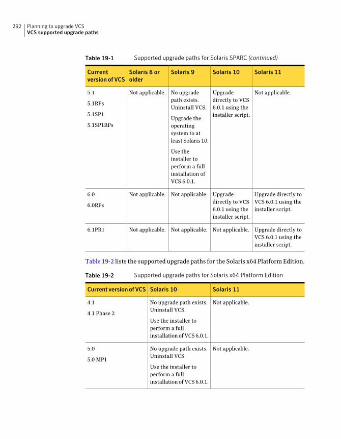
Table 19-1 Supported upgrade paths for Solaris SPARC (continued)
Solaris 11Solaris 10Solaris 9Solaris 8 orolder
Currentversionof VCS
Not applicable.Upgradedirectly to VCS6.0.1 using theinstaller script.
No upgradepath exists.Uninstall VCS.
Upgrade theoperatingsystem to atleast Solaris 10.
Use theinstaller toperform a fullinstallation ofVCS 6.0.1.
Not applicable.5.1
5.1RPs
5.1SP1
5.1SP1RPs
Upgrade directly toVCS 6.0.1 using theinstaller script.
Upgradedirectly to VCS6.0.1 using theinstaller script.
Not applicable.Not applicable.6.0
6.0RPs
Upgrade directly toVCS 6.0.1 using theinstaller script.
Not applicable.Not applicable.Not applicable.6.1PR1
Table 19-2 lists the supported upgrade paths for the Solaris x64 Platform Edition.
Table 19-2 Supported upgrade paths for Solaris x64 Platform Edition
Solaris 11Solaris 10Current versionofVCS
Not applicable.No upgrade path exists.Uninstall VCS.
Use the installer toperform a fullinstallation of VCS 6.0.1.
4.1
4.1 Phase 2
Not applicable.No upgrade path exists.Uninstall VCS.
Use the installer toperform a fullinstallation of VCS 6.0.1.
5.0
5.0 MP1
Planning to upgrade VCSVCS supported upgrade paths
292
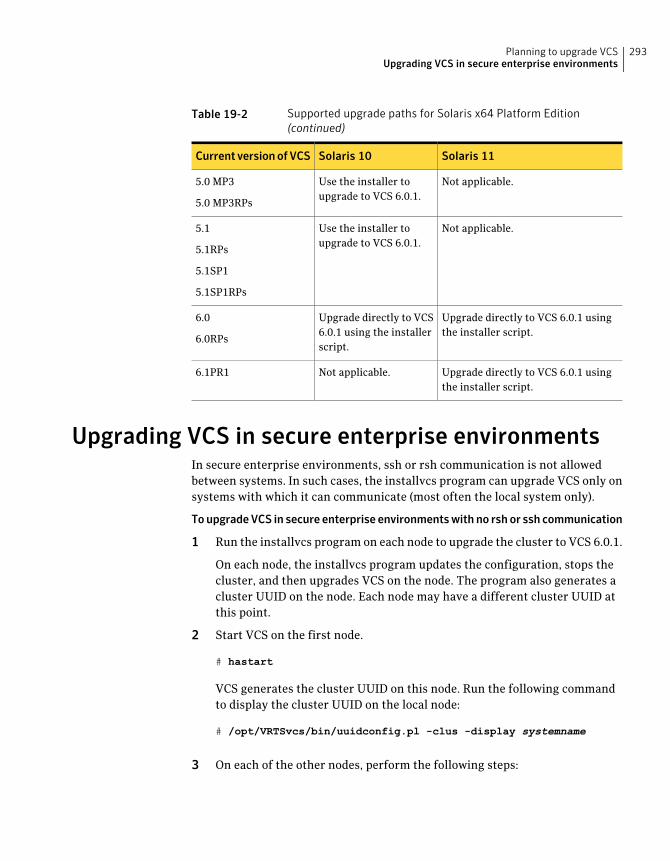
Table 19-2 Supported upgrade paths for Solaris x64 Platform Edition(continued)
Solaris 11Solaris 10Current versionofVCS
Not applicable.Use the installer toupgrade to VCS 6.0.1.
5.0 MP3
5.0 MP3RPs
Not applicable.Use the installer toupgrade to VCS 6.0.1.
5.1
5.1RPs
5.1SP1
5.1SP1RPs
Upgrade directly to VCS 6.0.1 usingthe installer script.
Upgrade directly to VCS6.0.1 using the installerscript.
6.0
6.0RPs
Upgrade directly to VCS 6.0.1 usingthe installer script.
Not applicable.6.1PR1
Upgrading VCS in secure enterprise environmentsIn secure enterprise environments, ssh or rsh communication is not allowedbetween systems. In such cases, the installvcs program can upgrade VCS only onsystems with which it can communicate (most often the local system only).
ToupgradeVCS in secure enterprise environmentswithno rshor ssh communication
1 Run the installvcs program on each node to upgrade the cluster to VCS 6.0.1.
On each node, the installvcs program updates the configuration, stops thecluster, and then upgrades VCS on the node. The program also generates acluster UUID on the node. Each node may have a different cluster UUID atthis point.
2 Start VCS on the first node.
# hastart
VCS generates the cluster UUID on this node. Run the following commandto display the cluster UUID on the local node:
# /opt/VRTSvcs/bin/uuidconfig.pl -clus -display systemname
3 On each of the other nodes, perform the following steps:
293Planning to upgrade VCSUpgrading VCS in secure enterprise environments
■ Set the value of the VCS_HOST environment variable to the name of thefirst node.
■ Display the value of the CID attribute that stores the cluster UUID value:
# haclus -value CID
■ Copy the output of the CID attribute to the file /etc/vx/.uuids/clusuuid.
■ Update the VCS_HOST environment variable to remove the set value.
■ Start VCS.The node must successfully join the already running nodes in the cluster.See “Verifying LLT, GAB, and cluster operation” on page 374.
Considerations for upgrading secure VCS 5.x clustersto VCS 6.0.1
When you upgrade a secure VCS 5.x cluster to VCS 6.0.1, the upgrade does notmigrate the old broker configuration to the new broker because of the change inarchitecture. Both the old broker (/opt/VRTSat/bin/vxatd) and new broker(/opt/VRTSvcs/bin/vcsauth/vcsauthserver/bin/vcsauthserver) continue torun. In such a scenario, you must consider the following:
■ The HA commands that you run in VCS 6.0.1 are processed by the new brokerby default. To ensure that the HA commands are processed by the old broker,set the VCS_REMOTE_BROKER environment variable as follows:
# export VCS_REMOTE_BROKER=localhost IP,2821
See “About enabling LDAP authentication for clusters that run in secure mode”on page 357.
■ VCS 6.0.1 does not prompt non-root users who run HA commands forpasswords. In 5.x, non-root users required a password to run HA commands.If you want non-root users to enter passwords before they run HA commands,set the VCS_DOMAINTYPE environment variable to unixpwd.
■ Trust relationships are not migrated during the upgrade. If you had configuredsecure GCO or secure steward, ensure that trust relationships are recreatedbetween the clusters and the steward.See “Setting up trust relationships for your VCS cluster” on page 137.
■ For Zones, the HA commands run within the container and use credentialsthat were deployed by the old broker. However, you can migrate to the newercredentials from the new broker by running hazonesetup again.
Planning to upgrade VCSConsiderations for upgrading secure VCS 5.x clusters to VCS 6.0.1
294
When the old broker is not used anymore, you can delete the old VRTSat package.
Considerations for upgrading secure CP serversWhen you upgrade the CP Server, trust relationships are not migrated.
If you upgrade the CP clients after you upgrade the CP server, the installerrecreates the trust relationships that were established by the client. You need notestablish the trust relationships manually. However, the CP server and CP clientscannot communicate with each other till trust relationships are established.
If you do not upgrade the CP clients after you upgrade the CP server, you mustrecreate the trust relationships between the CP server and CP clients.
Considerations for upgrading secure CP clientsPasswordless communication from CP clients to CP server must exist for theinstaller to reconfigure fencing and to recreate the trust relationships after theupgrade. If passwordless communication does not exist, you must reconfigurefencing manually.
See “Setting up disk-based I/O fencing manually” on page 263.
See “Setting up server-based I/O fencing manually” on page 268.
Setting up trust relationship between CP server andCP clients manually
For each client cluster, run the following command on the CP server:
EAT_DATA_DIR=/var/VRTSvcs/vcsauth/data/CPSERVER \
/opt/VRTSvcs/bin/vcsat setuptrust -b client_ip_addres:14149 -s high
On each client node, run the following command:
EAT_DATA_DIR=/var/VRTSvcs/vcsauth/data/CPSADM \
/opt/VRTSvcs/bin/vcsat setuptrust -b cpserver_ip_address:14149 -s high
295Planning to upgrade VCSConsiderations for upgrading secure CP servers

Planning to upgrade VCSSetting up trust relationship between CP server and CP clients manually
296
Performing a typical VCSupgrade using the installer
This chapter includes the following topics:
■ Before upgrading using the script-based or Web-based installer
■ Upgrading VCS using the script-based installer
■ Upgrading Veritas Cluster Server using the Veritas Web-based installer
Before upgrading using the script-based orWeb-based installer
Before you upgrade VCS, perform the following steps. You first need to removedeprecated resource types and modify changed values.
To prepare to upgrade to VCS 6.0.1
◆ Make sure that all non-global zones are booted and in the running state beforeyou install or upgrade the VCS packages in the global zone. If the non-globalzones are not mounted and running at the time of upgrade, you must upgradeeach package in each non-global zone manually.
Upgrading VCS using the script-based installerYou can use the product installer to upgrade VCS.
20Chapter
To upgrade VCS using the product installer
1 Log in as superuser and mount the product disc.
2 Start the installer.
# ./installer
The installer starts the product installation program with a copyright message.It then specifies where it creates the logs. Note the log's directory and name.
3 From the opening Selection Menu, choose: G for "Upgrade a Product."
4 Choose 1 for Full Upgrade.
5 Enter the names of the nodes that you want to upgrade. Use spaces to separatenode names. Press the Enter key to proceed.
The installer runs some verification checks on the nodes.
6 When the verification checks are complete, the installer asks if you agreewith the terms of the End User License Agreement. Press y to agree andcontinue.
The installer lists the packages to upgrade.
7 The installer asks if you want to stop VCS processes. Press the Enter key tocontinue.
The installer stops VCS processes, uninstalls packages, installs or upgradespackages, and configures VCS.
The installer lists the nodes that Symantec recommends you restart.
8 The installer asks if you would like to send the information about thisinstallation to Symantec to help improve installation in the future. Enteryour response.
The installer displays the location of log files, summary file, and responsefile.
9 If you want to upgrade CP server systems that use VCS or SFHA to VCS 6.0.1,make sure that you first upgrade all application clusters to version VCS 6.0.1.Then, upgrade VCS or SFHA on the CP server systems.
For instructions to upgrade VCS or SFHA, see the Veritas Cluster ServerInstallationGuide or the StorageFoundationandHighAvailability InstallationGuide.
If you are upgrading from 4.x, you may need to create new VCS accounts if youused native OS accounts.
See “Creating new VCS accounts if you used native operating system accounts”on page 483.
Performing a typical VCS upgrade using the installerUpgrading VCS using the script-based installer
298
Upgrading Veritas Cluster Server using the VeritasWeb-based installer
This section describes upgrading VCS with the Veritas Web-based installer. Theinstaller detects and upgrades the product that is currently installed on thespecified system or systems.
To upgrade VCS
1 Perform the required steps to save any data that you wish to preserve. Forexample, make configuration file backups.
2 If you are upgrading a high availability (HA) product, take all service groupsoffline. List all service groups:
# /opt/VRTSvcs/bin/hagrp -list
For each service group listed, take it offline:
# /opt/VRTSvcs/bin/hagrp -offline service_group -any
3 Start the Web-based installer.
See “Starting the Veritas Web-based installer” on page 176.
4 On the Select a task and a product page, select Upgrade a Product from theTask drop-down menu.
The installer detects the product that is installed on the specified system.Click Next.
5 Indicate the systems on which to upgrade. Enter one or more system names,separated by spaces. Click Next.
6 On the License agreement page, select whether you accept the terms of theEnd User License Agreement (EULA). To continue, select YesIagree and clickNext.
7 Click Next to complete the upgrade.
After the upgrade completes, the installer displays the location of the log andsummary files. If required, view the files to confirm the installation status.
8 If you are prompted to reboot the systems, enter the following rebootcommand:
# /usr/sbin/shutdown -r now
299Performing a typical VCS upgrade using the installerUpgrading Veritas Cluster Server using the Veritas Web-based installer
9 After the upgrade, if the product is not configured, the Web-based installerasks: "Do you want to configure this product?" If the product is alreadyconfigured, it will not ask any questions.
10 Click Finish. The installer prompts you for another task.
11 If you want to upgrade VCS or SFHA 5.1 on the CP server systems to versionVCS 6.0.1, make sure that you upgraded all application clusters to versionVCS 6.0.1. Then, upgrade VCS or SFHA on the CP server systems. Forinstructions to upgrade VCS or SFHA, see the VCS or SFHA Installation Guide.
If you are upgrading from 4.x, you may need to create new VCS accounts if youused native operating system accounts.
See “Creating new VCS accounts if you used native operating system accounts”on page 483.
Performing a typical VCS upgrade using the installerUpgrading Veritas Cluster Server using the Veritas Web-based installer
300
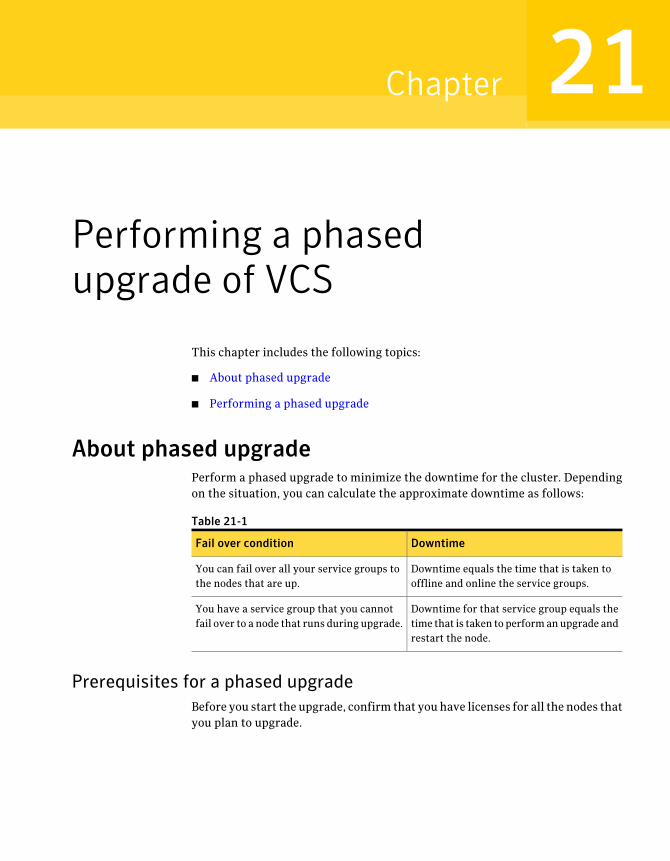
Performing a phasedupgrade of VCS
This chapter includes the following topics:
■ About phased upgrade
■ Performing a phased upgrade
About phased upgradePerform a phased upgrade to minimize the downtime for the cluster. Dependingon the situation, you can calculate the approximate downtime as follows:
Table 21-1
DowntimeFail over condition
Downtime equals the time that is taken tooffline and online the service groups.
You can fail over all your service groups tothe nodes that are up.
Downtime for that service group equals thetime that is taken to perform an upgrade andrestart the node.
You have a service group that you cannotfail over to a node that runs during upgrade.
Prerequisites for a phased upgradeBefore you start the upgrade, confirm that you have licenses for all the nodes thatyou plan to upgrade.
21Chapter
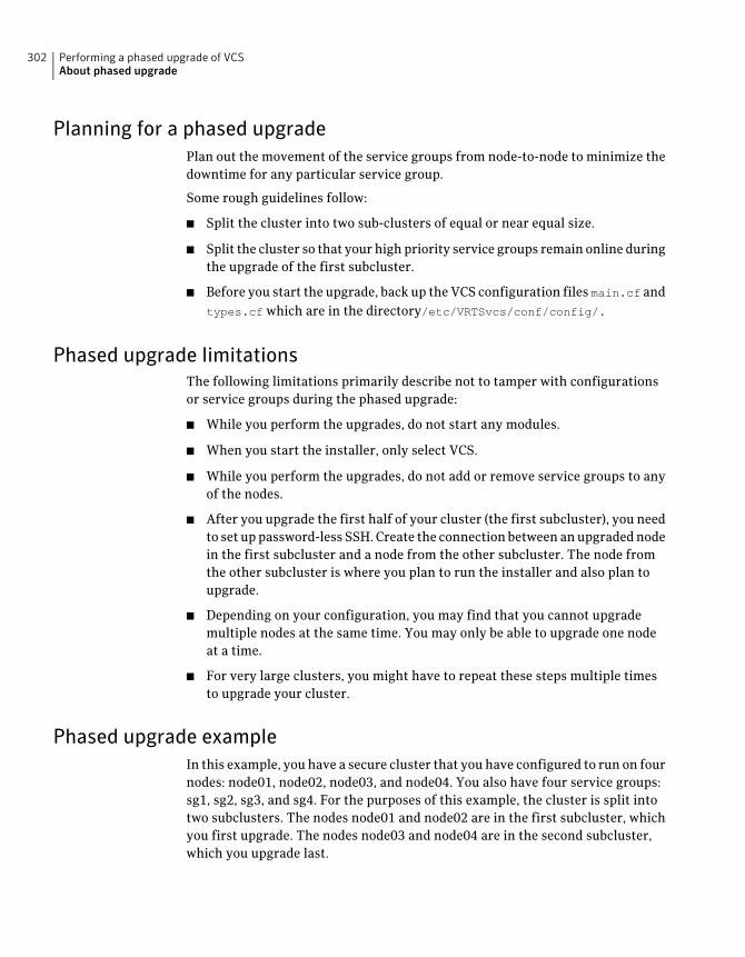
Planning for a phased upgradePlan out the movement of the service groups from node-to-node to minimize thedowntime for any particular service group.
Some rough guidelines follow:
■ Split the cluster into two sub-clusters of equal or near equal size.
■ Split the cluster so that your high priority service groups remain online duringthe upgrade of the first subcluster.
■ Before you start the upgrade, back up the VCS configuration files main.cf andtypes.cf which are in the directory/etc/VRTSvcs/conf/config/.
Phased upgrade limitationsThe following limitations primarily describe not to tamper with configurationsor service groups during the phased upgrade:
■ While you perform the upgrades, do not start any modules.
■ When you start the installer, only select VCS.
■ While you perform the upgrades, do not add or remove service groups to anyof the nodes.
■ After you upgrade the first half of your cluster (the first subcluster), you needto set up password-less SSH. Create the connection between an upgraded nodein the first subcluster and a node from the other subcluster. The node fromthe other subcluster is where you plan to run the installer and also plan toupgrade.
■ Depending on your configuration, you may find that you cannot upgrademultiple nodes at the same time. You may only be able to upgrade one nodeat a time.
■ For very large clusters, you might have to repeat these steps multiple timesto upgrade your cluster.
Phased upgrade exampleIn this example, you have a secure cluster that you have configured to run on fournodes: node01, node02, node03, and node04. You also have four service groups:sg1, sg2, sg3, and sg4. For the purposes of this example, the cluster is split intotwo subclusters. The nodes node01 and node02 are in the first subcluster, whichyou first upgrade. The nodes node03 and node04 are in the second subcluster,which you upgrade last.
Performing a phased upgrade of VCSAbout phased upgrade
302
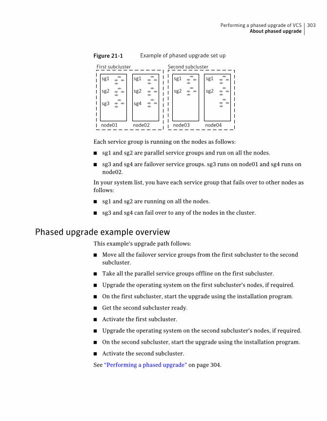
Figure 21-1 Example of phased upgrade set up
node01 node04node03node02
First subcluster Second subcluster
sg1
sg2
sg3
sg1
sg2
sg4
sg1
sg2
sg1
sg2
Each service group is running on the nodes as follows:
■ sg1 and sg2 are parallel service groups and run on all the nodes.
■ sg3 and sg4 are failover service groups. sg3 runs on node01 and sg4 runs onnode02.
In your system list, you have each service group that fails over to other nodes asfollows:
■ sg1 and sg2 are running on all the nodes.
■ sg3 and sg4 can fail over to any of the nodes in the cluster.
Phased upgrade example overviewThis example's upgrade path follows:
■ Move all the failover service groups from the first subcluster to the secondsubcluster.
■ Take all the parallel service groups offline on the first subcluster.
■ Upgrade the operating system on the first subcluster's nodes, if required.
■ On the first subcluster, start the upgrade using the installation program.
■ Get the second subcluster ready.
■ Activate the first subcluster.
■ Upgrade the operating system on the second subcluster's nodes, if required.
■ On the second subcluster, start the upgrade using the installation program.
■ Activate the second subcluster.
See “Performing a phased upgrade” on page 304.
303Performing a phased upgrade of VCSAbout phased upgrade
Performing a phased upgradeThis section explains how to perform a phased upgrade of VCS on four nodes withfour service groups. Note that in this scenario, VCS and the service groups cannotstay online on the second subcluster during the upgrade of the second subcluster.Do not add, remove, or change resources or service groups on any nodes duringthe upgrade. These changes are likely to get lost after the upgrade.
An example of a phased upgrade follows. It illustrates the steps to perform aphased upgrade. The example makes use of a secure VCS cluster.
You can perform a phased upgrade from VCS 5.1 or other supported previousversions to VCS 6.0.1.
See “About phased upgrade” on page 301.
See “Phased upgrade example” on page 302.
Moving the service groups to the second subclusterPerform the following steps to establish the service group's status and to switchthe service groups.
Performing a phased upgrade of VCSPerforming a phased upgrade
304
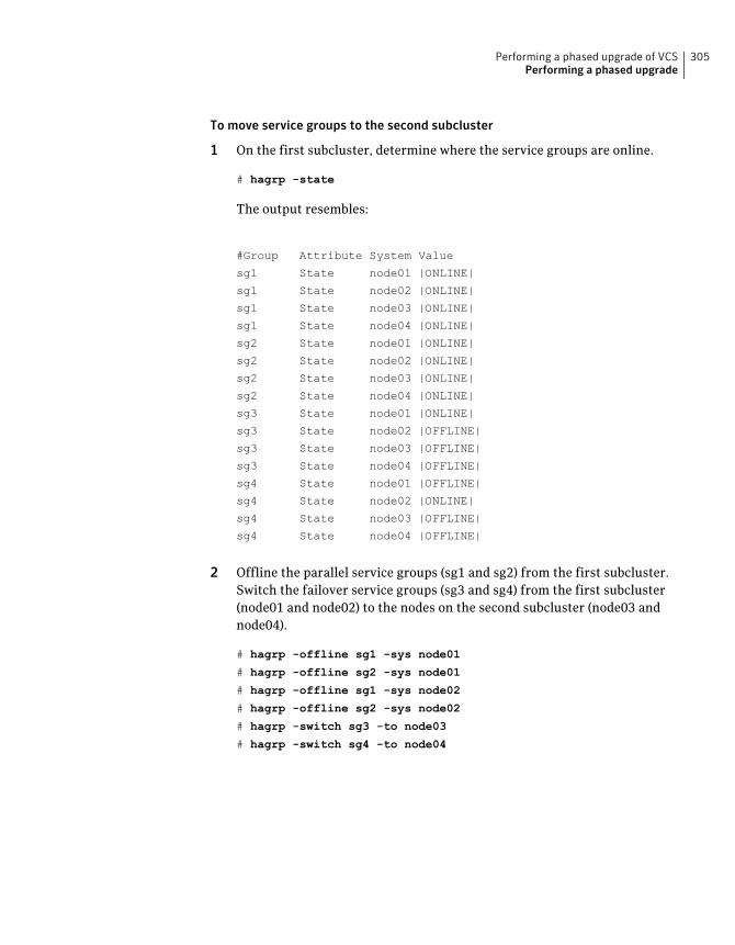
To move service groups to the second subcluster
1 On the first subcluster, determine where the service groups are online.
# hagrp -state
The output resembles:
#Group Attribute System Value
sg1 State node01 |ONLINE|
sg1 State node02 |ONLINE|
sg1 State node03 |ONLINE|
sg1 State node04 |ONLINE|
sg2 State node01 |ONLINE|
sg2 State node02 |ONLINE|
sg2 State node03 |ONLINE|
sg2 State node04 |ONLINE|
sg3 State node01 |ONLINE|
sg3 State node02 |OFFLINE|
sg3 State node03 |OFFLINE|
sg3 State node04 |OFFLINE|
sg4 State node01 |OFFLINE|
sg4 State node02 |ONLINE|
sg4 State node03 |OFFLINE|
sg4 State node04 |OFFLINE|
2 Offline the parallel service groups (sg1 and sg2) from the first subcluster.Switch the failover service groups (sg3 and sg4) from the first subcluster(node01 and node02) to the nodes on the second subcluster (node03 andnode04).
# hagrp -offline sg1 -sys node01
# hagrp -offline sg2 -sys node01
# hagrp -offline sg1 -sys node02
# hagrp -offline sg2 -sys node02
# hagrp -switch sg3 -to node03
# hagrp -switch sg4 -to node04
305Performing a phased upgrade of VCSPerforming a phased upgrade
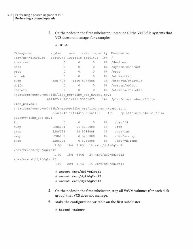
3 On the nodes in the first subcluster, unmount all the VxFS file systems thatVCS does not manage, for example:
# df -k
Filesystem kbytes used avail capacity Mounted on
/dev/dsk/c1t0d0s0 66440242 10114415 55661425 16% /
/devices 0 0 0 0% /devices
ctfs 0 0 0 0% /system/contract
proc 0 0 0 0% /proc
mnttab 0 0 0 0% /etc/mnttab
swap 5287408 1400 5286008 1% /etc/svc/volatile
objfs 0 0 0 0% /system/object
sharefs 0 0 0 0% /etc/dfs/sharetab
/platform/sun4u-us3/lib/libc_psr/libc_psr_hwcap1.so.1
66440242 10114415 55661425 16% /platform/sun4u-us3/lib/
libc_psr.so.1
/platform/sun4u-us3/lib/sparcv9/libc_psr/libc_psr_hwcap1.so.1
66440242 10114415 55661425 16% /platform/sun4u-us3/lib/
sparcv9/libc_psr.so.1
fd 0 0 0 0% /dev/fd
swap 5286064 56 5286008 1% /tmp
swap 5286056 48 5286008 1% /var/run
swap 5286008 0 5286008 0% /dev/vx/dmp
swap 5286008 0 5286008 0% /dev/vx/rdmp
3.0G 18M 2.8G 1% /mnt/dg2/dg2vol1
/dev/vx/dsk/dg2/dg2vol2
1.0G 18M 944M 2% /mnt/dg2/dg2vol2
/dev/vx/dsk/dg2/dg2vol3
10G 20M 9.4G 1% /mnt/dg2/dg2vol3
# umount /mnt/dg2/dg2vol1
# umount /mnt/dg2/dg2vol2
# umount /mnt/dg2/dg2vol3
4 On the nodes in the first subcluster, stop all VxVM volumes (for each diskgroup) that VCS does not manage.
5 Make the configuration writable on the first subcluster.
# haconf -makerw
Performing a phased upgrade of VCSPerforming a phased upgrade
306
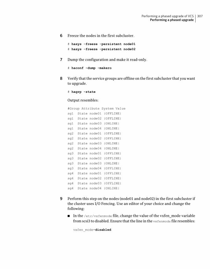
6 Freeze the nodes in the first subcluster.
# hasys -freeze -persistent node01
# hasys -freeze -persistent node02
7 Dump the configuration and make it read-only.
# haconf -dump -makero
8 Verify that the service groups are offline on the first subcluster that you wantto upgrade.
# hagrp -state
Output resembles:
#Group Attribute System Value
sg1 State node01 |OFFLINE|
sg1 State node02 |OFFLINE|
sg1 State node03 |ONLINE|
sg1 State node04 |ONLINE|
sg2 State node01 |OFFLINE|
sg2 State node02 |OFFLINE|
sg2 State node03 |ONLINE|
sg2 State node04 |ONLINE|
sg3 State node01 |OFFLINE|
sg3 State node02 |OFFLINE|
sg3 State node03 |ONLINE|
sg3 State node04 |OFFLINE|
sg4 State node01 |OFFLINE|
sg4 State node02 |OFFLINE|
sg4 State node03 |OFFLINE|
sg4 State node04 |ONLINE|
9 Perform this step on the nodes (node01 and node02) in the first subcluster ifthe cluster uses I/O Fencing. Use an editor of your choice and change thefollowing:
■ In the /etc/vxfenmode file, change the value of the vxfen_mode variablefrom scsi3 to disabled. Ensure that the line in the vxfenmode file resembles:
vxfen_mode=disabled
307Performing a phased upgrade of VCSPerforming a phased upgrade
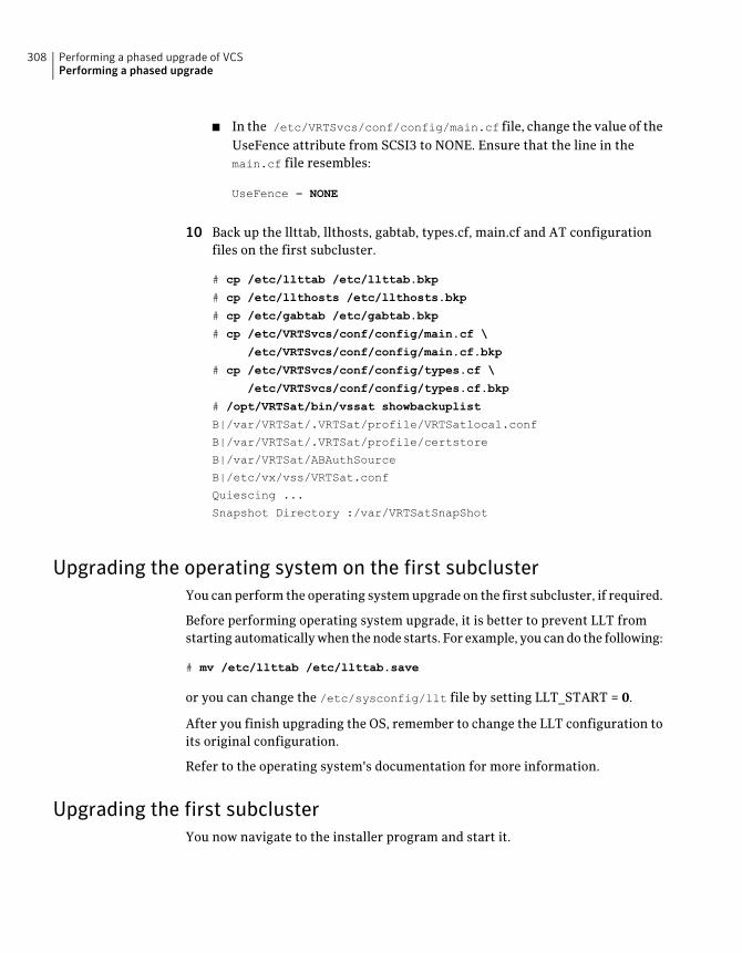
■ In the /etc/VRTSvcs/conf/config/main.cf file, change the value of theUseFence attribute from SCSI3 to NONE. Ensure that the line in themain.cf file resembles:
UseFence = NONE
10 Back up the llttab, llthosts, gabtab, types.cf, main.cf and AT configurationfiles on the first subcluster.
# cp /etc/llttab /etc/llttab.bkp
# cp /etc/llthosts /etc/llthosts.bkp
# cp /etc/gabtab /etc/gabtab.bkp
# cp /etc/VRTSvcs/conf/config/main.cf \
/etc/VRTSvcs/conf/config/main.cf.bkp
# cp /etc/VRTSvcs/conf/config/types.cf \
/etc/VRTSvcs/conf/config/types.cf.bkp
# /opt/VRTSat/bin/vssat showbackuplist
B|/var/VRTSat/.VRTSat/profile/VRTSatlocal.conf
B|/var/VRTSat/.VRTSat/profile/certstore
B|/var/VRTSat/ABAuthSource
B|/etc/vx/vss/VRTSat.conf
Quiescing ...
Snapshot Directory :/var/VRTSatSnapShot
Upgrading the operating system on the first subclusterYou can perform the operating system upgrade on the first subcluster, if required.
Before performing operating system upgrade, it is better to prevent LLT fromstarting automatically when the node starts. For example, you can do the following:
# mv /etc/llttab /etc/llttab.save
or you can change the /etc/sysconfig/llt file by setting LLT_START = 0.
After you finish upgrading the OS, remember to change the LLT configuration toits original configuration.
Refer to the operating system's documentation for more information.
Upgrading the first subclusterYou now navigate to the installer program and start it.
Performing a phased upgrade of VCSPerforming a phased upgrade
308
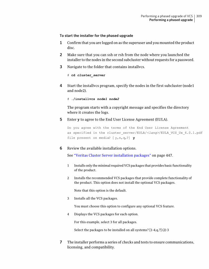
To start the installer for the phased upgrade
1 Confirm that you are logged on as the superuser and you mounted the productdisc.
2 Make sure that you can ssh or rsh from the node where you launched theinstaller to the nodes in the second subcluster without requests for a password.
3 Navigate to the folder that contains installvcs.
# cd cluster_server
4 Start the installvcs program, specify the nodes in the first subcluster (node1and node2).
# ./installvcs node1 node2
The program starts with a copyright message and specifies the directorywhere it creates the logs.
5 Enter y to agree to the End User License Agreement (EULA).
Do you agree with the terms of the End User License Agreement
as specified in the cluster_server/EULA/<lang>/EULA_VCS_Ux_6.0.1.pdf
file present on media? [y,n,q,?] y
6 Review the available installation options.
See “Veritas Cluster Server installation packages” on page 447.
Installs only the minimal required VCS packages that provides basic functionalityof the product.
1
Installs the recommended VCS packages that provide complete functionality ofthe product. This option does not install the optional VCS packages.
2
Note that this option is the default.
Installs all the VCS packages.3
You must choose this option to configure any optional VCS feature.
Displays the VCS packages for each option.4
For this example, select 3 for all packages.
Select the packages to be installed on all systems? [1-4,q,?] (2) 3
7 The installer performs a series of checks and tests to ensure communications,licensing, and compatibility.
309Performing a phased upgrade of VCSPerforming a phased upgrade
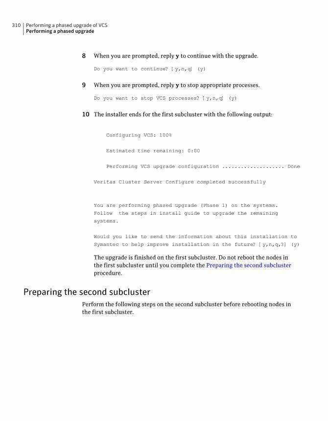
8 When you are prompted, reply y to continue with the upgrade.
Do you want to continue? [y,n,q] (y)
9 When you are prompted, reply y to stop appropriate processes.
Do you want to stop VCS processes? [y,n,q] (y)
10 The installer ends for the first subcluster with the following output:
Configuring VCS: 100%
Estimated time remaining: 0:00 1 of 1
Performing VCS upgrade configuration .................... Done
Veritas Cluster Server Configure completed successfully
You are performing phased upgrade (Phase 1) on the systems.
Follow the steps in install guide to upgrade the remaining
systems.
Would you like to send the information about this installation to
Symantec to help improve installation in the future? [y,n,q,?] (y)
The upgrade is finished on the first subcluster. Do not reboot the nodes inthe first subcluster until you complete the Preparing the second subclusterprocedure.
Preparing the second subclusterPerform the following steps on the second subcluster before rebooting nodes inthe first subcluster.
Performing a phased upgrade of VCSPerforming a phased upgrade
310
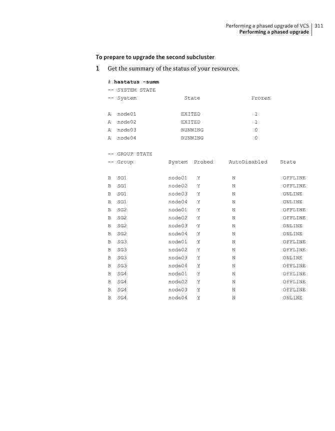
To prepare to upgrade the second subcluster
1 Get the summary of the status of your resources.
# hastatus -summ
-- SYSTEM STATE
-- System State Frozen
A node01 EXITED 1
A node02 EXITED 1
A node03 RUNNING 0
A node04 RUNNING 0
-- GROUP STATE
-- Group System Probed AutoDisabled State
B SG1 node01 Y N OFFLINE
B SG1 node02 Y N OFFLINE
B SG1 node03 Y N ONLINE
B SG1 node04 Y N ONLINE
B SG2 node01 Y N OFFLINE
B SG2 node02 Y N OFFLINE
B SG2 node03 Y N ONLINE
B SG2 node04 Y N ONLINE
B SG3 node01 Y N OFFLINE
B SG3 node02 Y N OFFLINE
B SG3 node03 Y N ONLINE
B SG3 node04 Y N OFFLINE
B SG4 node01 Y N OFFLINE
B SG4 node02 Y N OFFLINE
B SG4 node03 Y N OFFLINE
B SG4 node04 Y N ONLINE
311Performing a phased upgrade of VCSPerforming a phased upgrade
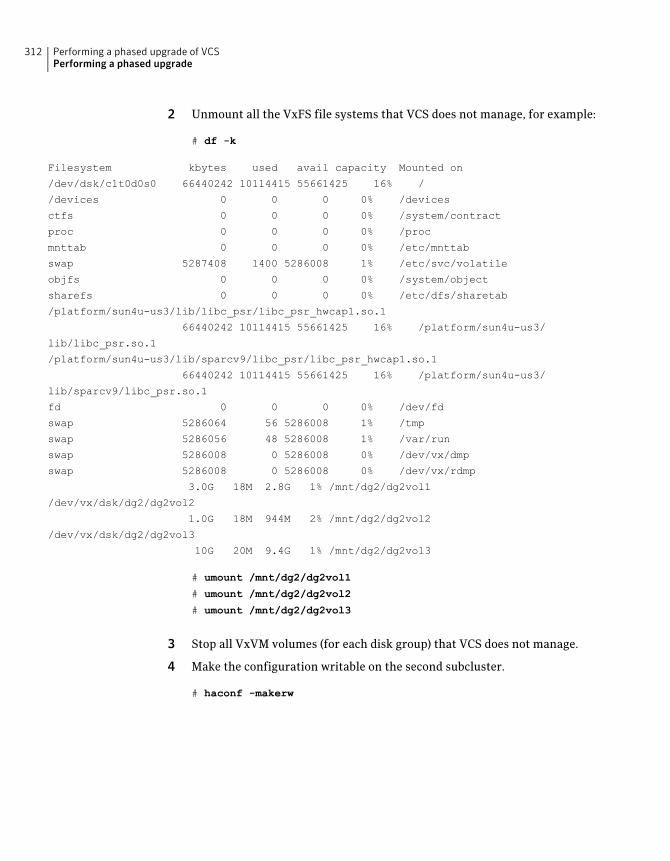
2 Unmount all the VxFS file systems that VCS does not manage, for example:
# df -k
Filesystem kbytes used avail capacity Mounted on
/dev/dsk/c1t0d0s0 66440242 10114415 55661425 16% /
/devices 0 0 0 0% /devices
ctfs 0 0 0 0% /system/contract
proc 0 0 0 0% /proc
mnttab 0 0 0 0% /etc/mnttab
swap 5287408 1400 5286008 1% /etc/svc/volatile
objfs 0 0 0 0% /system/object
sharefs 0 0 0 0% /etc/dfs/sharetab
/platform/sun4u-us3/lib/libc_psr/libc_psr_hwcap1.so.1
66440242 10114415 55661425 16% /platform/sun4u-us3/
lib/libc_psr.so.1
/platform/sun4u-us3/lib/sparcv9/libc_psr/libc_psr_hwcap1.so.1
66440242 10114415 55661425 16% /platform/sun4u-us3/
lib/sparcv9/libc_psr.so.1
fd 0 0 0 0% /dev/fd
swap 5286064 56 5286008 1% /tmp
swap 5286056 48 5286008 1% /var/run
swap 5286008 0 5286008 0% /dev/vx/dmp
swap 5286008 0 5286008 0% /dev/vx/rdmp
3.0G 18M 2.8G 1% /mnt/dg2/dg2vol1
/dev/vx/dsk/dg2/dg2vol2
1.0G 18M 944M 2% /mnt/dg2/dg2vol2
/dev/vx/dsk/dg2/dg2vol3
10G 20M 9.4G 1% /mnt/dg2/dg2vol3
# umount /mnt/dg2/dg2vol1
# umount /mnt/dg2/dg2vol2
# umount /mnt/dg2/dg2vol3
3 Stop all VxVM volumes (for each disk group) that VCS does not manage.
4 Make the configuration writable on the second subcluster.
# haconf -makerw
Performing a phased upgrade of VCSPerforming a phased upgrade
312
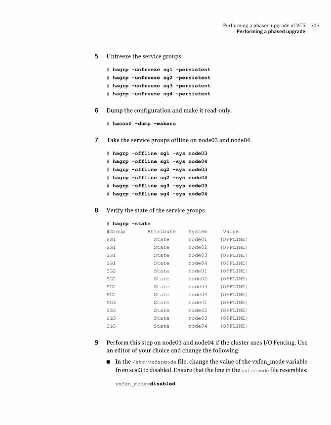
5 Unfreeze the service groups.
# hagrp -unfreeze sg1 -persistent
# hagrp -unfreeze sg2 -persistent
# hagrp -unfreeze sg3 -persistent
# hagrp -unfreeze sg4 -persistent
6 Dump the configuration and make it read-only.
# haconf -dump -makero
7 Take the service groups offline on node03 and node04.
# hagrp -offline sg1 -sys node03
# hagrp -offline sg1 -sys node04
# hagrp -offline sg2 -sys node03
# hagrp -offline sg2 -sys node04
# hagrp -offline sg3 -sys node03
# hagrp -offline sg4 -sys node04
8 Verify the state of the service groups.
# hagrp -state
#Group Attribute System Value
SG1 State node01 |OFFLINE|
SG1 State node02 |OFFLINE|
SG1 State node03 |OFFLINE|
SG1 State node04 |OFFLINE|
SG2 State node01 |OFFLINE|
SG2 State node02 |OFFLINE|
SG2 State node03 |OFFLINE|
SG2 State node04 |OFFLINE|
SG3 State node01 |OFFLINE|
SG3 State node02 |OFFLINE|
SG3 State node03 |OFFLINE|
SG3 State node04 |OFFLINE|
9 Perform this step on node03 and node04 if the cluster uses I/O Fencing. Usean editor of your choice and change the following:
■ In the /etc/vxfenmode file, change the value of the vxfen_mode variablefrom scsi3 to disabled. Ensure that the line in the vxfenmode file resembles:
vxfen_mode=disabled
313Performing a phased upgrade of VCSPerforming a phased upgrade
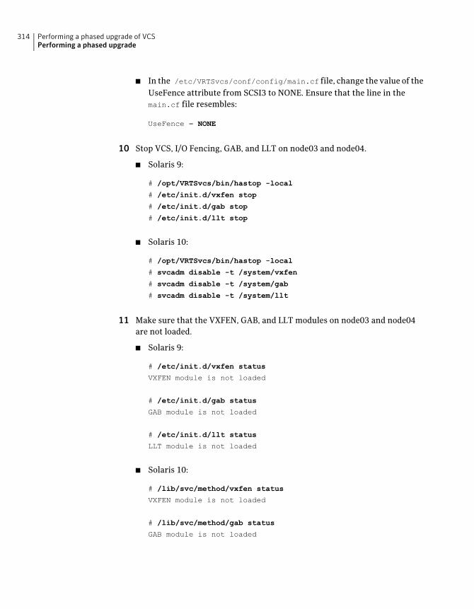
■ In the /etc/VRTSvcs/conf/config/main.cf file, change the value of theUseFence attribute from SCSI3 to NONE. Ensure that the line in themain.cf file resembles:
UseFence = NONE
10 Stop VCS, I/O Fencing, GAB, and LLT on node03 and node04.
■ Solaris 9:
# /opt/VRTSvcs/bin/hastop -local
# /etc/init.d/vxfen stop
# /etc/init.d/gab stop
# /etc/init.d/llt stop
■ Solaris 10:
# /opt/VRTSvcs/bin/hastop -local
# svcadm disable -t /system/vxfen
# svcadm disable -t /system/gab
# svcadm disable -t /system/llt
11 Make sure that the VXFEN, GAB, and LLT modules on node03 and node04are not loaded.
■ Solaris 9:
# /etc/init.d/vxfen status
VXFEN module is not loaded
# /etc/init.d/gab status
GAB module is not loaded
# /etc/init.d/llt status
LLT module is not loaded
■ Solaris 10:
# /lib/svc/method/vxfen status
VXFEN module is not loaded
# /lib/svc/method/gab status
GAB module is not loaded
Performing a phased upgrade of VCSPerforming a phased upgrade
314
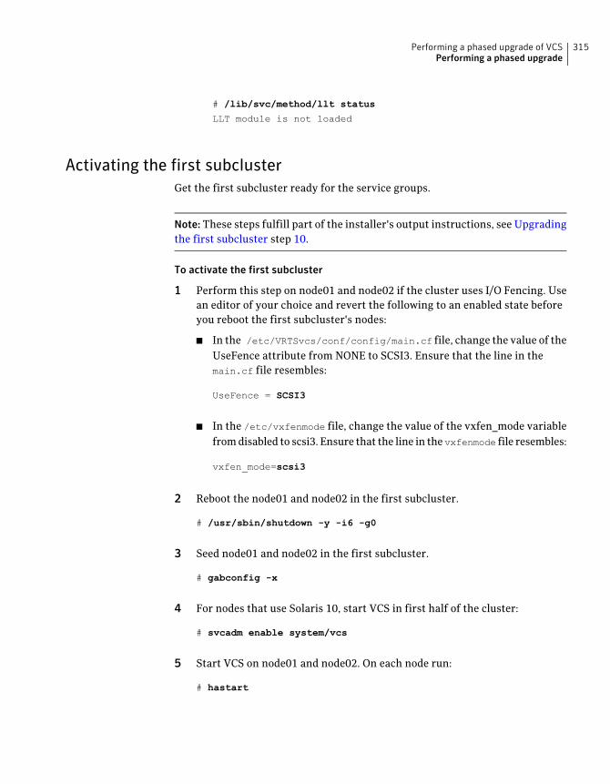
# /lib/svc/method/llt status
LLT module is not loaded
Activating the first subclusterGet the first subcluster ready for the service groups.
Note: These steps fulfill part of the installer's output instructions, see Upgradingthe first subcluster step 10.
To activate the first subcluster
1 Perform this step on node01 and node02 if the cluster uses I/O Fencing. Usean editor of your choice and revert the following to an enabled state beforeyou reboot the first subcluster's nodes:
■ In the /etc/VRTSvcs/conf/config/main.cf file, change the value of theUseFence attribute from NONE to SCSI3. Ensure that the line in themain.cf file resembles:
UseFence = SCSI3
■ In the /etc/vxfenmode file, change the value of the vxfen_mode variablefrom disabled to scsi3. Ensure that the line in the vxfenmode file resembles:
vxfen_mode=scsi3
2 Reboot the node01 and node02 in the first subcluster.
# /usr/sbin/shutdown -y -i6 -g0
3 Seed node01 and node02 in the first subcluster.
# gabconfig -x
4 For nodes that use Solaris 10, start VCS in first half of the cluster:
# svcadm enable system/vcs
5 Start VCS on node01 and node02. On each node run:
# hastart
315Performing a phased upgrade of VCSPerforming a phased upgrade
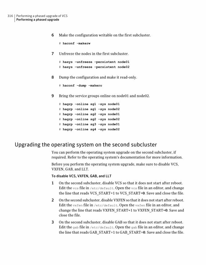
6 Make the configuration writable on the first subcluster.
# haconf -makerw
7 Unfreeze the nodes in the first subcluster.
# hasys -unfreeze -persistent node01
# hasys -unfreeze -persistent node02
8 Dump the configuration and make it read-only.
# haconf -dump -makero
9 Bring the service groups online on node01 and node02.
# hagrp -online sg1 -sys node01
# hagrp -online sg1 -sys node02
# hagrp -online sg2 -sys node01
# hagrp -online sg2 -sys node02
# hagrp -online sg3 -sys node01
# hagrp -online sg4 -sys node02
Upgrading the operating system on the second subclusterYou can perform the operating system upgrade on the second subcluster, ifrequired. Refer to the operating system's documentation for more information.
Before you perform the operating system upgrade, make sure to disable VCS,VXFEN, GAB, and LLT.
To disable VCS, VXFEN, GAB, and LLT
1 On the second subcluster, disable VCS so that it does not start after reboot.Edit the vcs file in /etc/default. Open the vcs file in an editor, and changethe line that reads VCS_START=1 to VCS_START=0. Save and close the file.
2 On the second subcluster, disable VXFEN so that it does not start after reboot.Edit the vxfen file in /etc/default. Open the vxfen file in an editor, andchange the line that reads VXFEN_START=1 to VXFEN_START=0. Save andclose the file.
3 On the second subcluster, disable GAB so that it does not start after reboot.Edit the gab file in /etc/default. Open the gab file in an editor, and changethe line that reads GAB_START=1 to GAB_START=0. Save and close the file.
Performing a phased upgrade of VCSPerforming a phased upgrade
316
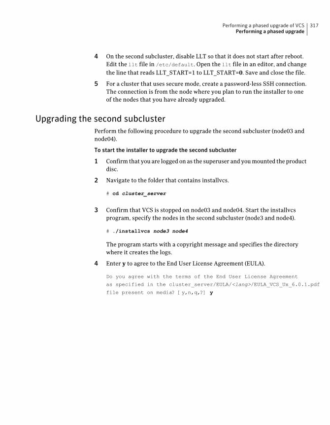
4 On the second subcluster, disable LLT so that it does not start after reboot.Edit the llt file in /etc/default. Open the llt file in an editor, and changethe line that reads LLT_START=1 to LLT_START=0. Save and close the file.
5 For a cluster that uses secure mode, create a password-less SSH connection.The connection is from the node where you plan to run the installer to oneof the nodes that you have already upgraded.
Upgrading the second subclusterPerform the following procedure to upgrade the second subcluster (node03 andnode04).
To start the installer to upgrade the second subcluster
1 Confirm that you are logged on as the superuser and you mounted the productdisc.
2 Navigate to the folder that contains installvcs.
# cd cluster_server
3 Confirm that VCS is stopped on node03 and node04. Start the installvcsprogram, specify the nodes in the second subcluster (node3 and node4).
# ./installvcs node3 node4
The program starts with a copyright message and specifies the directorywhere it creates the logs.
4 Enter y to agree to the End User License Agreement (EULA).
Do you agree with the terms of the End User License Agreement
as specified in the cluster_server/EULA/<lang>/EULA_VCS_Ux_6.0.1.pdf
file present on media? [y,n,q,?] y
317Performing a phased upgrade of VCSPerforming a phased upgrade
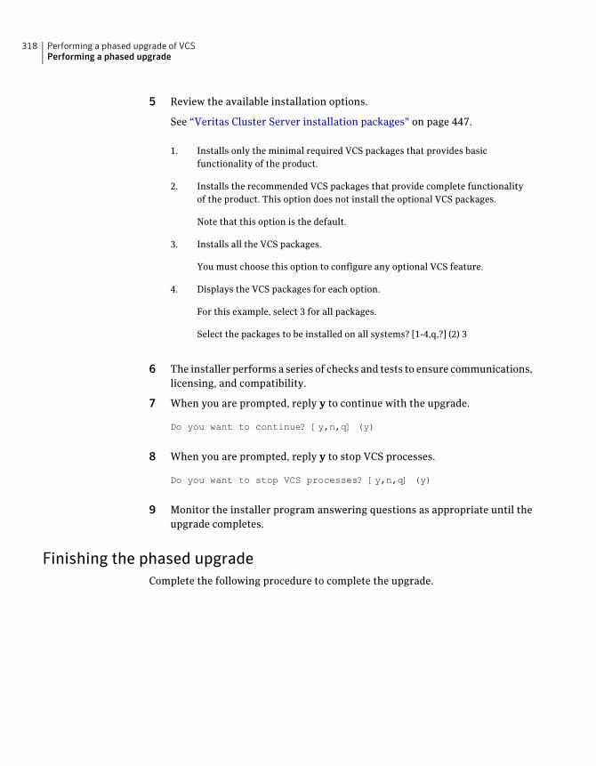
5 Review the available installation options.
See “Veritas Cluster Server installation packages” on page 447.
Installs only the minimal required VCS packages that provides basicfunctionality of the product.
1.
Installs the recommended VCS packages that provide complete functionalityof the product. This option does not install the optional VCS packages.
2.
Note that this option is the default.
Installs all the VCS packages.3.
You must choose this option to configure any optional VCS feature.
Displays the VCS packages for each option.4.
For this example, select 3 for all packages.
Select the packages to be installed on all systems? [1-4,q,?] (2) 3
6 The installer performs a series of checks and tests to ensure communications,licensing, and compatibility.
7 When you are prompted, reply y to continue with the upgrade.
Do you want to continue? [y,n,q] (y)
8 When you are prompted, reply y to stop VCS processes.
Do you want to stop VCS processes? [y,n,q] (y)
9 Monitor the installer program answering questions as appropriate until theupgrade completes.
Finishing the phased upgradeComplete the following procedure to complete the upgrade.
Performing a phased upgrade of VCSPerforming a phased upgrade
318
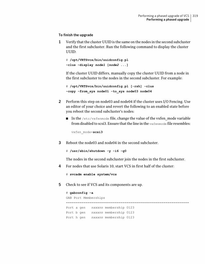
To finish the upgrade
1 Verify that the cluster UUID is the same on the nodes in the second subclusterand the first subcluster. Run the following command to display the clusterUUID:
# /opt/VRTSvcs/bin/uuidconfig.pl
-clus -display node1 [node2 ...]
If the cluster UUID differs, manually copy the cluster UUID from a node inthe first subcluster to the nodes in the second subcluster. For example:
# /opt/VRTSvcs/bin/uuidconfig.pl [-rsh] -clus
-copy -from_sys node01 -to_sys node03 node04
2 Perform this step on node03 and node04 if the cluster uses I/O Fencing. Usean editor of your choice and revert the following to an enabled state beforeyou reboot the second subcluster's nodes:
■ In the /etc/vxfenmode file, change the value of the vxfen_mode variablefrom disabled to scsi3. Ensure that the line in the vxfenmode file resembles:
vxfen_mode=scsi3
3 Reboot the node03 and node04 in the second subcluster.
# /usr/sbin/shutdown -y -i6 -g0
The nodes in the second subcluster join the nodes in the first subcluster.
4 For nodes that use Solaris 10, start VCS in first half of the cluster:
# svcadm enable system/vcs
5 Check to see if VCS and its components are up.
# gabconfig -a
GAB Port Memberships
===============================================================
Port a gen nxxxnn membership 0123
Port b gen nxxxnn membership 0123
Port h gen nxxxnn membership 0123
319Performing a phased upgrade of VCSPerforming a phased upgrade
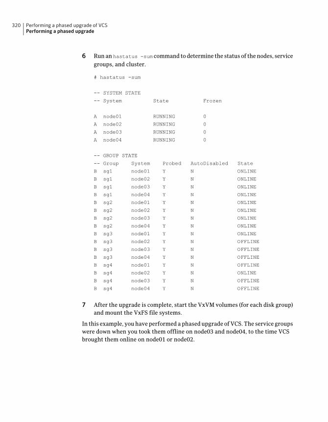
6 Run an hastatus -sum command to determine the status of the nodes, servicegroups, and cluster.
# hastatus -sum
-- SYSTEM STATE
-- System State Frozen
A node01 RUNNING 0
A node02 RUNNING 0
A node03 RUNNING 0
A node04 RUNNING 0
-- GROUP STATE
-- Group System Probed AutoDisabled State
B sg1 node01 Y N ONLINE
B sg1 node02 Y N ONLINE
B sg1 node03 Y N ONLINE
B sg1 node04 Y N ONLINE
B sg2 node01 Y N ONLINE
B sg2 node02 Y N ONLINE
B sg2 node03 Y N ONLINE
B sg2 node04 Y N ONLINE
B sg3 node01 Y N ONLINE
B sg3 node02 Y N OFFLINE
B sg3 node03 Y N OFFLINE
B sg3 node04 Y N OFFLINE
B sg4 node01 Y N OFFLINE
B sg4 node02 Y N ONLINE
B sg4 node03 Y N OFFLINE
B sg4 node04 Y N OFFLINE
7 After the upgrade is complete, start the VxVM volumes (for each disk group)and mount the VxFS file systems.
In this example, you have performed a phased upgrade of VCS. The service groupswere down when you took them offline on node03 and node04, to the time VCSbrought them online on node01 or node02.
Performing a phased upgrade of VCSPerforming a phased upgrade
320

Note: If you want to upgrade Coordination Point (CP) server systems that useVeritas Cluster Server (VCS) or Storage Foundation High Availability (SFHA) to6.0.1, make sure that you upgraded all application clusters to version 6.0.1. Then,upgrade VCS or SFHA on the CP server systems. For instructions to upgrade VCSor SFHA, see the VCS or SFHA Installation Guide.
321Performing a phased upgrade of VCSPerforming a phased upgrade

Performing a phased upgrade of VCSPerforming a phased upgrade
322
Performing an automatedVCS upgrade usingresponse files
This chapter includes the following topics:
■ Upgrading VCS using response files
■ Response file variables to upgrade VCS
■ Sample response file for upgrading VCS
Upgrading VCS using response filesTypically, you can use the response file that the installer generates after youperform VCS upgrade on one system to upgrade VCS on other systems. You canalso create a response file using the makeresponsefile option of the installer.
To perform automated VCS upgrade
1 Make sure the systems where you want to upgrade VCS meet the upgraderequirements.
2 Make sure the pre-upgrade tasks are completed.
3 Copy the response file to one of the systems where you want to upgrade VCS.
See “Sample response file for upgrading VCS” on page 325.
4 Edit the values of the response file variables as necessary.
See “Response file variables to upgrade VCS” on page 324.
22Chapter
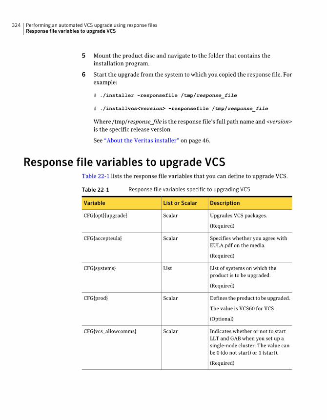
5 Mount the product disc and navigate to the folder that contains theinstallation program.
6 Start the upgrade from the system to which you copied the response file. Forexample:
# ./installer -responsefile /tmp/response_file
# ./installvcs<version> -responsefile /tmp/response_file
Where /tmp/response_file is the response file’s full path name and <version>is the specific release version.
See “About the Veritas installer” on page 46.
Response file variables to upgrade VCSTable 22-1 lists the response file variables that you can define to upgrade VCS.
Table 22-1 Response file variables specific to upgrading VCS
DescriptionList or ScalarVariable
Upgrades VCS packages.
(Required)
ScalarCFG{opt}{upgrade}
Specifies whether you agree withEULA.pdf on the media.
(Required)
ScalarCFG{accepteula}
List of systems on which theproduct is to be upgraded.
(Required)
ListCFG{systems}
Defines the product to be upgraded.
The value is VCS60 for VCS.
(Optional)
ScalarCFG{prod}
Indicates whether or not to startLLT and GAB when you set up asingle-node cluster. The value canbe 0 (do not start) or 1 (start).
(Required)
ScalarCFG{vcs_allowcomms}
Performing an automated VCS upgrade using response filesResponse file variables to upgrade VCS
324
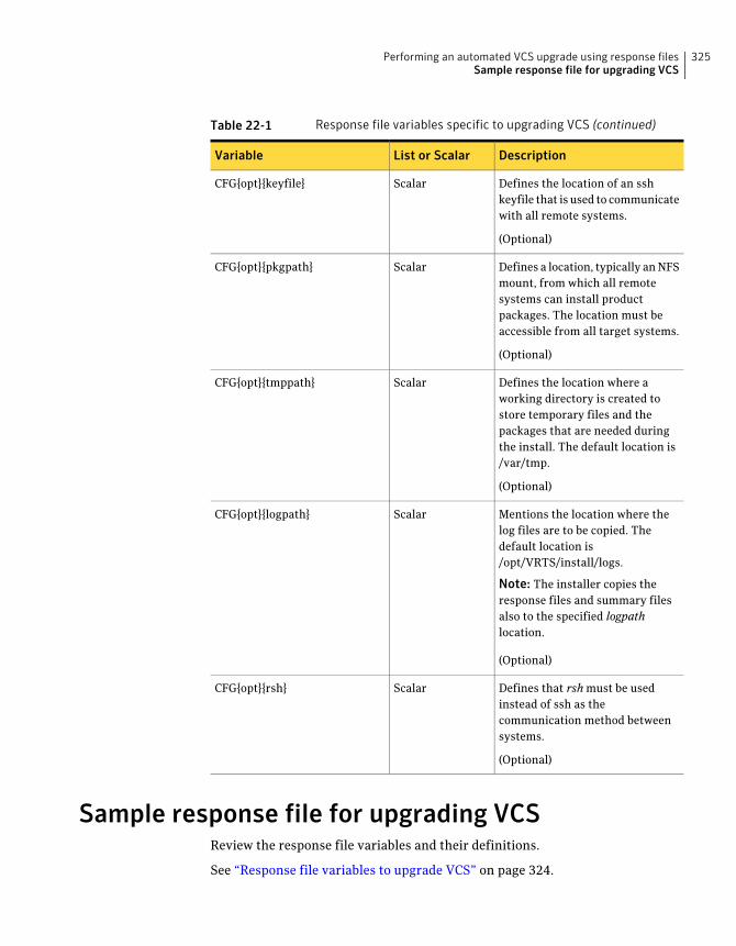
Table 22-1 Response file variables specific to upgrading VCS (continued)
DescriptionList or ScalarVariable
Defines the location of an sshkeyfile that is used to communicatewith all remote systems.
(Optional)
ScalarCFG{opt}{keyfile}
Defines a location, typically an NFSmount, from which all remotesystems can install productpackages. The location must beaccessible from all target systems.
(Optional)
ScalarCFG{opt}{pkgpath}
Defines the location where aworking directory is created tostore temporary files and thepackages that are needed duringthe install. The default location is/var/tmp.
(Optional)
ScalarCFG{opt}{tmppath}
Mentions the location where thelog files are to be copied. Thedefault location is/opt/VRTS/install/logs.
Note: The installer copies theresponse files and summary filesalso to the specified logpathlocation.
(Optional)
ScalarCFG{opt}{logpath}
Defines that rsh must be usedinstead of ssh as thecommunication method betweensystems.
(Optional)
ScalarCFG{opt}{rsh}
Sample response file for upgrading VCSReview the response file variables and their definitions.
See “Response file variables to upgrade VCS” on page 324.
325Performing an automated VCS upgrade using response filesSample response file for upgrading VCS
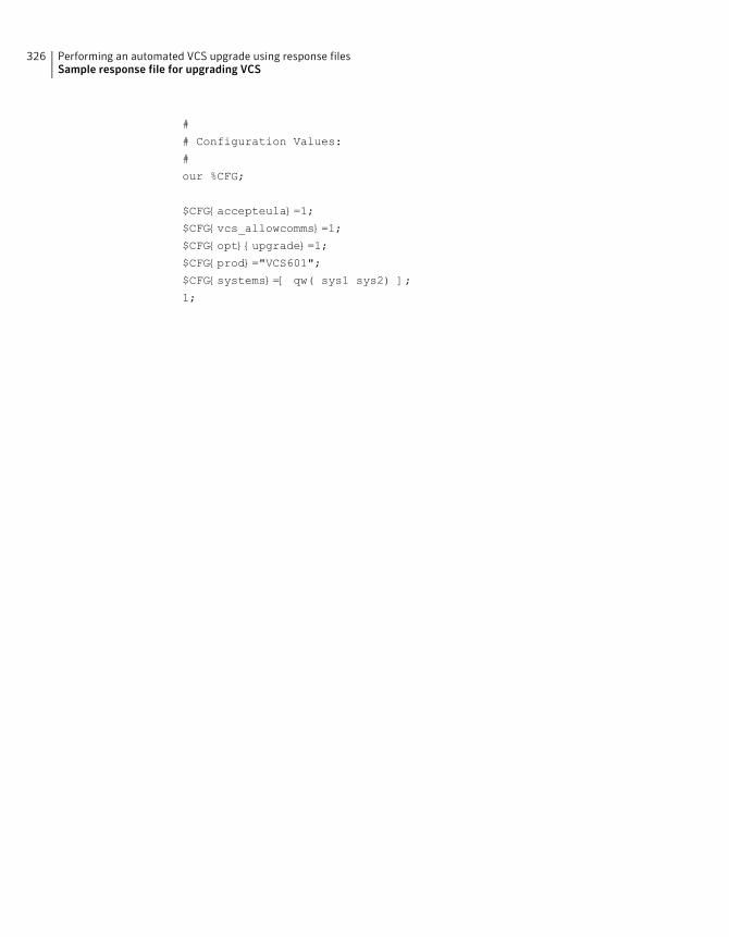
#
# Configuration Values:
#
our %CFG;
$CFG{accepteula}=1;
$CFG{vcs_allowcomms}=1;
$CFG{opt}{upgrade}=1;
$CFG{prod}="VCS601";
$CFG{systems}=[ qw( sys1 sys2) ];
1;
Performing an automated VCS upgrade using response filesSample response file for upgrading VCS
326
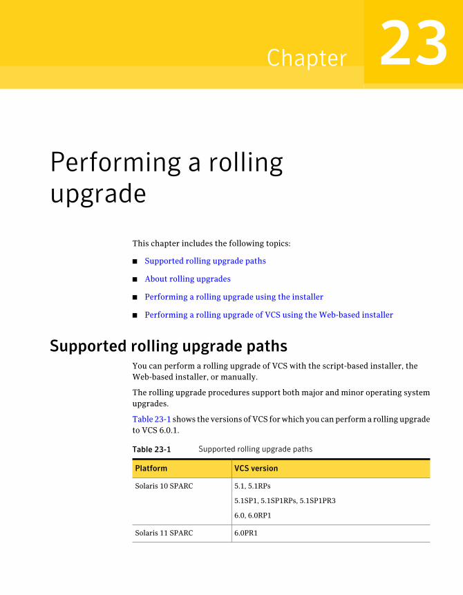
Performing a rollingupgrade
This chapter includes the following topics:
■ Supported rolling upgrade paths
■ About rolling upgrades
■ Performing a rolling upgrade using the installer
■ Performing a rolling upgrade of VCS using the Web-based installer
Supported rolling upgrade pathsYou can perform a rolling upgrade of VCS with the script-based installer, theWeb-based installer, or manually.
The rolling upgrade procedures support both major and minor operating systemupgrades.
Table 23-1 shows the versions of VCS for which you can perform a rolling upgradeto VCS 6.0.1.
Table 23-1 Supported rolling upgrade paths
VCS versionPlatform
5.1, 5.1RPs
5.1SP1, 5.1SP1RPs, 5.1SP1PR3
6.0, 6.0RP1
Solaris 10 SPARC
6.0PR1Solaris 11 SPARC
23Chapter
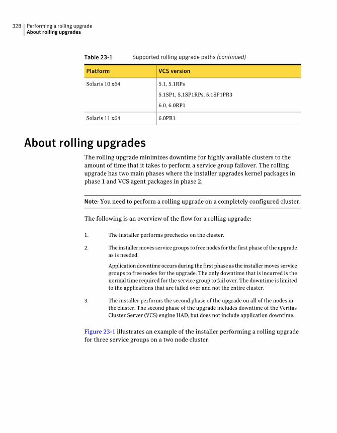
Table 23-1 Supported rolling upgrade paths (continued)
VCS versionPlatform
5.1, 5.1RPs
5.1SP1, 5.1SP1RPs, 5.1SP1PR3
6.0, 6.0RP1
Solaris 10 x64
6.0PR1Solaris 11 x64
About rolling upgradesThe rolling upgrade minimizes downtime for highly available clusters to theamount of time that it takes to perform a service group failover. The rollingupgrade has two main phases where the installer upgrades kernel packages inphase 1 and VCS agent packages in phase 2.
Note: You need to perform a rolling upgrade on a completely configured cluster.
The following is an overview of the flow for a rolling upgrade:
The installer performs prechecks on the cluster.1.
The installer moves service groups to free nodes for the first phase of the upgradeas is needed.
Application downtime occurs during the first phase as the installer moves servicegroups to free nodes for the upgrade. The only downtime that is incurred is thenormal time required for the service group to fail over. The downtime is limitedto the applications that are failed over and not the entire cluster.
2.
The installer performs the second phase of the upgrade on all of the nodes inthe cluster. The second phase of the upgrade includes downtime of the VeritasCluster Server (VCS) engine HAD, but does not include application downtime.
3.
Figure 23-1 illustrates an example of the installer performing a rolling upgradefor three service groups on a two node cluster.
Performing a rolling upgradeAbout rolling upgrades
328
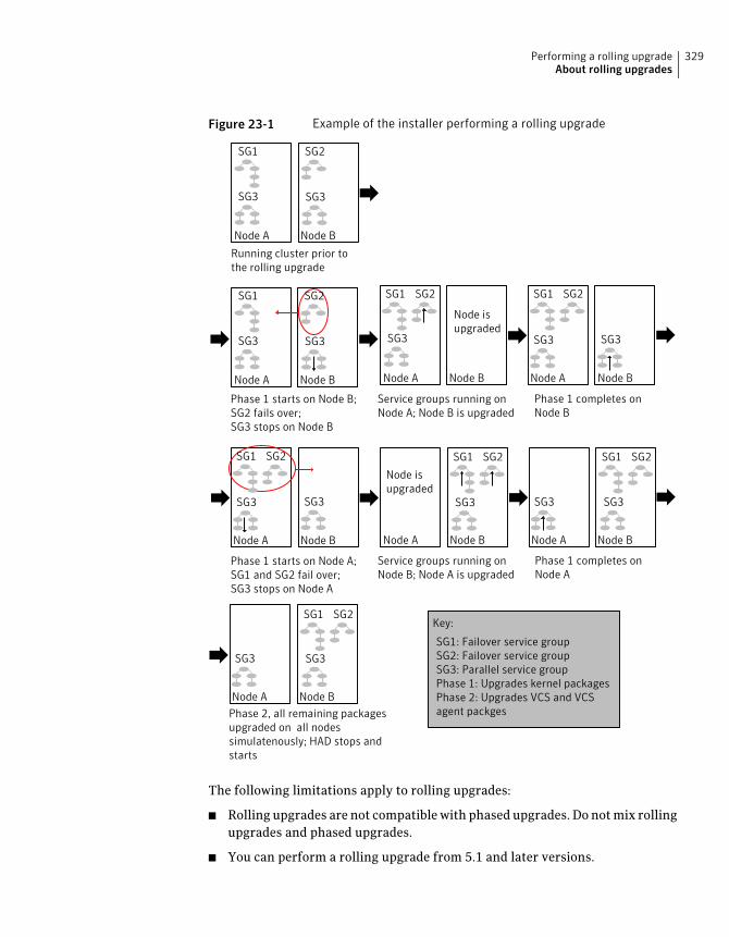
Figure 23-1 Example of the installer performing a rolling upgrade
Phase 1 starts on Node B;SG2 fails over;SG3 stops on Node B
Phase 2, all remaining packagesupgraded on all nodessimulatenously; HAD stops andstarts
SG1: Failover service groupSG2: Failover service groupSG3: Parallel service groupPhase 1: Upgrades kernel packagesPhase 2: Upgrades VCS and VCSagent packges
Node A Node B
SG3 SG3
SG1 SG2
Phase 1 completes onNode B
Phase 1 starts on Node A;SG1 and SG2 fail over;SG3 stops on Node A
Service groups running onNode A; Node B is upgraded
Phase 1 completes onNode A
Running cluster prior tothe rolling upgrade
Node A Node B
SG3 SG3
SG1 SG2
Node A Node B
SG1 SG2
SG3SG3
Node A Node B
SG3 SG3
SG1 SG2
Node A Node B
SG1 SG2
SG3SG3
Service groups running onNode B; Node A is upgraded
Node A Node B
SG3 SG3
SG1 SG2
Node isupgraded
Node A Node B
SG3
SG1 SG2
Node A Node B
SG1 SG2
SG3
Node isupgraded
Key:
The following limitations apply to rolling upgrades:
■ Rolling upgrades are not compatible with phased upgrades. Do not mix rollingupgrades and phased upgrades.
■ You can perform a rolling upgrade from 5.1 and later versions.
329Performing a rolling upgradeAbout rolling upgrades
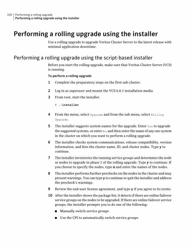
Performing a rolling upgrade using the installerUse a rolling upgrade to upgrade Veritas Cluster Server to the latest release withminimal application downtime.
Performing a rolling upgrade using the script-based installerBefore you start the rolling upgrade, make sure that Veritas Cluster Server (VCS)is running.
To perform a rolling upgrade
1 Complete the preparatory steps on the first sub-cluster.
2 Log in as superuser and mount the VCS 6.0.1 installation media.
3 From root, start the installer.
# ./installer
4 From the menu, select Upgrade and from the sub menu, select RollingUpgrade.
5 The installer suggests system names for the upgrade. Enter Yes to upgradethe suggested systems, or enter No, and then enter the name of any one systemin the cluster on which you want to perform a rolling upgrade.
6 The installer checks system communications, release compatibility, versioninformation, and lists the cluster name, ID, and cluster nodes. Type y tocontinue.
7 The installer inventories the running service groups and determines the nodeor nodes to upgrade in phase 1 of the rolling upgrade. Type y to continue. Ifyou choose to specify the nodes, type n and enter the names of the nodes.
8 The installer performs further prechecks on the nodes in the cluster and maypresent warnings. You can type y to continue or quit the installer and addressthe precheck's warnings.
9 Review the end-user license agreement, and type y if you agree to its terms.
10 After the installer shows the package list, it detects if there are online failoverservice groups on the nodes to be upgraded. If there are online failover servicegroups, the installer prompts you to do one of the following:
■ Manually switch service groups
■ Use the CPI to automatically switch service groups
Performing a rolling upgradePerforming a rolling upgrade using the installer
330
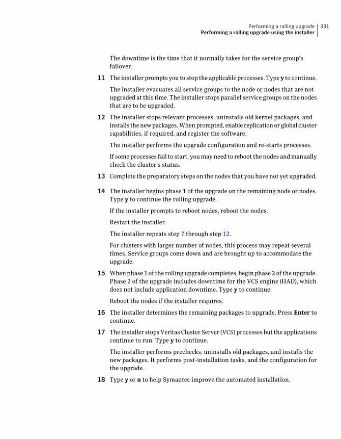
The downtime is the time that it normally takes for the service group'sfailover.
11 The installer prompts you to stop the applicable processes. Type y to continue.
The installer evacuates all service groups to the node or nodes that are notupgraded at this time. The installer stops parallel service groups on the nodesthat are to be upgraded.
12 The installer stops relevant processes, uninstalls old kernel packages, andinstalls the new packages. When prompted, enable replication or global clustercapabilities, if required, and register the software.
The installer performs the upgrade configuration and re-starts processes.
If some processes fail to start, you may need to reboot the nodes and manuallycheck the cluster's status.
13 Complete the preparatory steps on the nodes that you have not yet upgraded.
14 The installer begins phase 1 of the upgrade on the remaining node or nodes.Type y to continue the rolling upgrade.
If the installer prompts to reboot nodes, reboot the nodes.
Restart the installer.
The installer repeats step 7 through step 12.
For clusters with larger number of nodes, this process may repeat severaltimes. Service groups come down and are brought up to accommodate theupgrade.
15 When phase 1 of the rolling upgrade completes, begin phase 2 of the upgrade.Phase 2 of the upgrade includes downtime for the VCS engine (HAD), whichdoes not include application downtime. Type y to continue.
Reboot the nodes if the installer requires.
16 The installer determines the remaining packages to upgrade. Press Enter tocontinue.
17 The installer stops Veritas Cluster Server (VCS) processes but the applicationscontinue to run. Type y to continue.
The installer performs prechecks, uninstalls old packages, and installs thenew packages. It performs post-installation tasks, and the configuration forthe upgrade.
18 Type y or n to help Symantec improve the automated installation.
331Performing a rolling upgradePerforming a rolling upgrade using the installer
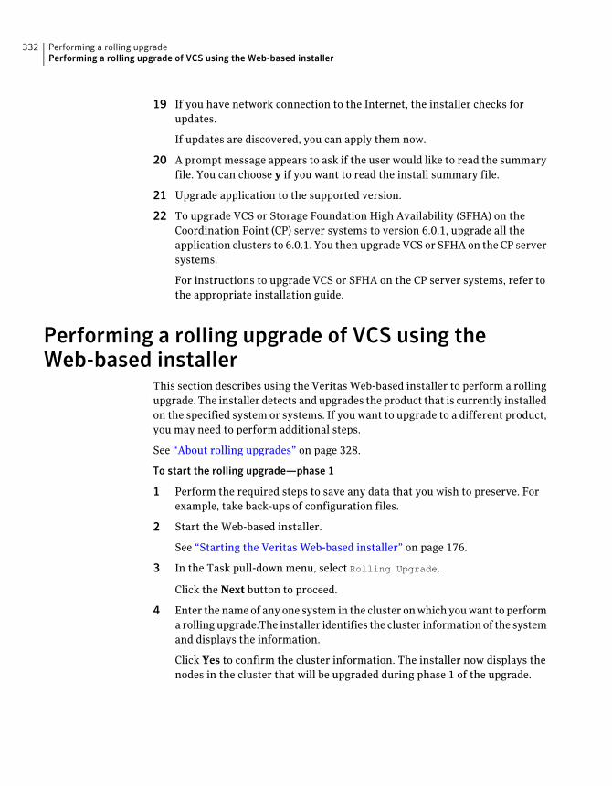
19 If you have network connection to the Internet, the installer checks forupdates.
If updates are discovered, you can apply them now.
20 A prompt message appears to ask if the user would like to read the summaryfile. You can choose y if you want to read the install summary file.
21 Upgrade application to the supported version.
22 To upgrade VCS or Storage Foundation High Availability (SFHA) on theCoordination Point (CP) server systems to version 6.0.1, upgrade all theapplication clusters to 6.0.1. You then upgrade VCS or SFHA on the CP serversystems.
For instructions to upgrade VCS or SFHA on the CP server systems, refer tothe appropriate installation guide.
Performing a rolling upgrade of VCS using theWeb-based installer
This section describes using the Veritas Web-based installer to perform a rollingupgrade. The installer detects and upgrades the product that is currently installedon the specified system or systems. If you want to upgrade to a different product,you may need to perform additional steps.
See “About rolling upgrades” on page 328.
To start the rolling upgrade—phase 1
1 Perform the required steps to save any data that you wish to preserve. Forexample, take back-ups of configuration files.
2 Start the Web-based installer.
See “Starting the Veritas Web-based installer” on page 176.
3 In the Task pull-down menu, select Rolling Upgrade.
Click the Next button to proceed.
4 Enter the name of any one system in the cluster on which you want to performa rolling upgrade.The installer identifies the cluster information of the systemand displays the information.
Click Yes to confirm the cluster information. The installer now displays thenodes in the cluster that will be upgraded during phase 1 of the upgrade.
Performing a rolling upgradePerforming a rolling upgrade of VCS using the Web-based installer
332
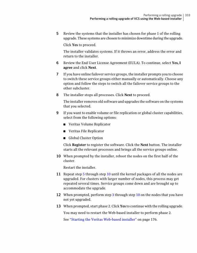
5 Review the systems that the installer has chosen for phase 1 of the rollingupgrade. These systems are chosen to minimize downtime during the upgrade.
Click Yes to proceed.
The installer validates systems. If it throws an error, address the error andreturn to the installer.
6 Review the End User License Agreement (EULA). To continue, select Yes, Iagree and click Next.
7 If you have online failover service groups, the installer prompts you to chooseto switch these service groups either manually or automatically. Choose anyoption and follow the steps to switch all the failover service groups to theother subcluster.
8 The installer stops all processes. Click Next to proceed.
The installer removes old software and upgrades the software on the systemsthat you selected.
9 If you want to enable volume or file replication or global cluster capabilities,select from the following options:
■ Veritas Volume Replicator
■ Veritas File Replicator
■ Global Cluster Option
Click Register to register the software. Click the Next button. The installerstarts all the relevant processes and brings all the service groups online.
10 When prompted by the installer, reboot the nodes on the first half of thecluster.
Restart the installer.
11 Repeat step 5 through step 10 until the kernel packages of all the nodes areupgraded. For clusters with larger number of nodes, this process may getrepeated several times. Service groups come down and are brought up toaccommodate the upgrade.
12 When prompted, perform step 3 through step 10 on the nodes that you havenot yet upgraded.
13 When prompted, start phase 2. Click Yes to continue with the rolling upgrade.
You may need to restart the Web-based installer to perform phase 2.
See “Starting the Veritas Web-based installer” on page 176.
333Performing a rolling upgradePerforming a rolling upgrade of VCS using the Web-based installer

To upgrade the non-kernel components—phase 2
1 In the Task pull-down menu, make sure that Rolling Upgrade is selected.
Click the Next button to proceed.
2 The installer detects the information of cluster and the state of rollingupgrade.
The installer validates systems. Click Next. If it throws an error, address theerror and return to the installer.
3 Review the End User License Agreement (EULA). To continue, select Yes, Iagree and click Next.
4 The installer stops the HAD and CmdServer processes in phase 2 of the rollingupgrade process. Click Next to proceed.
5 The installer removes old software and upgrades the software on the systemsthat you selected. Review the output and click the Next button when prompted.Register the software and click Next to proceed. The installer starts all therelevant processes and brings all the service groups online.
6 If you have network connection to the Internet, the installer checks forupdates.
If updates are discovered, you can apply them now.
7 A prompt message appears to ask if the user would like to read the summaryfile. You can choose y if you want to read the install summary file.
The upgrade is complete.
Performing a rolling upgradePerforming a rolling upgrade of VCS using the Web-based installer
334
Upgrading using LiveUpgrade
This chapter includes the following topics:
■ About Live Upgrade
■ Supported upgrade paths for Live Upgrade
■ Before you upgrade VCS using Solaris Live Upgrade
■ Upgrading VCS and Solaris using Live Upgrade
■ Upgrading Solaris using Live Upgrade
■ Upgrading VCS using Live Upgrade
■ Administering boot environments
About Live UpgradeYou can use Live Upgrade on Solaris 10 systems to perform the following typesof upgrade:
■ Upgrade the operating system and VCS.See “Upgrading VCS and Solaris using Live Upgrade” on page 340.
■ Upgrade the operating system.See “Upgrading Solaris using Live Upgrade” on page 347.
■ Upgrade VCS.See “Upgrading VCS using Live Upgrade” on page 349.
Figure 24-1 illustrates an example of an upgrade of Veritas products from 5.1 SP1to 6.0.1, and the operating system from Solaris 9 to Solaris 10.
24Chapter
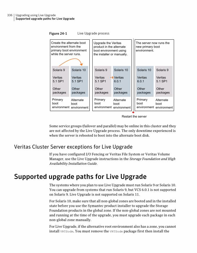
Figure 24-1 Live Upgrade process
Create the alternate bootenvironment from theprimary boot environmentwhile the server runs.
Solaris 9
Veritas5.1 SP1
Otherpackages
Solaris 10
Veritas5.1 SP1
Otherpackages
Primarybootenvironment
Alternatebootenvironment
The server now runs thenew primary bootenvironment.
Solaris 10
Veritas6.0.1
Otherpackages
Solaris 9
Veritas5.1 SP1
Otherpackages
Primarybootenvironment
Alternatebootenvironment
Upgrade the Veritasproduct in the alternateboot environment usingthe installer or manually.
Solaris 9
Veritas5.1 SP1
Otherpackages
Solaris 10
Veritas6.0.1
Otherpackages
Primarybootenvironment
Alternatebootenvironment
Restart the server
Upgrade the Veritasproduct in the alternateboot environment usingthe installer or manually.
Some service groups (failover and parallel) may be online in this cluster and theyare not affected by the Live Upgrade process. The only downtime experienced iswhen the server is rebooted to boot into the alternate boot disk.
Veritas Cluster Server exceptions for Live UpgradeIf you have configured I/O Fencing or Veritas File System or Veritas VolumeManager, use the Live Upgrade instructions in the Storage Foundation and HighAvailability Installation Guide.
Supported upgrade paths for Live UpgradeThe systems where you plan to use Live Upgrade must run Solaris 9 or Solaris 10.You can upgrade from systems that run Solaris 9, but VCS 6.0.1 is not supportedon Solaris 9. Live Upgrade is not supported on Solaris 11.
For Solaris 10, make sure that all non-global zones are booted and in the installedstate before you use the Symantec product installer to upgrade the StorageFoundation products in the global zone. If the non-global zones are not mountedand running at the time of the upgrade, you must upgrade each package in eachnon-global zone manually.
For Live Upgrade, if the alternative root environment also has a zone, you cannotinstall VRTSodm. You must remove the VRTSodm package first then install the
Upgrading using Live UpgradeSupported upgrade paths for Live Upgrade
336
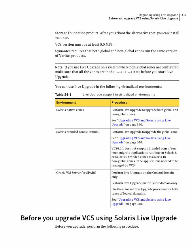
Storage Foundation product. After you reboot the alternative root, you can installVRTSodm.
VCS version must be at least 5.0 MP3.
Symantec requires that both global and non-global zones run the same versionof Veritas products.
Note: If you use Live Upgrade on a system where non-global zones are configured,make sure that all the zones are in the installed state before you start LiveUpgrade.
You can use Live Upgrade in the following virtualized environments:
Table 24-1 Live Upgrade support in virtualized environments
ProcedureEnvironment
Perform Live Upgrade to upgrade both global andnon-global zones.
See “Upgrading VCS and Solaris using LiveUpgrade” on page 340.
Solaris native zones
Perform Live Upgrade to upgrade the global zone.
See “Upgrading VCS and Solaris using LiveUpgrade” on page 340.
VCS6.0.1 does not support Branded zones. Youmust migrate applications running on Solaris 8or Solaris 9 branded zones to Solaris 10non-global zones if the applications needed to bemanaged by VCS.
Solaris branded zones (BrandZ)
Perform Live Upgrade on the Control domainonly.
Perform Live Upgrade on the Guest domain only.
Use the standard Live Upgrade procedure for bothtypes of logical domains.
See “Upgrading VCS and Solaris using LiveUpgrade” on page 340.
Oracle VM Server for SPARC
Before you upgrade VCS using Solaris Live UpgradeBefore you upgrade, perform the following procedure.
337Upgrading using Live UpgradeBefore you upgrade VCS using Solaris Live Upgrade
To prepare for the Live Upgrade
1 Make sure that the VCS installation media and the operating systeminstallation images are available and on hand.
2 On the nodes to be upgraded, select an alternate boot disk that is at least thesame size as the root partition of the primary boot disk.
If the primary boot disk is mirrored, you need to break off the mirror for thealternate boot disk.
3 Before you perform the Live Upgrade, take offline any services that involvenon-root file systems. This prevents file systems from being copied to thealternate boot environment that could potentially cause a root file system torun out of space.
4 On the primary boot disk, patch the operating system for Live Upgrade. Patch137477-01 is required. Verify that this patch is installed.
5 The version of the Live Upgrade packages must match the version of theoperating system to which you want to upgrade on the alternate boot disk.If you are upgrading the Solaris operating system, do the following steps:
■ Remove the installed Live Upgrade packages for the current operatingsystem version:All Solaris versions: SUNWluu, SUNWlur packages.Solaris 10 update 7 or later also requires: SUNWlucfg package.Solaris 10 zones or Branded zones also requires: SUNWluzone package.
■ From the new Solaris installation image, install the new versions of thefollowing Live Upgrade packages:All Solaris versions: SUNWluu, SUNWlur, and SUNWlucfg packages.Solaris 10 zones or Branded zones also requires: SUNWluzone package.
Note: While you can perform Live Upgrade in the presence of brandedzones, they must be halted, and the branded zones themselves are notupgraded.
Solaris installation media comes with a script for this purpose namedliveupgrade20. Find the script at/cdrom/solaris_release/Tools/Installers/liveupgrade20. If scripting, you canuse:
# /cdrom/solaris_release/Tools/Installers/liveupgrade20 \
-nodisplay -noconsole
Upgrading using Live UpgradeBefore you upgrade VCS using Solaris Live Upgrade
338
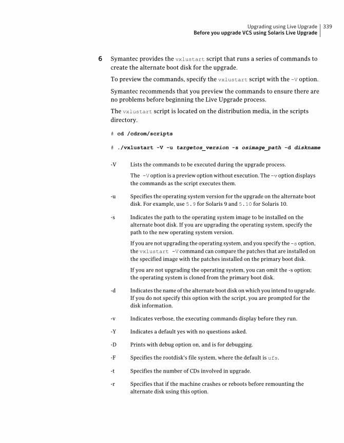
6 Symantec provides the vxlustart script that runs a series of commands tocreate the alternate boot disk for the upgrade.
To preview the commands, specify the vxlustart script with the -V option.
Symantec recommends that you preview the commands to ensure there areno problems before beginning the Live Upgrade process.
The vxlustart script is located on the distribution media, in the scriptsdirectory.
# cd /cdrom/scripts
# ./vxlustart -V -u targetos_version -s osimage_path -d diskname
Lists the commands to be executed during the upgrade process.-V
The -V option is a preview option without execution. The-v option displaysthe commands as the script executes them.
Specifies the operating system version for the upgrade on the alternate bootdisk. For example, use 5.9 for Solaris 9 and 5.10 for Solaris 10.
-u
Indicates the path to the operating system image to be installed on thealternate boot disk. If you are upgrading the operating system, specify thepath to the new operating system version.
-s
If you are not upgrading the operating system, and you specify the-s option,the vxlustart -V command can compare the patches that are installed onthe specified image with the patches installed on the primary boot disk.
If you are not upgrading the operating system, you can omit the -s option;the operating system is cloned from the primary boot disk.
Indicates the name of the alternate boot disk on which you intend to upgrade.If you do not specify this option with the script, you are prompted for thedisk information.
-d
Indicates verbose, the executing commands display before they run.-v
Indicates a default yes with no questions asked.-Y
Prints with debug option on, and is for debugging.-D
Specifies the rootdisk's file system, where the default is ufs.-F
Specifies the number of CDs involved in upgrade.-t
Specifies that if the machine crashes or reboots before remounting thealternate disk using this option.
-r
339Upgrading using Live UpgradeBefore you upgrade VCS using Solaris Live Upgrade
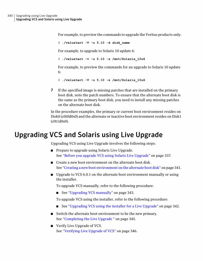
For example, to preview the commands to upgrade the Veritas products only:
# ./vxlustart -V -u 5.10 -d disk_name
For example, to upgrade to Solaris 10 update 6:
# ./vxlustart -v -u 5.10 -s /mnt/Solaris_10u6
For example, to preview the commands for an upgrade to Solaris 10 update6:
# ./vxlustart -V -u 5.10 -s /mnt/Solaris_10u6
7 If the specified image is missing patches that are installed on the primaryboot disk, note the patch numbers. To ensure that the alternate boot disk isthe same as the primary boot disk, you need to install any missing patcheson the alternate boot disk.
In the procedure examples, the primary or current boot environment resides onDisk0 (c0t0d0s0) and the alternate or inactive boot environment resides on Disk1(c0t1d0s0).
Upgrading VCS and Solaris using Live UpgradeUpgrading VCS using Live Upgrade involves the following steps:
■ Prepare to upgrade using Solaris Live Upgrade.See “Before you upgrade VCS using Solaris Live Upgrade” on page 337.
■ Create a new boot environment on the alternate boot disk.See “Creating a new boot environment on the alternate boot disk” on page 341.
■ Upgrade to VCS 6.0.1 on the alternate boot environment manually or usingthe installer.
To upgrade VCS manually, refer to the following procedure:
■ See “Upgrading VCS manually” on page 343.
To upgrade VCS using the installer, refer to the following procedure:
■ See “Upgrading VCS using the installer for a Live Upgrade” on page 342.
■ Switch the alternate boot environment to be the new primary.See “Completing the Live Upgrade ” on page 345.
■ Verify Live Upgrade of VCS.See “Verifying Live Upgrade of VCS” on page 346.
Upgrading using Live UpgradeUpgrading VCS and Solaris using Live Upgrade
340

Creating a new boot environment on the alternate boot diskRun the vxlustart command on each node in the cluster to create a new bootenvironment on the alternate boot disk.
Note: This step can take several hours to complete. Do not interrupt the sessionas it may leave the boot environment unstable.
At the end of the process:
■ The Solaris operating system on the alternate boot disk is upgraded, if youhave chosen to upgrade the operating system.
■ A new boot environment is created on the alternate boot disk by cloning theprimary boot environment.
To create a new boot environment on the alternate boot disk
Perform the steps in this procedure on each node in the cluster.
1 Navigate to the install media for the Symantec products:
# cd /cdrom/scripts
2 View the list of VxVM disks on which you want to create the new bootenvironment.
# vxdisk list
341Upgrading using Live UpgradeUpgrading VCS and Solaris using Live Upgrade
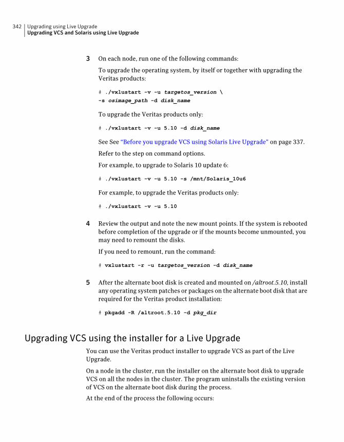
3 On each node, run one of the following commands:
To upgrade the operating system, by itself or together with upgrading theVeritas products:
# ./vxlustart -v -u targetos_version \
-s osimage_path -d disk_name
To upgrade the Veritas products only:
# ./vxlustart -v -u 5.10 -d disk_name
See See “Before you upgrade VCS using Solaris Live Upgrade” on page 337.
Refer to the step on command options.
For example, to upgrade to Solaris 10 update 6:
# ./vxlustart -v -u 5.10 -s /mnt/Solaris_10u6
For example, to upgrade the Veritas products only:
# ./vxlustart -v -u 5.10
4 Review the output and note the new mount points. If the system is rebootedbefore completion of the upgrade or if the mounts become unmounted, youmay need to remount the disks.
If you need to remount, run the command:
# vxlustart -r -u targetos_version -d disk_name
5 After the alternate boot disk is created and mounted on /altroot.5.10, installany operating system patches or packages on the alternate boot disk that arerequired for the Veritas product installation:
# pkgadd -R /altroot.5.10 -d pkg_dir
Upgrading VCS using the installer for a Live UpgradeYou can use the Veritas product installer to upgrade VCS as part of the LiveUpgrade.
On a node in the cluster, run the installer on the alternate boot disk to upgradeVCS on all the nodes in the cluster. The program uninstalls the existing versionof VCS on the alternate boot disk during the process.
At the end of the process the following occurs:
Upgrading using Live UpgradeUpgrading VCS and Solaris using Live Upgrade
342
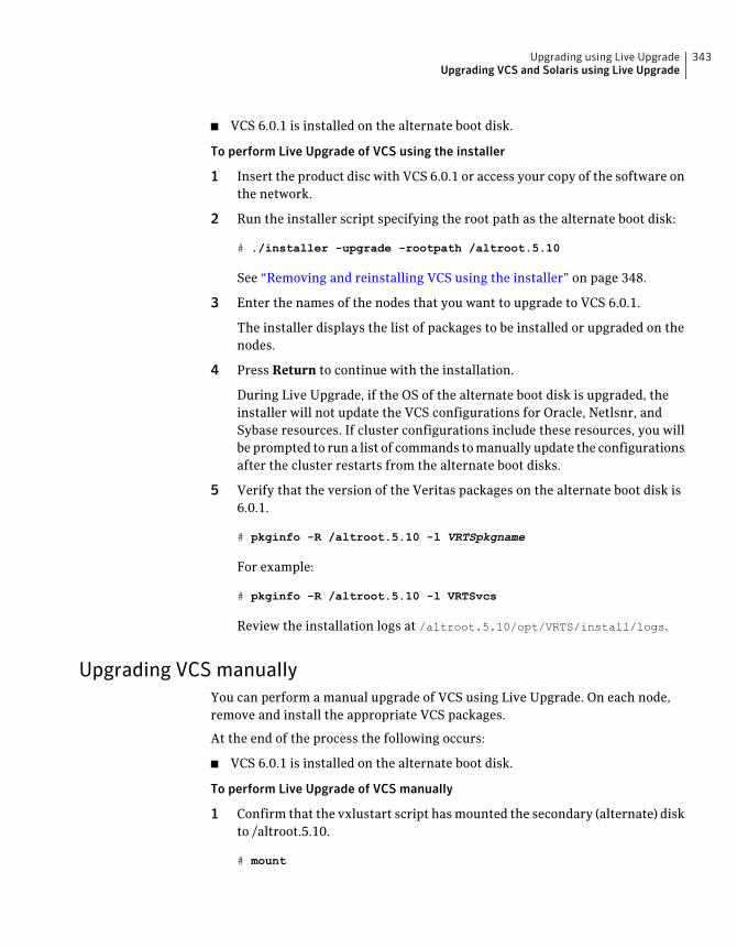
■ VCS 6.0.1 is installed on the alternate boot disk.
To perform Live Upgrade of VCS using the installer
1 Insert the product disc with VCS 6.0.1 or access your copy of the software onthe network.
2 Run the installer script specifying the root path as the alternate boot disk:
# ./installer -upgrade -rootpath /altroot.5.10
See “Removing and reinstalling VCS using the installer” on page 348.
3 Enter the names of the nodes that you want to upgrade to VCS 6.0.1.
The installer displays the list of packages to be installed or upgraded on thenodes.
4 Press Return to continue with the installation.
During Live Upgrade, if the OS of the alternate boot disk is upgraded, theinstaller will not update the VCS configurations for Oracle, Netlsnr, andSybase resources. If cluster configurations include these resources, you willbe prompted to run a list of commands to manually update the configurationsafter the cluster restarts from the alternate boot disks.
5 Verify that the version of the Veritas packages on the alternate boot disk is6.0.1.
# pkginfo -R /altroot.5.10 -l VRTSpkgname
For example:
# pkginfo -R /altroot.5.10 -l VRTSvcs
Review the installation logs at /altroot.5.10/opt/VRTS/install/logs.
Upgrading VCS manuallyYou can perform a manual upgrade of VCS using Live Upgrade. On each node,remove and install the appropriate VCS packages.
At the end of the process the following occurs:
■ VCS 6.0.1 is installed on the alternate boot disk.
To perform Live Upgrade of VCS manually
1 Confirm that the vxlustart script has mounted the secondary (alternate) diskto /altroot.5.10.
# mount
343Upgrading using Live UpgradeUpgrading VCS and Solaris using Live Upgrade
Or
# df -k
2 Remove VCS packages on the alternate boot disk in the following order:
# pkgrm -R /altroot.5.10 \
VRTScmcc VRTScmcs VRTScssim VRTScscm \
VRTSvcsmn VRTSacclib VRTSweb VRTScscw \
VRTSjre15 VRTSvcsag VRTSvcsmg VRTSvcs \
VRTSvxfen VRTSgab VRTSllt VRTSspt VRTSat \
VRTSpbx VRTSicsco VRTSvlic VRTSperl
The -R option removes the packages from the root path /altroot.5.10.
Package lists vary from release to release.
3 Install the VCS packages in the following order one at a time to the alternateboot disk using thepkgadd command. Note that this package list is an example.Full package lists vary from release to release and by product option.
VRTSvlic.pkg VRTSperl.pkg VRTSspt.pkg VRTSat.pkg
VRTSllt.pkg VRTSgab.pkg VRTSvxfen.pkg VRTSamf.pkg
VRTSvcs.pkg VRTScps.pkg VRTSvcsag.pkg VRTSvcsea.pkg
For example:
# pkgadd -R /altroot.5.10 -d package_name.pkg
where you replace package_name.pkg with a package's name, for exampleVRTSvcs.pkg.
# pkgadd -R /altroot.5.10 -d VRTSvcs.pkg
4 In the /mediadirectory, list the patches for each platform. Enter the following:
# ./installer -listpatches
5 Unzip and extract the tar file for each patch.
# gunzip patch_name.tar.gz
# tar vxf patch_name.tar
where patch_name is the name of a patch listed in step 4.
For example:
Upgrading using Live UpgradeUpgrading VCS and Solaris using Live Upgrade
344
# gunzip 143282-01.tar.gz
# tar vxf 143282-01.tar
Repeat this step for each patch.
6 Install the patches on the alternative boot disk using the patchadd command.
# patchadd -R /altroot.5.10 patch_name
For example:
# patchadd -R /altroot.5.10 143282-01
7 Verify that the version of the packages on the alternate boot disk is 6.0.1.
# pkginfo -R /altroot.5.10 -l VRTSvcs
8 Run the following command to export the root path installation environmentvariable.
# export INSTALL_ROOT_PATH=/altroot.5.10
9 Run the following command on the alternate root path of any one node inthe cluster to configure a VCS cluster UUID:
# /altroot.5.10/opt/VRTSvcs/bin/uuidconfig.pl -clus -configure \
-use_llthost
The -use_llthost option indicates that the /etc/llthost file is used todetermine the names of the nodes in the cluster. Alternatively, you can specifythe node names instead of the file name.
10 Confirm that you have created the Universal Unique Identifier:
# /altroot.5.10/opt/VRTSvcs/bin/uuidconfig.pl -clus -display \
-use_llthost
Completing the Live UpgradeAt the end of the process:
■ The alternate boot environment is activated.
■ The system is booted from the alternate boot disk.
345Upgrading using Live UpgradeUpgrading VCS and Solaris using Live Upgrade
To complete the Live Upgrade
1 Complete the Live upgrade process. Enter the following command on all nodesin the cluster.
# ./vcslufinish -u target_os_version
Live Upgrade finish on the Solaris release <5.10>
2 If the system crashes or reboots before Live Upgrade completes successfully,you can remount the alternate disk using the following command:
# ./vxlustart -r -u target_os_version
Then, rerun the vcslufinish command from step 1
# ./vcslufinish -u target_os_version
3 Note:Do not use the reboot, halt, or uadmin commands to reboot the system.Use either the init or the shutdown commands to enable the system to bootusing the alternate boot environment.
You can ignore the following error if it appears: ERROR: boot environment<dest.13445> already mounted on </altroot.5.10>.
# shutdown -g0 -y -i6
4 If you want to upgrade CP server systems that use VCS or SFHA to this version,make sure that you upgraded all application clusters to this version. Then,upgrade VCS or SFHA on the CP server systems.
For instructions to upgrade VCS or SFHA on the CP server systems, see theVCS or SFHA Installation Guide.
Verifying Live Upgrade of VCSTo ensure that Live Upgrade has completed successfully, verify that all the nodeshave booted from the alternate boot environment and joined the cluster.
Upgrading using Live UpgradeUpgrading VCS and Solaris using Live Upgrade
346
To verify that Live Upgrade completed successfully
1 Verify that the alternate boot environment is active.
# lustatus
If the alternate boot environment is not active, you can revert to the primaryboot environment.
See “Reverting to the primary boot environment” on page 350.
2 Make sure that GAB ports a and h are up.
# gabconfig -a
Port a gen 39d901 membership 01
Port h gen 39d909 membership 01
3 Perform other verification as required to ensure that the new bootenvironment is configured correctly.
4 In a zone environment, verify the zone configuration.
Upgrading Solaris using Live UpgradeIf you are upgrading Solaris only, you must remove and reinstall VCS from thealternate boot environment prior to completing the Live Upgrade even if VCS hasversion 6.0.1 on the primary. You must remove and reinstall because VCS haskernel components that are specific to Solaris operating system versions. Thecorrect version of the VCS packages must be installed.
Upgrading Solaris using Live Upgrade involves the following steps:
■ Preparing to upgrade using Solaris Live Upgrade.See “Before you upgrade VCS using Solaris Live Upgrade” on page 337.
■ Creating a new boot environment on the alternate boot diskSee “Creating a new boot environment on the alternate boot disk” on page 341.
■ Removing and reinstalling VCS 6.0.1 on the alternate boot environment:Using manual steps:See “Upgrading VCS manually” on page 343.Using the installer:See “Removing and reinstalling VCS using the installer” on page 348.
Note: Do NOT configure the VCS 6.0.1
347Upgrading using Live UpgradeUpgrading Solaris using Live Upgrade
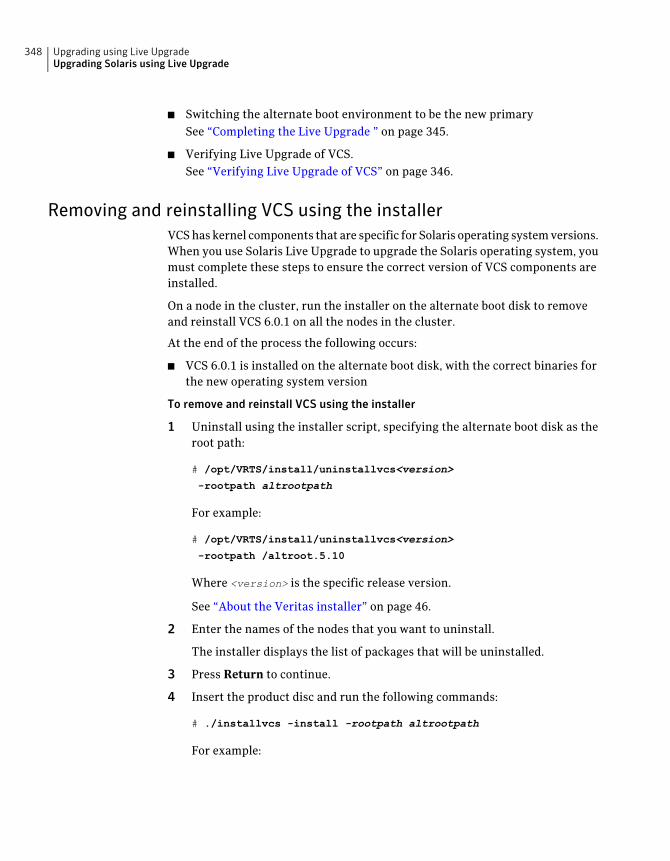
■ Switching the alternate boot environment to be the new primarySee “Completing the Live Upgrade ” on page 345.
■ Verifying Live Upgrade of VCS.See “Verifying Live Upgrade of VCS” on page 346.
Removing and reinstalling VCS using the installerVCS has kernel components that are specific for Solaris operating system versions.When you use Solaris Live Upgrade to upgrade the Solaris operating system, youmust complete these steps to ensure the correct version of VCS components areinstalled.
On a node in the cluster, run the installer on the alternate boot disk to removeand reinstall VCS 6.0.1 on all the nodes in the cluster.
At the end of the process the following occurs:
■ VCS 6.0.1 is installed on the alternate boot disk, with the correct binaries forthe new operating system version
To remove and reinstall VCS using the installer
1 Uninstall using the installer script, specifying the alternate boot disk as theroot path:
# /opt/VRTS/install/uninstallvcs<version>
-rootpath altrootpath
For example:
# /opt/VRTS/install/uninstallvcs<version>
-rootpath /altroot.5.10
Where <version> is the specific release version.
See “About the Veritas installer” on page 46.
2 Enter the names of the nodes that you want to uninstall.
The installer displays the list of packages that will be uninstalled.
3 Press Return to continue.
4 Insert the product disc and run the following commands:
# ./installvcs -install -rootpath altrootpath
For example:
Upgrading using Live UpgradeUpgrading Solaris using Live Upgrade
348
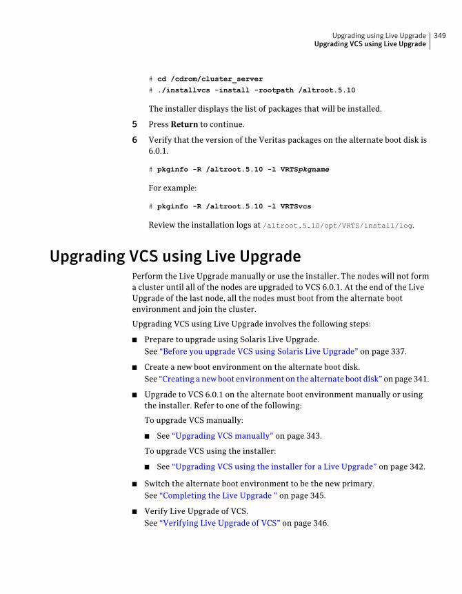
# cd /cdrom/cluster_server
# ./installvcs -install -rootpath /altroot.5.10
The installer displays the list of packages that will be installed.
5 Press Return to continue.
6 Verify that the version of the Veritas packages on the alternate boot disk is6.0.1.
# pkginfo -R /altroot.5.10 -l VRTSpkgname
For example:
# pkginfo -R /altroot.5.10 -l VRTSvcs
Review the installation logs at /altroot.5.10/opt/VRTS/install/log.
Upgrading VCS using Live UpgradePerform the Live Upgrade manually or use the installer. The nodes will not forma cluster until all of the nodes are upgraded to VCS 6.0.1. At the end of the LiveUpgrade of the last node, all the nodes must boot from the alternate bootenvironment and join the cluster.
Upgrading VCS using Live Upgrade involves the following steps:
■ Prepare to upgrade using Solaris Live Upgrade.See “Before you upgrade VCS using Solaris Live Upgrade” on page 337.
■ Create a new boot environment on the alternate boot disk.See “Creating a new boot environment on the alternate boot disk” on page 341.
■ Upgrade to VCS 6.0.1 on the alternate boot environment manually or usingthe installer. Refer to one of the following:
To upgrade VCS manually:
■ See “Upgrading VCS manually” on page 343.
To upgrade VCS using the installer:
■ See “Upgrading VCS using the installer for a Live Upgrade” on page 342.
■ Switch the alternate boot environment to be the new primary.See “Completing the Live Upgrade ” on page 345.
■ Verify Live Upgrade of VCS.See “Verifying Live Upgrade of VCS” on page 346.
349Upgrading using Live UpgradeUpgrading VCS using Live Upgrade
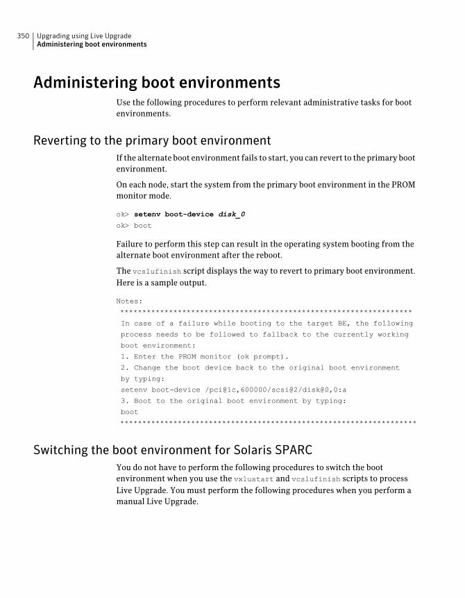
Administering boot environmentsUse the following procedures to perform relevant administrative tasks for bootenvironments.
Reverting to the primary boot environmentIf the alternate boot environment fails to start, you can revert to the primary bootenvironment.
On each node, start the system from the primary boot environment in the PROMmonitor mode.
ok> setenv boot-device disk_0
ok> boot
Failure to perform this step can result in the operating system booting from thealternate boot environment after the reboot.
The vcslufinish script displays the way to revert to primary boot environment.Here is a sample output.
Notes:
******************************************************************
In case of a failure while booting to the target BE, the following
process needs to be followed to fallback to the currently working
boot environment:
1. Enter the PROM monitor (ok prompt).
2. Change the boot device back to the original boot environment
by typing:
setenv boot-device /pci@1c,600000/scsi@2/disk@0,0:a
3. Boot to the original boot environment by typing:
boot
*******************************************************************
Switching the boot environment for Solaris SPARCYou do not have to perform the following procedures to switch the bootenvironment when you use the vxlustart and vcslufinish scripts to processLive Upgrade. You must perform the following procedures when you perform amanual Live Upgrade.
Upgrading using Live UpgradeAdministering boot environments
350

To switch the boot environment
1 Display the status of Live Upgrade boot environments.
# lustatus
Boot Environment Is Active Active Can Copy
Name Complete Now On Reboot Delete Status
---------------- -------- ------ --------- ------ ------
source.2657 yes yes yes no -
dest.2657 yes no no yes -
In this example, the primary boot disk is currently (source.2657). You wantto activate the alternate boot disk (dest.2657)
2 Unmount any file systems that are mounted on the alternate root disk(dest.2657).
# lufslist dest.2657
boot environment name: dest.2657
Filesystem fstype device size Mounted on Mount Options
----------------- ------ ------------ ---------- -------------
/dev/dsk/c0t0d0s1 swap 4298342400 - -
/dev/dsk/c0t0d0s0 ufs 15729328128 / -
/dev/dsk/c0t0d0s5 ufs 8591474688 /var -
/dev/dsk/c0t0d0s3 ufs 5371625472 /vxfs -
# luumount dest.2657
3 Activate the Live Upgrade boot environment.
# luactivate dest.2657
4 Reboot the system.
# shutdown -g0 -i6 -y
The system automatically selects the boot environment entry that wasactivated.
Switching the boot environment for Solaris x86-64You do not have to perform the following procedures to switch the bootenvironment when you use the vxlustart and vcslufinish scripts to process
351Upgrading using Live UpgradeAdministering boot environments
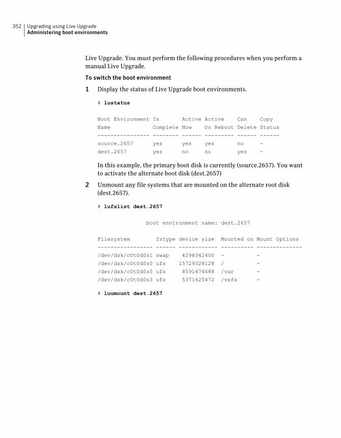
Live Upgrade. You must perform the following procedures when you perform amanual Live Upgrade.
To switch the boot environment
1 Display the status of Live Upgrade boot environments.
# lustatus
Boot Environment Is Active Active Can Copy
Name Complete Now On Reboot Delete Status
---------------- -------- ------ --------- ------ ------
source.2657 yes yes yes no -
dest.2657 yes no no yes -
In this example, the primary boot disk is currently (source.2657). You wantto activate the alternate boot disk (dest.2657)
2 Unmount any file systems that are mounted on the alternate root disk(dest.2657).
# lufslist dest.2657
boot environment name: dest.2657
Filesystem fstype device size Mounted on Mount Options
----------------- ------ ------------ ---------- --------------
/dev/dsk/c0t0d0s1 swap 4298342400 - -
/dev/dsk/c0t0d0s0 ufs 15729328128 / -
/dev/dsk/c0t0d0s5 ufs 8591474688 /var -
/dev/dsk/c0t0d0s3 ufs 5371625472 /vxfs -
# luumount dest.2657
Upgrading using Live UpgradeAdministering boot environments
352

3 Activate the Live Upgrade boot environment.
# luactivate dest.2657
4 Reboot the system.
# shutdown -g0 -i6 -y
When the system boots up, the GRUB menu displays the following entriesfor the Live Upgrade boot environments:
source.2657
dest.2657
The system automatically selects the boot environment entry that wasactivated.
353Upgrading using Live UpgradeAdministering boot environments

Upgrading using Live UpgradeAdministering boot environments
354
Post-installation tasks
■ Chapter 25. Performing post-installation tasks
■ Chapter 26. Installing or upgrading VCS components
■ Chapter 27. Verifying the VCS installation
8Section

356
Performingpost-installation tasks
This chapter includes the following topics:
■ About enabling LDAP authentication for clusters that run in secure mode
■ Accessing the VCS documentation
■ Removing permissions for communication
■ Changing root user into root role
About enabling LDAP authentication for clusters thatrun in secure mode
Symantec Product Authentication Service (AT) supports LDAP (LightweightDirectory Access Protocol) user authentication through a plug-in for theauthentication broker. AT supports all common LDAP distributions such asOpenLDAP and Windows Active Directory.
For a cluster that runs in secure mode, you must enable the LDAP authenticationplug-in if the VCS users belong to an LDAP domain.
If you have not already added VCS users during installation, you can add the userslater.
See the Veritas Cluster Server Administrator's Guide for instructions to add VCSusers.
Figure 25-1 depicts the VCS cluster communication with the LDAP servers whenclusters run in secure mode.
25Chapter
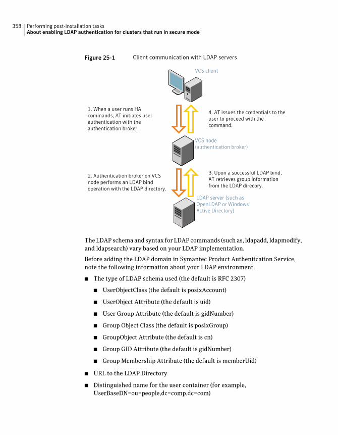
Figure 25-1 Client communication with LDAP servers
VCS node(authentication broker)
VCS client
1. When a user runs HAcommands, AT initiates userauthentication with theauthentication broker.
4. AT issues the credentials to theuser to proceed with thecommand.
2. Authentication broker on VCSnode performs an LDAP bindoperation with the LDAP directory.
3. Upon a successful LDAP bind,AT retrieves group informationfrom the LDAP direcory.
LDAP server (such asOpenLDAP or WindowsActive Directory)
The LDAP schema and syntax for LDAP commands (such as, ldapadd, ldapmodify,and ldapsearch) vary based on your LDAP implementation.
Before adding the LDAP domain in Symantec Product Authentication Service,note the following information about your LDAP environment:
■ The type of LDAP schema used (the default is RFC 2307)
■ UserObjectClass (the default is posixAccount)
■ UserObject Attribute (the default is uid)
■ User Group Attribute (the default is gidNumber)
■ Group Object Class (the default is posixGroup)
■ GroupObject Attribute (the default is cn)
■ Group GID Attribute (the default is gidNumber)
■ Group Membership Attribute (the default is memberUid)
■ URL to the LDAP Directory
■ Distinguished name for the user container (for example,UserBaseDN=ou=people,dc=comp,dc=com)
Performing post-installation tasksAbout enabling LDAP authentication for clusters that run in secure mode
358
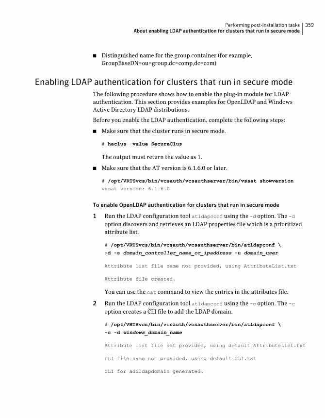
■ Distinguished name for the group container (for example,GroupBaseDN=ou=group,dc=comp,dc=com)
Enabling LDAP authentication for clusters that run in secure modeThe following procedure shows how to enable the plug-in module for LDAPauthentication. This section provides examples for OpenLDAP and WindowsActive Directory LDAP distributions.
Before you enable the LDAP authentication, complete the following steps:
■ Make sure that the cluster runs in secure mode.
# haclus -value SecureClus
The output must return the value as 1.
■ Make sure that the AT version is 6.1.6.0 or later.
# /opt/VRTSvcs/bin/vcsauth/vcsauthserver/bin/vssat showversion
vssat version: 6.1.6.0
To enable OpenLDAP authentication for clusters that run in secure mode
1 Run the LDAP configuration tool atldapconf using the -d option. The -d
option discovers and retrieves an LDAP properties file which is a prioritizedattribute list.
# /opt/VRTSvcs/bin/vcsauth/vcsauthserver/bin/atldapconf \
-d -s domain_controller_name_or_ipaddress -u domain_user
Attribute list file name not provided, using AttributeList.txt
Attribute file created.
You can use the cat command to view the entries in the attributes file.
2 Run the LDAP configuration tool atldapconf using the -c option. The -c
option creates a CLI file to add the LDAP domain.
# /opt/VRTSvcs/bin/vcsauth/vcsauthserver/bin/atldapconf \
-c -d windows_domain_name
Attribute list file not provided, using default AttributeList.txt
CLI file name not provided, using default CLI.txt
CLI for addldapdomain generated.
359Performing post-installation tasksAbout enabling LDAP authentication for clusters that run in secure mode
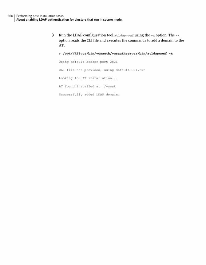
3 Run the LDAP configuration tool atldapconf using the -x option. The -x
option reads the CLI file and executes the commands to add a domain to theAT.
# /opt/VRTSvcs/bin/vcsauth/vcsauthserver/bin/atldapconf -x
Using default broker port 2821
CLI file not provided, using default CLI.txt
Looking for AT installation...
AT found installed at ./vssat
Successfully added LDAP domain.
Performing post-installation tasksAbout enabling LDAP authentication for clusters that run in secure mode
360
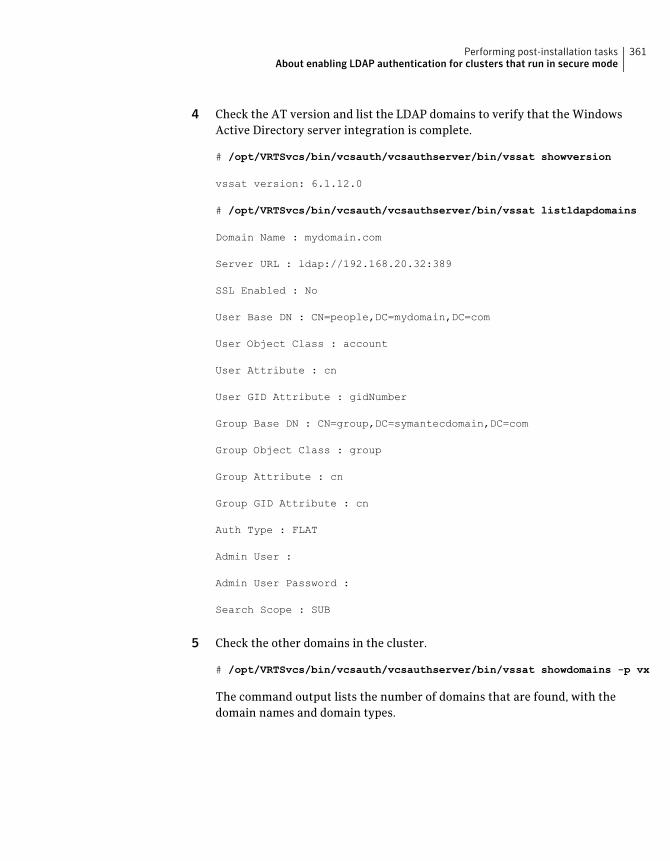
4 Check the AT version and list the LDAP domains to verify that the WindowsActive Directory server integration is complete.
# /opt/VRTSvcs/bin/vcsauth/vcsauthserver/bin/vssat showversion
vssat version: 6.1.12.0
# /opt/VRTSvcs/bin/vcsauth/vcsauthserver/bin/vssat listldapdomains
Domain Name : mydomain.com
Server URL : ldap://192.168.20.32:389
SSL Enabled : No
User Base DN : CN=people,DC=mydomain,DC=com
User Object Class : account
User Attribute : cn
User GID Attribute : gidNumber
Group Base DN : CN=group,DC=symantecdomain,DC=com
Group Object Class : group
Group Attribute : cn
Group GID Attribute : cn
Auth Type : FLAT
Admin User :
Admin User Password :
Search Scope : SUB
5 Check the other domains in the cluster.
# /opt/VRTSvcs/bin/vcsauth/vcsauthserver/bin/vssat showdomains -p vx
The command output lists the number of domains that are found, with thedomain names and domain types.
361Performing post-installation tasksAbout enabling LDAP authentication for clusters that run in secure mode

6 Generate credentials for the user.
# unset EAT_LOG
# /opt/VRTSvcs/bin/vcsauth/vcsauthserver/bin/vssat authenticate \
-d ldap:windows_domain_name -p user_name -s user_password -b \
localhost:14149
Performing post-installation tasksAbout enabling LDAP authentication for clusters that run in secure mode
362
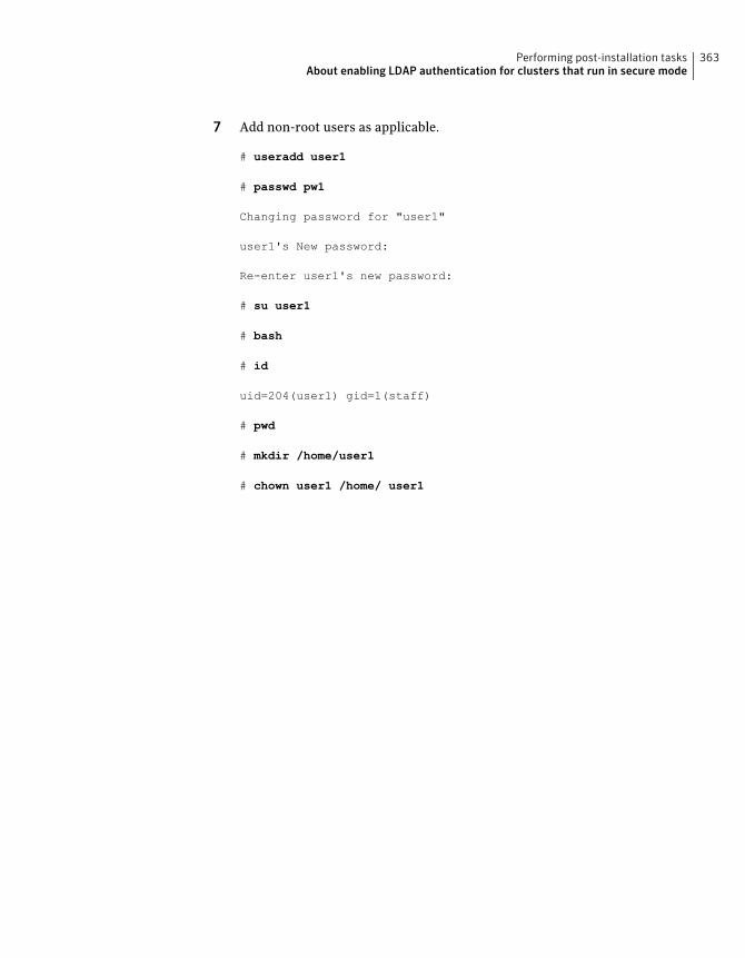
7 Add non-root users as applicable.
# useradd user1
# passwd pw1
Changing password for "user1"
user1's New password:
Re-enter user1's new password:
# su user1
# bash
# id
uid=204(user1) gid=1(staff)
# pwd
# mkdir /home/user1
# chown user1 /home/ user1
363Performing post-installation tasksAbout enabling LDAP authentication for clusters that run in secure mode
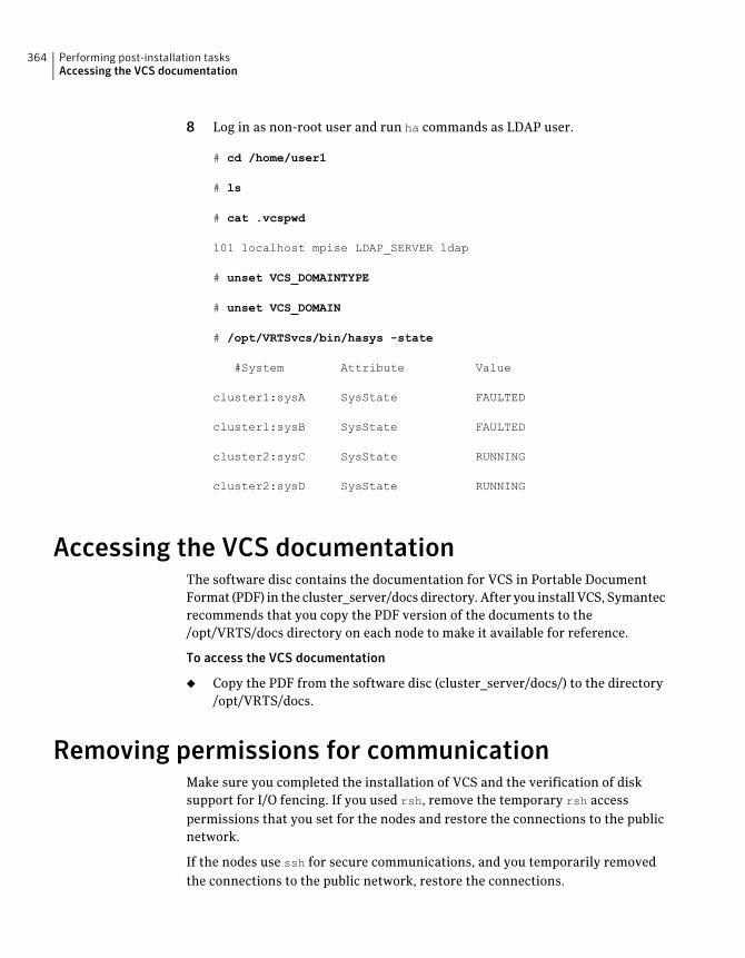
8 Log in as non-root user and run ha commands as LDAP user.
# cd /home/user1
# ls
# cat .vcspwd
101 localhost mpise LDAP_SERVER ldap
# unset VCS_DOMAINTYPE
# unset VCS_DOMAIN
# /opt/VRTSvcs/bin/hasys -state
#System Attribute Value
cluster1:sysA SysState FAULTED
cluster1:sysB SysState FAULTED
cluster2:sysC SysState RUNNING
cluster2:sysD SysState RUNNING
Accessing the VCS documentationThe software disc contains the documentation for VCS in Portable DocumentFormat (PDF) in the cluster_server/docs directory. After you install VCS, Symantecrecommends that you copy the PDF version of the documents to the/opt/VRTS/docs directory on each node to make it available for reference.
To access the VCS documentation
◆ Copy the PDF from the software disc (cluster_server/docs/) to the directory/opt/VRTS/docs.
Removing permissions for communicationMake sure you completed the installation of VCS and the verification of disksupport for I/O fencing. If you used rsh, remove the temporary rsh accesspermissions that you set for the nodes and restore the connections to the publicnetwork.
If the nodes use ssh for secure communications, and you temporarily removedthe connections to the public network, restore the connections.
Performing post-installation tasksAccessing the VCS documentation
364
Changing root user into root roleOn Oracle Solaris 11, to perform installation, you need to create root user. Thismeans that a local user cannot assume the root role. After installation, you maywant to turn root user into root role for a local user, who can log in as root.
1. Log in as root user.
2. Change the root account into role.
# rolemod -K type=role root
# getent user_attr root
root::::type=role;auths=solaris.*;profiles=All;audit_flags=lo\
:no;lock_after_retries=no;min_label=admin_low;clearance=admin_high
3. Assign the root role to a local user who was unassigned the role.
# usermod -R root admin
For more information, see the Oracle documentation on Oracle Solaris 11 operatingsystem.
365Performing post-installation tasksChanging root user into root role

Performing post-installation tasksChanging root user into root role
366
Installing or upgrading VCScomponents
This chapter includes the following topics:
■ Installing the Java Console
■ Upgrading the Java Console
■ Installing VCS Simulator
■ Upgrading VCS Simulator
Installing the Java ConsoleYou can administer VCS using the VCS Java-based graphical user interface, JavaConsole. After VCS has been installed, install the Java Console on a Windowssystem or Solaris system with X-Windows. Review the software requirements forJava Console.
The system from which you run the Java Console can be a system in the clusteror a remote workstation. A remote workstation enables each system in the clusterto be administered remotely.
When you install the Java Console on the Solaris system, make sure a printer isconfigured to that system. If you print the online JavaHelp on a system that doesnot have a printer that is configured, the Java Console might hang.
Review the information about using the Java Console. For more information, referto the Veritas Cluster Server Administrator's Guide.
Software requirements for the Java ConsoleCluster Manager (Java Console) is supported on:
26Chapter
■ Solaris SPARC 2.10
■ Windows XP and Windows 2003
Note: Make sure that you are using an operating system version that supportsJRE 1.6.
Hardware requirements for the Java ConsoleThe minimum hardware requirements for the Java Console follow:
■ Pentium II 300 megahertz
■ 256 megabytes of RAM
■ 800x600 display resolution
■ 8-bit color depth of the monitor
■ A graphics card that is capable of 2D images
Note: Symantec recommends using Pentium III 400MHz or higher, 256MB RAMor higher, and 800x600 display resolution or higher.
The version of the Java™ 2 Runtime Environment (JRE) requires 32 megabytes ofRAM.
Symantec recommends using the following hardware:
■ 48 megabytes of RAM
■ 16-bit color mode
■ The KDE and the KWM window managers that are used with displays set tolocal hosts
Installing the Java Console on SolarisReview the procedure to install the Java console. Before you begin with theprocedure, ensure that you have the gunzip utility installed on your system.
To install Java console on Solaris
1 Create a directory for installation of the Java Console:
# mkdir /tmp/install
Installing or upgrading VCS componentsInstalling the Java Console
368
2 Download the Java GUI utility from http://go.symantec.com/vcsm_downloadto a temporary directory.
3 Go to the temporary directory and unzip the compressed package file usingthe gunzip utility:
# cd /tmp/install
# gunzip VRTScscm.tar.gz
The file VRTScscm.tar is now present in the temporary directory.
4 Extract the compressed file from the tar file:
# tar -xvf VRTScscm.tar
5 Install the software:
# pkgadd -d . VRTScscm
6 Answer Yes if prompted.
Installing the Java Console on a Windows systemReview the procedure to install the Java console on a Windows system.
To install the Java Console on a Windows system
1 Download the Java GUI utility from http://go.symantec.com/vcsm_downloadto a temporary directory.
2 Extract the zipped file to a temporary folder.
3 From this extracted folder, double-click setup.exe.
4 The Veritas Cluster Manager Install Wizard guides you through theinstallation process.
Upgrading the Java ConsoleUse one of the following applicable procedures to upgrade Java Console.
369Installing or upgrading VCS componentsUpgrading the Java Console
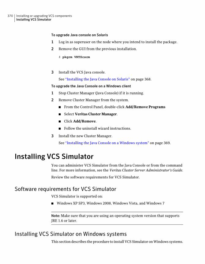
To upgrade Java console on Solaris
1 Log in as superuser on the node where you intend to install the package.
2 Remove the GUI from the previous installation.
# pkgrm VRTScscm
3 Install the VCS Java console.
See “Installing the Java Console on Solaris” on page 368.
To upgrade the Java Console on a Windows client
1 Stop Cluster Manager (Java Console) if it is running.
2 Remove Cluster Manager from the system.
■ From the Control Panel, double-click Add/Remove Programs
■ Select Veritas Cluster Manager.
■ Click Add/Remove.
■ Follow the uninstall wizard instructions.
3 Install the new Cluster Manager.
See “Installing the Java Console on a Windows system” on page 369.
Installing VCS SimulatorYou can administer VCS Simulator from the Java Console or from the commandline. For more information, see the Veritas Cluster Server Administrator's Guide.
Review the software requirements for VCS Simulator.
Software requirements for VCS SimulatorVCS Simulator is supported on:
■ Windows XP SP3, Windows 2008, Windows Vista, and Windows 7
Note: Make sure that you are using an operating system version that supportsJRE 1.6 or later.
Installing VCS Simulator on Windows systemsThis section describes the procedure to install VCS Simulator on Windows systems.
Installing or upgrading VCS componentsInstalling VCS Simulator
370
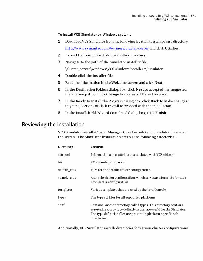
To install VCS Simulator on Windows systems
1 Download VCS Simulator from the following location to a temporary directory.
http://www.symantec.com/business/cluster-server and click Utilities.
2 Extract the compressed files to another directory.
3 Navigate to the path of the Simulator installer file:
\cluster_server\windows\VCSWindowsInstallers\Simulator
4 Double-click the installer file.
5 Read the information in the Welcome screen and click Next.
6 In the Destination Folders dialog box, click Next to accepted the suggestedinstallation path or click Change to choose a different location.
7 In the Ready to Install the Program dialog box, click Back to make changesto your selections or click Install to proceed with the installation.
8 In the Installshield Wizard Completed dialog box, click Finish.
Reviewing the installationVCS Simulator installs Cluster Manager (Java Console) and Simulator binaries onthe system. The Simulator installation creates the following directories:
ContentDirectory
Information about attributes associated with VCS objectsattrpool
VCS Simulator binariesbin
Files for the default cluster configurationdefault_clus
A sample cluster configuration, which serves as a template for eachnew cluster configuration
sample_clus
Various templates that are used by the Java Consoletemplates
The types.cf files for all supported platformstypes
Contains another directory called types. This directory containsassorted resource type definitions that are useful for the Simulator.The type definition files are present in platform-specific subdirectories.
conf
Additionally, VCS Simulator installs directories for various cluster configurations.
371Installing or upgrading VCS componentsInstalling VCS Simulator
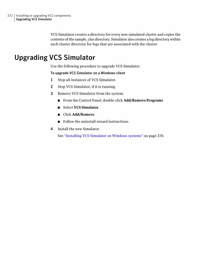
VCS Simulator creates a directory for every new simulated cluster and copies thecontents of the sample_clus directory. Simulator also creates a log directory withineach cluster directory for logs that are associated with the cluster.
Upgrading VCS SimulatorUse the following procedure to upgrade VCS Simulator.
To upgrade VCS Simulator on a Windows client
1 Stop all instances of VCS Simulator.
2 Stop VCS Simulator, if it is running.
3 Remove VCS Simulator from the system.
■ From the Control Panel, double-click Add/Remove Programs
■ Select VCS Simulator.
■ Click Add/Remove.
■ Follow the uninstall wizard instructions.
4 Install the new Simulator.
See “Installing VCS Simulator on Windows systems” on page 370.
Installing or upgrading VCS componentsUpgrading VCS Simulator
372
Verifying the VCSinstallation
This chapter includes the following topics:
■ About verifying the VCS installation
■ About the cluster UUID
■ Verifying the LLT, GAB, and VCS configuration files
■ Verifying LLT, GAB, and cluster operation
■ Performing a postcheck on a node
About verifying the VCS installationAfter you install and configure VCS, you can inspect the contents of the key VCSconfiguration files that you have installed and modified during the process. Thesefiles reflect the configuration that is based on the information you supplied. Youcan also run VCS commands to verify the status of LLT, GAB, and the cluster.
About the cluster UUIDYou can verify the existence of the cluster UUID.
To verify the cluster UUID exists
◆ From the prompt, run a cat command.
cat /etc/vx/.uuids/clusuuid
27Chapter
Verifying the LLT, GAB, and VCS configuration filesMake sure that the LLT, GAB, and VCS configuration files contain the informationyou provided during VCS installation and configuration.
To verify the LLT, GAB, and VCS configuration files
1 Navigate to the location of the configuration files:
■ LLT/etc/llthosts/etc/llttab
■ GAB/etc/gabtab
■ VCS/etc/VRTSvcs/conf/config/main.cf
2 Verify the content of the configuration files.
See “About the LLT and GAB configuration files” on page 485.
See “About the VCS configuration files” on page 489.
Verifying LLT, GAB, and cluster operationVerify the operation of LLT, GAB, and the cluster using the VCS commands.
To verify LLT, GAB, and cluster operation
1 Log in to any node in the cluster as superuser.
2 Make sure that the PATH environment variable is set to run the VCScommands.
See “Setting the PATH variable” on page 73.
3 Verify LLT operation.
See “Verifying LLT” on page 375.
4 Verify GAB operation.
See “Verifying GAB” on page 377.
5 Verify the cluster operation.
See “Verifying the cluster” on page 379.
Verifying the VCS installationVerifying the LLT, GAB, and VCS configuration files
374
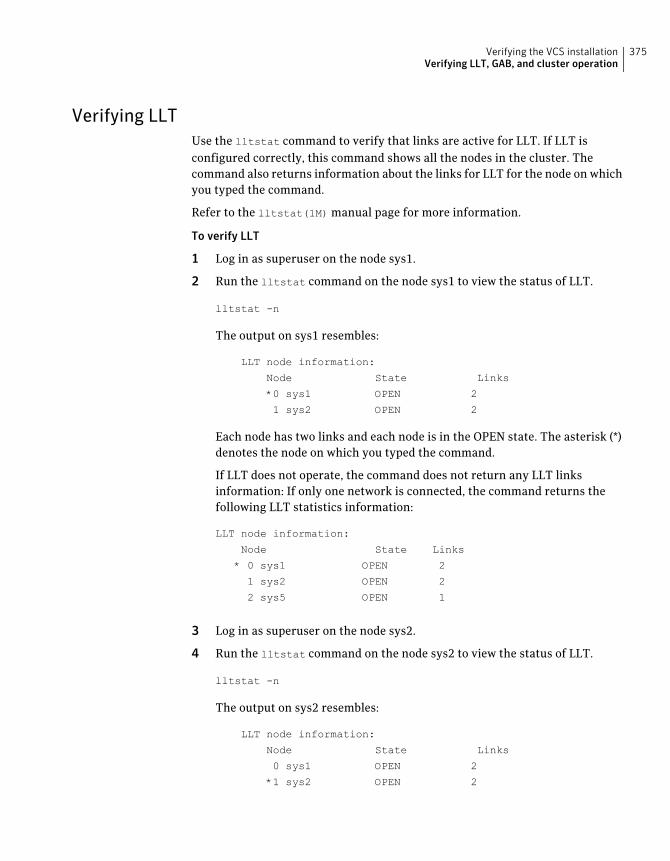
Verifying LLTUse the lltstat command to verify that links are active for LLT. If LLT isconfigured correctly, this command shows all the nodes in the cluster. Thecommand also returns information about the links for LLT for the node on whichyou typed the command.
Refer to the lltstat(1M) manual page for more information.
To verify LLT
1 Log in as superuser on the node sys1.
2 Run the lltstat command on the node sys1 to view the status of LLT.
lltstat -n
The output on sys1 resembles:
LLT node information:
Node State Links
*0 sys1 OPEN 2
1 sys2 OPEN 2
Each node has two links and each node is in the OPEN state. The asterisk (*)denotes the node on which you typed the command.
If LLT does not operate, the command does not return any LLT linksinformation: If only one network is connected, the command returns thefollowing LLT statistics information:
LLT node information:
Node State Links
* 0 sys1 OPEN 2
1 sys2 OPEN 2
2 sys5 OPEN 1
3 Log in as superuser on the node sys2.
4 Run the lltstat command on the node sys2 to view the status of LLT.
lltstat -n
The output on sys2 resembles:
LLT node information:
Node State Links
0 sys1 OPEN 2
*1 sys2 OPEN 2
375Verifying the VCS installationVerifying LLT, GAB, and cluster operation
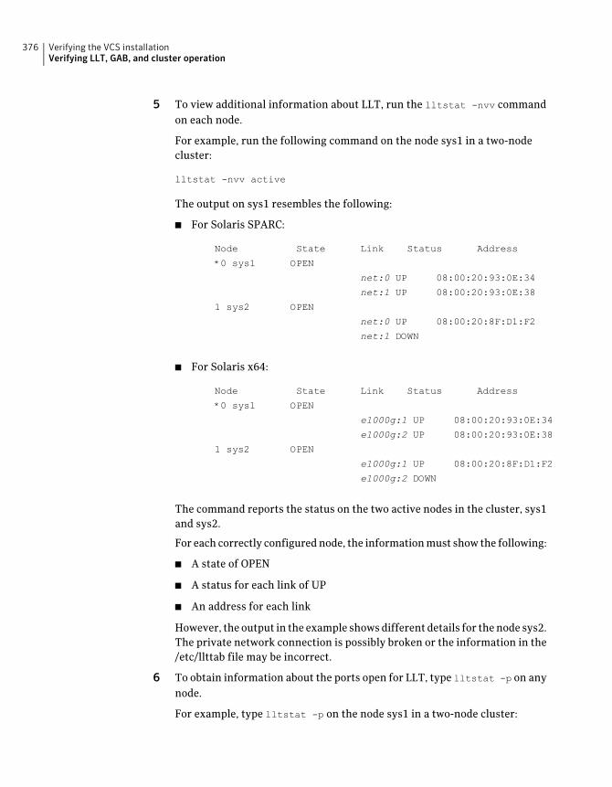
5 To view additional information about LLT, run the lltstat -nvv commandon each node.
For example, run the following command on the node sys1 in a two-nodecluster:
lltstat -nvv active
The output on sys1 resembles the following:
■ For Solaris SPARC:
Node State Link Status Address
*0 sys1 OPEN
net:0 UP 08:00:20:93:0E:34
net:1 UP 08:00:20:93:0E:38
1 sys2 OPEN
net:0 UP 08:00:20:8F:D1:F2
net:1 DOWN
■ For Solaris x64:
Node State Link Status Address
*0 sys1 OPEN
e1000g:1 UP 08:00:20:93:0E:34
e1000g:2 UP 08:00:20:93:0E:38
1 sys2 OPEN
e1000g:1 UP 08:00:20:8F:D1:F2
e1000g:2 DOWN
The command reports the status on the two active nodes in the cluster, sys1and sys2.
For each correctly configured node, the information must show the following:
■ A state of OPEN
■ A status for each link of UP
■ An address for each link
However, the output in the example shows different details for the node sys2.The private network connection is possibly broken or the information in the/etc/llttab file may be incorrect.
6 To obtain information about the ports open for LLT, type lltstat -p on anynode.
For example, type lltstat -p on the node sys1 in a two-node cluster:
Verifying the VCS installationVerifying LLT, GAB, and cluster operation
376
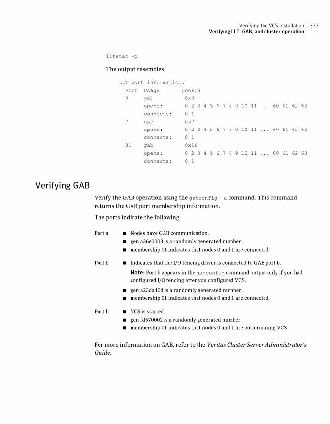
lltstat -p
The output resembles:
LLT port information:
Port Usage Cookie
0 gab 0x0
opens: 0 2 3 4 5 6 7 8 9 10 11 ... 60 61 62 63
connects: 0 1
7 gab 0x7
opens: 0 2 3 4 5 6 7 8 9 10 11 ... 60 61 62 63
connects: 0 1
31 gab 0x1F
opens: 0 2 3 4 5 6 7 8 9 10 11 ... 60 61 62 63
connects: 0 1
Verifying GABVerify the GAB operation using the gabconfig -a command. This commandreturns the GAB port membership information.
The ports indicate the following:
■ Nodes have GAB communication.
■ gen a36e0003 is a randomly generated number.
■ membership 01 indicates that nodes 0 and 1 are connected.
Port a
■ Indicates that the I/O fencing driver is connected to GAB port b.
Note: Port b appears in the gabconfig command output only if you hadconfigured I/O fencing after you configured VCS.
■ gen a23da40d is a randomly generated number.
■ membership 01 indicates that nodes 0 and 1 are connected.
Port b
■ VCS is started.
■ gen fd570002 is a randomly generated number
■ membership 01 indicates that nodes 0 and 1 are both running VCS
Port h
For more information on GAB, refer to theVeritas Cluster Server Administrator'sGuide.
377Verifying the VCS installationVerifying LLT, GAB, and cluster operation
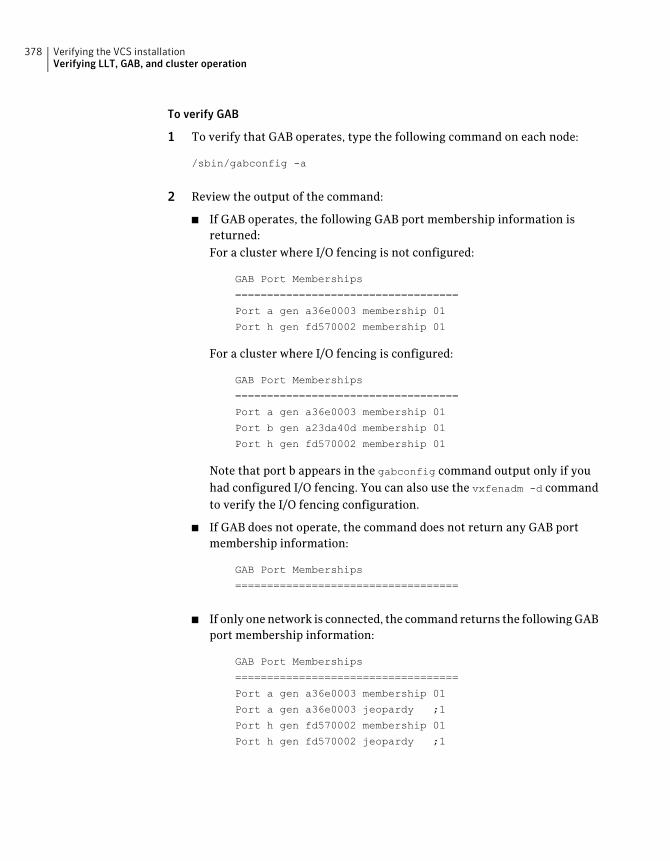
To verify GAB
1 To verify that GAB operates, type the following command on each node:
/sbin/gabconfig -a
2 Review the output of the command:
■ If GAB operates, the following GAB port membership information isreturned:For a cluster where I/O fencing is not configured:
GAB Port Memberships
===================================
Port a gen a36e0003 membership 01
Port h gen fd570002 membership 01
For a cluster where I/O fencing is configured:
GAB Port Memberships
===================================
Port a gen a36e0003 membership 01
Port b gen a23da40d membership 01
Port h gen fd570002 membership 01
Note that port b appears in the gabconfig command output only if youhad configured I/O fencing. You can also use the vxfenadm -d commandto verify the I/O fencing configuration.
■ If GAB does not operate, the command does not return any GAB portmembership information:
GAB Port Memberships
===================================
■ If only one network is connected, the command returns the following GABport membership information:
GAB Port Memberships
===================================
Port a gen a36e0003 membership 01
Port a gen a36e0003 jeopardy ;1
Port h gen fd570002 membership 01
Port h gen fd570002 jeopardy ;1
Verifying the VCS installationVerifying LLT, GAB, and cluster operation
378
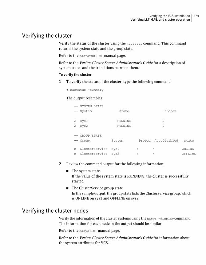
Verifying the clusterVerify the status of the cluster using the hastatus command. This commandreturns the system state and the group state.
Refer to the hastatus(1M) manual page.
Refer to the Veritas Cluster Server Administrator's Guide for a description ofsystem states and the transitions between them.
To verify the cluster
1 To verify the status of the cluster, type the following command:
# hastatus -summary
The output resembles:
-- SYSTEM STATE
-- System State Frozen
A sys1 RUNNING 0
A sys2 RUNNING 0
-- GROUP STATE
-- Group System Probed AutoDisabled State
B ClusterService sys1 Y N ONLINE
B ClusterService sys2 Y N OFFLINE
2 Review the command output for the following information:
■ The system stateIf the value of the system state is RUNNING, the cluster is successfullystarted.
■ The ClusterService group stateIn the sample output, the group state lists the ClusterService group, whichis ONLINE on sys1 and OFFLINE on sys2.
Verifying the cluster nodesVerify the information of the cluster systems using thehasys -display command.The information for each node in the output should be similar.
Refer to the hasys(1M) manual page.
Refer to the Veritas Cluster Server Administrator's Guide for information aboutthe system attributes for VCS.
379Verifying the VCS installationVerifying LLT, GAB, and cluster operation
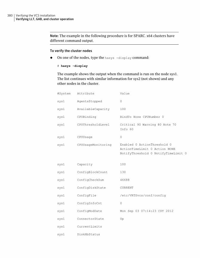
Note: The example in the following procedure is for SPARC. x64 clusters havedifferent command output.
To verify the cluster nodes
◆ On one of the nodes, type the hasys -display command:
# hasys -display
The example shows the output when the command is run on the node sys1.The list continues with similar information for sys2 (not shown) and anyother nodes in the cluster.
ValueAttribute#System
0AgentsStoppedsys1
100AvailableCapacitysys1
BindTo None CPUNumber 0CPUBindingsys1
Critical 90 Warning 80 Note 70
Info 60
CPUThresholdLevelsys1
0CPUUsagesys1
Enabled 0 ActionThreshold 0ActionTimeLimit 0 Action NONENotifyThreshold 0 NotifyTimeLimit 0
CPUUsageMonitoringsys1
100Capacitysys1
130ConfigBlockCountsys1
46688ConfigCheckSumsys1
CURRENTConfigDiskStatesys1
/etc/VRTSvcs/conf/configConfigFilesys1
0ConfigInfoCntsys1
Mon Sep 03 07:14:23 CDT 2012ConfigModDatesys1
UpConnectorStatesys1
CurrentLimitssys1
DiskHbStatussys1
Verifying the VCS installationVerifying LLT, GAB, and cluster operation
380
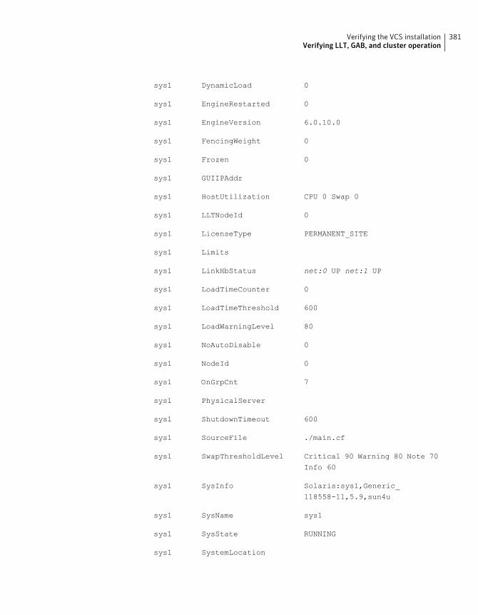
0DynamicLoadsys1
0EngineRestartedsys1
6.0.10.0EngineVersionsys1
0FencingWeightsys1
0Frozensys1
GUIIPAddrsys1
CPU 0 Swap 0HostUtilizationsys1
0LLTNodeIdsys1
PERMANENT_SITELicenseTypesys1
Limitssys1
net:0 UP net:1 UPLinkHbStatussys1
0LoadTimeCountersys1
600LoadTimeThresholdsys1
80LoadWarningLevelsys1
0NoAutoDisablesys1
0NodeIdsys1
7OnGrpCntsys1
PhysicalServersys1
600ShutdownTimeoutsys1
./main.cfSourceFilesys1
Critical 90 Warning 80 Note 70
Info 60
SwapThresholdLevelsys1
Solaris:sys1,Generic_
118558-11,5.9,sun4u
SysInfosys1
sys1SysNamesys1
RUNNINGSysStatesys1
SystemLocationsys1
381Verifying the VCS installationVerifying LLT, GAB, and cluster operation
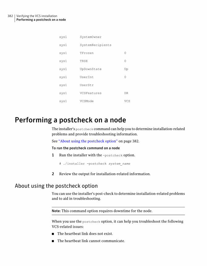
SystemOwnersys1
SystemRecipientssys1
0TFrozensys1
0TRSEsys1
UpUpDownStatesys1
0UserIntsys1
UserStrsys1
DRVCSFeaturessys1
VCSVCSModesys1
Performing a postcheck on a nodeThe installer's postcheck command can help you to determine installation-relatedproblems and provide troubleshooting information.
See “About using the postcheck option” on page 382.
To run the postcheck command on a node
1 Run the installer with the -postcheck option.
# ./installer -postcheck system_name
2 Review the output for installation-related information.
About using the postcheck optionYou can use the installer's post-check to determine installation-related problemsand to aid in troubleshooting.
Note: This command option requires downtime for the node.
When you use the postcheck option, it can help you troubleshoot the followingVCS-related issues:
■ The heartbeat link does not exist.
■ The heartbeat link cannot communicate.
Verifying the VCS installationPerforming a postcheck on a node
382
■ The heartbeat link is a part of a bonded or aggregated NIC.
■ A duplicated cluster ID exists (if LLT is not running at the check time).
■ The VRTSllt pkg version is not consistent on the nodes.
■ The llt-linkinstall value is incorrect.
■ The llthosts(4) or llttab(4) configuration is incorrect.
■ the /etc/gabtab file is incorrect.
■ The incorrect GAB linkinstall value exists.
■ The VRTSgab pkg version is not consistent on the nodes.
■ The main.cf file or the types.cf file is invalid.
■ The /etc/VRTSvcs/conf/sysname file is not consistent with the hostname.
■ The cluster UUID does not exist.
■ The uuidconfig.pl file is missing.
■ The VRTSvcs pkg version is not consistent on the nodes.
■ The /etc/vxfenmode file is missing or incorrect.
■ The /etc/vxfendg file is invalid.
■ The vxfen link-install value is incorrect.
■ The VRTSvxfen pkg version is not consistent.
The postcheck option can help you troubleshoot the following SFHA or SFCFSHAissues:
■ Volume Manager cannot start because the/etc/vx/reconfig.d/state.d/install-db file has not been removed.
■ Volume Manager cannot start because the volboot file is not loaded.
■ Volume Manager cannot start because no license exists.
■ Cluster Volume Manager cannot start because the CVM configuration isincorrect in the main.cf file. For example, the Autostartlist value is missingon the nodes.
■ Cluster Volume Manager cannot come online because the node ID in the/etc/llthosts file is not consistent.
■ Cluster Volume Manager cannot come online because Vxfen is not started.
■ Cluster Volume Manager cannot start because gab is not configured.
383Verifying the VCS installationPerforming a postcheck on a node
■ Cluster Volume Manager cannot come online because of a CVM protocolmismatch.
■ Cluster Volume Manager group name has changed from "cvm", which causesCVM to go offline.
You can use the installer’s post-check option to perform the following checks:
General checks for all products:
■ All the required packages are installed.
■ The versions of the required packages are correct.
■ There are no verification issues for the required packages.
Checks for Volume Manager (VM):
■ Lists the daemons which are not running (vxattachd,vxconfigbackupd,vxesd,vxrelocd ...).
■ Lists the disks which are not in 'online' or 'online shared' state (vxdisk list).
■ Lists the diskgroups which are not in 'enabled' state (vxdg list).
■ Lists the volumes which are not in 'enabled' state (vxprint -g <dgname>).
■ Lists the volumes which are in 'Unstartable' state (vxinfo -g <dgname>).
■ Lists the volumes which are not configured in (AIX) /etc/filesystems,(Linux/HP-UX)/etc/fstab, or (SunOS)/etc/vfstab.
Checks for File System (FS):
■ Lists the VxFS kernel modules which are not loaded (vxfs/fdd/vxportal.).
■ Whether all VxFS file systems present in (AIX)
/etc/filesystems,(Linux/HP-UX)/etc/fstab, or (SunOS)/etc/vfstab fileare mounted.
■ Whether all VxFS file systems present in (AIX)
/etc/filesystems,(Linux/HP-UX)/etc/fstab, or (SunOS)/etc/vfstab arein disk layout 6 or higher.
■ Whether all mounted VxFS file systems are in disk layout 6 or higher.
Checks for Cluster File System:
■ Whether FS and ODM are running at the latest protocol level.
■ Whether all mounted CFS file systems are managed by VCS.
■ Whether cvm service group is online.
See “Performing a postcheck on a node” on page 382.
Verifying the VCS installationPerforming a postcheck on a node
384
Adding and removing clusternodes
■ Chapter 28. Adding a node to a single-node cluster
■ Chapter 29. Adding a node to a multi-node VCS cluster
■ Chapter 30. Removing a node from a VCS cluster
9Section

386
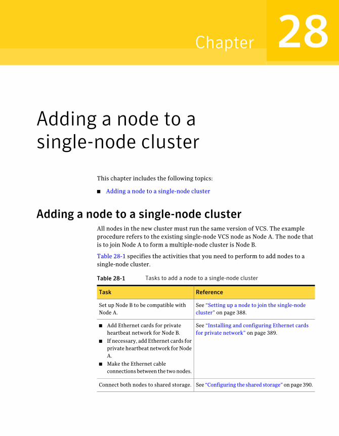
Adding a node to asingle-node cluster
This chapter includes the following topics:
■ Adding a node to a single-node cluster
Adding a node to a single-node clusterAll nodes in the new cluster must run the same version of VCS. The exampleprocedure refers to the existing single-node VCS node as Node A. The node thatis to join Node A to form a multiple-node cluster is Node B.
Table 28-1 specifies the activities that you need to perform to add nodes to asingle-node cluster.
Table 28-1 Tasks to add a node to a single-node cluster
ReferenceTask
See “Setting up a node to join the single-nodecluster” on page 388.
Set up Node B to be compatible withNode A.
See “Installing and configuring Ethernet cardsfor private network” on page 389.
■ Add Ethernet cards for privateheartbeat network for Node B.
■ If necessary, add Ethernet cards forprivate heartbeat network for NodeA.
■ Make the Ethernet cableconnections between the two nodes.
See “Configuring the shared storage” on page 390.Connect both nodes to shared storage.
28Chapter
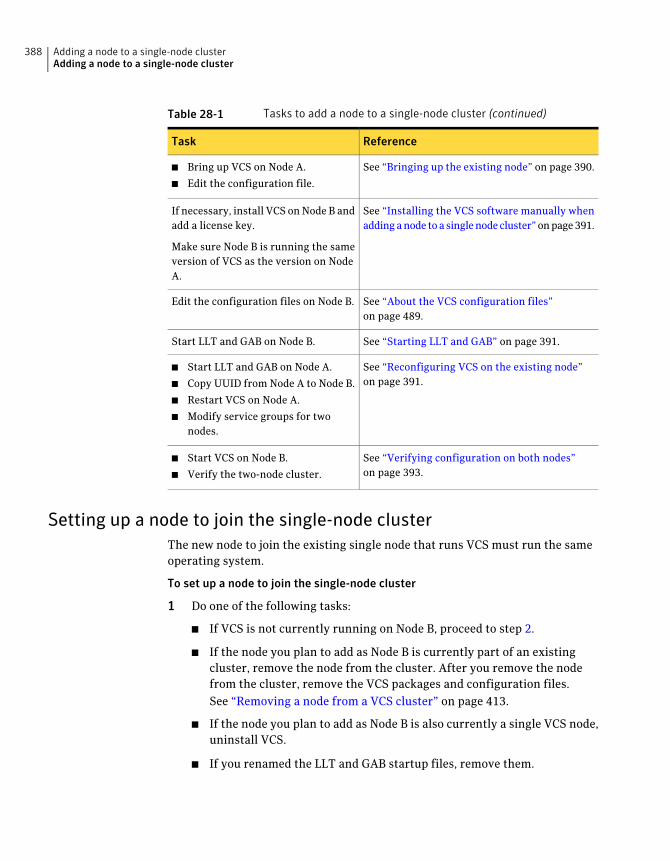
Table 28-1 Tasks to add a node to a single-node cluster (continued)
ReferenceTask
See “Bringing up the existing node” on page 390.■ Bring up VCS on Node A.
■ Edit the configuration file.
See “Installing the VCS software manually whenadding a node to a single node cluster” on page 391.
If necessary, install VCS on Node B andadd a license key.
Make sure Node B is running the sameversion of VCS as the version on NodeA.
See “About the VCS configuration files”on page 489.
Edit the configuration files on Node B.
See “Starting LLT and GAB” on page 391.Start LLT and GAB on Node B.
See “Reconfiguring VCS on the existing node”on page 391.
■ Start LLT and GAB on Node A.
■ Copy UUID from Node A to Node B.
■ Restart VCS on Node A.
■ Modify service groups for twonodes.
See “Verifying configuration on both nodes”on page 393.
■ Start VCS on Node B.
■ Verify the two-node cluster.
Setting up a node to join the single-node clusterThe new node to join the existing single node that runs VCS must run the sameoperating system.
To set up a node to join the single-node cluster
1 Do one of the following tasks:
■ If VCS is not currently running on Node B, proceed to step 2.
■ If the node you plan to add as Node B is currently part of an existingcluster, remove the node from the cluster. After you remove the nodefrom the cluster, remove the VCS packages and configuration files.See “Removing a node from a VCS cluster” on page 413.
■ If the node you plan to add as Node B is also currently a single VCS node,uninstall VCS.
■ If you renamed the LLT and GAB startup files, remove them.
Adding a node to a single-node clusterAdding a node to a single-node cluster
388
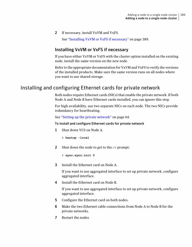
2 If necessary, install VxVM and VxFS.
See “Installing VxVM or VxFS if necessary” on page 389.
Installing VxVM or VxFS if necessaryIf you have either VxVM or VxFS with the cluster option installed on the existingnode, install the same version on the new node.
Refer to the appropriate documentation for VxVM and VxFS to verify the versionsof the installed products. Make sure the same version runs on all nodes whereyou want to use shared storage.
Installing and configuring Ethernet cards for private networkBoth nodes require Ethernet cards (NICs) that enable the private network. If bothNode A and Node B have Ethernet cards installed, you can ignore this step.
For high availability, use two separate NICs on each node. The two NICs provideredundancy for heartbeating.
See “Setting up the private network” on page 64.
To install and configure Ethernet cards for private network
1 Shut down VCS on Node A.
# hastop -local
2 Shut down the node to get to the OK prompt:
# sync;sync;init 0
3 Install the Ethernet card on Node A.
If you want to use aggregated interface to set up private network, configureaggregated interface.
4 Install the Ethernet card on Node B.
If you want to use aggregated interface to set up private network, configureaggregated interface.
5 Configure the Ethernet card on both nodes.
6 Make the two Ethernet cable connections from Node A to Node B for theprivate networks.
7 Restart the nodes.
389Adding a node to a single-node clusterAdding a node to a single-node cluster
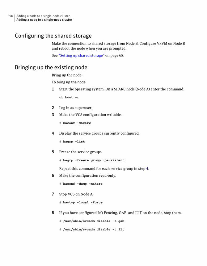
Configuring the shared storageMake the connection to shared storage from Node B. Configure VxVM on Node Band reboot the node when you are prompted.
See “Setting up shared storage” on page 68.
Bringing up the existing nodeBring up the node.
To bring up the node
1 Start the operating system. On a SPARC node (Node A) enter the command:
ok boot -r
2 Log in as superuser.
3 Make the VCS configuration writable.
# haconf -makerw
4 Display the service groups currently configured.
# hagrp -list
5 Freeze the service groups.
# hagrp -freeze group -persistent
Repeat this command for each service group in step 4.
6 Make the configuration read-only.
# haconf -dump -makero
7 Stop VCS on Node A.
# hastop -local -force
8 If you have configured I/O Fencing, GAB, and LLT on the node, stop them.
# /usr/sbin/svcadm disable -t gab
# /usr/sbin/svcadm disable -t llt
Adding a node to a single-node clusterAdding a node to a single-node cluster
390
Installing the VCS software manually when adding a node to a singlenode cluster
Install the VCS 6.0.1 packages manually and install the license key.
Refer to the following sections:
■ See “ Preparing for a manual installation” on page 227.
■ See “Adding a license key for a manual installation” on page 236.
Creating configuration filesCreate the configuration files for your cluster.
To create the configuration files
1 Create the file /etc/llttab for a two-node cluster
See “Setting up /etc/llttab for a manual installation” on page 254.
2 Create the file /etc/llthosts that list both the nodes.
See “Setting up /etc/llthosts for a manual installation” on page 254.
3 Create the file /etc/gabtab.
See “Configuring GAB manually” on page 257.
Starting LLT and GABOn the new node, start LLT and GAB.
To start LLT and GAB
1 Start LLT on Node B.
# /usr/sbin/svcadm enable llt
2 Start GAB on Node B
# /usr/sbin/svcadm enable gab
Reconfiguring VCS on the existing nodeReconfigure VCS on the existing nodes.
391Adding a node to a single-node clusterAdding a node to a single-node cluster
To reconfigure VCS on existing nodes
1 On Node A, create the files /etc/llttab, /etc/llthosts, and /etc/gabtab. Use thefiles that are created on Node B as a guide, customizing the /etc/llttab forNode A.
2 Start LLT on Node A.
# /usr/sbin/svcadm enable llt
3 Start GAB on Node A.
# /usr/sbin/svcadm enable gab
4 Check the membership of the cluster.
# gabconfig -a
5 Copy the cluster UUID from the existing node to the new node:
# /opt/VRTSvcs/bin/uuidconfig.pl -clus -copy -from_sys \
node_name_in_running_cluster -to_sys new_sys1 ... new_sysn
Where you are copying the cluster UUID from a node in the cluster(node_name_in_running_cluster) to systems fromnew_sys1 throughnew_sysnthat you want to join the cluster.
6 Delete the VCS one-node SMF configuration from SMF respository.
# svccfg -f delete vcs-onenode
7 Import the VCS SMF configuration to SMF respository.
# svccfg import /etc/VRTSvcs/conf/vcs.xml
Note: To start VCS using SMF service, use the svcadm enable vcs command.
8 Start VCS on Node A.
# hastart
9 Make the VCS configuration writable.
# haconf -makerw
Adding a node to a single-node clusterAdding a node to a single-node cluster
392
10 Add Node B to the cluster.
# hasys -add sysB
11 Add Node B to the system list of each service group.
■ List the service groups.
# hagrp -list
■ For each service group that is listed, add the node.
# hagrp -modify group SystemList -add sysB 1
Verifying configuration on both nodesVerify the configuration for the nodes.
To verify the nodes' configuration
1 On Node B, check the cluster membership.
# gabconfig -a
2 Start the VCS on Node B.
# hastart
3 Verify that VCS is up on both nodes.
# hastatus
4 List the service groups.
# hagrp -list
5 Unfreeze the service groups.
# hagrp -unfreeze group -persistent
6 Implement the new two-node configuration.
# haconf -dump -makero
393Adding a node to a single-node clusterAdding a node to a single-node cluster

Adding a node to a single-node clusterAdding a node to a single-node cluster
394
Adding a node to amulti-node VCS cluster
This chapter includes the following topics:
■ Adding nodes using the VCS installer
■ Adding a node using the Web-based installer
■ Manually adding a node to a cluster
Adding nodes using the VCS installerThe VCS installer performs the following tasks:
■ Verifies that the node and the existing cluster meet communicationrequirements.
■ Verifies the products and packages installed on the new node.
■ Discovers the network interfaces on the new node and checks the interfacesettings.
■ Creates the following files on the new node:/etc/llttab
/etc/VRTSvcs/conf/sysname
■ Updates the following configuration files and copies them on the new node:/etc/llthosts
/etc/gabtab
/etc/VRTSvcs/conf/config/main.cf
■ Copies the following files from the existing cluster to the new node/etc/vxfenmode
29Chapter
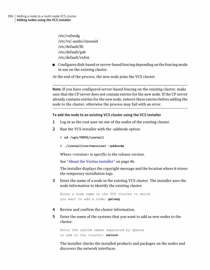
/etc/vxfendg/etc/vx/.uuids/clusuuid/etc/default/llt/etc/default/gab/etc/default/vxfen
■ Configures disk-based or server-based fencing depending on the fencing modein use on the existing cluster.
At the end of the process, the new node joins the VCS cluster.
Note: If you have configured server-based fencing on the existing cluster, makesure that the CP server does not contain entries for the new node. If the CP serveralready contains entries for the new node, remove these entries before adding thenode to the cluster, otherwise the process may fail with an error.
To add the node to an existing VCS cluster using the VCS installer
1 Log in as the root user on one of the nodes of the existing cluster.
2 Run the VCS installer with the -addnode option.
# cd /opt/VRTS/install
# ./installvcs<version> -addnode
Where <version> is specific to the release version.
See “About the Veritas installer” on page 46.
The installer displays the copyright message and the location where it storesthe temporary installation logs.
3 Enter the name of a node in the existing VCS cluster. The installer uses thenode information to identify the existing cluster.
Enter a node name in the VCS cluster to which
you want to add a node: galaxy
4 Review and confirm the cluster information.
5 Enter the name of the systems that you want to add as new nodes to thecluster.
Enter the system names separated by spaces
to add to the cluster: saturn
The installer checks the installed products and packages on the nodes anddiscovers the network interfaces.
Adding a node to a multi-node VCS clusterAdding nodes using the VCS installer
396
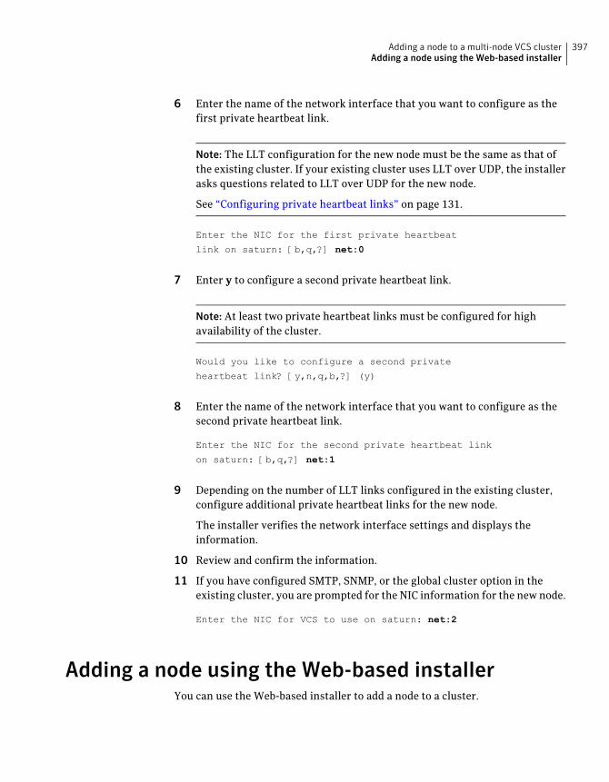
6 Enter the name of the network interface that you want to configure as thefirst private heartbeat link.
Note: The LLT configuration for the new node must be the same as that ofthe existing cluster. If your existing cluster uses LLT over UDP, the installerasks questions related to LLT over UDP for the new node.
See “Configuring private heartbeat links” on page 131.
Enter the NIC for the first private heartbeat
link on saturn: [b,q,?] net:0
7 Enter y to configure a second private heartbeat link.
Note: At least two private heartbeat links must be configured for highavailability of the cluster.
Would you like to configure a second private
heartbeat link? [y,n,q,b,?] (y)
8 Enter the name of the network interface that you want to configure as thesecond private heartbeat link.
Enter the NIC for the second private heartbeat link
on saturn: [b,q,?] net:1
9 Depending on the number of LLT links configured in the existing cluster,configure additional private heartbeat links for the new node.
The installer verifies the network interface settings and displays theinformation.
10 Review and confirm the information.
11 If you have configured SMTP, SNMP, or the global cluster option in theexisting cluster, you are prompted for the NIC information for the new node.
Enter the NIC for VCS to use on saturn: net:2
Adding a node using the Web-based installerYou can use the Web-based installer to add a node to a cluster.
397Adding a node to a multi-node VCS clusterAdding a node using the Web-based installer
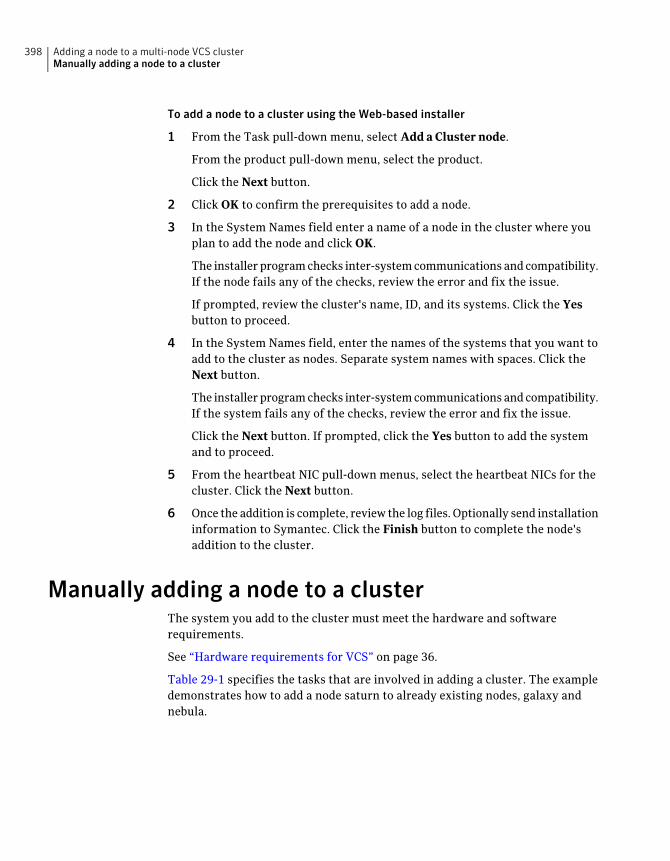
To add a node to a cluster using the Web-based installer
1 From the Task pull-down menu, select Add a Cluster node.
From the product pull-down menu, select the product.
Click the Next button.
2 Click OK to confirm the prerequisites to add a node.
3 In the System Names field enter a name of a node in the cluster where youplan to add the node and click OK.
The installer program checks inter-system communications and compatibility.If the node fails any of the checks, review the error and fix the issue.
If prompted, review the cluster's name, ID, and its systems. Click the Yesbutton to proceed.
4 In the System Names field, enter the names of the systems that you want toadd to the cluster as nodes. Separate system names with spaces. Click theNext button.
The installer program checks inter-system communications and compatibility.If the system fails any of the checks, review the error and fix the issue.
Click the Next button. If prompted, click the Yes button to add the systemand to proceed.
5 From the heartbeat NIC pull-down menus, select the heartbeat NICs for thecluster. Click the Next button.
6 Once the addition is complete, review the log files. Optionally send installationinformation to Symantec. Click the Finish button to complete the node'saddition to the cluster.
Manually adding a node to a clusterThe system you add to the cluster must meet the hardware and softwarerequirements.
See “Hardware requirements for VCS” on page 36.
Table 29-1 specifies the tasks that are involved in adding a cluster. The exampledemonstrates how to add a node saturn to already existing nodes, galaxy andnebula.
Adding a node to a multi-node VCS clusterManually adding a node to a cluster
398
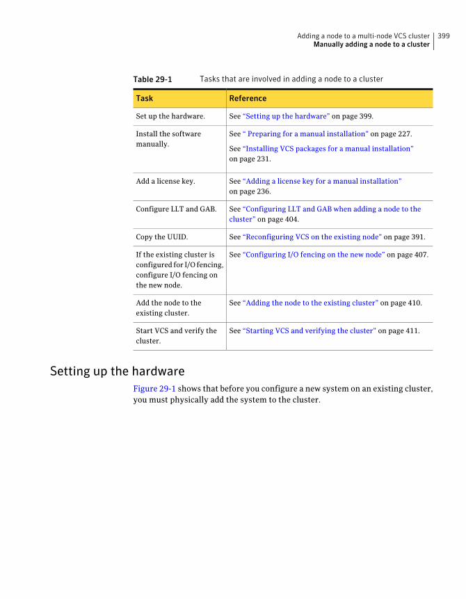
Table 29-1 Tasks that are involved in adding a node to a cluster
ReferenceTask
See “Setting up the hardware” on page 399.Set up the hardware.
See “ Preparing for a manual installation” on page 227.
See “Installing VCS packages for a manual installation”on page 231.
Install the softwaremanually.
See “Adding a license key for a manual installation”on page 236.
Add a license key.
See “Configuring LLT and GAB when adding a node to thecluster” on page 404.
Configure LLT and GAB.
See “Reconfiguring VCS on the existing node” on page 391.Copy the UUID.
See “Configuring I/O fencing on the new node” on page 407.If the existing cluster isconfigured for I/O fencing,configure I/O fencing onthe new node.
See “Adding the node to the existing cluster” on page 410.Add the node to theexisting cluster.
See “Starting VCS and verifying the cluster” on page 411.Start VCS and verify thecluster.
Setting up the hardwareFigure 29-1 shows that before you configure a new system on an existing cluster,you must physically add the system to the cluster.
399Adding a node to a multi-node VCS clusterManually adding a node to a cluster
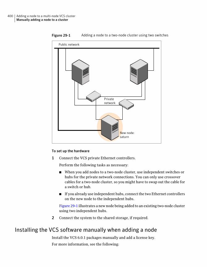
Figure 29-1 Adding a node to a two-node cluster using two switches
Public network
Privatenetwork
New node:saturn
To set up the hardware
1 Connect the VCS private Ethernet controllers.
Perform the following tasks as necessary:
■ When you add nodes to a two-node cluster, use independent switches orhubs for the private network connections. You can only use crossovercables for a two-node cluster, so you might have to swap out the cable fora switch or hub.
■ If you already use independent hubs, connect the two Ethernet controllerson the new node to the independent hubs.
Figure 29-1 illustrates a new node being added to an existing two-node clusterusing two independent hubs.
2 Connect the system to the shared storage, if required.
Installing the VCS software manually when adding a nodeInstall the VCS 6.0.1 packages manually and add a license key.
For more information, see the following:
Adding a node to a multi-node VCS clusterManually adding a node to a cluster
400
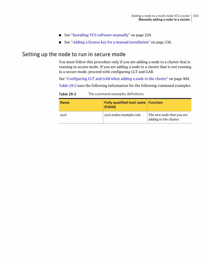
■ See “Installing VCS software manually” on page 229.
■ See “Adding a license key for a manual installation” on page 236.
Setting up the node to run in secure modeYou must follow this procedure only if you are adding a node to a cluster that isrunning in secure mode. If you are adding a node to a cluster that is not runningin a secure mode, proceed with configuring LLT and GAB.
See “Configuring LLT and GAB when adding a node to the cluster” on page 404.
Table 29-2 uses the following information for the following command examples.
Table 29-2 The command examples definitions
FunctionFully-qualified host name(FQHN)
Name
The new node that you areadding to the cluster.
sys5.nodes.example.comsys5
401Adding a node to a multi-node VCS clusterManually adding a node to a cluster
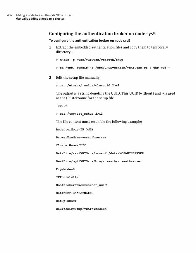
Configuring the authentication broker on node sys5To configure the authentication broker on node sys5
1 Extract the embedded authentication files and copy them to temporarydirectory:
# mkdir -p /var/VRTSvcs/vcsauth/bkup
# cd /tmp; gunzip -c /opt/VRTSvcs/bin/VxAT.tar.gz | tar xvf -
2 Edit the setup file manually:
# cat /etc/vx/.uuids/clusuuid 2>&1
The output is a string denoting the UUID. This UUID (without { and }) is usedas the ClusterName for the setup file.
{UUID}
# cat /tmp/eat_setup 2>&1
The file content must resemble the following example:
AcceptorMode=IP_ONLY
BrokerExeName=vcsauthserver
ClusterName=UUID
DataDir=/var/VRTSvcs/vcsauth/data/VCSAUTHSERVER
DestDir=/opt/VRTSvcs/bin/vcsauth/vcsauthserver
FipsMode=0
IPPort=14149
RootBrokerName=vcsroot_uuid
SetToRBPlusABorNot=0
SetupPDRs=1
SourceDir=/tmp/VxAT/version
Adding a node to a multi-node VCS clusterManually adding a node to a cluster
402
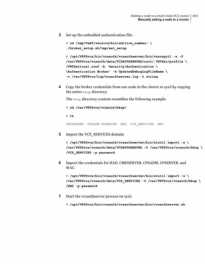
3 Set up the embedded authentication file:
# cd /tmp/VxAT/version/bin/edition_number; \
./broker_setup.sh/tmp/eat_setup
# /opt/VRTSvcs/bin/vcsauth/vcsauthserver/bin/vssregctl -s -f
/var/VRTSvcs/vcsauth/data/VCSAUTHSERVER/root/.VRTSat/profile \
/VRTSatlocal.conf -b 'Security\Authentication \
\Authentication Broker' -k UpdatedDebugLogFileName \
-v /var/VRTSvcs/log/vcsauthserver.log -t string
4 Copy the broker credentials from one node in the cluster to sys5 by copyingthe entire bkup directory.
The bkup directory content resembles the following example:
# cd /var/VRTSvcs/vcsauth/bkup/
# ls
CMDSERVER CPSADM CPSERVER HAD VCS_SERVICES WAC
5 Import the VCS_SERVICES domain.
# /opt/VRTSvcs/bin/vcsauth/vcsauthserver/bin/atutil import -z \
/var/VRTSvcs/vcsauth/data/VCSAUTHSERVER -f /var/VRTSvcs/vcsauth/bkup \
/VCS_SERVICES -p password
6 Import the credentials for HAD, CMDSERVER, CPSADM, CPSERVER, andWAC.
# /opt/VRTSvcs/bin/vcsauth/vcsauthserver/bin/atutil import -z \
/var/VRTSvcs/vcsauth/data/VCS_SERVICES -f /var/VRTSvcs/vcsauth/bkup \
/HAD -p password
7 Start the vcsauthserver process on sys5.
# /opt/VRTSvcs/bin/vcsauth/vcsauthserver/bin/vcsauthserver.sh
403Adding a node to a multi-node VCS clusterManually adding a node to a cluster
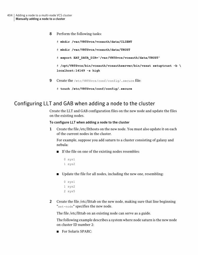
8 Perform the following tasks:
# mkdir /var/VRTSvcs/vcsauth/data/CLIENT
# mkdir /var/VRTSvcs/vcsauth/data/TRUST
# export EAT_DATA_DIR='/var/VRTSvcs/vcsauth/data/TRUST'
# /opt/VRTSvcs/bin/vcsauth/vcsauthserver/bin/vssat setuptrust -b \
localhost:14149 -s high
9 Create the /etc/VRTSvcs/conf/config/.secure file:
# touch /etc/VRTSvcs/conf/config/.secure
Configuring LLT and GAB when adding a node to the clusterCreate the LLT and GAB configuration files on the new node and update the fileson the existing nodes.
To configure LLT when adding a node to the cluster
1 Create the file /etc/llthosts on the new node. You must also update it on eachof the current nodes in the cluster.
For example, suppose you add saturn to a cluster consisting of galaxy andnebula:
■ If the file on one of the existing nodes resembles:
0 sys1
1 sys2
■ Update the file for all nodes, including the new one, resembling:
0 sys1
1 sys2
2 sys5
2 Create the file /etc/llttab on the new node, making sure that line beginning"set-node" specifies the new node.
The file /etc/llttab on an existing node can serve as a guide.
The following example describes a system where node saturn is the new nodeon cluster ID number 2:
■ For Solaris SPARC:
Adding a node to a multi-node VCS clusterManually adding a node to a cluster
404
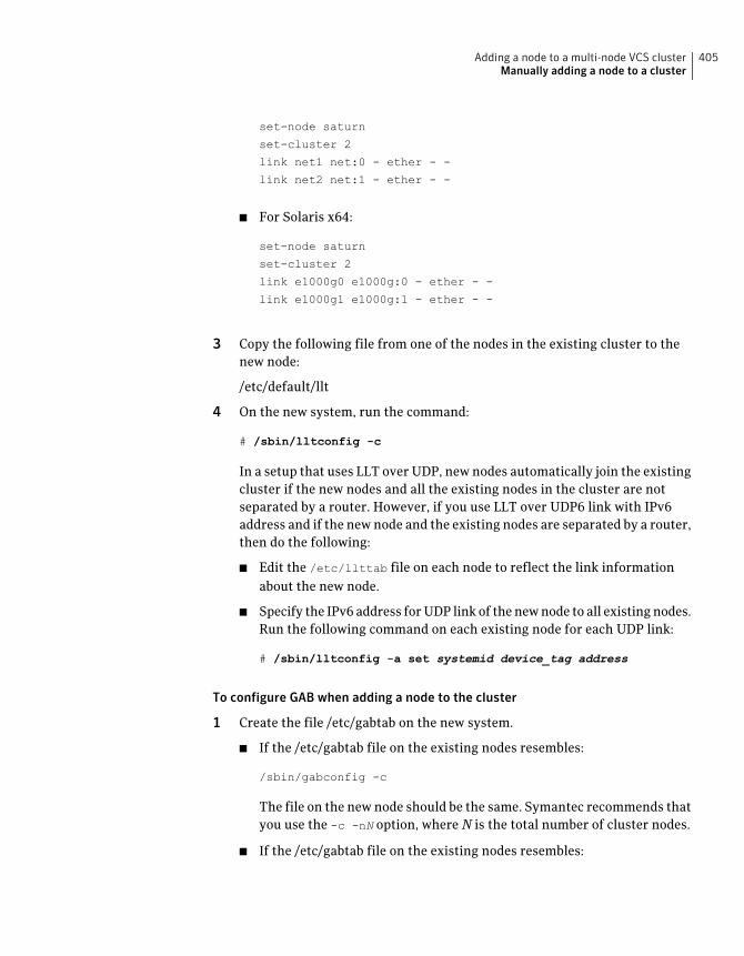
set-node saturn
set-cluster 2
link net1 net:0 - ether - -
link net2 net:1 - ether - -
■ For Solaris x64:
set-node saturn
set-cluster 2
link e1000g0 e1000g:0 - ether - -
link e1000g1 e1000g:1 - ether - -
3 Copy the following file from one of the nodes in the existing cluster to thenew node:
/etc/default/llt
4 On the new system, run the command:
# /sbin/lltconfig -c
In a setup that uses LLT over UDP, new nodes automatically join the existingcluster if the new nodes and all the existing nodes in the cluster are notseparated by a router. However, if you use LLT over UDP6 link with IPv6address and if the new node and the existing nodes are separated by a router,then do the following:
■ Edit the /etc/llttab file on each node to reflect the link informationabout the new node.
■ Specify the IPv6 address for UDP link of the new node to all existing nodes.Run the following command on each existing node for each UDP link:
# /sbin/lltconfig -a set systemid device_tag address
To configure GAB when adding a node to the cluster
1 Create the file /etc/gabtab on the new system.
■ If the /etc/gabtab file on the existing nodes resembles:
/sbin/gabconfig -c
The file on the new node should be the same. Symantec recommends thatyou use the -c -nN option, where N is the total number of cluster nodes.
■ If the /etc/gabtab file on the existing nodes resembles:
405Adding a node to a multi-node VCS clusterManually adding a node to a cluster
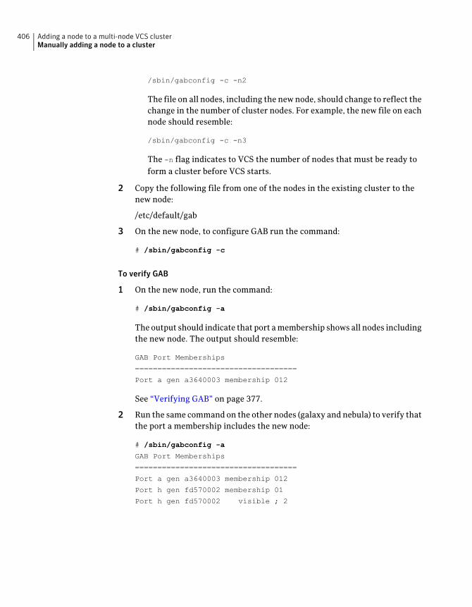
/sbin/gabconfig -c -n2
The file on all nodes, including the new node, should change to reflect thechange in the number of cluster nodes. For example, the new file on eachnode should resemble:
/sbin/gabconfig -c -n3
The -n flag indicates to VCS the number of nodes that must be ready toform a cluster before VCS starts.
2 Copy the following file from one of the nodes in the existing cluster to thenew node:
/etc/default/gab
3 On the new node, to configure GAB run the command:
# /sbin/gabconfig -c
To verify GAB
1 On the new node, run the command:
# /sbin/gabconfig -a
The output should indicate that port a membership shows all nodes includingthe new node. The output should resemble:
GAB Port Memberships
====================================
Port a gen a3640003 membership 012
See “Verifying GAB” on page 377.
2 Run the same command on the other nodes (galaxy and nebula) to verify thatthe port a membership includes the new node:
# /sbin/gabconfig -a
GAB Port Memberships
====================================
Port a gen a3640003 membership 012
Port h gen fd570002 membership 01
Port h gen fd570002 visible ; 2
Adding a node to a multi-node VCS clusterManually adding a node to a cluster
406
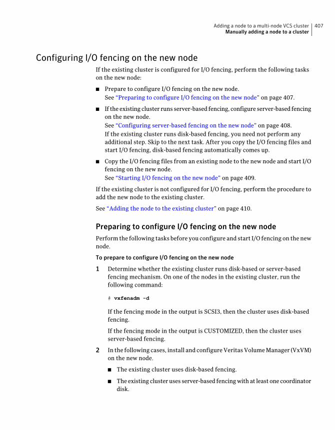
Configuring I/O fencing on the new nodeIf the existing cluster is configured for I/O fencing, perform the following taskson the new node:
■ Prepare to configure I/O fencing on the new node.See “Preparing to configure I/O fencing on the new node” on page 407.
■ If the existing cluster runs server-based fencing, configure server-based fencingon the new node.See “Configuring server-based fencing on the new node” on page 408.If the existing cluster runs disk-based fencing, you need not perform anyadditional step. Skip to the next task. After you copy the I/O fencing files andstart I/O fencing, disk-based fencing automatically comes up.
■ Copy the I/O fencing files from an existing node to the new node and start I/Ofencing on the new node.See “Starting I/O fencing on the new node” on page 409.
If the existing cluster is not configured for I/O fencing, perform the procedure toadd the new node to the existing cluster.
See “Adding the node to the existing cluster” on page 410.
Preparing to configure I/O fencing on the new nodePerform the following tasks before you configure and start I/O fencing on the newnode.
To prepare to configure I/O fencing on the new node
1 Determine whether the existing cluster runs disk-based or server-basedfencing mechanism. On one of the nodes in the existing cluster, run thefollowing command:
# vxfenadm -d
If the fencing mode in the output is SCSI3, then the cluster uses disk-basedfencing.
If the fencing mode in the output is CUSTOMIZED, then the cluster usesserver-based fencing.
2 In the following cases, install and configure Veritas Volume Manager (VxVM)on the new node.
■ The existing cluster uses disk-based fencing.
■ The existing cluster uses server-based fencing with at least one coordinatordisk.
407Adding a node to a multi-node VCS clusterManually adding a node to a cluster
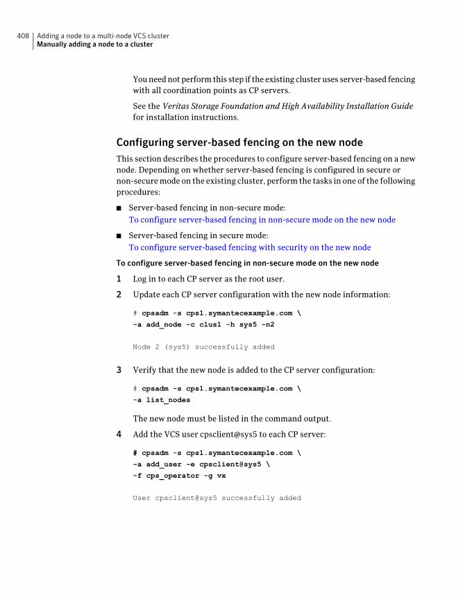
You need not perform this step if the existing cluster uses server-based fencingwith all coordination points as CP servers.
See the Veritas Storage Foundation and High Availability Installation Guidefor installation instructions.
Configuring server-based fencing on the new nodeThis section describes the procedures to configure server-based fencing on a newnode. Depending on whether server-based fencing is configured in secure ornon-secure mode on the existing cluster, perform the tasks in one of the followingprocedures:
■ Server-based fencing in non-secure mode:To configure server-based fencing in non-secure mode on the new node
■ Server-based fencing in secure mode:To configure server-based fencing with security on the new node
To configure server-based fencing in non-secure mode on the new node
1 Log in to each CP server as the root user.
2 Update each CP server configuration with the new node information:
# cpsadm -s cps1.symantecexample.com \
-a add_node -c clus1 -h sys5 -n2
Node 2 (sys5) successfully added
3 Verify that the new node is added to the CP server configuration:
# cpsadm -s cps1.symantecexample.com \
-a list_nodes
The new node must be listed in the command output.
4 Add the VCS user cpsclient@sys5 to each CP server:
# cpsadm -s cps1.symantecexample.com \
-a add_user -e cpsclient@sys5 \
-f cps_operator -g vx
User cpsclient@sys5 successfully added
Adding a node to a multi-node VCS clusterManually adding a node to a cluster
408
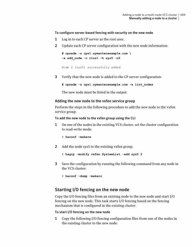
To configure server-based fencing with security on the new node
1 Log in to each CP server as the root user.
2 Update each CP server configuration with the new node information:
# cpsadm -s cps1.symantecexample.com \
-a add_node -c clus1 -h sys5 -n2
Node 2 (sys5) successfully added
3 Verify that the new node is added to the CP server configuration:
# cpsadm -s cps1.symantecexample.com -a list_nodes
The new node must be listed in the output.
Adding the new node to the vxfen service group
Perform the steps in the following procedure to add the new node to the vxfenservice group.
To add the new node to the vxfen group using the CLI
1 On one of the nodes in the existing VCS cluster, set the cluster configurationto read-write mode:
# haconf -makerw
2 Add the node sys5 to the existing vxfen group.
# hagrp -modify vxfen SystemList -add sys5 2
3 Save the configuration by running the following command from any node inthe VCS cluster:
# haconf -dump -makero
Starting I/O fencing on the new nodeCopy the I/O fencing files from an existing node to the new node and start I/Ofencing on the new node. This task starts I/O fencing based on the fencingmechanism that is configured in the existing cluster.
To start I/O fencing on the new node
1 Copy the following I/O fencing configuration files from one of the nodes inthe existing cluster to the new node:
409Adding a node to a multi-node VCS clusterManually adding a node to a cluster
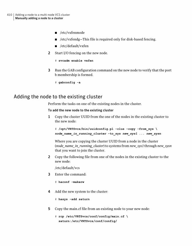
■ /etc/vxfenmode
■ /etc/vxfendg—This file is required only for disk-based fencing.
■ /etc/default/vxfen
2 Start I/O fencing on the new node.
# svcadm enable vxfen
3 Run the GAB configuration command on the new node to verify that the portb membership is formed.
# gabconfig -a
Adding the node to the existing clusterPerform the tasks on one of the existing nodes in the cluster.
To add the new node to the existing cluster
1 Copy the cluster UUID from the one of the nodes in the existing cluster tothe new node:
# /opt/VRTSvcs/bin/uuidconfig.pl -clus -copy -from_sys \
node_name_in_running_cluster -to_sys new_sys1 ... new_sysn
Where you are copying the cluster UUID from a node in the cluster(node_name_in_running_cluster) to systems fromnew_sys1 throughnew_sysnthat you want to join the cluster.
2 Copy the following file from one of the nodes in the existing cluster to thenew node:
/etc/default/vcs
3 Enter the command:
# haconf -makerw
4 Add the new system to the cluster:
# hasys -add saturn
5 Copy the main.cf file from an existing node to your new node:
# rcp /etc/VRTSvcs/conf/config/main.cf \
saturn:/etc/VRTSvcs/conf/config/
Adding a node to a multi-node VCS clusterManually adding a node to a cluster
410
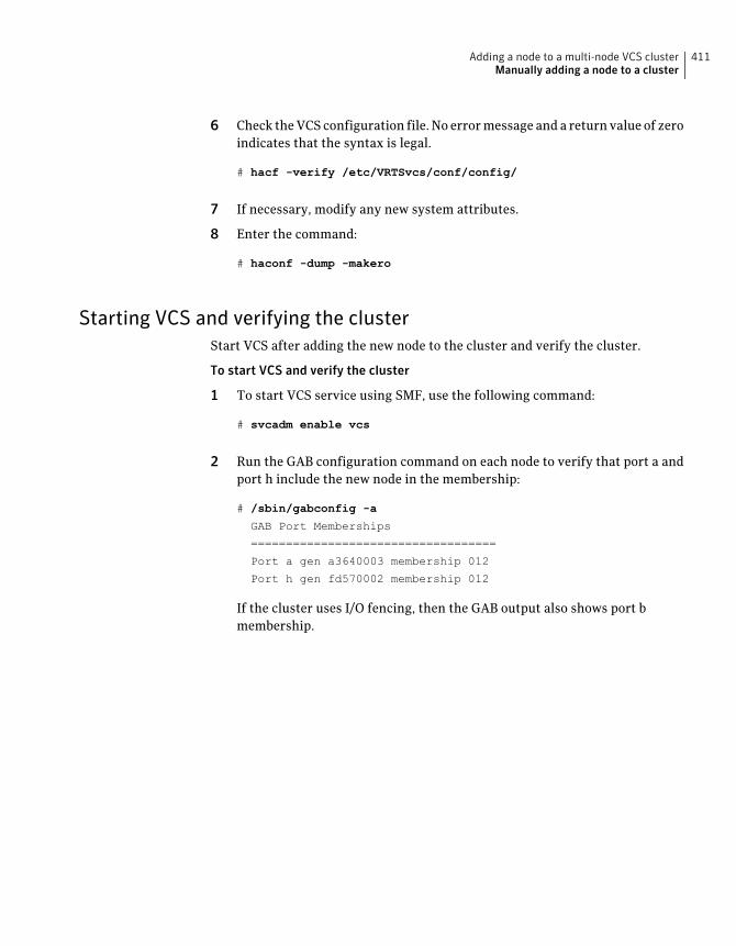
6 Check the VCS configuration file. No error message and a return value of zeroindicates that the syntax is legal.
# hacf -verify /etc/VRTSvcs/conf/config/
7 If necessary, modify any new system attributes.
8 Enter the command:
# haconf -dump -makero
Starting VCS and verifying the clusterStart VCS after adding the new node to the cluster and verify the cluster.
To start VCS and verify the cluster
1 To start VCS service using SMF, use the following command:
# svcadm enable vcs
2 Run the GAB configuration command on each node to verify that port a andport h include the new node in the membership:
# /sbin/gabconfig -a
GAB Port Memberships
===================================
Port a gen a3640003 membership 012
Port h gen fd570002 membership 012
If the cluster uses I/O fencing, then the GAB output also shows port bmembership.
411Adding a node to a multi-node VCS clusterManually adding a node to a cluster

Adding a node to a multi-node VCS clusterManually adding a node to a cluster
412
Removing a node from aVCS cluster
This chapter includes the following topics:
■ Removing a node from a VCS cluster
Removing a node from a VCS clusterTable 30-1 specifies the tasks that are involved in removing a node from a cluster.In the example procedure, the cluster consists of nodes sys1, sys2, and sys5; nodesys5 is to leave the cluster.
Table 30-1 Tasks that are involved in removing a node
ReferenceTask
See “Verifying the status of nodes andservice groups” on page 414.
■ Back up the configuration file.
■ Check the status of the nodes and the servicegroups.
See “Deleting the departing node fromVCS configuration” on page 415.
■ Switch or remove any VCS service groups onthe node departing the cluster.
■ Delete the node from VCS configuration.
See “Modifying configuration files oneach remaining node” on page 418.
Modify the llthosts(4) and gabtab(4) files to reflectthe change.
See “Removing the node configurationfrom the CP server” on page 419.
If the existing cluster is configured to useserver-based I/O fencing, remove the nodeconfiguration from the CP server.
30Chapter
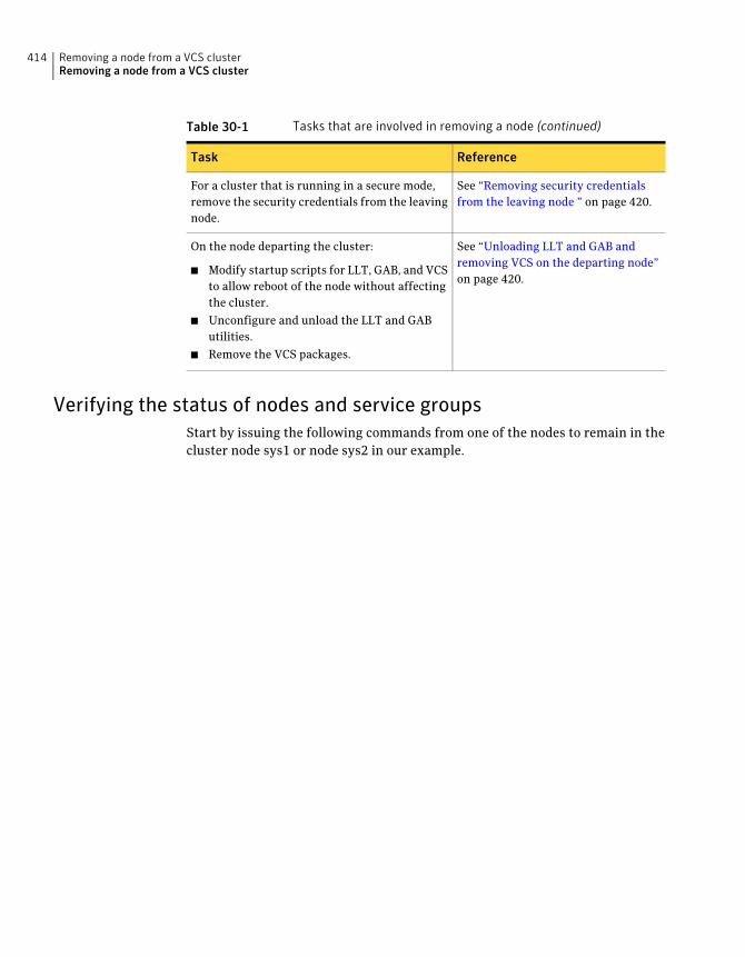
Table 30-1 Tasks that are involved in removing a node (continued)
ReferenceTask
See “Removing security credentialsfrom the leaving node ” on page 420.
For a cluster that is running in a secure mode,remove the security credentials from the leavingnode.
See “Unloading LLT and GAB andremoving VCS on the departing node”on page 420.
On the node departing the cluster:
■ Modify startup scripts for LLT, GAB, and VCSto allow reboot of the node without affectingthe cluster.
■ Unconfigure and unload the LLT and GAButilities.
■ Remove the VCS packages.
Verifying the status of nodes and service groupsStart by issuing the following commands from one of the nodes to remain in thecluster node sys1 or node sys2 in our example.
Removing a node from a VCS clusterRemoving a node from a VCS cluster
414
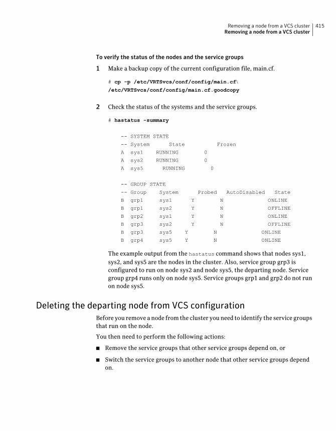
To verify the status of the nodes and the service groups
1 Make a backup copy of the current configuration file, main.cf.
# cp -p /etc/VRTSvcs/conf/config/main.cf\
/etc/VRTSvcs/conf/config/main.cf.goodcopy
2 Check the status of the systems and the service groups.
# hastatus -summary
-- SYSTEM STATE
-- System State Frozen
A sys1 RUNNING 0
A sys2 RUNNING 0
A sys5 RUNNING 0
-- GROUP STATE
-- Group System Probed AutoDisabled State
B grp1 sys1 Y N ONLINE
B grp1 sys2 Y N OFFLINE
B grp2 sys1 Y N ONLINE
B grp3 sys2 Y N OFFLINE
B grp3 sys5 Y N ONLINE
B grp4 sys5 Y N ONLINE
The example output from the hastatus command shows that nodes sys1,sys2, and sys5 are the nodes in the cluster. Also, service group grp3 isconfigured to run on node sys2 and node sys5, the departing node. Servicegroup grp4 runs only on node sys5. Service groups grp1 and grp2 do not runon node sys5.
Deleting the departing node from VCS configurationBefore you remove a node from the cluster you need to identify the service groupsthat run on the node.
You then need to perform the following actions:
■ Remove the service groups that other service groups depend on, or
■ Switch the service groups to another node that other service groups dependon.
415Removing a node from a VCS clusterRemoving a node from a VCS cluster

To remove or switch service groups from the departing node
1 Switch failover service groups from the departing node. You can switch grp3from node sys5 to node sys2.
# hagrp -switch grp3 -to sys2
2 Check for any dependencies involving any service groups that run on thedeparting node; for example, grp4 runs only on the departing node.
# hagrp -dep
3 If the service group on the departing node requires other service groups—ifit is a parent to service groups on other nodes—unlink the service groups.
# haconf -makerw
# hagrp -unlink grp4 grp1
These commands enable you to edit the configuration and to remove therequirement grp4 has for grp1.
4 Stop VCS on the departing node:
# hastop -sys sys5
To stop VCS using SMF, run the following command:
# svcadm disable vcs
Removing a node from a VCS clusterRemoving a node from a VCS cluster
416
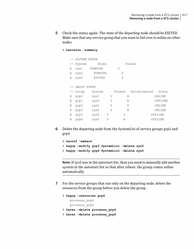
5 Check the status again. The state of the departing node should be EXITED.Make sure that any service group that you want to fail over is online on othernodes.
# hastatus -summary
-- SYSTEM STATE
-- System State Frozen
A sys1 RUNNING 0
A sys2 RUNNING 0
A sys5 EXITED 0
-- GROUP STATE
-- Group System Probed AutoDisabled State
B grp1 sys1 Y N ONLINE
B grp1 sys2 Y N OFFLINE
B grp2 sys1 Y N ONLINE
B grp3 sys2 Y N ONLINE
B grp3 sys5 Y Y OFFLINE
B grp4 sys5 Y N OFFLINE
6 Delete the departing node from the SystemList of service groups grp3 andgrp4.
# haconf -makerw
# hagrp -modify grp3 SystemList -delete sys5
# hagrp -modify grp4 SystemList -delete sys5
Note: If sys5 was in the autostart list, then you need to manually add anothersystem in the autostart list so that after reboot, the group comes onlineautomatically.
7 For the service groups that run only on the departing node, delete theresources from the group before you delete the group.
# hagrp -resources grp4
processx_grp4
processy_grp4
# hares -delete processx_grp4
# hares -delete processy_grp4
417Removing a node from a VCS clusterRemoving a node from a VCS cluster
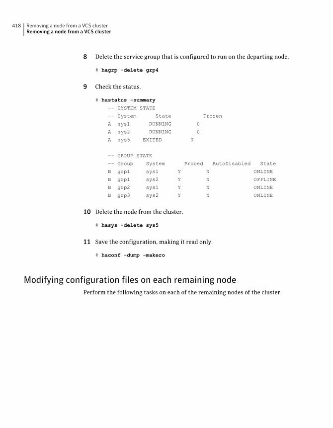
8 Delete the service group that is configured to run on the departing node.
# hagrp -delete grp4
9 Check the status.
# hastatus -summary
-- SYSTEM STATE
-- System State Frozen
A sys1 RUNNING 0
A sys2 RUNNING 0
A sys5 EXITED 0
-- GROUP STATE
-- Group System Probed AutoDisabled State
B grp1 sys1 Y N ONLINE
B grp1 sys2 Y N OFFLINE
B grp2 sys1 Y N ONLINE
B grp3 sys2 Y N ONLINE
10 Delete the node from the cluster.
# hasys -delete sys5
11 Save the configuration, making it read only.
# haconf -dump -makero
Modifying configuration files on each remaining nodePerform the following tasks on each of the remaining nodes of the cluster.
Removing a node from a VCS clusterRemoving a node from a VCS cluster
418
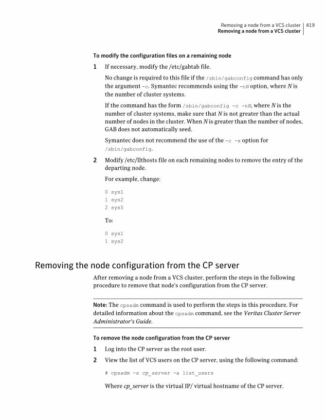
To modify the configuration files on a remaining node
1 If necessary, modify the /etc/gabtab file.
No change is required to this file if the /sbin/gabconfig command has onlythe argument -c. Symantec recommends using the -nN option, where N isthe number of cluster systems.
If the command has the form /sbin/gabconfig -c -nN, where N is thenumber of cluster systems, make sure that N is not greater than the actualnumber of nodes in the cluster. WhenN is greater than the number of nodes,GAB does not automatically seed.
Symantec does not recommend the use of the -c -x option for/sbin/gabconfig.
2 Modify /etc/llthosts file on each remaining nodes to remove the entry of thedeparting node.
For example, change:
0 sys1
1 sys2
2 sys5
To:
0 sys1
1 sys2
Removing the node configuration from the CP serverAfter removing a node from a VCS cluster, perform the steps in the followingprocedure to remove that node's configuration from the CP server.
Note: The cpsadm command is used to perform the steps in this procedure. Fordetailed information about the cpsadm command, see the Veritas Cluster ServerAdministrator's Guide.
To remove the node configuration from the CP server
1 Log into the CP server as the root user.
2 View the list of VCS users on the CP server, using the following command:
# cpsadm -s cp_server -a list_users
Where cp_server is the virtual IP/ virtual hostname of the CP server.
419Removing a node from a VCS clusterRemoving a node from a VCS cluster
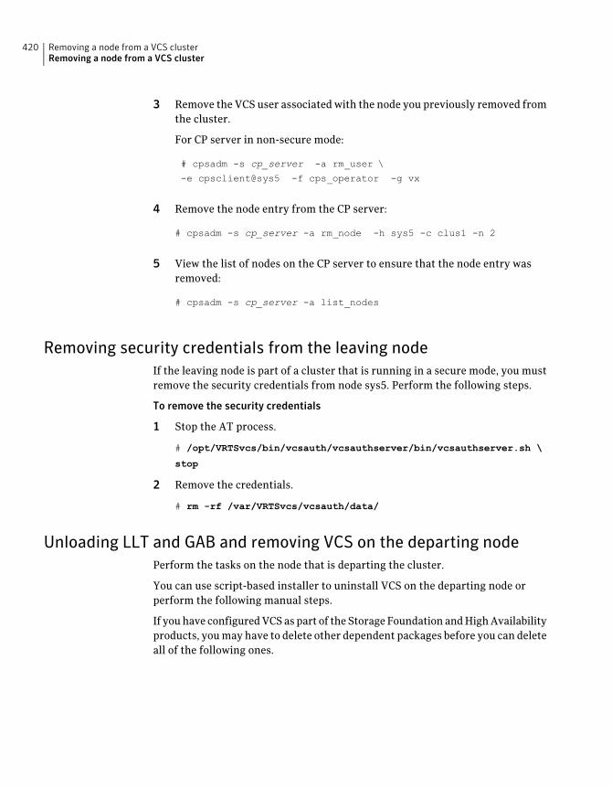
3 Remove the VCS user associated with the node you previously removed fromthe cluster.
For CP server in non-secure mode:
# cpsadm -s cp_server -a rm_user \
-e cpsclient@sys5 -f cps_operator -g vx
4 Remove the node entry from the CP server:
# cpsadm -s cp_server -a rm_node -h sys5 -c clus1 -n 2
5 View the list of nodes on the CP server to ensure that the node entry wasremoved:
# cpsadm -s cp_server -a list_nodes
Removing security credentials from the leaving nodeIf the leaving node is part of a cluster that is running in a secure mode, you mustremove the security credentials from node sys5. Perform the following steps.
To remove the security credentials
1 Stop the AT process.
# /opt/VRTSvcs/bin/vcsauth/vcsauthserver/bin/vcsauthserver.sh \
stop
2 Remove the credentials.
# rm -rf /var/VRTSvcs/vcsauth/data/
Unloading LLT and GAB and removing VCS on the departing nodePerform the tasks on the node that is departing the cluster.
You can use script-based installer to uninstall VCS on the departing node orperform the following manual steps.
If you have configured VCS as part of the Storage Foundation and High Availabilityproducts, you may have to delete other dependent packages before you can deleteall of the following ones.
Removing a node from a VCS clusterRemoving a node from a VCS cluster
420
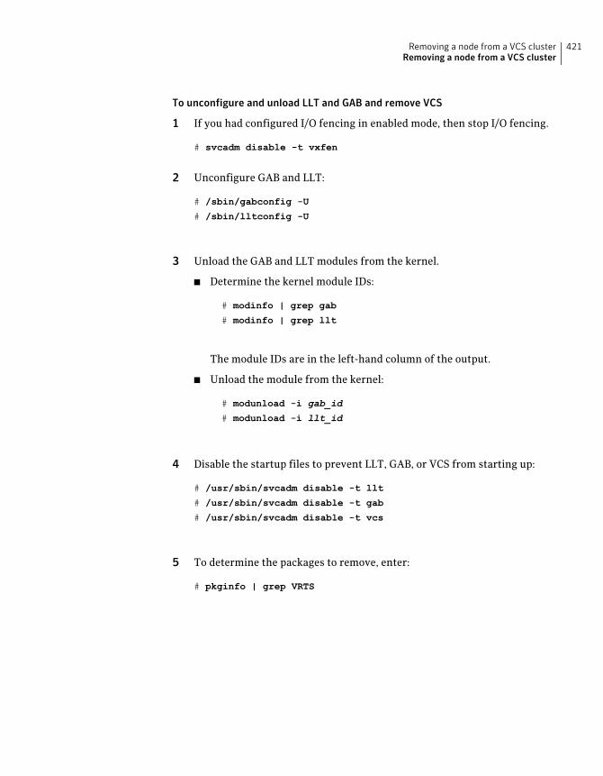
To unconfigure and unload LLT and GAB and remove VCS
1 If you had configured I/O fencing in enabled mode, then stop I/O fencing.
# svcadm disable -t vxfen
2 Unconfigure GAB and LLT:
# /sbin/gabconfig -U
# /sbin/lltconfig -U
3 Unload the GAB and LLT modules from the kernel.
■ Determine the kernel module IDs:
# modinfo | grep gab
# modinfo | grep llt
The module IDs are in the left-hand column of the output.
■ Unload the module from the kernel:
# modunload -i gab_id
# modunload -i llt_id
4 Disable the startup files to prevent LLT, GAB, or VCS from starting up:
# /usr/sbin/svcadm disable -t llt
# /usr/sbin/svcadm disable -t gab
# /usr/sbin/svcadm disable -t vcs
5 To determine the packages to remove, enter:
# pkginfo | grep VRTS
421Removing a node from a VCS clusterRemoving a node from a VCS cluster
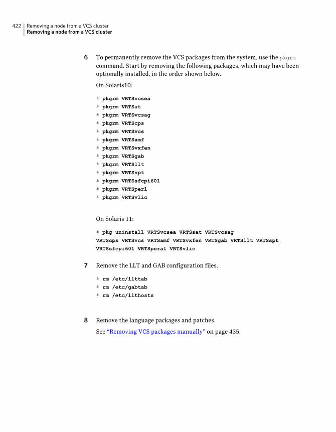
6 To permanently remove the VCS packages from the system, use the pkgrm
command. Start by removing the following packages, which may have beenoptionally installed, in the order shown below.
On Solaris10:
# pkgrm VRTSvcsea
# pkgrm VRTSat
# pkgrm VRTSvcsag
# pkgrm VRTScps
# pkgrm VRTSvcs
# pkgrm VRTSamf
# pkgrm VRTSvxfen
# pkgrm VRTSgab
# pkgrm VRTSllt
# pkgrm VRTSspt
# pkgrm VRTSsfcpi601
# pkgrm VRTSperl
# pkgrm VRTSvlic
On Solaris 11:
# pkg uninstall VRTSvcsea VRTSsat VRTSvcsag
VRTScps VRTSvcs VRTSamf VRTSvxfen VRTSgab VRTSllt VRTSspt
VRTSsfcpi601 VRTSperal VRTSvlic
7 Remove the LLT and GAB configuration files.
# rm /etc/llttab
# rm /etc/gabtab
# rm /etc/llthosts
8 Remove the language packages and patches.
See “Removing VCS packages manually” on page 435.
Removing a node from a VCS clusterRemoving a node from a VCS cluster
422
Uninstallation of VCS
■ Chapter 31. Uninstalling VCS using the installer
■ Chapter 32. Uninstalling VCS using response files
■ Chapter 33. Manually uninstalling VCS
10Section

424
Uninstalling VCS using theinstaller
This chapter includes the following topics:
■ Preparing to uninstall VCS
■ Uninstalling VCS using the script-based installer
■ Uninstalling VCS with the Veritas Web-based installer
■ Removing language packages using the uninstaller program
■ Removing the CP server configuration using the installer program
Preparing to uninstall VCSReview the following prerequisites before you uninstall VCS:
■ Before you remove VCS from any node in the cluster, shut down theapplications that depend on VCS. For example, applications such as JavaConsole or any high availability agents for VCS.
■ Before you remove VCS from fewer than all nodes in a cluster, stop the servicegroups on the nodes from which you uninstall VCS. You must also reconfigureVCS on the remaining nodes.
■ If you have manually edited any of the VCS configuration files, you need toreformat them.See “Reformatting VCS configuration files on a stopped cluster” on page 77.
31Chapter
Uninstalling VCS using the script-based installerYou must meet the following conditions to use the uninstallvcs program touninstall VCS on all nodes in the cluster at one time:
■ Make sure that the communication exists between systems. By default, theuninstaller uses ssh.
■ Make sure you can execute ssh or rsh commands as superuser on all nodes inthe cluster.
■ Make sure that the ssh or rsh is configured to operate without requests forpasswords or passphrases.
If you cannot meet the prerequisites, then you must run the uninstallvcs programon each node in the cluster.
The uninstallvcs program removes all VCS packages and VCS language packages.
The example demonstrates how to uninstall VCS using the uninstallvcs program.The uninstallvcs program uninstalls VCS on two nodes: sys1 sys2. The exampleprocedure uninstalls VCS from all nodes in the cluster.
Note: If already present on the system, the uninstallation does not remove theVRTSacclib package.
Removing VCS 6.0.1 packagesThe program stops the VCS processes that are currently running during theuninstallation process.
To uninstall VCS
1 Log in as superuser from the node where you want to uninstall VCS.
2 Start uninstallvcs program.
# cd /opt/VRTS/install
# ./uninstallvcs<version>
Where <version> is the specific release version.
See “About the Veritas installer” on page 46.
The program specifies the directory where the logs are created. The programdisplays a copyright notice and a description of the cluster:
Uninstalling VCS using the installerUninstalling VCS using the script-based installer
426
3 Enter the names of the systems from which you want to uninstall VCS.
The program performs system verification checks and asks to stop all runningVCS processes.
4 Enter y to stop all the VCS processes.
The program stops the VCS processes and proceeds with uninstalling thesoftware.
5 Review the output as the uninstallvcs program continues to do the following:
■ Verifies the communication between systems
■ Checks the installations on each system to determine the packages to beuninstalled.
6 Review the output as the uninstaller stops processes, unloads kernel modules,and removes the packages.
7 Note the location of summary, response, and log files that the uninstallercreates after removing all the packages.
Running uninstallvcs from the VCS 6.0.1 discYou may need to use the uninstallvcs program on the VCS 6.0.1 disc in one of thefollowing cases:
■ You need to uninstall VCS after an incomplete installation.
■ The uninstallvcs program is not available in /opt/VRTS/install.
If you mounted the installation media to /mnt, access the uninstallvcs programby changing directory to:
cd /mnt/cluster_server/
./uninstallvcs
Uninstalling VCSwith theVeritasWeb-based installerThis section describes how to uninstall using the Veritas Web-based installer.
Note: After you uninstall the product, you cannot access any file systems youcreated using the default disk layout Version in VCS 6.0.1 with a previous versionof VCS.
427Uninstalling VCS using the installerUninstalling VCS with the Veritas Web-based installer
To uninstall VCS
1 Perform the required steps to save any data that you wish to preserve. Forexample, take back-ups of configuration files.
2 Start the Web-based installer.
See “Starting the Veritas Web-based installer” on page 176.
3 On the Select a task and a product page, select Uninstall a Product from theTask drop-down list.
4 Select Veritas Cluster Server from the Product drop-down list, and clickNext.
5 Indicate the systems on which to uninstall. Enter one or more system names,separated by spaces. Click Next.
6 After the validation completes successfully, click Next to uninstall VCS onthe selected system.
7 If there are any processes running on the target system, the installer stopsthe processes. Click Next.
8 After the installer stops the processes, the installer removes the productsfrom the specified system.
Click Next.
9 After the uninstall completes, the installer displays the location of thesummary, response, and log files. If required, view the files to confirm thestatus of the removal.
10 Click Finish.
Most RPMs have kernel components. In order to ensure their completeremoval, a system reboot is recommended after all the RPMs have beenremoved.
Note: If already present on the system, the uninstallation does not remove theVRTSacclib package.
Removing language packages using the uninstallerprogram
The uninstallvcs program removes all VCS packages and language packages.
Uninstalling VCS using the installerRemoving language packages using the uninstaller program
428
Removing the CP server configuration using theinstaller program
This section describes how to remove the CP server configuration from a node ora cluster that hosts the CP server.
Warning: Ensure that no VCS cluster (application cluster) uses the CP server thatyou want to unconfigure.
To remove the CP server configuration
1 To run the configuration removal script, enter the following command onthe node where you want to remove the CP server configuration:
# /opt/VRTS/install/installvcsversion -configcps
2 Select option 3 from the menu to unconfigure the CP server.
VERITAS COORDINATION POINT SERVER CONFIGURATION UTILITY
=======================================================
Select one of the following:
[1] Configure Coordination Point Server on single node VCS system
[2] Configure Coordination Point Server on SFHA cluster
[3] Unconfigure Coordination Point Server
3 Review the warning message and confirm that you want to unconfigure theCP server.
WARNING: Unconfiguring Coordination Point Server stops the
vxcpserv process. VCS clusters using this server for
coordination purpose will have one less coordination point.
Are you sure you want to bring down the cp server? (y/n)
(Default:n) :y
4 Review the screen output as the script performs the following steps to removethe CP server configuration:
429Uninstalling VCS using the installerRemoving the CP server configuration using the installer program
■ Stops the CP server
■ Removes the CP server from VCS configuration
■ Removes resource dependencies
■ Takes the the CP server service group (CPSSG) offline, if it is online
■ Removes the CPSSG service group from the VCS configuration
■ Successfully unconfigured the Veritas Coordination Point Server
The CP server database is not being deleted on the shared storage.
It can be re-used if CP server is reconfigured on the cluster.
The same database location can be specified during CP server configuration.
5 Decide if you want to delete the CP server configuration file.
Do you want to delete the CP Server configuration file (/etc/vxcps.conf)
and log files (in /var/VRTScps)? [y,n,q] (n) y
Deleting /etc/vxcps.conf and log files on sys1.... Done
Deleting /etc/vxcps.conf and log files on sys2... Done
6 Confirm if you want to send information about this installation to Symantecto help improve installation in the future.
Would you like to send the information about this installation
to Symantec to help improve installation in the future? [y,n,q,?] (y)
Upload completed successfully.
Uninstalling VCS using the installerRemoving the CP server configuration using the installer program
430
Uninstalling VCS usingresponse files
This chapter includes the following topics:
■ Uninstalling VCS using response files
■ Response file variables to uninstall VCS
■ Sample response file for uninstalling VCS
Uninstalling VCS using response filesTypically, you can use the response file that the installer generates after youperform VCS uninstallation on one cluster to uninstall VCS on other clusters.
To perform an automated uninstallation
1 Make sure that you meet the prerequisites to uninstall VCS.
2 Copy the response file to the system where you want to uninstall VCS.
See “Sample response file for uninstalling VCS” on page 433.
32Chapter
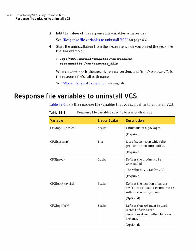
3 Edit the values of the response file variables as necessary.
See “Response file variables to uninstall VCS” on page 432.
4 Start the uninstallation from the system to which you copied the responsefile. For example:
# /opt/VRTS/install/uninstallvcs<version>
-responsefile /tmp/response_file
Where <version> is the specific release version, and /tmp/response_file isthe response file’s full path name.
See “About the Veritas installer” on page 46.
Response file variables to uninstall VCSTable 32-1 lists the response file variables that you can define to uninstall VCS.
Table 32-1 Response file variables specific to uninstalling VCS
DescriptionList or ScalarVariable
Uninstalls VCS packages.
(Required)
ScalarCFG{opt}{uninstall}
List of systems on which theproduct is to be uninstalled.
(Required)
ListCFG{systems}
Defines the product to beuninstalled.
The value is VCS60 for VCS.
(Required)
ScalarCFG{prod}
Defines the location of an sshkeyfile that is used to communicatewith all remote systems.
(Optional)
ScalarCFG{opt}{keyfile}
Defines that rsh must be usedinstead of ssh as thecommunication method betweensystems.
(Optional)
ScalarCFG{opt}{rsh}
Uninstalling VCS using response filesResponse file variables to uninstall VCS
432
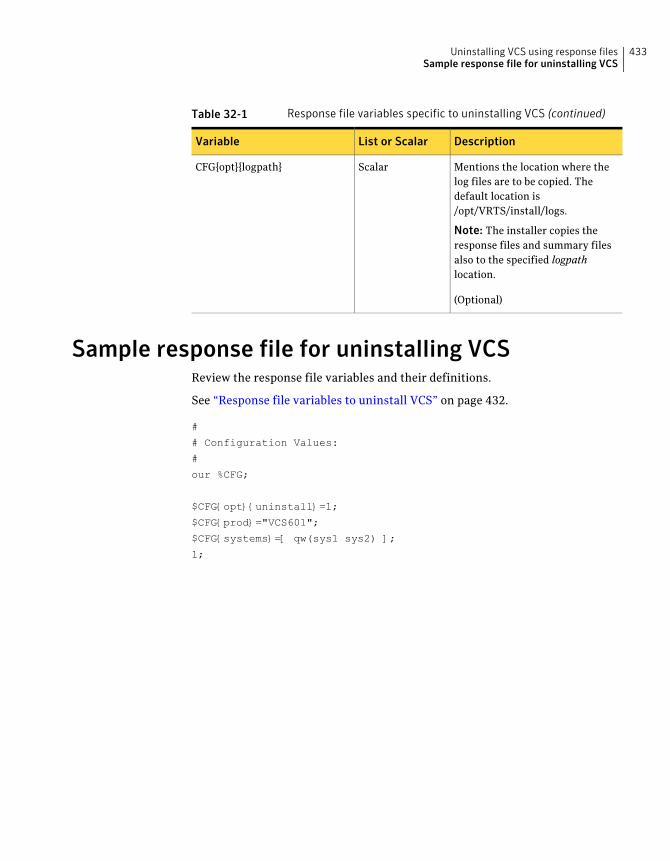
Table 32-1 Response file variables specific to uninstalling VCS (continued)
DescriptionList or ScalarVariable
Mentions the location where thelog files are to be copied. Thedefault location is/opt/VRTS/install/logs.
Note: The installer copies theresponse files and summary filesalso to the specified logpathlocation.
(Optional)
ScalarCFG{opt}{logpath}
Sample response file for uninstalling VCSReview the response file variables and their definitions.
See “Response file variables to uninstall VCS” on page 432.
#
# Configuration Values:
#
our %CFG;
$CFG{opt}{uninstall}=1;
$CFG{prod}="VCS601";
$CFG{systems}=[ qw(sys1 sys2) ];
1;
433Uninstalling VCS using response filesSample response file for uninstalling VCS

Uninstalling VCS using response filesSample response file for uninstalling VCS
434
Manually uninstalling VCS
This chapter includes the following topics:
■ Removing VCS packages manually
■ Manually remove the CP server fencing configuration
■ Manually deleting cluster details from a CP server
■ Manually uninstalling VCS packages on non-global zones on Solaris 11
Removing VCS packages manuallyYou must remove the VCS packages from each node in the cluster to uninstallVCS.
To manually remove VCS packages on a node
1 Shut down VCS on the local system using the hastop command.
# hastop -local
2 Unconfigure the fencing, GAB, LLT, and AMF modules.
# /sbin/vxfenconfig -U
# /sbin/gabconfig -U
# /sbin/lltconfig -U
# /opt/VRTSamf/bin/amfconfig -U
3 Determine the GAB kernel module ID:
# modinfo | grep gab
The module ID is in the left-hand column of the output.
33Chapter

4 Unload the GAB module from the kernel:
# modunload -i gab_id
5 Determine the LLT kernel module ID:
# modinfo | grep llt
The module ID is in the left-hand column of the output.
6 Unload the LLT module from the kernel:
# modunload -i llt_id
7 Determine the AMF kernel module ID:
# modinfo | grep amf
8 Unload the AMF module from the kernel:
# modunload -i amf_id
Manually uninstalling VCSRemoving VCS packages manually
436
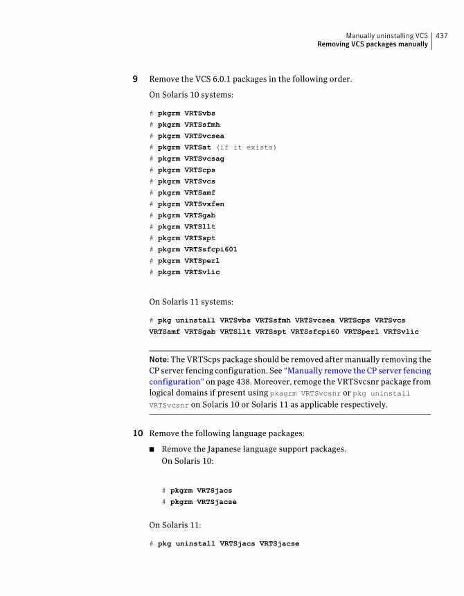
9 Remove the VCS 6.0.1 packages in the following order.
On Solaris 10 systems:
# pkgrm VRTSvbs
# pkgrm VRTSsfmh
# pkgrm VRTSvcsea
# pkgrm VRTSat (if it exists)
# pkgrm VRTSvcsag
# pkgrm VRTScps
# pkgrm VRTSvcs
# pkgrm VRTSamf
# pkgrm VRTSvxfen
# pkgrm VRTSgab
# pkgrm VRTSllt
# pkgrm VRTSspt
# pkgrm VRTSsfcpi601
# pkgrm VRTSperl
# pkgrm VRTSvlic
On Solaris 11 systems:
# pkg uninstall VRTSvbs VRTSsfmh VRTSvcsea VRTScps VRTSvcs
VRTSamf VRTSgab VRTSllt VRTSspt VRTSsfcpi60 VRTSperl VRTSvlic
Note:The VRTScps package should be removed after manually removing theCP server fencing configuration. See “Manually remove the CP server fencingconfiguration” on page 438. Moreover, remoge the VRTSvcsnr package fromlogical domains if present using pkagrm VRTSvcsnr or pkg uninstall
VRTSvcsnr on Solaris 10 or Solaris 11 as applicable respectively.
10 Remove the following language packages:
■ Remove the Japanese language support packages.On Solaris 10:
# pkgrm VRTSjacs
# pkgrm VRTSjacse
On Solaris 11:
# pkg uninstall VRTSjacs VRTSjacse
437Manually uninstalling VCSRemoving VCS packages manually
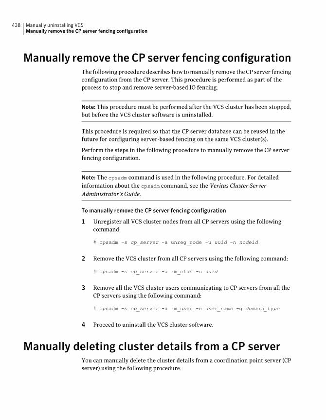
Manually remove the CP server fencing configurationThe following procedure describes how to manually remove the CP server fencingconfiguration from the CP server. This procedure is performed as part of theprocess to stop and remove server-based IO fencing.
Note: This procedure must be performed after the VCS cluster has been stopped,but before the VCS cluster software is uninstalled.
This procedure is required so that the CP server database can be reused in thefuture for configuring server-based fencing on the same VCS cluster(s).
Perform the steps in the following procedure to manually remove the CP serverfencing configuration.
Note: The cpsadm command is used in the following procedure. For detailedinformation about the cpsadm command, see the Veritas Cluster ServerAdministrator's Guide.
To manually remove the CP server fencing configuration
1 Unregister all VCS cluster nodes from all CP servers using the followingcommand:
# cpsadm -s cp_server -a unreg_node -u uuid -n nodeid
2 Remove the VCS cluster from all CP servers using the following command:
# cpsadm -s cp_server -a rm_clus -u uuid
3 Remove all the VCS cluster users communicating to CP servers from all theCP servers using the following command:
# cpsadm -s cp_server -a rm_user -e user_name -g domain_type
4 Proceed to uninstall the VCS cluster software.
Manually deleting cluster details from a CP serverYou can manually delete the cluster details from a coordination point server (CPserver) using the following procedure.
Manually uninstalling VCSManually remove the CP server fencing configuration
438
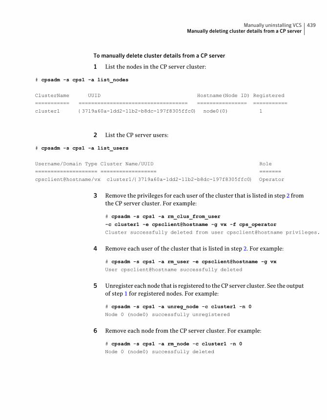
To manually delete cluster details from a CP server
1 List the nodes in the CP server cluster:
# cpsadm -s cps1 -a list_nodes
ClusterName UUID Hostname(Node ID) Registered
=========== =================================== ================ ===========
cluster1 {3719a60a-1dd2-11b2-b8dc-197f8305ffc0} node0(0) 1
2 List the CP server users:
# cpsadm -s cps1 -a list_users
Username/Domain Type Cluster Name/UUID Role
==================== ================== =======
cpsclient@hostname/vx cluster1/{3719a60a-1dd2-11b2-b8dc-197f8305ffc0} Operator
3 Remove the privileges for each user of the cluster that is listed in step 2 fromthe CP server cluster. For example:
# cpsadm -s cps1 -a rm_clus_from_user
-c cluster1 -e cpsclient@hostname -g vx -f cps_operator
Cluster successfully deleted from user cpsclient@hostname privileges.
4 Remove each user of the cluster that is listed in step 2. For example:
# cpsadm -s cps1 -a rm_user -e cpsclient@hostname -g vx
User cpsclient@hostname successfully deleted
5 Unregister each node that is registered to the CP server cluster. See the outputof step 1 for registered nodes. For example:
# cpsadm -s cps1 -a unreg_node -c cluster1 -n 0
Node 0 (node0) successfully unregistered
6 Remove each node from the CP server cluster. For example:
# cpsadm -s cps1 -a rm_node -c cluster1 -n 0
Node 0 (node0) successfully deleted
439Manually uninstalling VCSManually deleting cluster details from a CP server
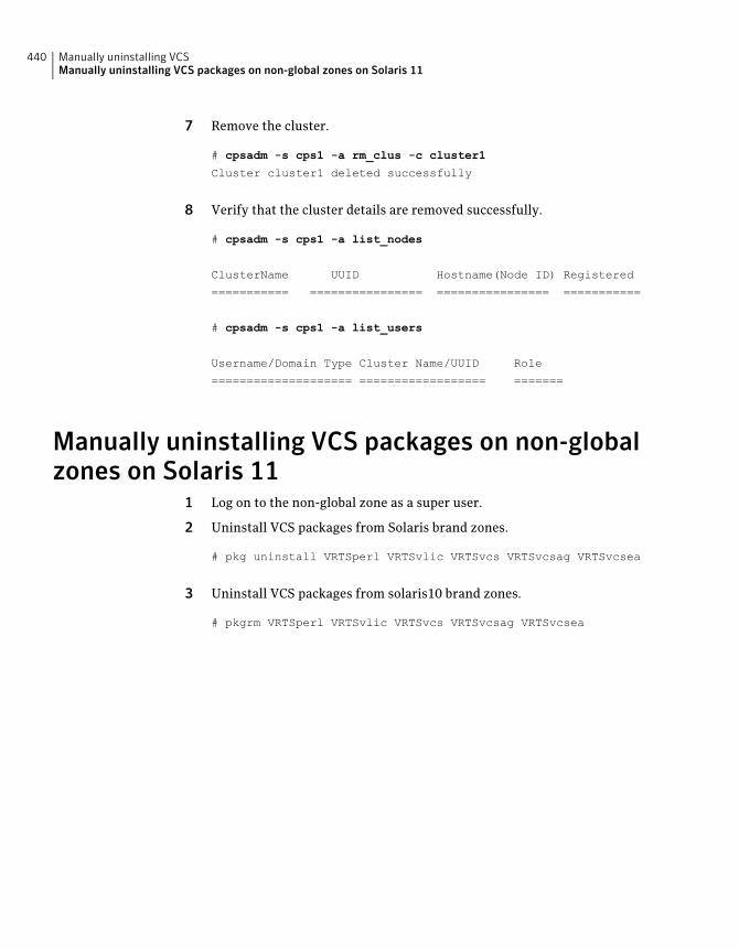
7 Remove the cluster.
# cpsadm -s cps1 -a rm_clus -c cluster1
Cluster cluster1 deleted successfully
8 Verify that the cluster details are removed successfully.
# cpsadm -s cps1 -a list_nodes
ClusterName UUID Hostname(Node ID) Registered
=========== ================ ================ ===========
# cpsadm -s cps1 -a list_users
Username/Domain Type Cluster Name/UUID Role
==================== ================== =======
Manually uninstalling VCS packages on non-globalzones on Solaris 11
1 Log on to the non-global zone as a super user.
2 Uninstall VCS packages from Solaris brand zones.
# pkg uninstall VRTSperl VRTSvlic VRTSvcs VRTSvcsag VRTSvcsea
3 Uninstall VCS packages from solaris10 brand zones.
# pkgrm VRTSperl VRTSvlic VRTSvcs VRTSvcsag VRTSvcsea
Manually uninstalling VCSManually uninstalling VCS packages on non-global zones on Solaris 11
440
Installation reference
■ Appendix A. Services and ports
■ Appendix B. VCS installation packages
■ Appendix C. Installation command options
■ Appendix D. Changes to bundled agents in VCS 6.0.1
■ Appendix E. Configuration files
■ Appendix F. Installing VCS on a single node
■ Appendix G. Configuring LLT over UDP
■ Appendix H. Configuring the secure shell or the remote shell forcommunications
■ Appendix I. Troubleshooting VCS installation
■ Appendix J. Sample VCS cluster setup diagrams for CP server-based I/O fencing
■ Appendix K. Reconciling major/minor numbers for NFS shared disks
■ Appendix L. Compatability issues when installing Veritas Cluster Server withother products
11Section

442
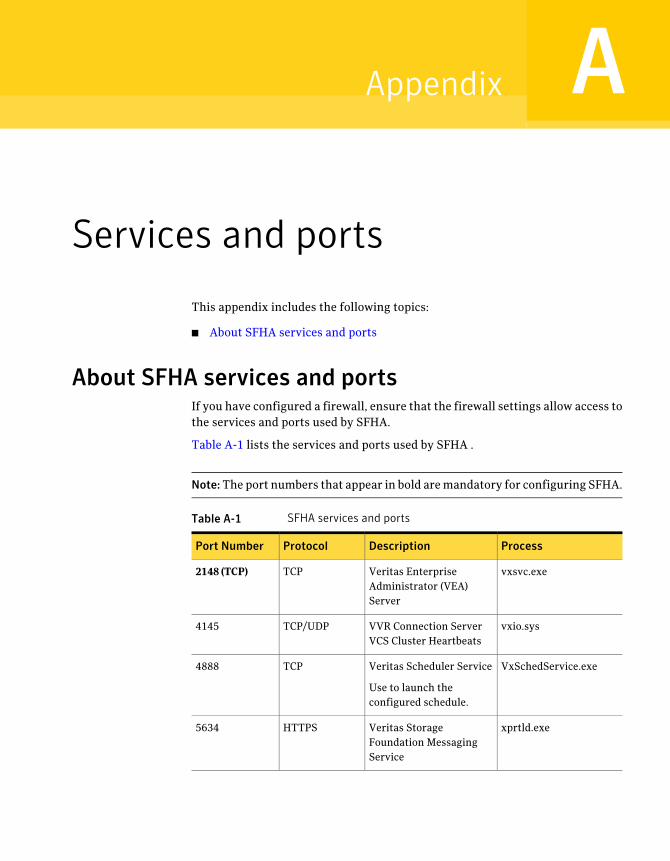
Services and ports
This appendix includes the following topics:
■ About SFHA services and ports
About SFHA services and portsIf you have configured a firewall, ensure that the firewall settings allow access tothe services and ports used by SFHA.
Table A-1 lists the services and ports used by SFHA .
Note:The port numbers that appear in bold are mandatory for configuring SFHA.
Table A-1 SFHA services and ports
ProcessDescriptionProtocolPort Number
vxsvc.exeVeritas EnterpriseAdministrator (VEA)Server
TCP2148 (TCP)
vxio.sysVVR Connection ServerVCS Cluster Heartbeats
TCP/UDP4145
VxSchedService.exeVeritas Scheduler Service
Use to launch theconfigured schedule.
TCP4888
xprtld.exeVeritas StorageFoundation MessagingService
HTTPS5634
AAppendix
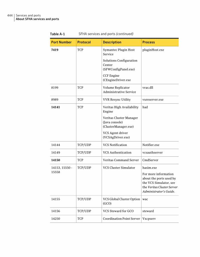
Table A-1 SFHA services and ports (continued)
ProcessDescriptionProtocolPort Number
pluginHost.exeSymantec Plugin HostService
Solutions ConfigurationCenter(SFWConfigPanel.exe)
CCF Engine(CEngineDriver.exe
TCP7419
vras.dllVolume ReplicatorAdministrative Service
TCP8199
vxreserver.exeVVR Resync UtilityTCP8989
hadVeritas High AvailabilityEngine
Veritas Cluster Manager(Java console)(ClusterManager.exe)
VCS Agent driver(VCSAgDriver.exe)
TCP14141
Notifier.exeVCS NotificationTCP/UDP14144
vcsauthserverVCS AuthenticationTCP/UDP14149
CmdServerVeritas Command ServerTCP14150
hasim.exe
For more informationabout the ports used bythe VCS Simulator, seetheVeritasClusterServerAdministrator's Guide.
VCS Cluster SimulatorTCP/UDP14153, 15550 -15558
wacVCS Global Cluster Option(GCO)
TCP/UDP14155
stewardVCS Steward for GCOTCP/UDP14156
VxcpservCoordination Point ServerTCP14250
Services and portsAbout SFHA services and ports
444
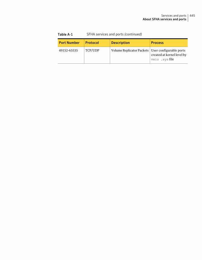
Table A-1 SFHA services and ports (continued)
ProcessDescriptionProtocolPort Number
User configurable portscreated at kernel level byvxio .sys file
Volume Replicator PacketsTCP/UDP49152-65535
445Services and portsAbout SFHA services and ports

Services and portsAbout SFHA services and ports
446
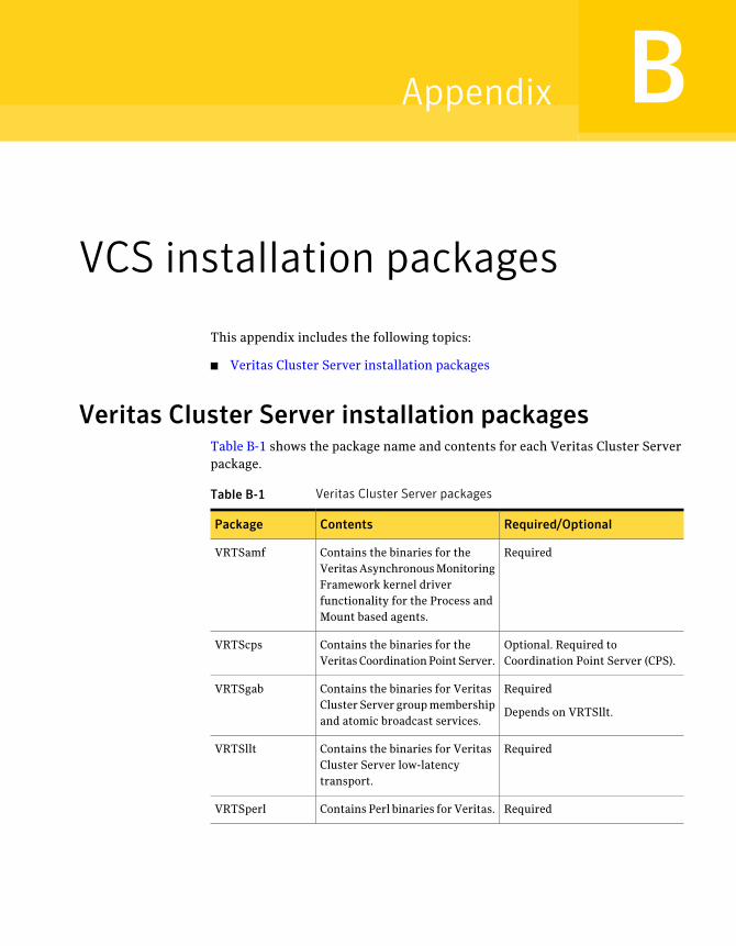
VCS installation packages
This appendix includes the following topics:
■ Veritas Cluster Server installation packages
Veritas Cluster Server installation packagesTable B-1 shows the package name and contents for each Veritas Cluster Serverpackage.
Table B-1 Veritas Cluster Server packages
Required/OptionalContentsPackage
RequiredContains the binaries for theVeritas Asynchronous MonitoringFramework kernel driverfunctionality for the Process andMount based agents.
VRTSamf
Optional. Required toCoordination Point Server (CPS).
Contains the binaries for theVeritas Coordination Point Server.
VRTScps
Required
Depends on VRTSllt.
Contains the binaries for VeritasCluster Server group membershipand atomic broadcast services.
VRTSgab
RequiredContains the binaries for VeritasCluster Server low-latencytransport.
VRTSllt
RequiredContains Perl binaries for Veritas.VRTSperl
BAppendix
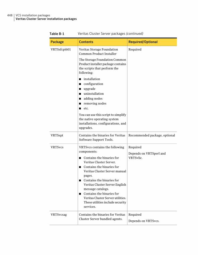
Table B-1 Veritas Cluster Server packages (continued)
Required/OptionalContentsPackage
RequiredVeritas Storage FoundationCommon Product Installer
The Storage Foundation CommonProduct installer package containsthe scripts that perform thefollowing:
■ installation
■ configuration
■ upgrade
■ uninstallation
■ adding nodes
■ removing nodes
■ etc.
You can use this script to simplifythe native operating systeminstallations, configurations, andupgrades.
VRTSsfcpi601
Recommended package, optionalContains the binaries for VeritasSoftware Support Tools.
VRTSspt
Required
Depends on VRTSperl andVRTSvlic.
VRTSvcs contains the followingcomponents:
■ Contains the binaries forVeritas Cluster Server.
■ Contains the binaries forVeritas Cluster Server manualpages.
■ Contains the binaries forVeritas Cluster Server Englishmessage catalogs.
■ Contains the binaries forVeritas Cluster Server utilities.These utilities include securityservices.
VRTSvcs
Required
Depends on VRTSvcs.
Contains the binaries for VeritasCluster Server bundled agents.
VRTSvcsag
VCS installation packagesVeritas Cluster Server installation packages
448
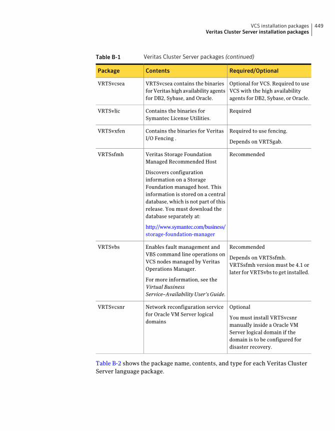
Table B-1 Veritas Cluster Server packages (continued)
Required/OptionalContentsPackage
Optional for VCS. Required to useVCS with the high availabilityagents for DB2, Sybase, or Oracle.
VRTSvcsea contains the binariesfor Veritas high availability agentsfor DB2, Sybase, and Oracle.
VRTSvcsea
RequiredContains the binaries forSymantec License Utilities.
VRTSvlic
Required to use fencing.
Depends on VRTSgab.
Contains the binaries for VeritasI/O Fencing .
VRTSvxfen
RecommendedVeritas Storage FoundationManaged Recommended Host
Discovers configurationinformation on a StorageFoundation managed host. Thisinformation is stored on a centraldatabase, which is not part of thisrelease. You must download thedatabase separately at:
http://www.symantec.com/business/storage-foundation-manager
VRTSsfmh
Recommended
Depends on VRTSsfmh.VRTSsfmh version must be 4.1 orlater for VRTSvbs to get installed.
Enables fault management andVBS command line operations onVCS nodes managed by VeritasOperations Manager.
For more information, see theVirtual BusinessService–Availability User’s Guide.
VRTSvbs
Optional
You must install VRTSvcsnrmanually inside a Oracle VMServer logical domain if thedomain is to be configured fordisaster recovery.
Network reconfiguration servicefor Oracle VM Server logicaldomains
VRTSvcsnr
Table B-2 shows the package name, contents, and type for each Veritas ClusterServer language package.
449VCS installation packagesVeritas Cluster Server installation packages
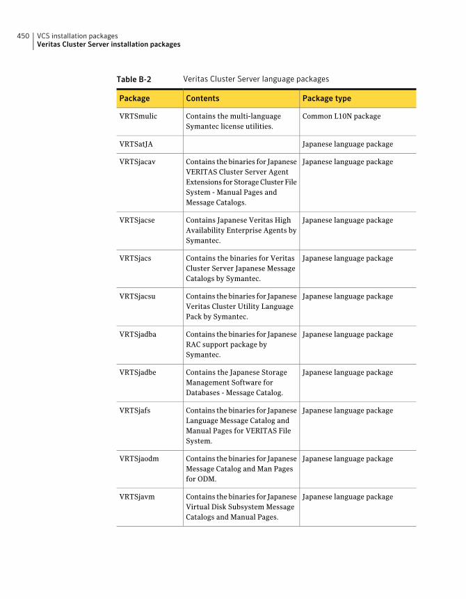
Table B-2 Veritas Cluster Server language packages
Package typeContentsPackage
Common L10N packageContains the multi-languageSymantec license utilities.
VRTSmulic
Japanese language packageVRTSatJA
Japanese language packageContains the binaries for JapaneseVERITAS Cluster Server AgentExtensions for Storage Cluster FileSystem - Manual Pages andMessage Catalogs.
VRTSjacav
Japanese language packageContains Japanese Veritas HighAvailability Enterprise Agents bySymantec.
VRTSjacse
Japanese language packageContains the binaries for VeritasCluster Server Japanese MessageCatalogs by Symantec.
VRTSjacs
Japanese language packageContains the binaries for JapaneseVeritas Cluster Utility LanguagePack by Symantec.
VRTSjacsu
Japanese language packageContains the binaries for JapaneseRAC support package bySymantec.
VRTSjadba
Japanese language packageContains the Japanese StorageManagement Software forDatabases - Message Catalog.
VRTSjadbe
Japanese language packageContains the binaries for JapaneseLanguage Message Catalog andManual Pages for VERITAS FileSystem.
VRTSjafs
Japanese language packageContains the binaries for JapaneseMessage Catalog and Man Pagesfor ODM.
VRTSjaodm
Japanese language packageContains the binaries for JapaneseVirtual Disk Subsystem MessageCatalogs and Manual Pages.
VRTSjavm
VCS installation packagesVeritas Cluster Server installation packages
450

Table B-2 Veritas Cluster Server language packages (continued)
Package typeContentsPackage
Chinese language packageContains the binaries for ChineseVirtual Disk Subsystem MessageCatalogs and Manual Pages.
VRTSzhvm
451VCS installation packagesVeritas Cluster Server installation packages

VCS installation packagesVeritas Cluster Server installation packages
452
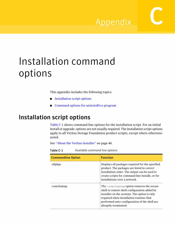
Installation commandoptions
This appendix includes the following topics:
■ Installation script options
■ Command options for uninstallvcs program
Installation script optionsTable C-1 shows command line options for the installation script. For an initialinstall or upgrade, options are not usually required. The installation script optionsapply to all Veritas Storage Foundation product scripts, except where otherwisenoted.
See “About the Veritas installer” on page 46.
Table C-1 Available command line options
FunctionCommandline Option
Displays all packages required for the specifiedproduct. The packages are listed in correctinstallation order. The output can be used tocreate scripts for command line installs, or forinstallations over a network.
-allpkgs
The -comcleanup option removes the secureshell or remote shell configuration added byinstaller on the systems. The option is onlyrequired when installation routines thatperformed auto-configuration of the shell areabruptly terminated.
-comcleanup
CAppendix
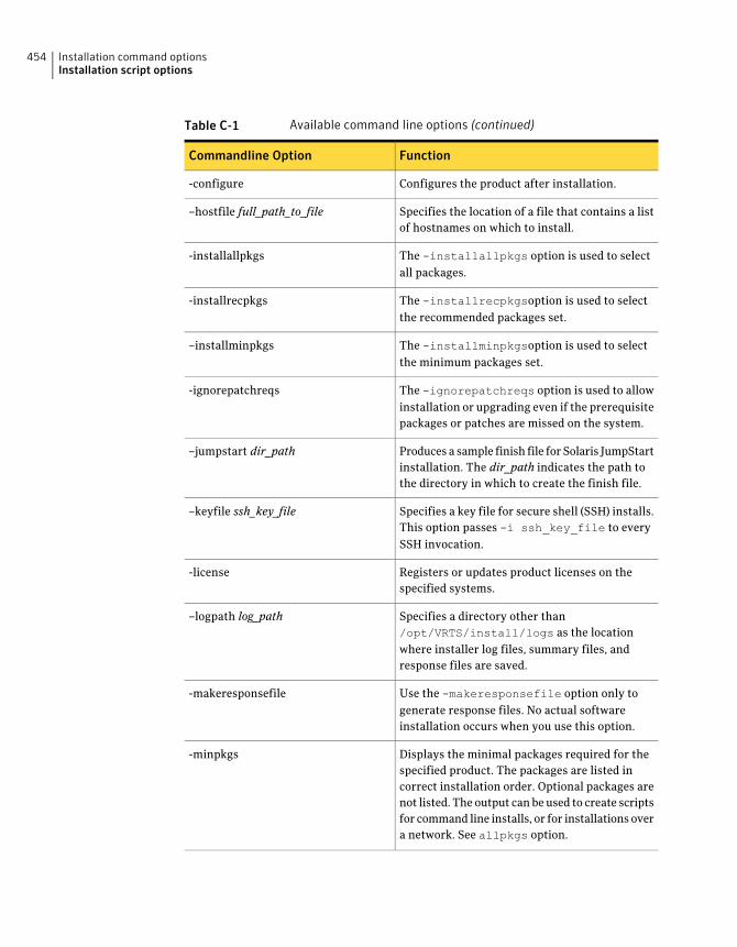
Table C-1 Available command line options (continued)
FunctionCommandline Option
Configures the product after installation.-configure
Specifies the location of a file that contains a listof hostnames on which to install.
–hostfile full_path_to_file
The -installallpkgs option is used to selectall packages.
-installallpkgs
The -installrecpkgsoption is used to selectthe recommended packages set.
-installrecpkgs
The -installminpkgsoption is used to selectthe minimum packages set.
–installminpkgs
The -ignorepatchreqs option is used to allowinstallation or upgrading even if the prerequisitepackages or patches are missed on the system.
-ignorepatchreqs
Produces a sample finish file for Solaris JumpStartinstallation. The dir_path indicates the path tothe directory in which to create the finish file.
–jumpstart dir_path
Specifies a key file for secure shell (SSH) installs.This option passes -i ssh_key_file to everySSH invocation.
–keyfile ssh_key_file
Registers or updates product licenses on thespecified systems.
-license
Specifies a directory other than/opt/VRTS/install/logs as the locationwhere installer log files, summary files, andresponse files are saved.
–logpath log_path
Use the -makeresponsefile option only togenerate response files. No actual softwareinstallation occurs when you use this option.
-makeresponsefile
Displays the minimal packages required for thespecified product. The packages are listed incorrect installation order. Optional packages arenot listed. The output can be used to create scriptsfor command line installs, or for installations overa network. See allpkgs option.
-minpkgs
Installation command optionsInstallation script options
454
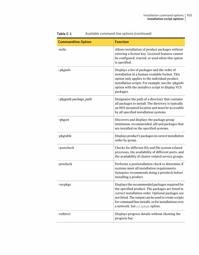
Table C-1 Available command line options (continued)
FunctionCommandline Option
Allows installation of product packages withoutentering a license key. Licensed features cannotbe configured, started, or used when this optionis specified.
-nolic
Displays a list of packages and the order ofinstallation in a human-readable format. Thisoption only applies to the individual productinstallation scripts. For example, use the -pkginfooption with the installvcs script to display VCSpackages.
–pkginfo
Designates the path of a directory that containsall packages to install. The directory is typicallyan NFS-mounted location and must be accessibleby all specified installation systems.
–pkgpath package_path
Discovers and displays the package group(minimum, recommended, all) and packages thatare installed on the specified systems.
–pkgset
Displays product's packages in correct installationorder by group.
-pkgtable
Checks for different HA and file system-relatedprocesses, the availability of different ports, andthe availability of cluster-related service groups.
–postcheck
Performs a preinstallation check to determine ifsystems meet all installation requirements.Symantec recommends doing a precheck beforeinstalling a product.
-precheck
Displays the recommended packages required forthe specified product. The packages are listed incorrect installation order. Optional packages arenot listed. The output can be used to create scriptsfor command line installs, or for installations overa network. See allpkgs option.
–recpkgs
Displays progress details without showing theprogress bar.
-redirect
455Installation command optionsInstallation script options
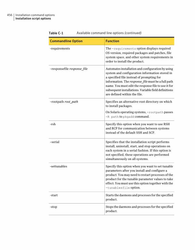
Table C-1 Available command line options (continued)
FunctionCommandline Option
The -requirements option displays requiredOS version, required packages and patches, filesystem space, and other system requirements inorder to install the product.
-requirements
Automates installation and configuration by usingsystem and configuration information stored ina specified file instead of prompting forinformation. The response_filemust be a full pathname. You must edit the response file to use it forsubsequent installations. Variable field definitionsare defined within the file.
–responsefile response_file
Specifies an alternative root directory on whichto install packages.
On Solaris operating systems,-rootpathpasses-R path to pkgadd command.
–rootpath root_path
Specify this option when you want to use RSHand RCP for communication between systemsinstead of the default SSH and SCP.
-rsh
Specifies that the installation script performsinstall, uninstall, start, and stop operations oneach system in a serial fashion. If this option isnot specified, these operations are performedsimultaneously on all systems.
–serial
Specify this option when you want to set tunableparameters after you install and configure aproduct. You may need to restart processes of theproduct for the tunable parameter values to takeeffect. You must use this option together with the-tunablesfile option.
-settunables
Starts the daemons and processes for the specifiedproduct.
-start
Stops the daemons and processes for the specifiedproduct.
-stop
Installation command optionsInstallation script options
456
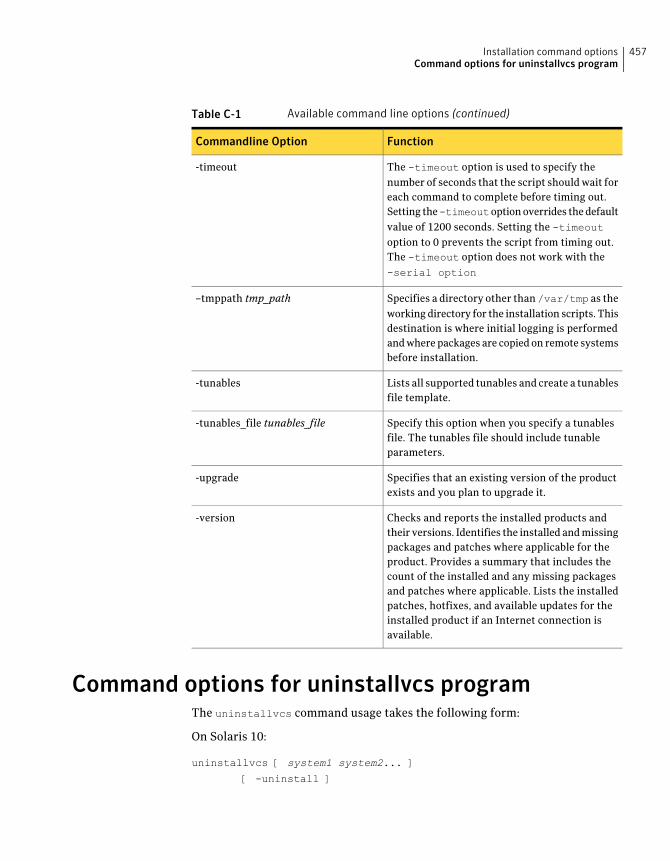
Table C-1 Available command line options (continued)
FunctionCommandline Option
The -timeout option is used to specify thenumber of seconds that the script should wait foreach command to complete before timing out.Setting the-timeoutoption overrides the defaultvalue of 1200 seconds. Setting the -timeoutoption to 0 prevents the script from timing out.The -timeout option does not work with the-serial option
-timeout
Specifies a directory other than/var/tmp as theworking directory for the installation scripts. Thisdestination is where initial logging is performedand where packages are copied on remote systemsbefore installation.
–tmppath tmp_path
Lists all supported tunables and create a tunablesfile template.
-tunables
Specify this option when you specify a tunablesfile. The tunables file should include tunableparameters.
-tunables_file tunables_file
Specifies that an existing version of the productexists and you plan to upgrade it.
-upgrade
Checks and reports the installed products andtheir versions. Identifies the installed and missingpackages and patches where applicable for theproduct. Provides a summary that includes thecount of the installed and any missing packagesand patches where applicable. Lists the installedpatches, hotfixes, and available updates for theinstalled product if an Internet connection isavailable.
-version
Command options for uninstallvcs programThe uninstallvcs command usage takes the following form:
On Solaris 10:
uninstallvcs [ system1 system2... ]
[ -uninstall ]
457Installation command optionsCommand options for uninstallvcs program
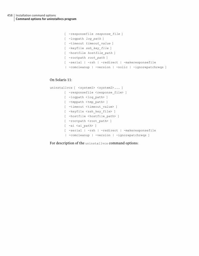
[ -responsefile response_file ]
[ -logpath log_path ]
[ -timeout timeout_value ]
[ -keyfile ssh_key_file ]
[ -hostfile hostfile_path ]
[ -rootpath root_path ]
[ -serial | -rsh | -redirect | -makeresponsefile
| -comcleanup | -version | -nolic | -ignorepatchreqs ]
On Solaris 11:
uninstallvcs [ <system1> <system2>... ]
[ -responsefile <response_file> ]
[ -logpath <log_path> ]
[ -tmppath <tmp_path> ]
[ -timeout <timeout_value> ]
[ -keyfile <ssh_key_file> ]
[ -hostfile <hostfile_path> ]
[ -rootpath <root_path> ]
[ -ai <ai_path> ]
[ -serial | -rsh | -redirect | -makeresponsefile
| -comcleanup | -version | -ignorepatchreqs ]
For description of the uninstallvcs command options:
Installation command optionsCommand options for uninstallvcs program
458
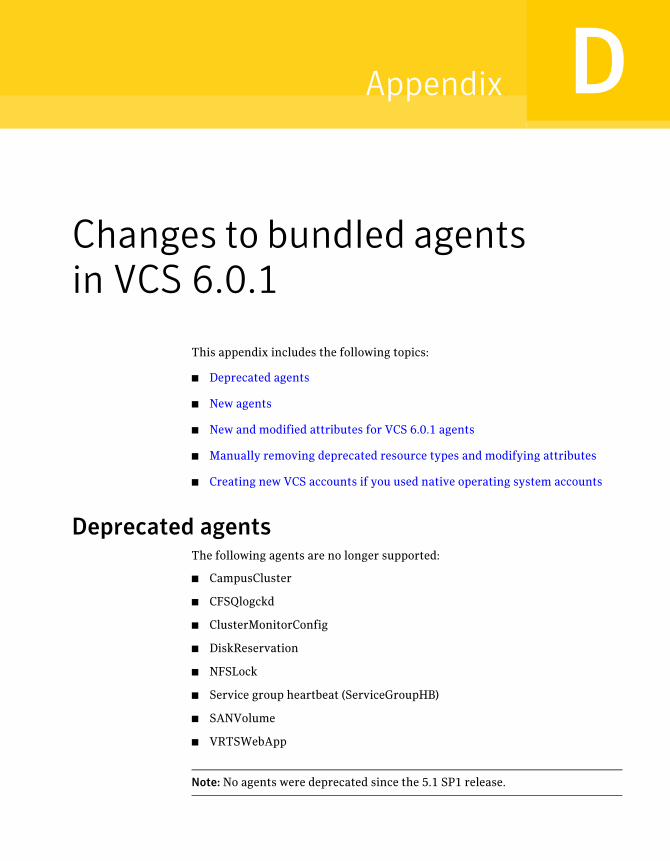
Changes to bundled agentsin VCS 6.0.1
This appendix includes the following topics:
■ Deprecated agents
■ New agents
■ New and modified attributes for VCS 6.0.1 agents
■ Manually removing deprecated resource types and modifying attributes
■ Creating new VCS accounts if you used native operating system accounts
Deprecated agentsThe following agents are no longer supported:
■ CampusCluster
■ CFSQlogckd
■ ClusterMonitorConfig
■ DiskReservation
■ NFSLock
■ Service group heartbeat (ServiceGroupHB)
■ SANVolume
■ VRTSWebApp
Note: No agents were deprecated since the 5.1 SP1 release.
DAppendix
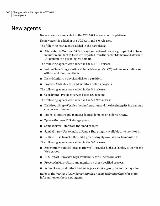
New agentsNo new agents were added in the VCS 6.0.1 release on this platform.
No new agent is added in the VCS 6.0.1 and 6.0 releases.
The following new agent is added in the 6.0 release:
■ AlternateIO—Monitors VCS storage and network service groups that in turnmonitor redundant I/O services exported from the control domain and alternateI/O domain to a guest logical domain.
The following agents were added in the 5.1 SP1 release:
■ VolumeSet—Brings Veritas Volume Manager (VxVM) volume sets online andoffline, and monitors them.
■ Disk—Monitors a physical disk or a partition.
■ Project—Adds, deletes, and monitors Solaris projects.
The following agents were added in the 5.1 release:
■ CoordPoint—Provides server-based I/O fencing.
The following agents were added in the 5.0 MP3 release:
■ DiskGroupSnap—Verifies the configuration and the data integrity in a campuscluster environment.
■ LDom—Monitors and manages logical domains on Solaris SPARC.
■ Zpool—Monitors ZFS storage pools.
■ SambaServer—Monitors the smbd process.
■ SambaShare—Use to make a Samba Share highly available or to monitor it.
■ NetBios—Use to make the nmbd process highly available or to monitor it.
The following agents were added in the 5.0 release:
■ Apache (now bundled on all platforms)—Provides high availability to an ApacheWeb server.
■ NFSRestart—Provides high availability for NFS record locks.
■ ProcessOnOnly—Starts and monitors a user-specified process.
■ RemoteGroup—Monitors and manages a service group on another system.
Refer to the Veritas Cluster Server Bundled Agents Reference Guide for moreinformation on these new agents.
Changes to bundled agents in VCS 6.0.1New agents
460
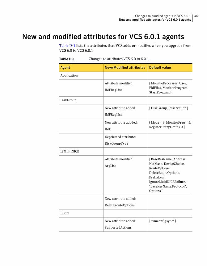
New and modified attributes for VCS 6.0.1 agentsTable D-1 lists the attributes that VCS adds or modifies when you upgrade fromVCS 6.0 to VCS 6.0.1
Table D-1 Changes to attributes VCS 6.0 to 6.0.1
Default valueNew/Modified attributesAgent
Application
{ MonitorProcesses, User,PidFiles, MonitorProgram,StartProgram }
Attribute modified:
IMFRegList
DiskGroup
{ DiskGroup, Reservation }New attribute added:
IMFRegList
{ Mode = 3, MonitorFreq = 5,RegisterRetryLimit = 3 }
New attribute addded:
IMF
Depricated attribute:
DiskGroupType
IPMultiNICB
{ BaseResName, Address,NetMask, DeviceChoice,RouteOptions,DeleteRouteOptions,PrefixLen,IgnoreMultiNICBFailure,"BaseResName:Protocol",Options }
Attribute modified:
ArgList
New attribute added:
DeleteRouteOptions
LDom
{ "vmconfigsync" }New attribute added:
SupportedActions
461Changes to bundled agents in VCS 6.0.1New and modified attributes for VCS 6.0.1 agents
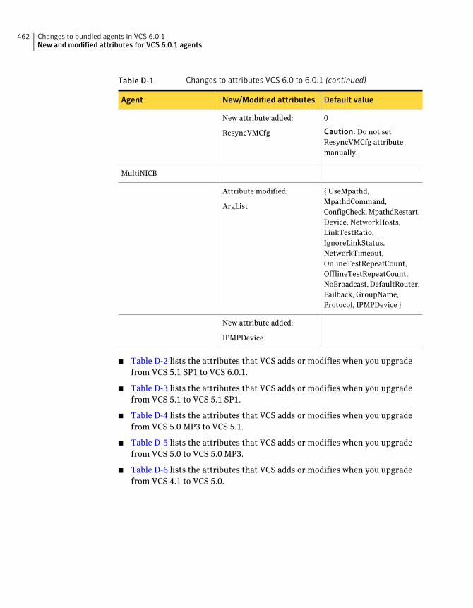
Table D-1 Changes to attributes VCS 6.0 to 6.0.1 (continued)
Default valueNew/Modified attributesAgent
0
Caution: Do not setResyncVMCfg attributemanually.
New attribute added:
ResyncVMCfg
MultiNICB
{ UseMpathd,MpathdCommand,ConfigCheck, MpathdRestart,Device, NetworkHosts,LinkTestRatio,IgnoreLinkStatus,NetworkTimeout,OnlineTestRepeatCount,OfflineTestRepeatCount,NoBroadcast, DefaultRouter,Failback, GroupName,Protocol, IPMPDevice }
Attribute modified:
ArgList
New attribute added:
IPMPDevice
■ Table D-2 lists the attributes that VCS adds or modifies when you upgradefrom VCS 5.1 SP1 to VCS 6.0.1.
■ Table D-3 lists the attributes that VCS adds or modifies when you upgradefrom VCS 5.1 to VCS 5.1 SP1.
■ Table D-4 lists the attributes that VCS adds or modifies when you upgradefrom VCS 5.0 MP3 to VCS 5.1.
■ Table D-5 lists the attributes that VCS adds or modifies when you upgradefrom VCS 5.0 to VCS 5.0 MP3.
■ Table D-6 lists the attributes that VCS adds or modifies when you upgradefrom VCS 4.1 to VCS 5.0.
Changes to bundled agents in VCS 6.0.1New and modified attributes for VCS 6.0.1 agents
462
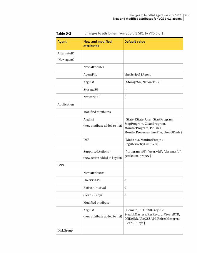
Table D-2 Changes to attributes from VCS 5.1 SP1 to VCS 6.0.1
Default valueNew and modifiedattributes
Agent
AlternateIO
(New agent)
New attributes
bin/Script51AgentAgentFile
{ StorageSG, NetworkSG }ArgList
{}StorageSG
{}NetworkSG
Application
Modified attributes
{ State, IState, User, StartProgram,StopProgram, CleanProgram,MonitorProgram, PidFiles,MonitorProcesses, EnvFile, UseSUDash }
ArgList
(new attribute added to list)
{ Mode = 3, MonitorFreq = 1,RegisterRetryLimit = 3 }
IMF
{ "program.vfd", "user.vfd", "cksum.vfd",getcksum, propcv }
SupportedActions
(new action added to keylist)
DNS
New attributes
0UseGSSAPI
0RefreshInterval
0CleanRRKeys
Modified attribute
{ Domain, TTL, TSIGKeyFile,StealthMasters, ResRecord, CreatePTR,OffDelRR, UseGSSAPI, RefreshInterval,CleanRRKeys }
ArgList
(new attribute added to list)
DiskGroup
463Changes to bundled agents in VCS 6.0.1New and modified attributes for VCS 6.0.1 agents
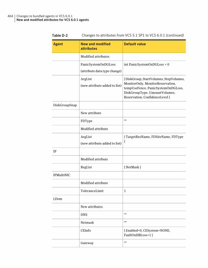
Table D-2 Changes to attributes from VCS 5.1 SP1 to VCS 6.0.1 (continued)
Default valueNew and modifiedattributes
Agent
Modified attributes
int PanicSystemOnDGLoss = 0PanicSystemOnDGLoss
(attribute data type change)
{ DiskGroup, StartVolumes, StopVolumes,MonitorOnly, MonitorReservation,tempUseFence, PanicSystemOnDGLoss,DiskGroupType, UmountVolumes,Reservation, ConfidenceLevel }
ArgList
(new attribute added to list)
DiskGroupSnap
New attribute
""FDType
Modified attribute
{ TargetResName, FDSiteName, FDType}
ArgList
(new attribute added to list)
IP
Modified attribute
{ NetMask }RegList
IPMultiNIC
Modified attribute
1ToleranceLimit
LDom
New attributes
""DNS
""Netmask
{ Enabled=0, CESystem=NONE,FaultOnHBLoss=1 }
CEInfo
""Gateway
Changes to bundled agents in VCS 6.0.1New and modified attributes for VCS 6.0.1 agents
464
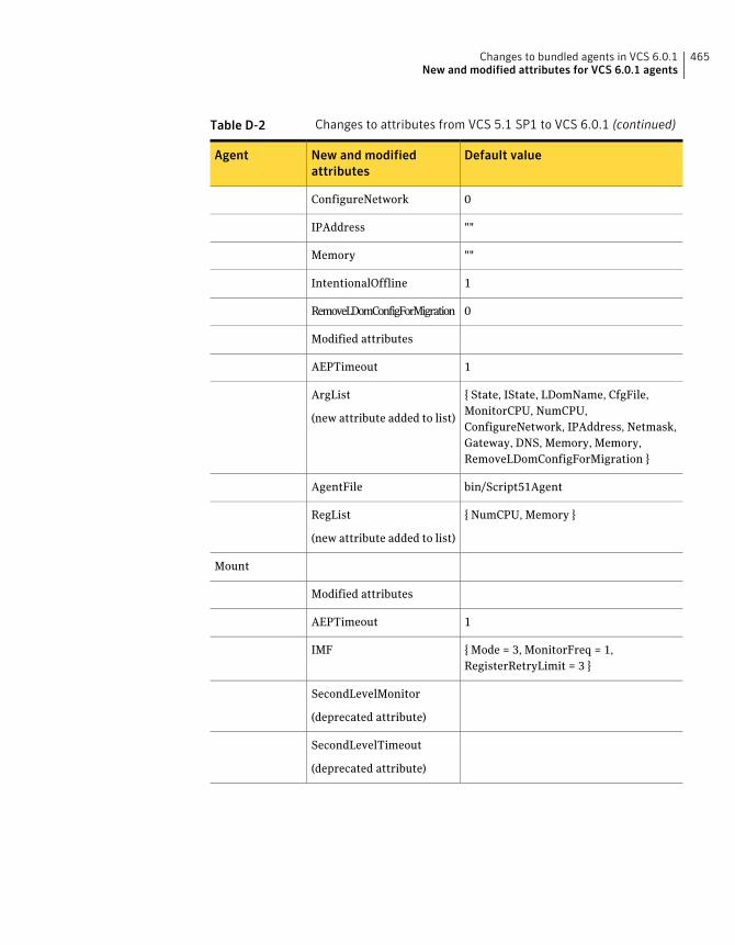
Table D-2 Changes to attributes from VCS 5.1 SP1 to VCS 6.0.1 (continued)
Default valueNew and modifiedattributes
Agent
0ConfigureNetwork
""IPAddress
""Memory
1IntentionalOffline
0RemoveLDomConfigForMigration
Modified attributes
1AEPTimeout
{ State, IState, LDomName, CfgFile,MonitorCPU, NumCPU,ConfigureNetwork, IPAddress, Netmask,Gateway, DNS, Memory, Memory,RemoveLDomConfigForMigration }
ArgList
(new attribute added to list)
bin/Script51AgentAgentFile
{ NumCPU, Memory }RegList
(new attribute added to list)
Mount
Modified attributes
1AEPTimeout
{ Mode = 3, MonitorFreq = 1,RegisterRetryLimit = 3 }
IMF
SecondLevelMonitor
(deprecated attribute)
SecondLevelTimeout
(deprecated attribute)
465Changes to bundled agents in VCS 6.0.1New and modified attributes for VCS 6.0.1 agents
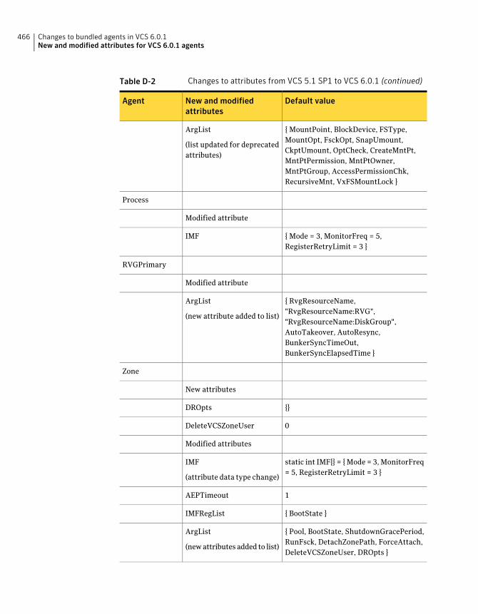
Table D-2 Changes to attributes from VCS 5.1 SP1 to VCS 6.0.1 (continued)
Default valueNew and modifiedattributes
Agent
{ MountPoint, BlockDevice, FSType,MountOpt, FsckOpt, SnapUmount,CkptUmount, OptCheck, CreateMntPt,MntPtPermission, MntPtOwner,MntPtGroup, AccessPermissionChk,RecursiveMnt, VxFSMountLock }
ArgList
(list updated for deprecatedattributes)
Process
Modified attribute
{ Mode = 3, MonitorFreq = 5,RegisterRetryLimit = 3 }
IMF
RVGPrimary
Modified attribute
{ RvgResourceName,"RvgResourceName:RVG","RvgResourceName:DiskGroup",AutoTakeover, AutoResync,BunkerSyncTimeOut,BunkerSyncElapsedTime }
ArgList
(new attribute added to list)
Zone
New attributes
{}DROpts
0DeleteVCSZoneUser
Modified attributes
static int IMF{} = { Mode = 3, MonitorFreq= 5, RegisterRetryLimit = 3 }
IMF
(attribute data type change)
1AEPTimeout
{ BootState }IMFRegList
{ Pool, BootState, ShutdownGracePeriod,RunFsck, DetachZonePath, ForceAttach,DeleteVCSZoneUser, DROpts }
ArgList
(new attributes added to list)
Changes to bundled agents in VCS 6.0.1New and modified attributes for VCS 6.0.1 agents
466
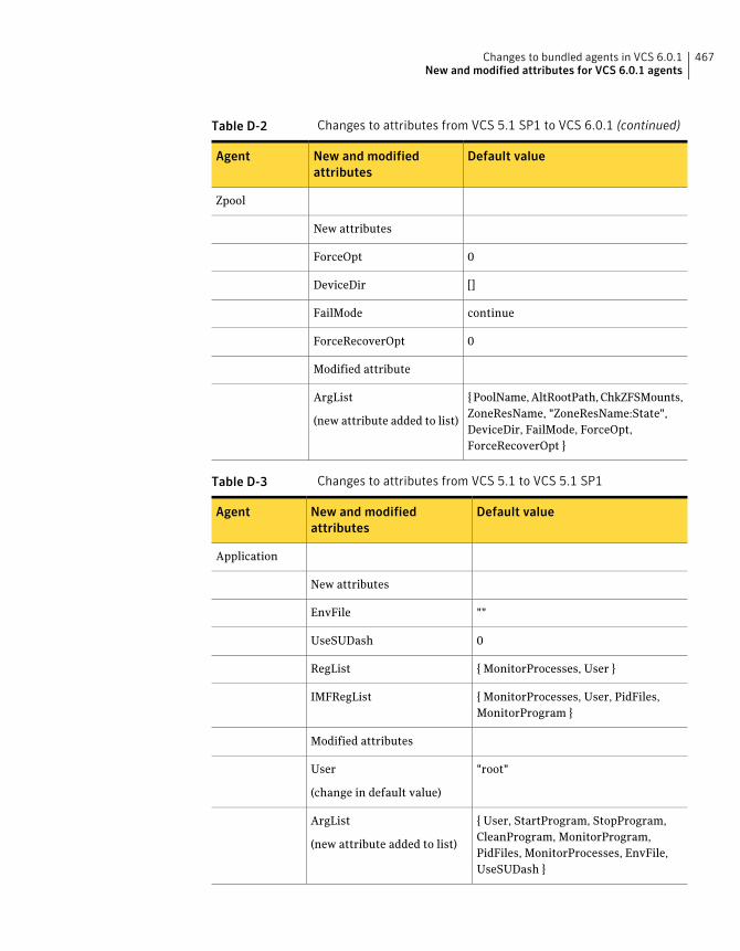
Table D-2 Changes to attributes from VCS 5.1 SP1 to VCS 6.0.1 (continued)
Default valueNew and modifiedattributes
Agent
Zpool
New attributes
0ForceOpt
[]DeviceDir
continueFailMode
0ForceRecoverOpt
Modified attribute
{ PoolName, AltRootPath, ChkZFSMounts,ZoneResName, "ZoneResName:State",DeviceDir, FailMode, ForceOpt,ForceRecoverOpt }
ArgList
(new attribute added to list)
Table D-3 Changes to attributes from VCS 5.1 to VCS 5.1 SP1
Default valueNew and modifiedattributes
Agent
Application
New attributes
""EnvFile
0UseSUDash
{ MonitorProcesses, User }RegList
{ MonitorProcesses, User, PidFiles,MonitorProgram }
IMFRegList
Modified attributes
"root"User
(change in default value)
{ User, StartProgram, StopProgram,CleanProgram, MonitorProgram,PidFiles, MonitorProcesses, EnvFile,UseSUDash }
ArgList
(new attribute added to list)
467Changes to bundled agents in VCS 6.0.1New and modified attributes for VCS 6.0.1 agents
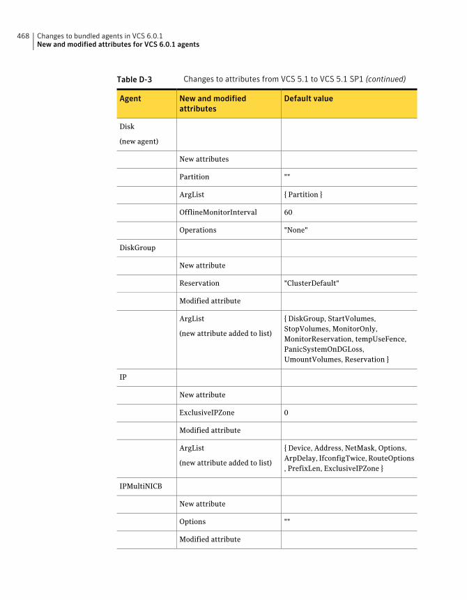
Table D-3 Changes to attributes from VCS 5.1 to VCS 5.1 SP1 (continued)
Default valueNew and modifiedattributes
Agent
Disk
(new agent)
New attributes
""Partition
{ Partition }ArgList
60OfflineMonitorInterval
"None"Operations
DiskGroup
New attribute
"ClusterDefault"Reservation
Modified attribute
{ DiskGroup, StartVolumes,StopVolumes, MonitorOnly,MonitorReservation, tempUseFence,PanicSystemOnDGLoss,UmountVolumes, Reservation }
ArgList
(new attribute added to list)
IP
New attribute
0ExclusiveIPZone
Modified attribute
{ Device, Address, NetMask, Options,ArpDelay, IfconfigTwice, RouteOptions, PrefixLen, ExclusiveIPZone }
ArgList
(new attribute added to list)
IPMultiNICB
New attribute
""Options
Modified attribute
Changes to bundled agents in VCS 6.0.1New and modified attributes for VCS 6.0.1 agents
468
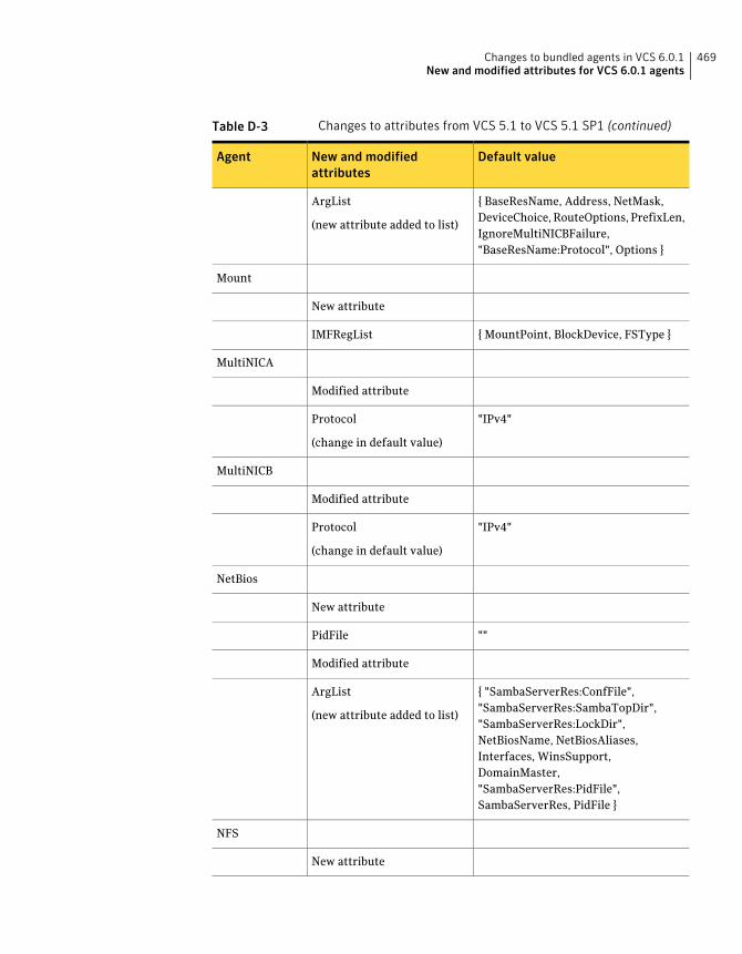
Table D-3 Changes to attributes from VCS 5.1 to VCS 5.1 SP1 (continued)
Default valueNew and modifiedattributes
Agent
{ BaseResName, Address, NetMask,DeviceChoice, RouteOptions, PrefixLen,IgnoreMultiNICBFailure,"BaseResName:Protocol", Options }
ArgList
(new attribute added to list)
Mount
New attribute
{ MountPoint, BlockDevice, FSType }IMFRegList
MultiNICA
Modified attribute
"IPv4"Protocol
(change in default value)
MultiNICB
Modified attribute
"IPv4"Protocol
(change in default value)
NetBios
New attribute
""PidFile
Modified attribute
{ "SambaServerRes:ConfFile","SambaServerRes:SambaTopDir","SambaServerRes:LockDir",NetBiosName, NetBiosAliases,Interfaces, WinsSupport,DomainMaster,"SambaServerRes:PidFile",SambaServerRes, PidFile }
ArgList
(new attribute added to list)
NFS
New attribute
469Changes to bundled agents in VCS 6.0.1New and modified attributes for VCS 6.0.1 agents
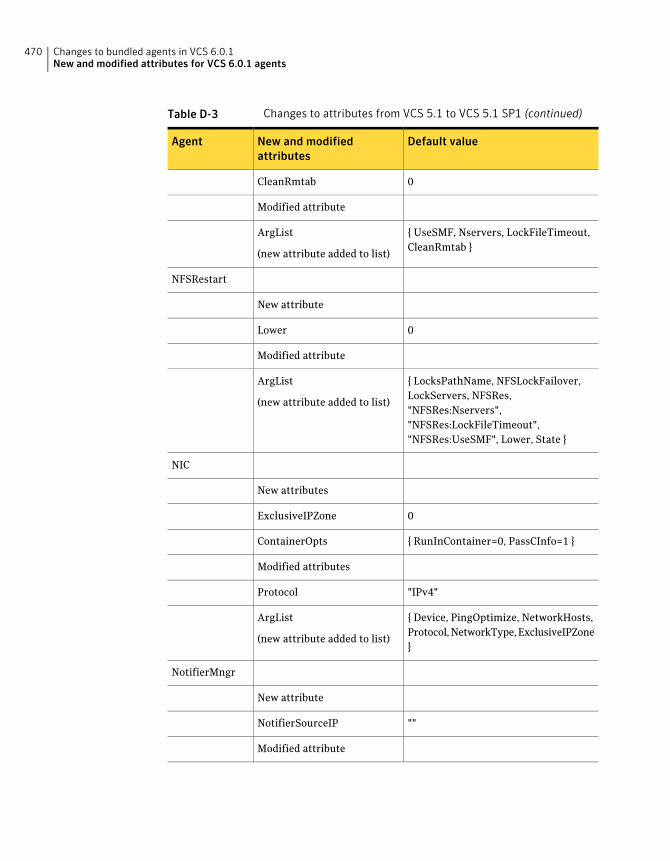
Table D-3 Changes to attributes from VCS 5.1 to VCS 5.1 SP1 (continued)
Default valueNew and modifiedattributes
Agent
0CleanRmtab
Modified attribute
{ UseSMF, Nservers, LockFileTimeout,CleanRmtab }
ArgList
(new attribute added to list)
NFSRestart
New attribute
0Lower
Modified attribute
{ LocksPathName, NFSLockFailover,LockServers, NFSRes,"NFSRes:Nservers","NFSRes:LockFileTimeout","NFSRes:UseSMF", Lower, State }
ArgList
(new attribute added to list)
NIC
New attributes
0ExclusiveIPZone
{ RunInContainer=0, PassCInfo=1 }ContainerOpts
Modified attributes
"IPv4"Protocol
{ Device, PingOptimize, NetworkHosts,Protocol, NetworkType, ExclusiveIPZone}
ArgList
(new attribute added to list)
NotifierMngr
New attribute
""NotifierSourceIP
Modified attribute
Changes to bundled agents in VCS 6.0.1New and modified attributes for VCS 6.0.1 agents
470
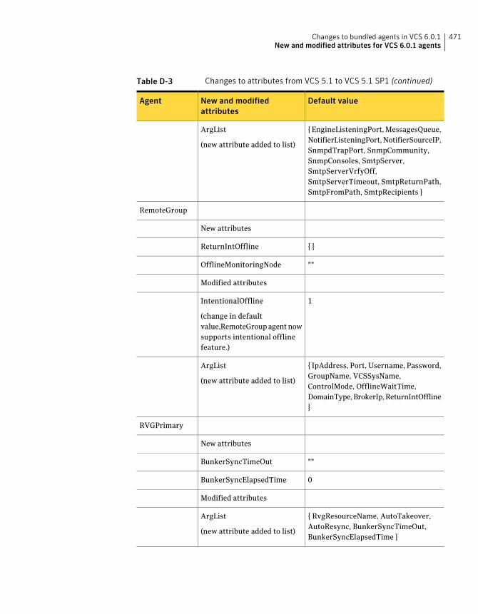
Table D-3 Changes to attributes from VCS 5.1 to VCS 5.1 SP1 (continued)
Default valueNew and modifiedattributes
Agent
{ EngineListeningPort, MessagesQueue,NotifierListeningPort, NotifierSourceIP,SnmpdTrapPort, SnmpCommunity,SnmpConsoles, SmtpServer,SmtpServerVrfyOff,SmtpServerTimeout, SmtpReturnPath,SmtpFromPath, SmtpRecipients }
ArgList
(new attribute added to list)
RemoteGroup
New attributes
{ }ReturnIntOffline
""OfflineMonitoringNode
Modified attributes
1IntentionalOffline
(change in defaultvalue,RemoteGroup agent nowsupports intentional offlinefeature.)
{ IpAddress, Port, Username, Password,GroupName, VCSSysName,ControlMode, OfflineWaitTime,DomainType, BrokerIp, ReturnIntOffline}
ArgList
(new attribute added to list)
RVGPrimary
New attributes
""BunkerSyncTimeOut
0BunkerSyncElapsedTime
Modified attributes
{ RvgResourceName, AutoTakeover,AutoResync, BunkerSyncTimeOut,BunkerSyncElapsedTime }
ArgList
(new attribute added to list)
471Changes to bundled agents in VCS 6.0.1New and modified attributes for VCS 6.0.1 agents
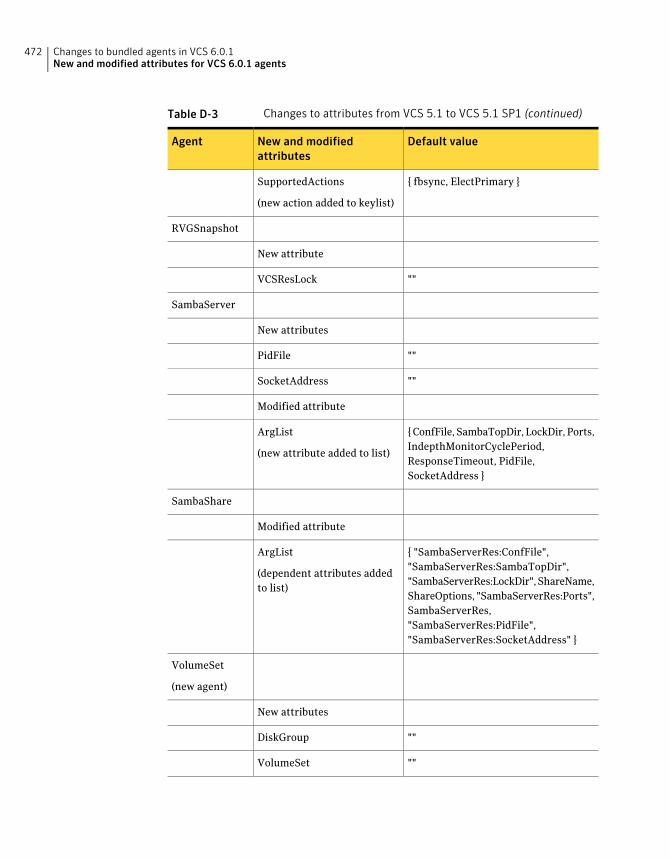
Table D-3 Changes to attributes from VCS 5.1 to VCS 5.1 SP1 (continued)
Default valueNew and modifiedattributes
Agent
{ fbsync, ElectPrimary }SupportedActions
(new action added to keylist)
RVGSnapshot
New attribute
""VCSResLock
SambaServer
New attributes
""PidFile
""SocketAddress
Modified attribute
{ ConfFile, SambaTopDir, LockDir, Ports,IndepthMonitorCyclePeriod,ResponseTimeout, PidFile,SocketAddress }
ArgList
(new attribute added to list)
SambaShare
Modified attribute
{ "SambaServerRes:ConfFile","SambaServerRes:SambaTopDir","SambaServerRes:LockDir", ShareName,ShareOptions, "SambaServerRes:Ports",SambaServerRes,"SambaServerRes:PidFile","SambaServerRes:SocketAddress" }
ArgList
(dependent attributes addedto list)
VolumeSet
(new agent)
New attributes
""DiskGroup
""VolumeSet
Changes to bundled agents in VCS 6.0.1New and modified attributes for VCS 6.0.1 agents
472
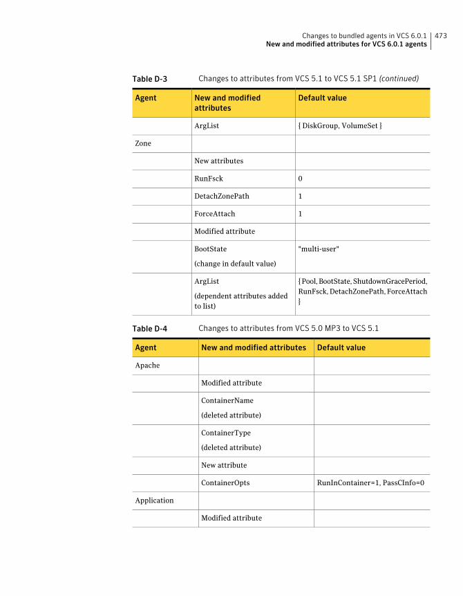
Table D-3 Changes to attributes from VCS 5.1 to VCS 5.1 SP1 (continued)
Default valueNew and modifiedattributes
Agent
{ DiskGroup, VolumeSet }ArgList
Zone
New attributes
0RunFsck
1DetachZonePath
1ForceAttach
Modified attribute
"multi-user"BootState
(change in default value)
{ Pool, BootState, ShutdownGracePeriod,RunFsck, DetachZonePath, ForceAttach}
ArgList
(dependent attributes addedto list)
Table D-4 Changes to attributes from VCS 5.0 MP3 to VCS 5.1
Default valueNew and modified attributesAgent
Apache
Modified attribute
ContainerName
(deleted attribute)
ContainerType
(deleted attribute)
New attribute
RunInContainer=1, PassCInfo=0ContainerOpts
Application
Modified attribute
473Changes to bundled agents in VCS 6.0.1New and modified attributes for VCS 6.0.1 agents
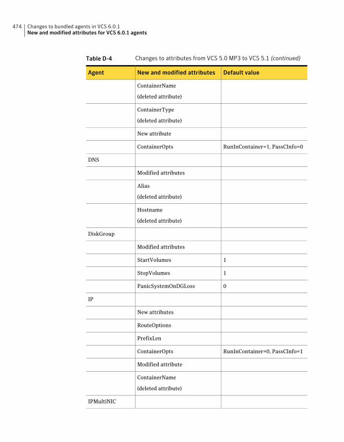
Table D-4 Changes to attributes from VCS 5.0 MP3 to VCS 5.1 (continued)
Default valueNew and modified attributesAgent
ContainerName
(deleted attribute)
ContainerType
(deleted attribute)
New attribute
RunInContainer=1, PassCInfo=0ContainerOpts
DNS
Modified attributes
Alias
(deleted attribute)
Hostname
(deleted attribute)
DiskGroup
Modified attributes
1StartVolumes
1StopVolumes
0PanicSystemOnDGLoss
IP
New attributes
RouteOptions
PrefixLen
RunInContainer=0, PassCInfo=1ContainerOpts
Modified attribute
ContainerName
(deleted attribute)
IPMultiNIC
Changes to bundled agents in VCS 6.0.1New and modified attributes for VCS 6.0.1 agents
474
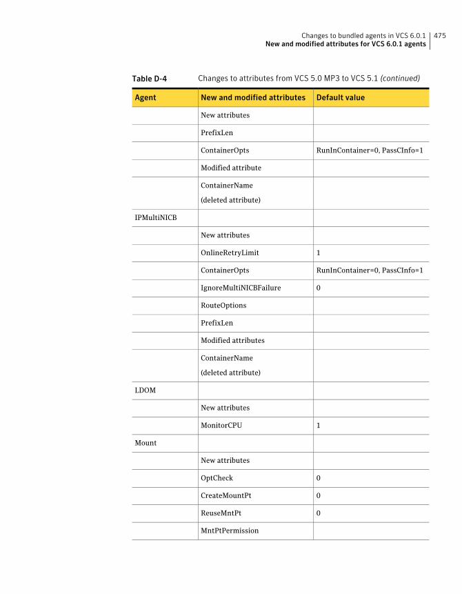
Table D-4 Changes to attributes from VCS 5.0 MP3 to VCS 5.1 (continued)
Default valueNew and modified attributesAgent
New attributes
PrefixLen
RunInContainer=0, PassCInfo=1ContainerOpts
Modified attribute
ContainerName
(deleted attribute)
IPMultiNICB
New attributes
1OnlineRetryLimit
RunInContainer=0, PassCInfo=1ContainerOpts
0IgnoreMultiNICBFailure
RouteOptions
PrefixLen
Modified attributes
ContainerName
(deleted attribute)
LDOM
New attributes
1MonitorCPU
Mount
New attributes
0OptCheck
0CreateMountPt
0ReuseMntPt
MntPtPermission
475Changes to bundled agents in VCS 6.0.1New and modified attributes for VCS 6.0.1 agents
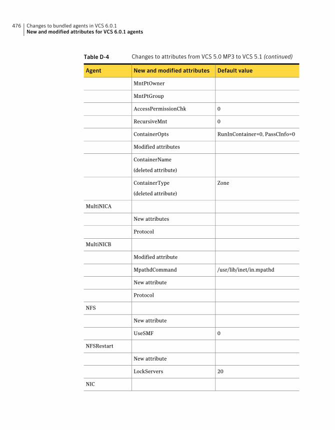
Table D-4 Changes to attributes from VCS 5.0 MP3 to VCS 5.1 (continued)
Default valueNew and modified attributesAgent
MntPtOwner
MntPtGroup
0AccessPermissionChk
0RecursiveMnt
RunInContainer=0, PassCInfo=0ContainerOpts
Modified attributes
ContainerName
(deleted attribute)
ZoneContainerType
(deleted attribute)
MultiNICA
New attributes
Protocol
MultiNICB
Modified attribute
/usr/lib/inet/in.mpathdMpathdCommand
New attribute
Protocol
NFS
New attribute
0UseSMF
NFSRestart
New attribute
20LockServers
NIC
Changes to bundled agents in VCS 6.0.1New and modified attributes for VCS 6.0.1 agents
476
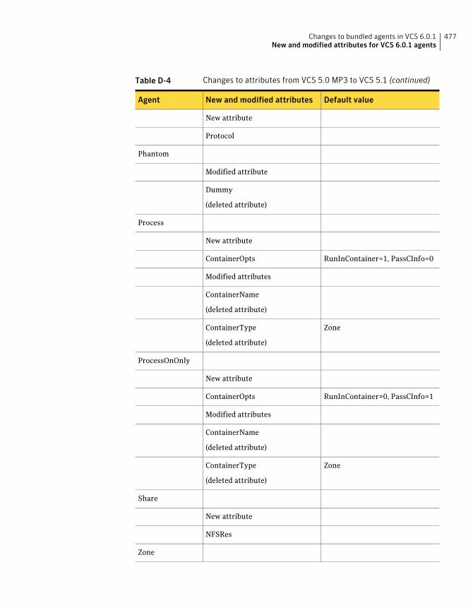
Table D-4 Changes to attributes from VCS 5.0 MP3 to VCS 5.1 (continued)
Default valueNew and modified attributesAgent
New attribute
Protocol
Phantom
Modified attribute
Dummy
(deleted attribute)
Process
New attribute
RunInContainer=1, PassCInfo=0ContainerOpts
Modified attributes
ContainerName
(deleted attribute)
ZoneContainerType
(deleted attribute)
ProcessOnOnly
New attribute
RunInContainer=0, PassCInfo=1ContainerOpts
Modified attributes
ContainerName
(deleted attribute)
ZoneContainerType
(deleted attribute)
Share
New attribute
NFSRes
Zone
477Changes to bundled agents in VCS 6.0.1New and modified attributes for VCS 6.0.1 agents
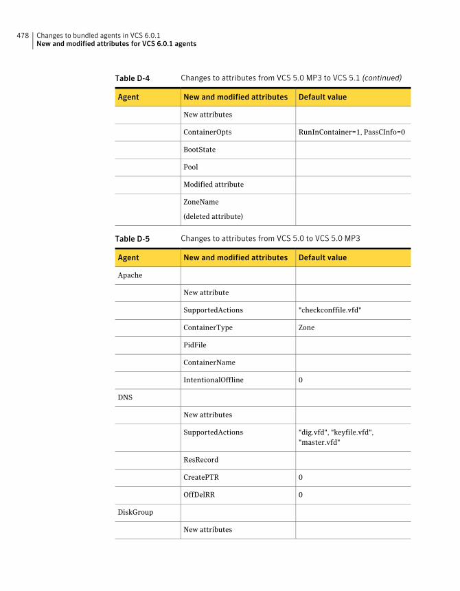
Table D-4 Changes to attributes from VCS 5.0 MP3 to VCS 5.1 (continued)
Default valueNew and modified attributesAgent
New attributes
RunInContainer=1, PassCInfo=0ContainerOpts
BootState
Pool
Modified attribute
ZoneName
(deleted attribute)
Table D-5 Changes to attributes from VCS 5.0 to VCS 5.0 MP3
Default valueNew and modified attributesAgent
Apache
New attribute
"checkconffile.vfd"SupportedActions
ZoneContainerType
PidFile
ContainerName
0IntentionalOffline
DNS
New attributes
"dig.vfd", "keyfile.vfd","master.vfd"
SupportedActions
ResRecord
0CreatePTR
0OffDelRR
DiskGroup
New attributes
Changes to bundled agents in VCS 6.0.1New and modified attributes for VCS 6.0.1 agents
478
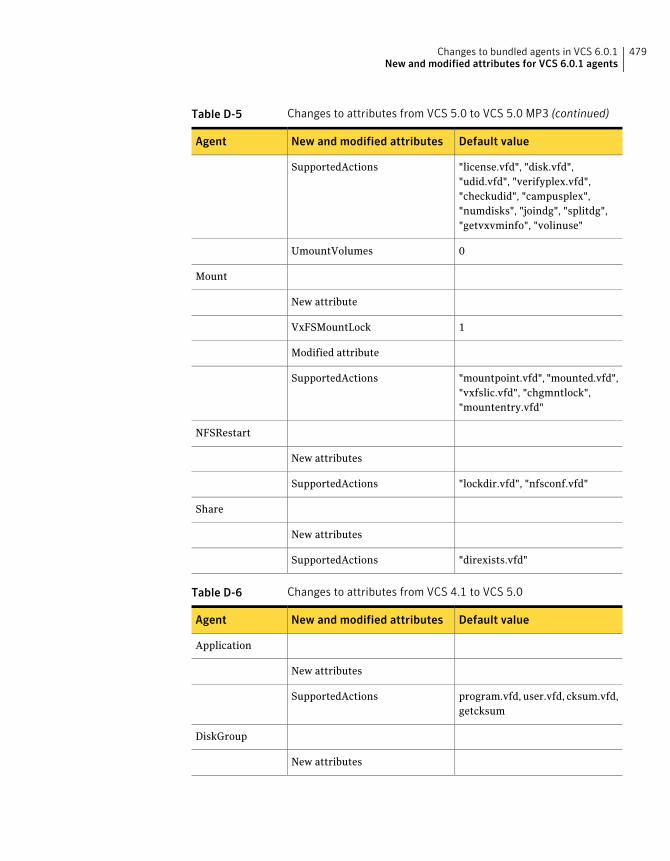
Table D-5 Changes to attributes from VCS 5.0 to VCS 5.0 MP3 (continued)
Default valueNew and modified attributesAgent
"license.vfd", "disk.vfd","udid.vfd", "verifyplex.vfd","checkudid", "campusplex","numdisks", "joindg", "splitdg","getvxvminfo", "volinuse"
SupportedActions
0UmountVolumes
Mount
New attribute
1VxFSMountLock
Modified attribute
"mountpoint.vfd", "mounted.vfd","vxfslic.vfd", "chgmntlock","mountentry.vfd"
SupportedActions
NFSRestart
New attributes
"lockdir.vfd", "nfsconf.vfd"SupportedActions
Share
New attributes
"direxists.vfd"SupportedActions
Table D-6 Changes to attributes from VCS 4.1 to VCS 5.0
Default valueNew and modified attributesAgent
Application
New attributes
program.vfd, user.vfd, cksum.vfd,getcksum
SupportedActions
DiskGroup
New attributes
479Changes to bundled agents in VCS 6.0.1New and modified attributes for VCS 6.0.1 agents
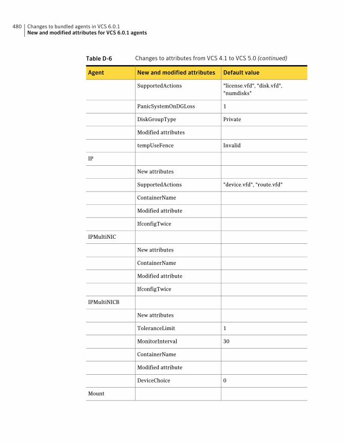
Table D-6 Changes to attributes from VCS 4.1 to VCS 5.0 (continued)
Default valueNew and modified attributesAgent
"license.vfd", "disk.vfd","numdisks"
SupportedActions
1PanicSystemOnDGLoss
PrivateDiskGroupType
Modified attributes
InvalidtempUseFence
IP
New attributes
"device.vfd", "route.vfd"SupportedActions
ContainerName
Modified attribute
IfconfigTwice
IPMultiNIC
New attributes
ContainerName
Modified attribute
IfconfigTwice
IPMultiNICB
New attributes
1ToleranceLimit
30MonitorInterval
ContainerName
Modified attribute
0DeviceChoice
Mount
Changes to bundled agents in VCS 6.0.1New and modified attributes for VCS 6.0.1 agents
480
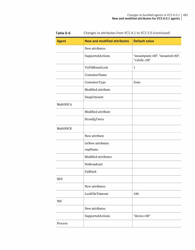
Table D-6 Changes to attributes from VCS 4.1 to VCS 5.0 (continued)
Default valueNew and modified attributesAgent
New attributes
"mountpoint.vfd", "mounted.vfd","vxfslic.vfd"
SupportedActions
1VxFSMountLock
ContainerName
ZoneContainerType
Modified attribute
SnapUmount
MultiNICA
Modified attribute
IfconfigTwice
MultiNICB
New attribute
GrNew attributes
oupName
Modified attributes
NoBroadcast
Failback
NFS
New attributes
180LockFileTimeout
NIC
New attributes
"device.vfd"SupportedActions
Process
481Changes to bundled agents in VCS 6.0.1New and modified attributes for VCS 6.0.1 agents
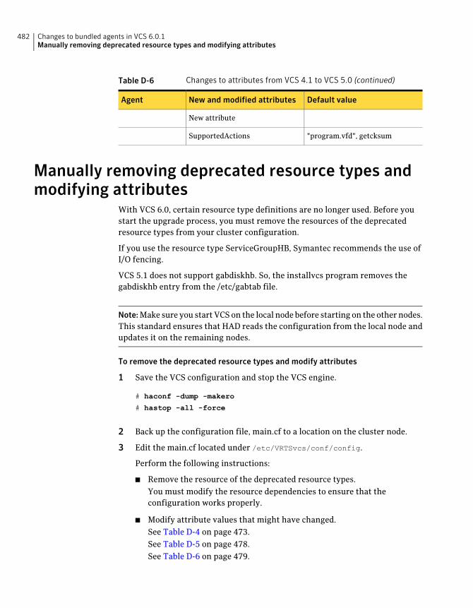
Table D-6 Changes to attributes from VCS 4.1 to VCS 5.0 (continued)
Default valueNew and modified attributesAgent
New attribute
"program.vfd", getcksumSupportedActions
Manually removing deprecated resource types andmodifying attributes
With VCS 6.0, certain resource type definitions are no longer used. Before youstart the upgrade process, you must remove the resources of the deprecatedresource types from your cluster configuration.
If you use the resource type ServiceGroupHB, Symantec recommends the use ofI/O fencing.
VCS 5.1 does not support gabdiskhb. So, the installvcs program removes thegabdiskhb entry from the /etc/gabtab file.
Note:Make sure you start VCS on the local node before starting on the other nodes.This standard ensures that HAD reads the configuration from the local node andupdates it on the remaining nodes.
To remove the deprecated resource types and modify attributes
1 Save the VCS configuration and stop the VCS engine.
# haconf -dump -makero
# hastop -all -force
2 Back up the configuration file, main.cf to a location on the cluster node.
3 Edit the main.cf located under /etc/VRTSvcs/conf/config.
Perform the following instructions:
■ Remove the resource of the deprecated resource types.You must modify the resource dependencies to ensure that theconfiguration works properly.
■ Modify attribute values that might have changed.See Table D-4 on page 473.See Table D-5 on page 478.See Table D-6 on page 479.
Changes to bundled agents in VCS 6.0.1Manually removing deprecated resource types and modifying attributes
482
■ Save the main.cf.
■ Reformat the main.cf file.
# hacf -cftocmd config
# hacf -cmdtocf config
4 Verify the configuration.
# cd /etc/VRTSvcs/conf/config
# hacf -verify config
5 Start VCS on the local node.
6 Start VCS on other nodes.
Creating new VCS accounts if you used nativeoperating system accounts
VCS has deprecated the AllowNativeCliUsers attribute. To use native OS accountswith VCS, use the halogin command. After you run the halogin command, VCSencrypts and stores your VCS credentials in your home directory for a specifictime period. After you run the halogin command, you need not authenticateyourself every time you run a VCS command. In secure clusters, the commandalso sets up a trust relationship and retrieves a certificate from an authenticationbroker.
See theVeritasCluster ServerAdministrator’sGuide for information on assigninguser privileges to OS user groups for clusters running in secure mode and clustersnot running in secure mode.
Perform the following procedure if you used the AllowNativeCliUsers attribute.Ensure that each native user running VCS commands has a home directory onthe system from which the user runs VCS commands.
To set up VCS authentication for clusters running in secure mode
1 Set the configuration (main.cf) mode to read/write.
# haconf -makerw
2 Assign proper privileges to the OS users or user groups. Each operating systemuser must perform steps 3 and 4.
3 If the user executes VCS commands from a remote host, set the followingenvironment variables:
483Changes to bundled agents in VCS 6.0.1Creating new VCS accounts if you used native operating system accounts

■ VCS_HOST: Name of the VCS node on which you run commands. You mayspecify the virtual IP address associated with the cluster.
■ VCS_DOMAIN: Name of the VxSS domain to which the user belongs.
■ VCS_DOMAINTYPE: Type of VxSS domain: unixpwd, ldap, nt, nis, nisplus,or vx.
4 Run the halogin command:
$ halogin vcsusername password
To set up VCS authentication for clusters not running in secure mode
1 Set the configuration (main.cf) mode to read/write.
# haconf -makerw
2 Create VCS user accounts for all users and assign privileges to these users.
3 Each VCS user must run the halogin command:
$ halogin vcsusername
password
Changes to bundled agents in VCS 6.0.1Creating new VCS accounts if you used native operating system accounts
484
Configuration files
This appendix includes the following topics:
■ About the LLT and GAB configuration files
■ About the AMF configuration files
■ About the VCS configuration files
■ About I/O fencing configuration files
■ Sample configuration files for CP server
About the LLT and GAB configuration filesLow Latency Transport (LLT) and Group Membership and Atomic Broadcast (GAB)are VCS communication services. LLT requires /etc/llthosts and /etc/llttab files.GAB requires /etc/gabtab file.
Table E-1 lists the LLT configuration files and the information that these filescontain.
EAppendix
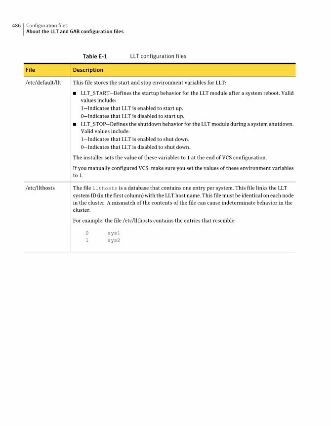
Table E-1 LLT configuration files
DescriptionFile
This file stores the start and stop environment variables for LLT:
■ LLT_START—Defines the startup behavior for the LLT module after a system reboot. Validvalues include:
1—Indicates that LLT is enabled to start up.
0—Indicates that LLT is disabled to start up.
■ LLT_STOP—Defines the shutdown behavior for the LLT module during a system shutdown.Valid values include:
1—Indicates that LLT is enabled to shut down.
0—Indicates that LLT is disabled to shut down.
The installer sets the value of these variables to 1 at the end of VCS configuration.
If you manually configured VCS, make sure you set the values of these environment variablesto 1.
/etc/default/llt
The file llthosts is a database that contains one entry per system. This file links the LLTsystem ID (in the first column) with the LLT host name. This file must be identical on each nodein the cluster. A mismatch of the contents of the file can cause indeterminate behavior in thecluster.
For example, the file /etc/llthosts contains the entries that resemble:
0 sys11 sys2
/etc/llthosts
Configuration filesAbout the LLT and GAB configuration files
486
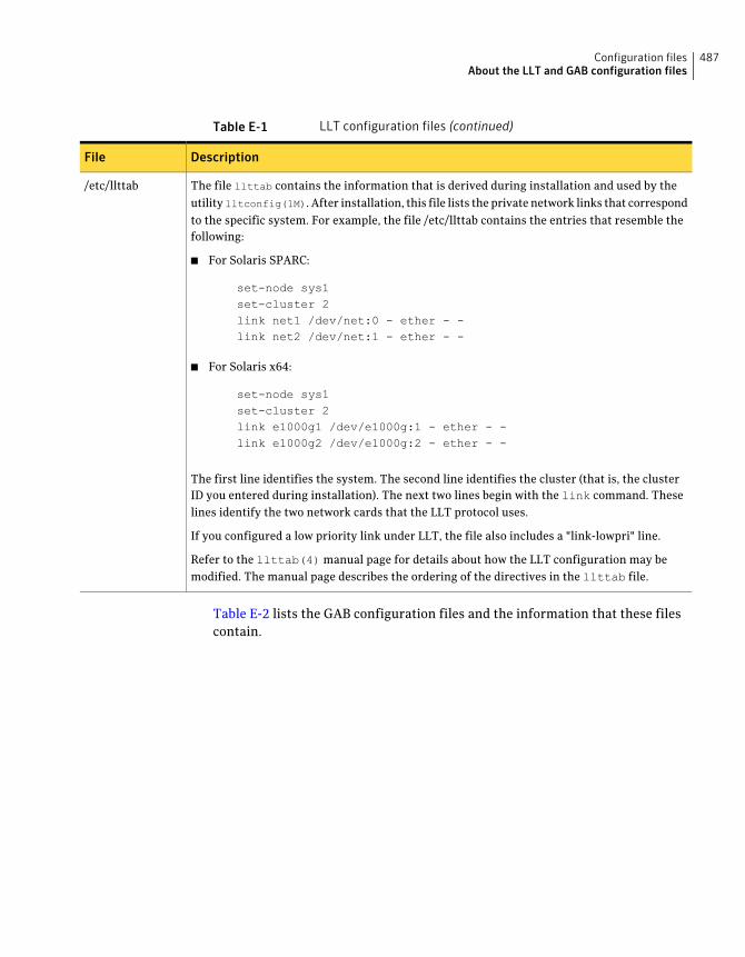
Table E-1 LLT configuration files (continued)
DescriptionFile
The file llttab contains the information that is derived during installation and used by theutility lltconfig(1M). After installation, this file lists the private network links that correspondto the specific system. For example, the file /etc/llttab contains the entries that resemble thefollowing:
■ For Solaris SPARC:
set-node sys1set-cluster 2link net1 /dev/net:0 - ether - -link net2 /dev/net:1 - ether - -
■ For Solaris x64:
set-node sys1set-cluster 2link e1000g1 /dev/e1000g:1 - ether - -link e1000g2 /dev/e1000g:2 - ether - -
The first line identifies the system. The second line identifies the cluster (that is, the clusterID you entered during installation). The next two lines begin with the link command. Theselines identify the two network cards that the LLT protocol uses.
If you configured a low priority link under LLT, the file also includes a "link-lowpri" line.
Refer to the llttab(4) manual page for details about how the LLT configuration may bemodified. The manual page describes the ordering of the directives in the llttab file.
/etc/llttab
Table E-2 lists the GAB configuration files and the information that these filescontain.
487Configuration filesAbout the LLT and GAB configuration files
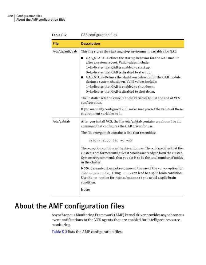
Table E-2 GAB configuration files
DescriptionFile
This file stores the start and stop environment variables for GAB:
■ GAB_START—Defines the startup behavior for the GAB moduleafter a system reboot. Valid values include:
1—Indicates that GAB is enabled to start up.
0—Indicates that GAB is disabled to start up.
■ GAB_STOP—Defines the shutdown behavior for the GAB moduleduring a system shutdown. Valid values include:
1—Indicates that GAB is enabled to shut down.
0—Indicates that GAB is disabled to shut down.
The installer sets the value of these variables to 1 at the end of VCSconfiguration.
If you manually configured VCS, make sure you set the values of theseenvironment variables to 1.
/etc/default/gab
After you install VCS, the file /etc/gabtab contains a gabconfig(1)command that configures the GAB driver for use.
The file /etc/gabtab contains a line that resembles:
/sbin/gabconfig -c -nN
The -c option configures the driver for use. The -nN specifies that thecluster is not formed until at leastNnodes are ready to form the cluster.Symantec recommends that you set N to be the total number of nodesin the cluster.
Note: Symantec does not recommend the use of the -c -x option for/sbin/gabconfig. Using -c -x can lead to a split-brain condition.Use the -c option for /sbin/gabconfig to avoid a split-braincondition.
Note:
/etc/gabtab
About the AMF configuration filesAsynchronous Monitoring Framework (AMF) kernel driver provides asynchronousevent notifications to the VCS agents that are enabled for intelligent resourcemonitoring.
Table E-3 lists the AMF configuration files.
Configuration filesAbout the AMF configuration files
488
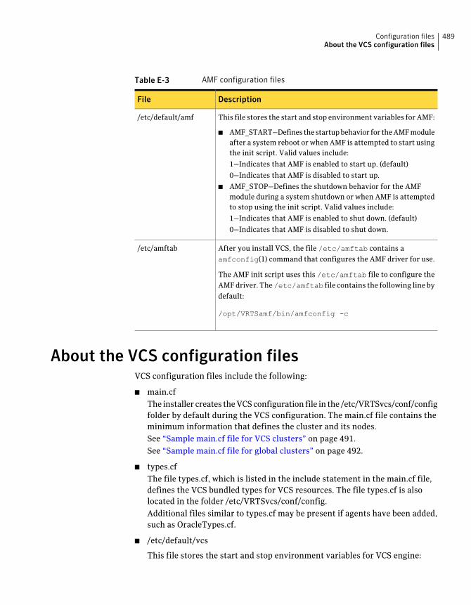
Table E-3 AMF configuration files
DescriptionFile
This file stores the start and stop environment variables for AMF:
■ AMF_START—Defines the startup behavior for the AMF moduleafter a system reboot or when AMF is attempted to start usingthe init script. Valid values include:
1—Indicates that AMF is enabled to start up. (default)
0—Indicates that AMF is disabled to start up.
■ AMF_STOP—Defines the shutdown behavior for the AMFmodule during a system shutdown or when AMF is attemptedto stop using the init script. Valid values include:
1—Indicates that AMF is enabled to shut down. (default)
0—Indicates that AMF is disabled to shut down.
/etc/default/amf
After you install VCS, the file /etc/amftab contains aamfconfig(1) command that configures the AMF driver for use.
The AMF init script uses this /etc/amftab file to configure theAMF driver. The/etc/amftab file contains the following line bydefault:
/opt/VRTSamf/bin/amfconfig -c
/etc/amftab
About the VCS configuration filesVCS configuration files include the following:
■ main.cfThe installer creates the VCS configuration file in the /etc/VRTSvcs/conf/configfolder by default during the VCS configuration. The main.cf file contains theminimum information that defines the cluster and its nodes.See “Sample main.cf file for VCS clusters” on page 491.See “Sample main.cf file for global clusters” on page 492.
■ types.cfThe file types.cf, which is listed in the include statement in the main.cf file,defines the VCS bundled types for VCS resources. The file types.cf is alsolocated in the folder /etc/VRTSvcs/conf/config.Additional files similar to types.cf may be present if agents have been added,such as OracleTypes.cf.
■ /etc/default/vcs
This file stores the start and stop environment variables for VCS engine:
489Configuration filesAbout the VCS configuration files
■ VCS_START—Defines the startup behavior for VCS engine after a systemreboot. Valid values include:1—Indicates that VCS engine is enabled to start up.0—Indicates that VCS engine is disabled to start up.
■ VCS_STOP—Defines the shutdown behavior for VCS engine during a systemshutdown. Valid values include:1—Indicates that VCS engine is enabled to shut down.0—Indicates that VCS engine is disabled to shut down.The installer sets the value of these variables to 1 at the end of VCSconfiguration.If you manually configured VCS, make sure you set the values of theseenvironment variables to 1.
■ ONENODE-Option for VCS to form a single node cluster. Valid valuesinclude:Yes-Indicates that VCS is started as a single-node cluster.No-Indicates that VCS is not set to form a single-node cluster.
Note the following information about the VCS configuration file after installingand configuring VCS:
■ The cluster definition includes the cluster information that you providedduring the configuration. This definition includes the cluster name, clusteraddress, and the names of users and administrators of the cluster.Notice that the cluster has an attribute UserNames. The installvcs programcreates a user "admin" whose password is encrypted; the word "password" isthe default password.
■ If you set up the optional I/O fencing feature for VCS, then the UseFence =SCSI3 attribute is present.
■ If you configured the cluster in secure mode, the main.cf includes "SecureClus= 1" cluster attribute.
■ The installvcs program creates the ClusterService service group if youconfigured the virtual IP, SMTP, SNMP, or global cluster options.
The service group also has the following characteristics:
■ The group includes the IP and NIC resources.
■ The service group also includes the notifier resource configuration, whichis based on your input to installvcs program prompts about notification.
■ The installvcs program also creates a resource dependency tree.
■ If you set up global clusters, the ClusterService service group contains anApplication resource, wac (wide-area connector). This resource’s attributes
Configuration filesAbout the VCS configuration files
490
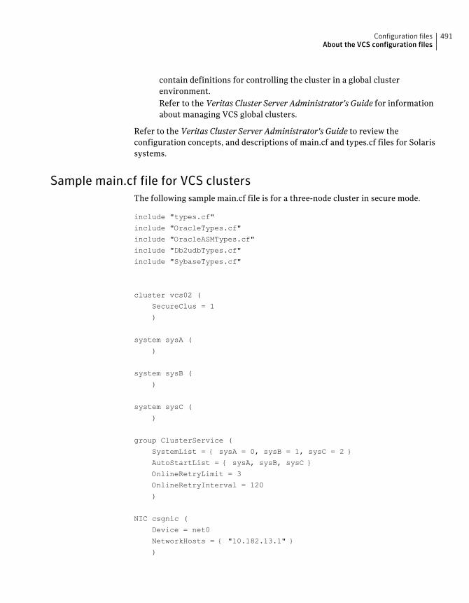
contain definitions for controlling the cluster in a global clusterenvironment.Refer to the Veritas Cluster Server Administrator's Guide for informationabout managing VCS global clusters.
Refer to the Veritas Cluster Server Administrator's Guide to review theconfiguration concepts, and descriptions of main.cf and types.cf files for Solarissystems.
Sample main.cf file for VCS clustersThe following sample main.cf file is for a three-node cluster in secure mode.
include "types.cf"
include "OracleTypes.cf"
include "OracleASMTypes.cf"
include "Db2udbTypes.cf"
include "SybaseTypes.cf"
cluster vcs02 (
SecureClus = 1
)
system sysA (
)
system sysB (
)
system sysC (
)
group ClusterService (
SystemList = { sysA = 0, sysB = 1, sysC = 2 }
AutoStartList = { sysA, sysB, sysC }
OnlineRetryLimit = 3
OnlineRetryInterval = 120
)
NIC csgnic (
Device = net0
NetworkHosts = { "10.182.13.1" }
)
491Configuration filesAbout the VCS configuration files
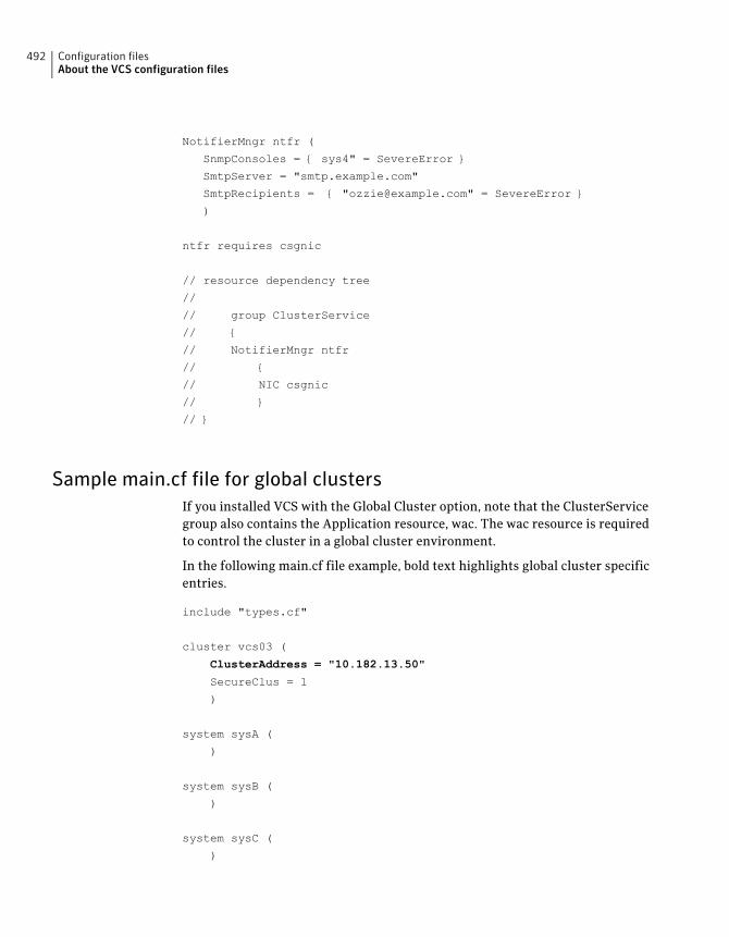
NotifierMngr ntfr (
SnmpConsoles = { sys4" = SevereError }
SmtpServer = "smtp.example.com"
SmtpRecipients = { "[email protected]" = SevereError }
)
ntfr requires csgnic
// resource dependency tree
//
// group ClusterService
// {
// NotifierMngr ntfr
// {
// NIC csgnic
// }
// }
Sample main.cf file for global clustersIf you installed VCS with the Global Cluster option, note that the ClusterServicegroup also contains the Application resource, wac. The wac resource is requiredto control the cluster in a global cluster environment.
In the following main.cf file example, bold text highlights global cluster specificentries.
include "types.cf"
cluster vcs03 (
ClusterAddress = "10.182.13.50"
SecureClus = 1
)
system sysA (
)
system sysB (
)
system sysC (
)
Configuration filesAbout the VCS configuration files
492
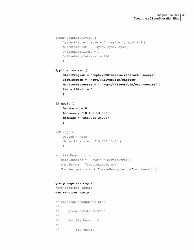
group ClusterService (
SystemList = { sysA = 0, sysB = 1, sysC = 2 }
AutoStartList = { sysA, sysB, sysC }
OnlineRetryLimit = 3
OnlineRetryInterval = 120
)
Application wac (
StartProgram = "/opt/VRTSvcs/bin/wacstart -secure"
StopProgram = "/opt/VRTSvcs/bin/wacstop"
MonitorProcesses = { "/opt/VRTSvcs/bin/wac -secure" }
RestartLimit = 3
)
IP gcoip (
Device = net0
Address = "10.182.13.50"
NetMask = "255.255.240.0"
)
NIC csgnic (
Device = net0
NetworkHosts = { "10.182.13.1" }
)
NotifierMngr ntfr (
SnmpConsoles = { sys4" = SevereError }
SmtpServer = "smtp.example.com"
SmtpRecipients = { "[email protected]" = SevereError }
)
gcoip requires csgnic
ntfr requires csgnic
wac requires gcoip
// resource dependency tree
//
// group ClusterService
// {
// NotifierMngr ntfr
// {
// NIC csgnic
493Configuration filesAbout the VCS configuration files
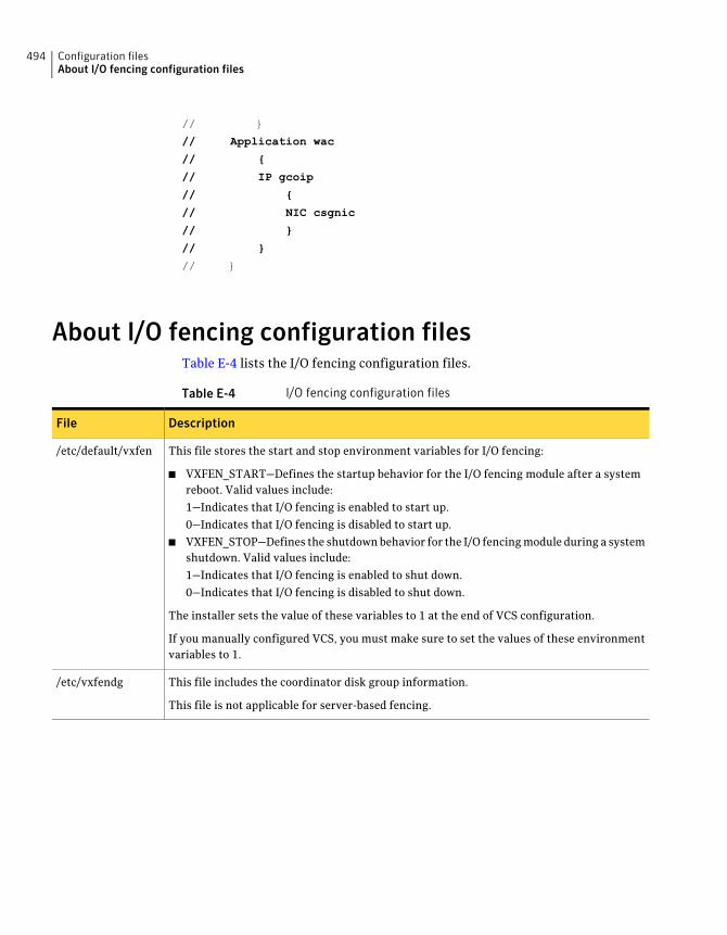
// }
// Application wac
// {
// IP gcoip
// {
// NIC csgnic
// }
// }
// }
About I/O fencing configuration filesTable E-4 lists the I/O fencing configuration files.
Table E-4 I/O fencing configuration files
DescriptionFile
This file stores the start and stop environment variables for I/O fencing:
■ VXFEN_START—Defines the startup behavior for the I/O fencing module after a systemreboot. Valid values include:
1—Indicates that I/O fencing is enabled to start up.
0—Indicates that I/O fencing is disabled to start up.
■ VXFEN_STOP—Defines the shutdown behavior for the I/O fencing module during a systemshutdown. Valid values include:
1—Indicates that I/O fencing is enabled to shut down.
0—Indicates that I/O fencing is disabled to shut down.
The installer sets the value of these variables to 1 at the end of VCS configuration.
If you manually configured VCS, you must make sure to set the values of these environmentvariables to 1.
/etc/default/vxfen
This file includes the coordinator disk group information.
This file is not applicable for server-based fencing.
/etc/vxfendg
Configuration filesAbout I/O fencing configuration files
494
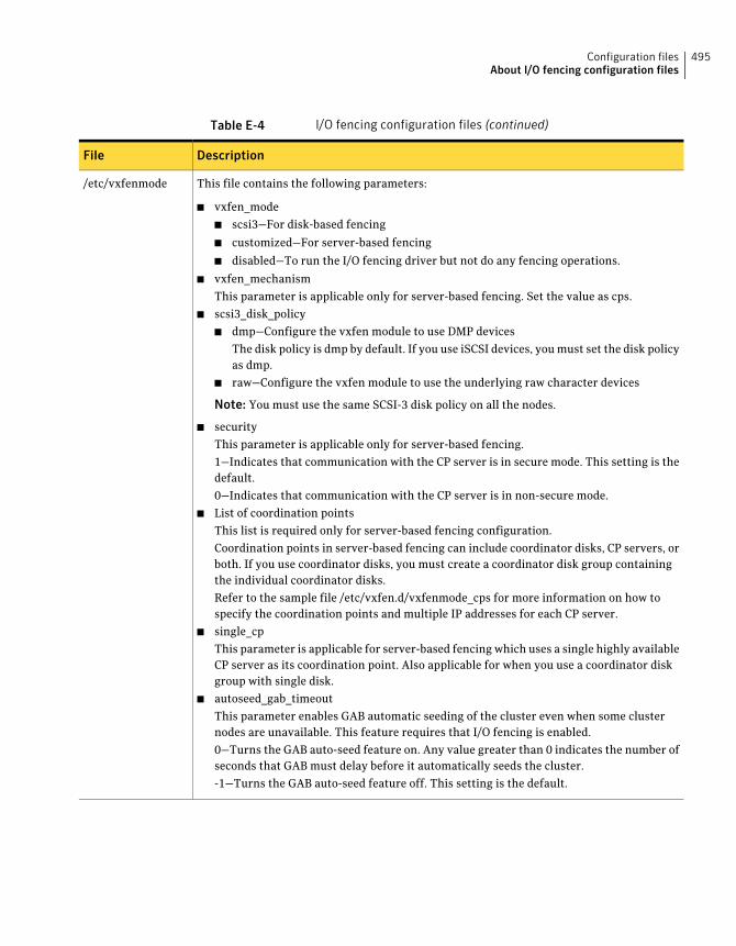
Table E-4 I/O fencing configuration files (continued)
DescriptionFile
This file contains the following parameters:
■ vxfen_mode
■ scsi3—For disk-based fencing
■ customized—For server-based fencing
■ disabled—To run the I/O fencing driver but not do any fencing operations.
■ vxfen_mechanism
This parameter is applicable only for server-based fencing. Set the value as cps.
■ scsi3_disk_policy
■ dmp—Configure the vxfen module to use DMP devices
The disk policy is dmp by default. If you use iSCSI devices, you must set the disk policyas dmp.
■ raw—Configure the vxfen module to use the underlying raw character devices
Note: You must use the same SCSI-3 disk policy on all the nodes.
■ security
This parameter is applicable only for server-based fencing.
1—Indicates that communication with the CP server is in secure mode. This setting is thedefault.
0—Indicates that communication with the CP server is in non-secure mode.
■ List of coordination points
This list is required only for server-based fencing configuration.
Coordination points in server-based fencing can include coordinator disks, CP servers, orboth. If you use coordinator disks, you must create a coordinator disk group containingthe individual coordinator disks.
Refer to the sample file /etc/vxfen.d/vxfenmode_cps for more information on how tospecify the coordination points and multiple IP addresses for each CP server.
■ single_cp
This parameter is applicable for server-based fencing which uses a single highly availableCP server as its coordination point. Also applicable for when you use a coordinator diskgroup with single disk.
■ autoseed_gab_timeout
This parameter enables GAB automatic seeding of the cluster even when some clusternodes are unavailable. This feature requires that I/O fencing is enabled.
0—Turns the GAB auto-seed feature on. Any value greater than 0 indicates the number ofseconds that GAB must delay before it automatically seeds the cluster.
-1—Turns the GAB auto-seed feature off. This setting is the default.
/etc/vxfenmode
495Configuration filesAbout I/O fencing configuration files
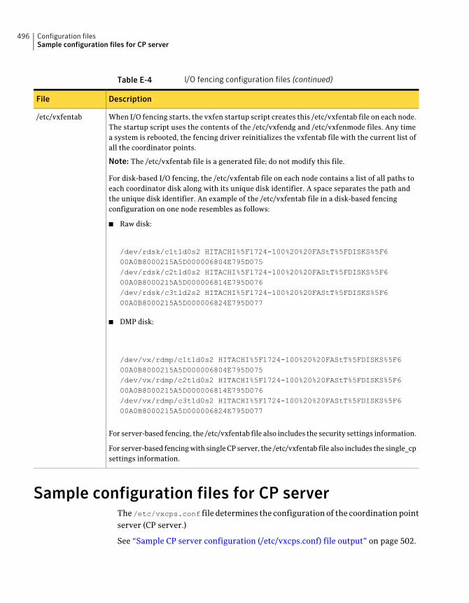
Table E-4 I/O fencing configuration files (continued)
DescriptionFile
When I/O fencing starts, the vxfen startup script creates this /etc/vxfentab file on each node.The startup script uses the contents of the /etc/vxfendg and /etc/vxfenmode files. Any timea system is rebooted, the fencing driver reinitializes the vxfentab file with the current list ofall the coordinator points.
Note: The /etc/vxfentab file is a generated file; do not modify this file.
For disk-based I/O fencing, the /etc/vxfentab file on each node contains a list of all paths toeach coordinator disk along with its unique disk identifier. A space separates the path andthe unique disk identifier. An example of the /etc/vxfentab file in a disk-based fencingconfiguration on one node resembles as follows:
■ Raw disk:
/dev/rdsk/c1t1d0s2 HITACHI%5F1724-100%20%20FAStT%5FDISKS%5F600A0B8000215A5D000006804E795D075/dev/rdsk/c2t1d0s2 HITACHI%5F1724-100%20%20FAStT%5FDISKS%5F600A0B8000215A5D000006814E795D076/dev/rdsk/c3t1d2s2 HITACHI%5F1724-100%20%20FAStT%5FDISKS%5F600A0B8000215A5D000006824E795D077
■ DMP disk:
/dev/vx/rdmp/c1t1d0s2 HITACHI%5F1724-100%20%20FAStT%5FDISKS%5F600A0B8000215A5D000006804E795D075/dev/vx/rdmp/c2t1d0s2 HITACHI%5F1724-100%20%20FAStT%5FDISKS%5F600A0B8000215A5D000006814E795D076/dev/vx/rdmp/c3t1d0s2 HITACHI%5F1724-100%20%20FAStT%5FDISKS%5F600A0B8000215A5D000006824E795D077
For server-based fencing, the /etc/vxfentab file also includes the security settings information.
For server-based fencing with single CP server, the /etc/vxfentab file also includes the single_cpsettings information.
/etc/vxfentab
Sample configuration files for CP serverThe /etc/vxcps.conf file determines the configuration of the coordination pointserver (CP server.)
See “Sample CP server configuration (/etc/vxcps.conf) file output” on page 502.
Configuration filesSample configuration files for CP server
496
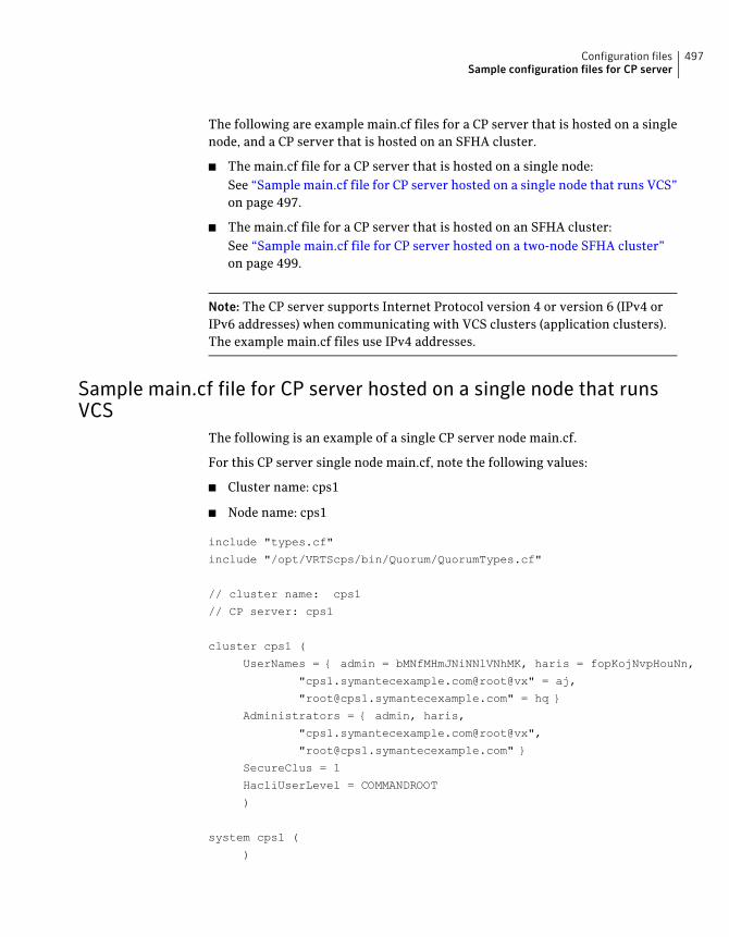
The following are example main.cf files for a CP server that is hosted on a singlenode, and a CP server that is hosted on an SFHA cluster.
■ The main.cf file for a CP server that is hosted on a single node:See “Sample main.cf file for CP server hosted on a single node that runs VCS”on page 497.
■ The main.cf file for a CP server that is hosted on an SFHA cluster:See “Sample main.cf file for CP server hosted on a two-node SFHA cluster”on page 499.
Note: The CP server supports Internet Protocol version 4 or version 6 (IPv4 orIPv6 addresses) when communicating with VCS clusters (application clusters).The example main.cf files use IPv4 addresses.
Sample main.cf file for CP server hosted on a single node that runsVCS
The following is an example of a single CP server node main.cf.
For this CP server single node main.cf, note the following values:
■ Cluster name: cps1
■ Node name: cps1
include "types.cf"
include "/opt/VRTScps/bin/Quorum/QuorumTypes.cf"
// cluster name: cps1
// CP server: cps1
cluster cps1 (
UserNames = { admin = bMNfMHmJNiNNlVNhMK, haris = fopKojNvpHouNn,
"cps1.symantecexample.com@root@vx" = aj,
"[email protected]" = hq }
Administrators = { admin, haris,
"cps1.symantecexample.com@root@vx",
SecureClus = 1
HacliUserLevel = COMMANDROOT
)
system cps1 (
)
497Configuration filesSample configuration files for CP server
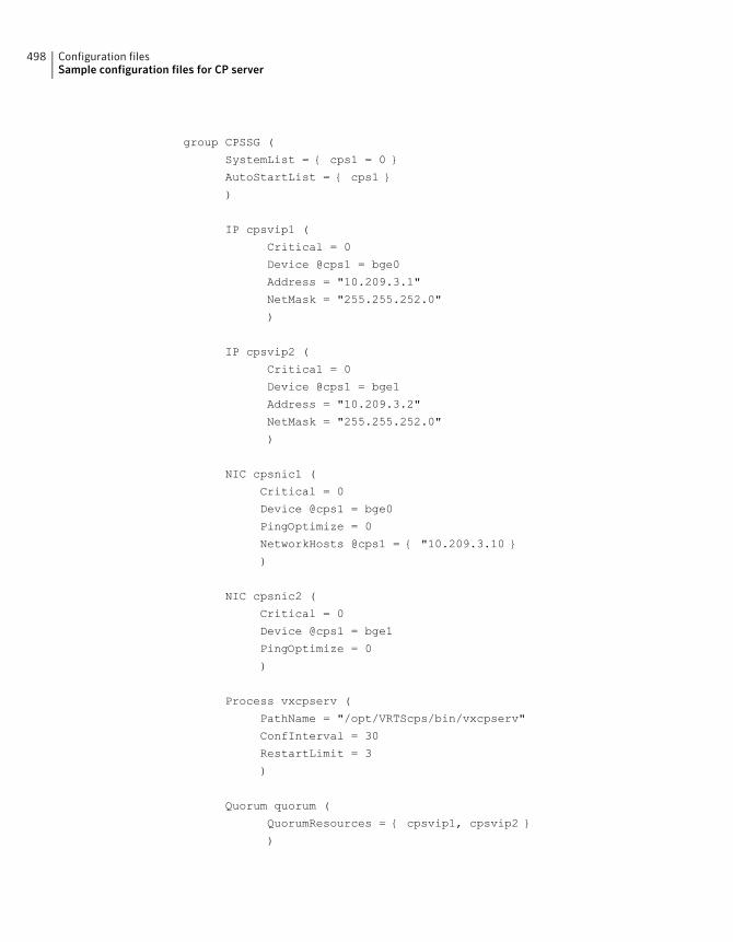
group CPSSG (
SystemList = { cps1 = 0 }
AutoStartList = { cps1 }
)
IP cpsvip1 (
Critical = 0
Device @cps1 = bge0
Address = "10.209.3.1"
NetMask = "255.255.252.0"
)
IP cpsvip2 (
Critical = 0
Device @cps1 = bge1
Address = "10.209.3.2"
NetMask = "255.255.252.0"
)
NIC cpsnic1 (
Critical = 0
Device @cps1 = bge0
PingOptimize = 0
NetworkHosts @cps1 = { "10.209.3.10 }
)
NIC cpsnic2 (
Critical = 0
Device @cps1 = bge1
PingOptimize = 0
)
Process vxcpserv (
PathName = "/opt/VRTScps/bin/vxcpserv"
ConfInterval = 30
RestartLimit = 3
)
Quorum quorum (
QuorumResources = { cpsvip1, cpsvip2 }
)
Configuration filesSample configuration files for CP server
498
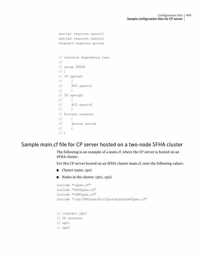
cpsvip1 requires cpsnic1
cpsvip2 requires cpsnic2
vxcpserv requires quorum
// resource dependency tree
//
// group CPSSG
// {
// IP cpsvip1
// {
// NIC cpsnic1
// }
// IP cpsvip2
// {
// NIC cpsnic2
// }
// Process vxcpserv
// {
// Quorum quorum
// }
// }
Sample main.cf file for CP server hosted on a two-node SFHA clusterThe following is an example of a main.cf, where the CP server is hosted on anSFHA cluster.
For this CP server hosted on an SFHA cluster main.cf, note the following values:
■ Cluster name: cps1
■ Nodes in the cluster: cps1, cps2
include "types.cf"
include "CFSTypes.cf"
include "CVMTypes.cf"
include "/opt/VRTScps/bin/Quorum/QuorumTypes.cf"
// cluster: cps1
// CP servers:
// cps1
// cps2
499Configuration filesSample configuration files for CP server
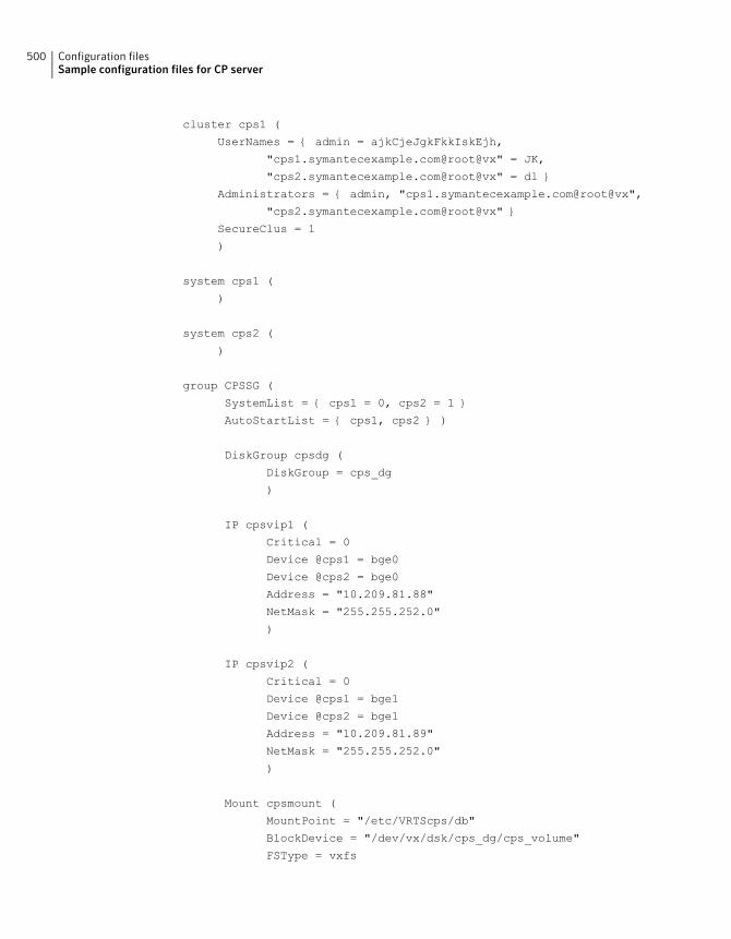
cluster cps1 (
UserNames = { admin = ajkCjeJgkFkkIskEjh,
"cps1.symantecexample.com@root@vx" = JK,
"cps2.symantecexample.com@root@vx" = dl }
Administrators = { admin, "cps1.symantecexample.com@root@vx",
"cps2.symantecexample.com@root@vx" }
SecureClus = 1
)
system cps1 (
)
system cps2 (
)
group CPSSG (
SystemList = { cps1 = 0, cps2 = 1 }
AutoStartList = { cps1, cps2 } )
DiskGroup cpsdg (
DiskGroup = cps_dg
)
IP cpsvip1 (
Critical = 0
Device @cps1 = bge0
Device @cps2 = bge0
Address = "10.209.81.88"
NetMask = "255.255.252.0"
)
IP cpsvip2 (
Critical = 0
Device @cps1 = bge1
Device @cps2 = bge1
Address = "10.209.81.89"
NetMask = "255.255.252.0"
)
Mount cpsmount (
MountPoint = "/etc/VRTScps/db"
BlockDevice = "/dev/vx/dsk/cps_dg/cps_volume"
FSType = vxfs
Configuration filesSample configuration files for CP server
500
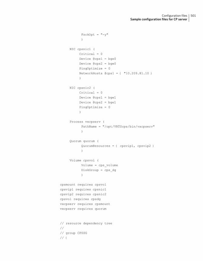
FsckOpt = "-y"
)
NIC cpsnic1 (
Critical = 0
Device @cps1 = bge0
Device @cps2 = bge0
PingOptimize = 0
NetworkHosts @cps1 = { "10.209.81.10 }
)
NIC cpsnic2 (
Critical = 0
Device @cps1 = bge1
Device @cps2 = bge1
PingOptimize = 0
)
Process vxcpserv (
PathName = "/opt/VRTScps/bin/vxcpserv"
)
Quorum quorum (
QuorumResources = { cpsvip1, cpsvip2 }
)
Volume cpsvol (
Volume = cps_volume
DiskGroup = cps_dg
)
cpsmount requires cpsvol
cpsvip1 requires cpsnic1
cpsvip2 requires cpsnic2
cpsvol requires cpsdg
vxcpserv requires cpsmount
vxcpserv requires quorum
// resource dependency tree
//
// group CPSSG
// {
501Configuration filesSample configuration files for CP server
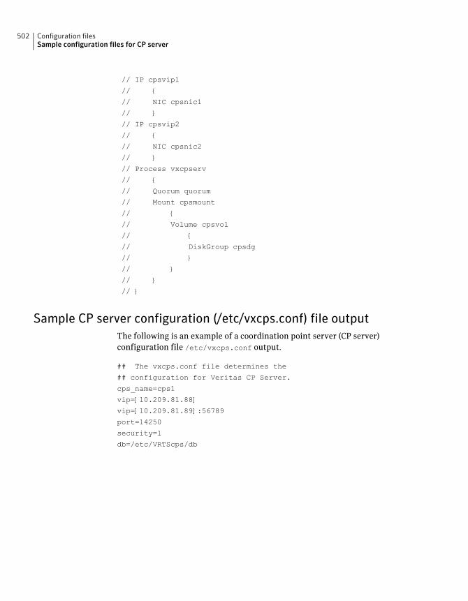
// IP cpsvip1
// {
// NIC cpsnic1
// }
// IP cpsvip2
// {
// NIC cpsnic2
// }
// Process vxcpserv
// {
// Quorum quorum
// Mount cpsmount
// {
// Volume cpsvol
// {
// DiskGroup cpsdg
// }
// }
// }
// }
Sample CP server configuration (/etc/vxcps.conf) file outputThe following is an example of a coordination point server (CP server)configuration file /etc/vxcps.conf output.
## The vxcps.conf file determines the
## configuration for Veritas CP Server.
cps_name=cps1
vip=[10.209.81.88]
vip=[10.209.81.89]:56789
port=14250
security=1
db=/etc/VRTScps/db
Configuration filesSample configuration files for CP server
502
Installing VCS on a singlenode
This appendix includes the following topics:
■ About installing VCS on a single node
■ Creating a single-node cluster using the installer program
■ Creating a single-node cluster manually
■ Setting the path variable for a manual single node installation
■ Installing VCS software manually on a single node
■ Configuring VCS
■ Verifying single-node operation
About installing VCS on a single nodeYou can install VCS 6.0.1 on a single node. You can subsequently add anothernode to the single-node cluster to form a multinode cluster. You can also preparea single node cluster for addition into a multi-node cluster. Single node clusterscan be used for testing as well.
You can install VCS onto a single node using the installer program or you can addit manually.
See “Creating a single-node cluster using the installer program” on page 504.
See “Creating a single-node cluster manually” on page 505.
FAppendix
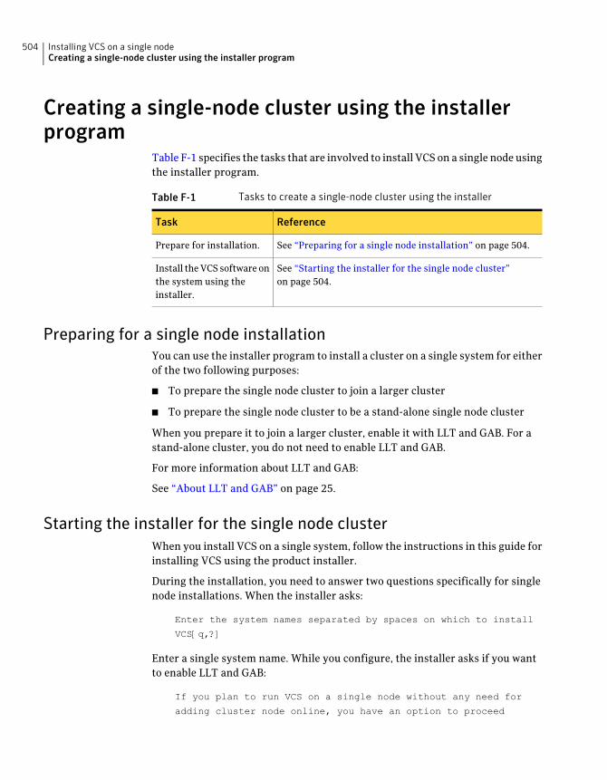
Creating a single-node cluster using the installerprogram
Table F-1 specifies the tasks that are involved to install VCS on a single node usingthe installer program.
Table F-1 Tasks to create a single-node cluster using the installer
ReferenceTask
See “Preparing for a single node installation” on page 504.Prepare for installation.
See “Starting the installer for the single node cluster”on page 504.
Install the VCS software onthe system using theinstaller.
Preparing for a single node installationYou can use the installer program to install a cluster on a single system for eitherof the two following purposes:
■ To prepare the single node cluster to join a larger cluster
■ To prepare the single node cluster to be a stand-alone single node cluster
When you prepare it to join a larger cluster, enable it with LLT and GAB. For astand-alone cluster, you do not need to enable LLT and GAB.
For more information about LLT and GAB:
See “About LLT and GAB” on page 25.
Starting the installer for the single node clusterWhen you install VCS on a single system, follow the instructions in this guide forinstalling VCS using the product installer.
During the installation, you need to answer two questions specifically for singlenode installations. When the installer asks:
Enter the system names separated by spaces on which to install
VCS[q,?]
Enter a single system name. While you configure, the installer asks if you wantto enable LLT and GAB:
If you plan to run VCS on a single node without any need for
adding cluster node online, you have an option to proceed
Installing VCS on a single nodeCreating a single-node cluster using the installer program
504
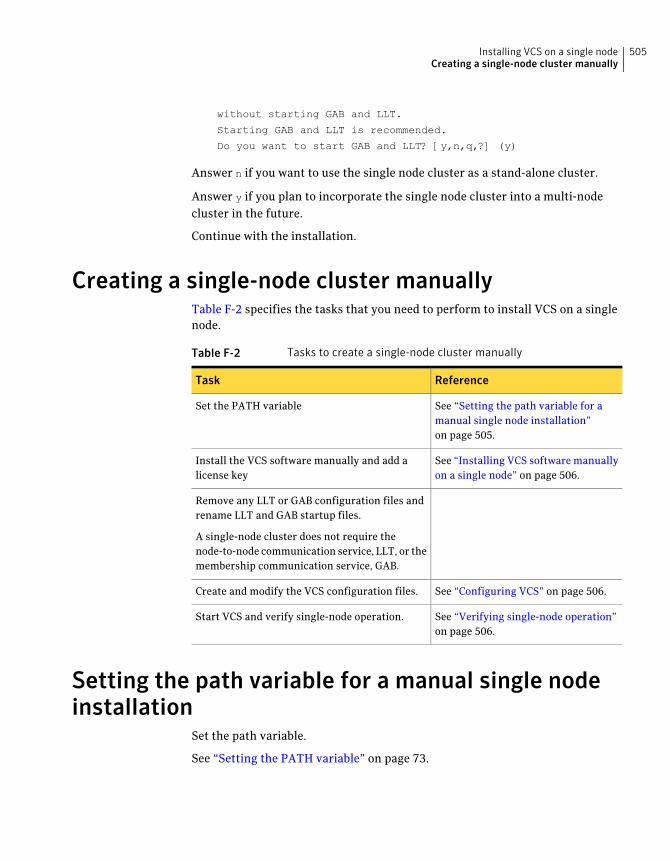
without starting GAB and LLT.
Starting GAB and LLT is recommended.
Do you want to start GAB and LLT? [y,n,q,?] (y)
Answer n if you want to use the single node cluster as a stand-alone cluster.
Answer y if you plan to incorporate the single node cluster into a multi-nodecluster in the future.
Continue with the installation.
Creating a single-node cluster manuallyTable F-2 specifies the tasks that you need to perform to install VCS on a singlenode.
Table F-2 Tasks to create a single-node cluster manually
ReferenceTask
See “Setting the path variable for amanual single node installation”on page 505.
Set the PATH variable
See “Installing VCS software manuallyon a single node” on page 506.
Install the VCS software manually and add alicense key
Remove any LLT or GAB configuration files andrename LLT and GAB startup files.
A single-node cluster does not require thenode-to-node communication service, LLT, or themembership communication service, GAB.
See “Configuring VCS” on page 506.Create and modify the VCS configuration files.
See “Verifying single-node operation”on page 506.
Start VCS and verify single-node operation.
Setting the path variable for a manual single nodeinstallation
Set the path variable.
See “Setting the PATH variable” on page 73.
505Installing VCS on a single nodeCreating a single-node cluster manually
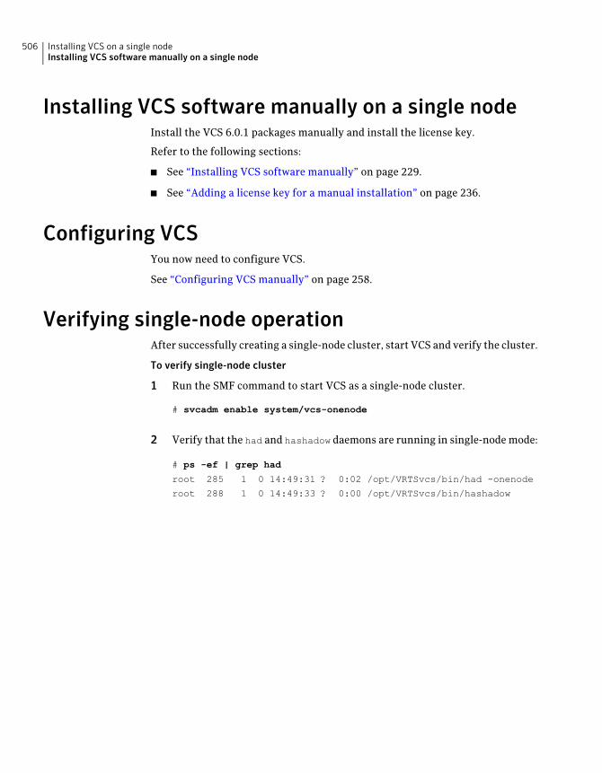
Installing VCS software manually on a single nodeInstall the VCS 6.0.1 packages manually and install the license key.
Refer to the following sections:
■ See “Installing VCS software manually” on page 229.
■ See “Adding a license key for a manual installation” on page 236.
Configuring VCSYou now need to configure VCS.
See “Configuring VCS manually” on page 258.
Verifying single-node operationAfter successfully creating a single-node cluster, start VCS and verify the cluster.
To verify single-node cluster
1 Run the SMF command to start VCS as a single-node cluster.
# svcadm enable system/vcs-onenode
2 Verify that the had and hashadow daemons are running in single-node mode:
# ps -ef | grep had
root 285 1 0 14:49:31 ? 0:02 /opt/VRTSvcs/bin/had -onenode
root 288 1 0 14:49:33 ? 0:00 /opt/VRTSvcs/bin/hashadow
Installing VCS on a single nodeInstalling VCS software manually on a single node
506
Configuring LLT over UDP
This appendix includes the following topics:
■ Using the UDP layer for LLT
■ Manually configuring LLT over UDP using IPv4
■ Manually configuring LLT over UDP using IPv6
■ LLT over UDP sample /etc/llttab
Using the UDP layer for LLTVCS provides the option of using LLT over the UDP (User Datagram Protocol)layer for clusters using wide-area networks and routers. UDP makes LLT packetsroutable and thus able to span longer distances more economically.
When to use LLT over UDPUse LLT over UDP in the following situations:
■ LLT must be used over WANs
■ When hardware, such as blade servers, do not support LLT over Ethernet
LLT over UDP is slower than LLT over Ethernet. Use LLT over UDP only when thehardware configuration makes it necessary.
Manually configuring LLT over UDP using IPv4The following checklist is to configure LLT over UDP:
■ Make sure that the LLT private links are on separate subnets. Set the broadcastaddress in /etc/llttab explicitly depending on the subnet for each link.
GAppendix
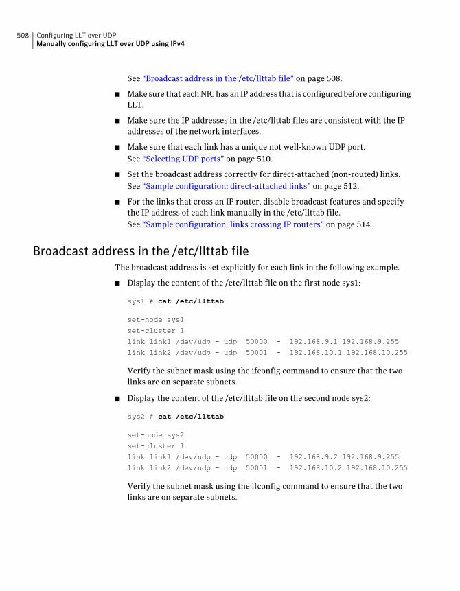
See “Broadcast address in the /etc/llttab file” on page 508.
■ Make sure that each NIC has an IP address that is configured before configuringLLT.
■ Make sure the IP addresses in the /etc/llttab files are consistent with the IPaddresses of the network interfaces.
■ Make sure that each link has a unique not well-known UDP port.See “Selecting UDP ports” on page 510.
■ Set the broadcast address correctly for direct-attached (non-routed) links.See “Sample configuration: direct-attached links” on page 512.
■ For the links that cross an IP router, disable broadcast features and specifythe IP address of each link manually in the /etc/llttab file.See “Sample configuration: links crossing IP routers” on page 514.
Broadcast address in the /etc/llttab fileThe broadcast address is set explicitly for each link in the following example.
■ Display the content of the /etc/llttab file on the first node sys1:
sys1 # cat /etc/llttab
set-node sys1
set-cluster 1
link link1 /dev/udp - udp 50000 - 192.168.9.1 192.168.9.255
link link2 /dev/udp - udp 50001 - 192.168.10.1 192.168.10.255
Verify the subnet mask using the ifconfig command to ensure that the twolinks are on separate subnets.
■ Display the content of the /etc/llttab file on the second node sys2:
sys2 # cat /etc/llttab
set-node sys2
set-cluster 1
link link1 /dev/udp - udp 50000 - 192.168.9.2 192.168.9.255
link link2 /dev/udp - udp 50001 - 192.168.10.2 192.168.10.255
Verify the subnet mask using the ifconfig command to ensure that the twolinks are on separate subnets.
Configuring LLT over UDPManually configuring LLT over UDP using IPv4
508
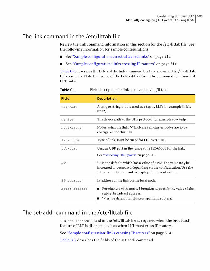
The link command in the /etc/llttab fileReview the link command information in this section for the /etc/llttab file. Seethe following information for sample configurations:
■ See “Sample configuration: direct-attached links” on page 512.
■ See “Sample configuration: links crossing IP routers” on page 514.
Table G-1 describes the fields of the link command that are shown in the /etc/llttabfile examples. Note that some of the fields differ from the command for standardLLT links.
Table G-1 Field description for link command in /etc/llttab
DescriptionField
A unique string that is used as a tag by LLT; for example link1,link2,....
tag-name
The device path of the UDP protocol; for example /dev/udp.device
Nodes using the link. "-" indicates all cluster nodes are to beconfigured for this link.
node-range
Type of link; must be "udp" for LLT over UDP.link-type
Unique UDP port in the range of 49152-65535 for the link.
See “Selecting UDP ports” on page 510.
udp-port
"-" is the default, which has a value of 8192. The value may beincreased or decreased depending on the configuration. Use thelltstat -l command to display the current value.
MTU
IP address of the link on the local node.IP address
■ For clusters with enabled broadcasts, specify the value of thesubnet broadcast address.
■ "-" is the default for clusters spanning routers.
bcast-address
The set-addr command in the /etc/llttab fileThe set-addr command in the /etc/llttab file is required when the broadcastfeature of LLT is disabled, such as when LLT must cross IP routers.
See “Sample configuration: links crossing IP routers” on page 514.
Table G-2 describes the fields of the set-addr command.
509Configuring LLT over UDPManually configuring LLT over UDP using IPv4
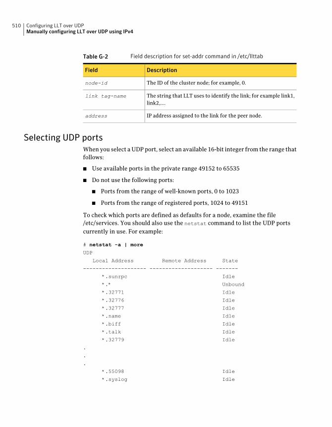
Table G-2 Field description for set-addr command in /etc/llttab
DescriptionField
The ID of the cluster node; for example, 0.node-id
The string that LLT uses to identify the link; for example link1,link2,....
link tag-name
IP address assigned to the link for the peer node.address
Selecting UDP portsWhen you select a UDP port, select an available 16-bit integer from the range thatfollows:
■ Use available ports in the private range 49152 to 65535
■ Do not use the following ports:
■ Ports from the range of well-known ports, 0 to 1023
■ Ports from the range of registered ports, 1024 to 49151
To check which ports are defined as defaults for a node, examine the file/etc/services. You should also use the netstat command to list the UDP portscurrently in use. For example:
# netstat -a | more
UDP
Local Address Remote Address State
-------------------- -------------------- -------
*.sunrpc Idle
*.* Unbound
*.32771 Idle
*.32776 Idle
*.32777 Idle
*.name Idle
*.biff Idle
*.talk Idle
*.32779 Idle
.
.
.
*.55098 Idle
*.syslog Idle
Configuring LLT over UDPManually configuring LLT over UDP using IPv4
510
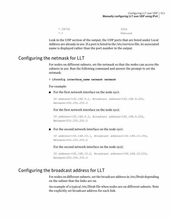
*.58702 Idle
*.* Unbound
Look in the UDP section of the output; the UDP ports that are listed under LocalAddress are already in use. If a port is listed in the /etc/services file, its associatedname is displayed rather than the port number in the output.
Configuring the netmask for LLTFor nodes on different subnets, set the netmask so that the nodes can access thesubnets in use. Run the following command and answer the prompt to set thenetmask:
# ifconfig interface_name netmask netmask
For example:
■ For the first network interface on the node sys1:
IP address=192.168.9.1, Broadcast address=192.168.9.255,
Netmask=255.255.255.0
For the first network interface on the node sys2:
IP address=192.168.9.2, Broadcast address=192.168.9.255,
Netmask=255.255.255.0
■ For the second network interface on the node sys1:
IP address=192.168.10.1, Broadcast address=192.168.10.255,
Netmask=255.255.255.0
For the second network interface on the node sys2:
IP address=192.168.10.2, Broadcast address=192.168.10.255,
Netmask=255.255.255.0
Configuring the broadcast address for LLTFor nodes on different subnets, set the broadcast address in /etc/llttab dependingon the subnet that the links are on.
An example of a typical /etc/llttab file when nodes are on different subnets. Notethe explicitly set broadcast address for each link.
511Configuring LLT over UDPManually configuring LLT over UDP using IPv4
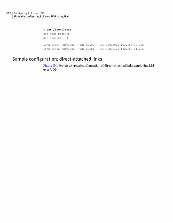
# cat /etc/llttab
set-node nodexyz
set-cluster 100
link link1 /dev/udp - udp 50000 - 192.168.30.1 192.168.30.255
link link2 /dev/udp - udp 50001 - 192.168.31.1 192.168.31.255
Sample configuration: direct-attached linksFigure G-1 depicts a typical configuration of direct-attached links employing LLTover UDP.
Configuring LLT over UDPManually configuring LLT over UDP using IPv4
512
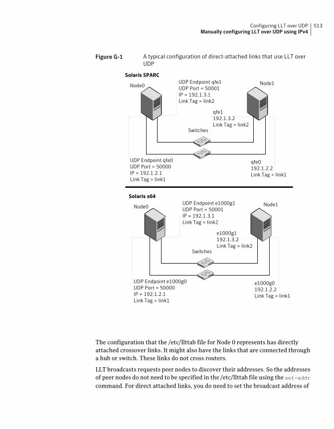
Figure G-1 A typical configuration of direct-attached links that use LLT overUDP
UDP Endpoint qfe1UDP Port = 50001IP = 192.1.3.1Link Tag = link2
UDP Endpoint qfe0UDP Port = 50000IP = 192.1.2.1Link Tag = link1
qfe1192.1.3.2Link Tag = link2
qfe0192.1.2.2Link Tag = link1
Switches
Node0 Node1
Solaris SPARC
Solaris x64UDP Endpoint e1000g1UDP Port = 50001IP = 192.1.3.1Link Tag = link2
UDP Endpoint e1000g0UDP Port = 50000IP = 192.1.2.1Link Tag = link1
e1000g1192.1.3.2Link Tag = link2
e1000g0192.1.2.2Link Tag = link1
Switches
Node0 Node1
The configuration that the /etc/llttab file for Node 0 represents has directlyattached crossover links. It might also have the links that are connected througha hub or switch. These links do not cross routers.
LLT broadcasts requests peer nodes to discover their addresses. So the addressesof peer nodes do not need to be specified in the /etc/llttab file using the set-addrcommand. For direct attached links, you do need to set the broadcast address of
513Configuring LLT over UDPManually configuring LLT over UDP using IPv4
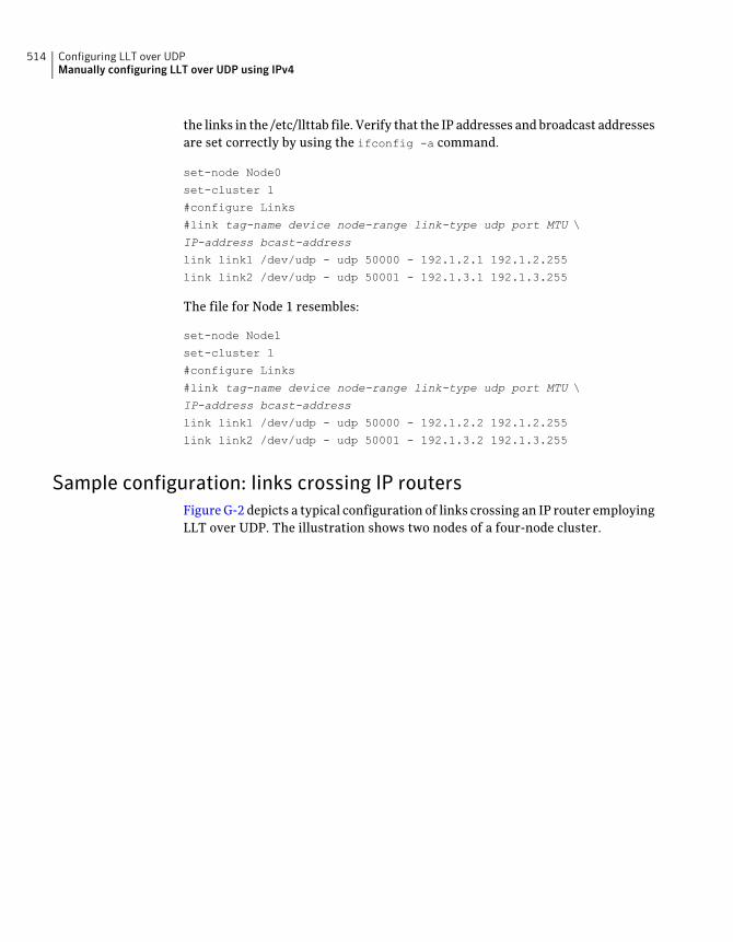
the links in the /etc/llttab file. Verify that the IP addresses and broadcast addressesare set correctly by using the ifconfig -a command.
set-node Node0
set-cluster 1
#configure Links
#link tag-name device node-range link-type udp port MTU \
IP-address bcast-address
link link1 /dev/udp - udp 50000 - 192.1.2.1 192.1.2.255
link link2 /dev/udp - udp 50001 - 192.1.3.1 192.1.3.255
The file for Node 1 resembles:
set-node Node1
set-cluster 1
#configure Links
#link tag-name device node-range link-type udp port MTU \
IP-address bcast-address
link link1 /dev/udp - udp 50000 - 192.1.2.2 192.1.2.255
link link2 /dev/udp - udp 50001 - 192.1.3.2 192.1.3.255
Sample configuration: links crossing IP routersFigure G-2 depicts a typical configuration of links crossing an IP router employingLLT over UDP. The illustration shows two nodes of a four-node cluster.
Configuring LLT over UDPManually configuring LLT over UDP using IPv4
514
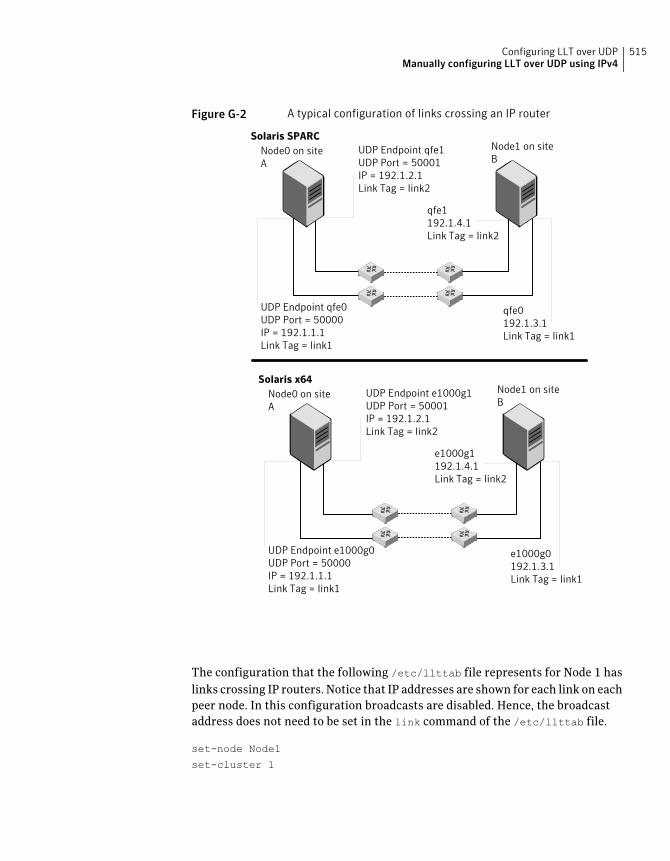
Figure G-2 A typical configuration of links crossing an IP router
UDP Endpoint qfe1UDP Port = 50001IP = 192.1.2.1Link Tag = link2
UDP Endpoint qfe0UDP Port = 50000IP = 192.1.1.1Link Tag = link1
qfe1192.1.4.1Link Tag = link2
qfe0192.1.3.1Link Tag = link1
Node0 on siteA
Node1 on siteB
Solaris SPARC
Solaris x64UDP Endpoint e1000g1UDP Port = 50001IP = 192.1.2.1Link Tag = link2
UDP Endpoint e1000g0UDP Port = 50000IP = 192.1.1.1Link Tag = link1
e1000g1192.1.4.1Link Tag = link2
e1000g0192.1.3.1Link Tag = link1
Node0 on siteA
Node1 on siteB
The configuration that the following /etc/llttab file represents for Node 1 haslinks crossing IP routers. Notice that IP addresses are shown for each link on eachpeer node. In this configuration broadcasts are disabled. Hence, the broadcastaddress does not need to be set in the link command of the /etc/llttab file.
set-node Node1
set-cluster 1
515Configuring LLT over UDPManually configuring LLT over UDP using IPv4
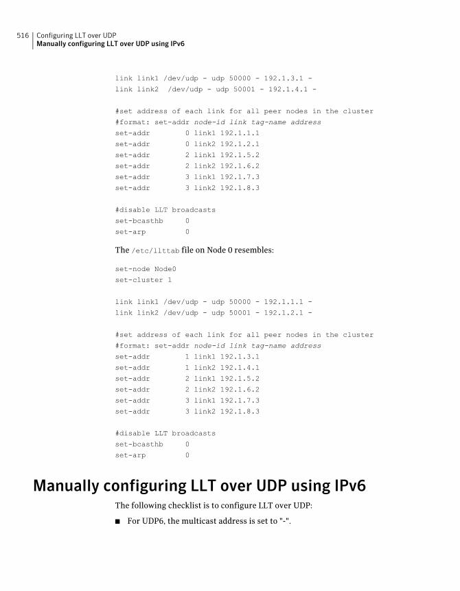
link link1 /dev/udp - udp 50000 - 192.1.3.1 -
link link2 /dev/udp - udp 50001 - 192.1.4.1 -
#set address of each link for all peer nodes in the cluster
#format: set-addr node-id link tag-name address
set-addr 0 link1 192.1.1.1
set-addr 0 link2 192.1.2.1
set-addr 2 link1 192.1.5.2
set-addr 2 link2 192.1.6.2
set-addr 3 link1 192.1.7.3
set-addr 3 link2 192.1.8.3
#disable LLT broadcasts
set-bcasthb 0
set-arp 0
The /etc/llttab file on Node 0 resembles:
set-node Node0
set-cluster 1
link link1 /dev/udp - udp 50000 - 192.1.1.1 -
link link2 /dev/udp - udp 50001 - 192.1.2.1 -
#set address of each link for all peer nodes in the cluster
#format: set-addr node-id link tag-name address
set-addr 1 link1 192.1.3.1
set-addr 1 link2 192.1.4.1
set-addr 2 link1 192.1.5.2
set-addr 2 link2 192.1.6.2
set-addr 3 link1 192.1.7.3
set-addr 3 link2 192.1.8.3
#disable LLT broadcasts
set-bcasthb 0
set-arp 0
Manually configuring LLT over UDP using IPv6The following checklist is to configure LLT over UDP:
■ For UDP6, the multicast address is set to "-".
Configuring LLT over UDPManually configuring LLT over UDP using IPv6
516
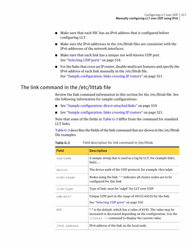
■ Make sure that each NIC has an IPv6 address that is configured beforeconfiguring LLT.
■ Make sure the IPv6 addresses in the /etc/llttab files are consistent with theIPv6 addresses of the network interfaces.
■ Make sure that each link has a unique not well-known UDP port.See “Selecting UDP ports” on page 518.
■ For the links that cross an IP router, disable multicast features and specify theIPv6 address of each link manually in the /etc/llttab file.See “Sample configuration: links crossing IP routers” on page 521.
The link command in the /etc/llttab fileReview the link command information in this section for the /etc/llttab file. Seethe following information for sample configurations:
■ See “Sample configuration: direct-attached links” on page 519.
■ See “Sample configuration: links crossing IP routers” on page 521.
Note that some of the fields in Table G-3 differ from the command for standardLLT links.
Table G-3 describes the fields of the link command that are shown in the /etc/llttabfile examples.
Table G-3 Field description for link command in /etc/llttab
DescriptionField
A unique string that is used as a tag by LLT; for example link1,link2,....
tag-name
The device path of the UDP protocol; for example /dev/udp6.device
Nodes using the link. "-" indicates all cluster nodes are to beconfigured for this link.
node-range
Type of link; must be "udp6" for LLT over UDP.link-type
Unique UDP port in the range of 49152-65535 for the link.
See “Selecting UDP ports” on page 518.
udp-port
"-" is the default, which has a value of 8192. The value may beincreased or decreased depending on the configuration. Use thelltstat -l command to display the current value.
MTU
IPv6 address of the link on the local node.IPv6 address
517Configuring LLT over UDPManually configuring LLT over UDP using IPv6
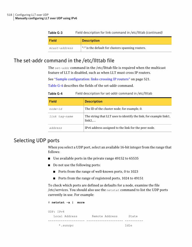
Table G-3 Field description for link command in /etc/llttab (continued)
DescriptionField
"-" is the default for clusters spanning routers.mcast-address
The set-addr command in the /etc/llttab fileThe set-addr command in the /etc/llttab file is required when the multicastfeature of LLT is disabled, such as when LLT must cross IP routers.
See “Sample configuration: links crossing IP routers” on page 521.
Table G-4 describes the fields of the set-addr command.
Table G-4 Field description for set-addr command in /etc/llttab
DescriptionField
The ID of the cluster node; for example, 0.node-id
The string that LLT uses to identify the link; for example link1,link2,....
link tag-name
IPv6 address assigned to the link for the peer node.address
Selecting UDP portsWhen you select a UDP port, select an available 16-bit integer from the range thatfollows:
■ Use available ports in the private range 49152 to 65535
■ Do not use the following ports:
■ Ports from the range of well-known ports, 0 to 1023
■ Ports from the range of registered ports, 1024 to 49151
To check which ports are defined as defaults for a node, examine the file/etc/services. You should also use the netstat command to list the UDP portscurrently in use. For example:
# netstat -a | more
UDP: IPv4
Local Address Remote Address State
-------------------- -------------------- ----------
*.sunrpc Idle
Configuring LLT over UDPManually configuring LLT over UDP using IPv6
518
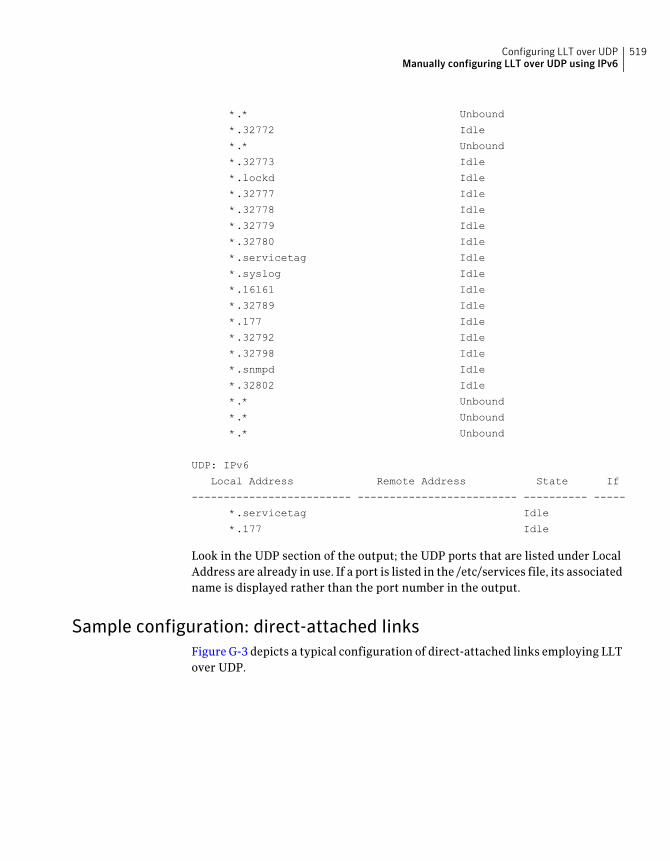
*.* Unbound
*.32772 Idle
*.* Unbound
*.32773 Idle
*.lockd Idle
*.32777 Idle
*.32778 Idle
*.32779 Idle
*.32780 Idle
*.servicetag Idle
*.syslog Idle
*.16161 Idle
*.32789 Idle
*.177 Idle
*.32792 Idle
*.32798 Idle
*.snmpd Idle
*.32802 Idle
*.* Unbound
*.* Unbound
*.* Unbound
UDP: IPv6
Local Address Remote Address State If
------------------------- ------------------------- ---------- -----
*.servicetag Idle
*.177 Idle
Look in the UDP section of the output; the UDP ports that are listed under LocalAddress are already in use. If a port is listed in the /etc/services file, its associatedname is displayed rather than the port number in the output.
Sample configuration: direct-attached linksFigure G-3 depicts a typical configuration of direct-attached links employing LLTover UDP.
519Configuring LLT over UDPManually configuring LLT over UDP using IPv6
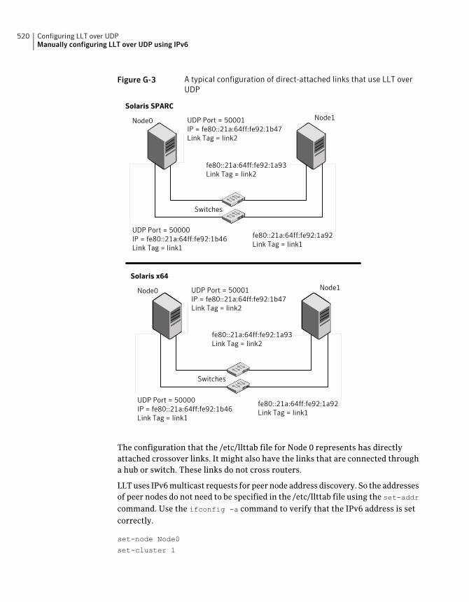
Figure G-3 A typical configuration of direct-attached links that use LLT overUDP
UDP Port = 50001IP = fe80::21a:64ff:fe92:1b47Link Tag = link2
UDP Port = 50000IP = fe80::21a:64ff:fe92:1b46Link Tag = link1
fe80::21a:64ff:fe92:1a93Link Tag = link2
fe80::21a:64ff:fe92:1a92Link Tag = link1
Switches
Node0 Node1
Solaris SPARC
Solaris x64
UDP Port = 50001IP = fe80::21a:64ff:fe92:1b47Link Tag = link2
UDP Port = 50000IP = fe80::21a:64ff:fe92:1b46Link Tag = link1
fe80::21a:64ff:fe92:1a93Link Tag = link2
fe80::21a:64ff:fe92:1a92Link Tag = link1
Switches
Node0 Node1
The configuration that the /etc/llttab file for Node 0 represents has directlyattached crossover links. It might also have the links that are connected througha hub or switch. These links do not cross routers.
LLT uses IPv6 multicast requests for peer node address discovery. So the addressesof peer nodes do not need to be specified in the /etc/llttab file using the set-addrcommand. Use the ifconfig -a command to verify that the IPv6 address is setcorrectly.
set-node Node0
set-cluster 1
Configuring LLT over UDPManually configuring LLT over UDP using IPv6
520
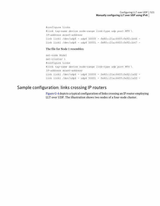
#configure Links
#link tag-name device node-range link-type udp port MTU \
IP-address mcast-address
link link1 /dev/udp6 - udp6 50000 - fe80::21a:64ff:fe92:1b46 -
link link1 /dev/udp6 - udp6 50001 - fe80::21a:64ff:fe92:1b47 -
The file for Node 1 resembles:
set-node Node1
set-cluster 1
#configure Links
#link tag-name device node-range link-type udp port MTU \
IP-address mcast-address
link link1 /dev/udp6 - udp6 50000 - fe80::21a:64ff:fe92:1a92 -
link link1 /dev/udp6 - udp6 50001 - fe80::21a:64ff:fe92:1a93 -
Sample configuration: links crossing IP routersFigure G-4 depicts a typical configuration of links crossing an IP router employingLLT over UDP. The illustration shows two nodes of a four-node cluster.
521Configuring LLT over UDPManually configuring LLT over UDP using IPv6
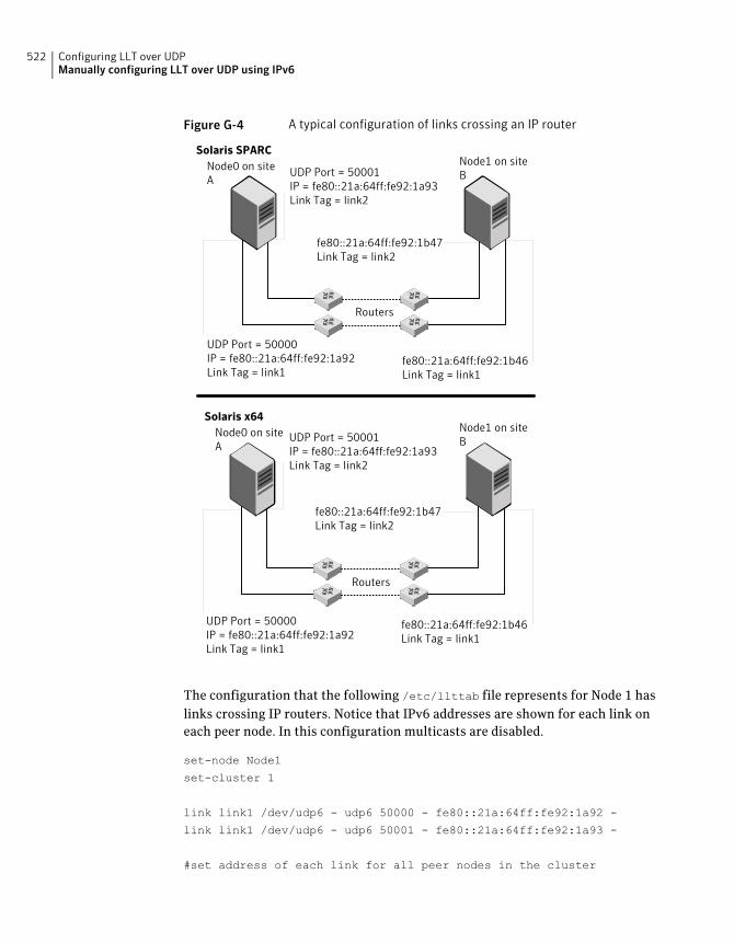
Figure G-4 A typical configuration of links crossing an IP router
UDP Port = 50001IP = fe80::21a:64ff:fe92:1a93Link Tag = link2
UDP Port = 50000IP = fe80::21a:64ff:fe92:1a92Link Tag = link1
fe80::21a:64ff:fe92:1b47Link Tag = link2
fe80::21a:64ff:fe92:1b46Link Tag = link1
Node0 on siteA
Node1 on siteB
Solaris SPARC
Solaris x64
UDP Port = 50001IP = fe80::21a:64ff:fe92:1a93Link Tag = link2
UDP Port = 50000IP = fe80::21a:64ff:fe92:1a92Link Tag = link1
fe80::21a:64ff:fe92:1b47Link Tag = link2
fe80::21a:64ff:fe92:1b46Link Tag = link1
Node0 on siteA
Node1 on siteB
Routers
Routers
The configuration that the following /etc/llttab file represents for Node 1 haslinks crossing IP routers. Notice that IPv6 addresses are shown for each link oneach peer node. In this configuration multicasts are disabled.
set-node Node1
set-cluster 1
link link1 /dev/udp6 - udp6 50000 - fe80::21a:64ff:fe92:1a92 -
link link1 /dev/udp6 - udp6 50001 - fe80::21a:64ff:fe92:1a93 -
#set address of each link for all peer nodes in the cluster
Configuring LLT over UDPManually configuring LLT over UDP using IPv6
522
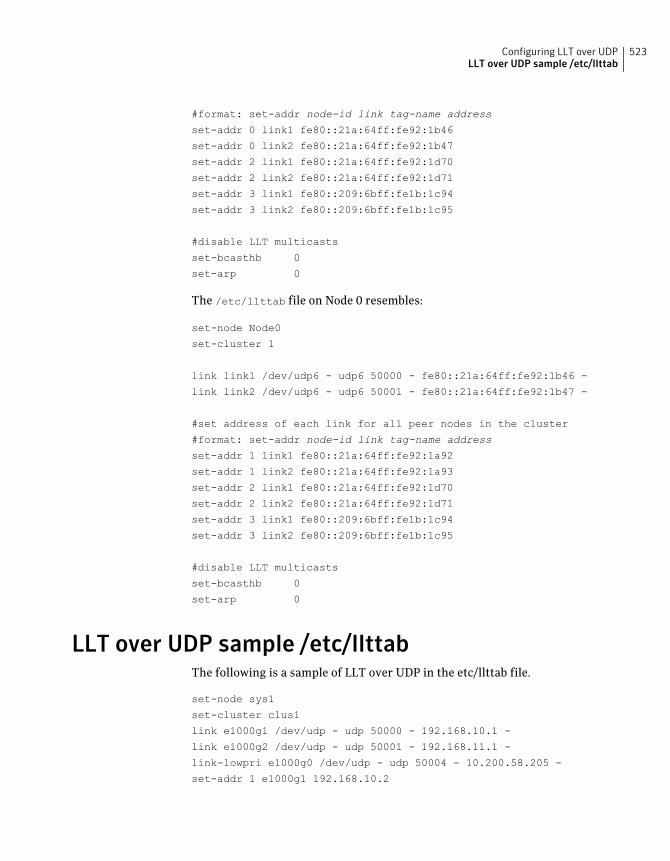
#format: set-addr node-id link tag-name address
set-addr 0 link1 fe80::21a:64ff:fe92:1b46
set-addr 0 link2 fe80::21a:64ff:fe92:1b47
set-addr 2 link1 fe80::21a:64ff:fe92:1d70
set-addr 2 link2 fe80::21a:64ff:fe92:1d71
set-addr 3 link1 fe80::209:6bff:fe1b:1c94
set-addr 3 link2 fe80::209:6bff:fe1b:1c95
#disable LLT multicasts
set-bcasthb 0
set-arp 0
The /etc/llttab file on Node 0 resembles:
set-node Node0
set-cluster 1
link link1 /dev/udp6 - udp6 50000 - fe80::21a:64ff:fe92:1b46 -
link link2 /dev/udp6 - udp6 50001 - fe80::21a:64ff:fe92:1b47 -
#set address of each link for all peer nodes in the cluster
#format: set-addr node-id link tag-name address
set-addr 1 link1 fe80::21a:64ff:fe92:1a92
set-addr 1 link2 fe80::21a:64ff:fe92:1a93
set-addr 2 link1 fe80::21a:64ff:fe92:1d70
set-addr 2 link2 fe80::21a:64ff:fe92:1d71
set-addr 3 link1 fe80::209:6bff:fe1b:1c94
set-addr 3 link2 fe80::209:6bff:fe1b:1c95
#disable LLT multicasts
set-bcasthb 0
set-arp 0
LLT over UDP sample /etc/llttabThe following is a sample of LLT over UDP in the etc/llttab file.
set-node sys1
set-cluster clus1
link e1000g1 /dev/udp - udp 50000 - 192.168.10.1 -
link e1000g2 /dev/udp - udp 50001 - 192.168.11.1 -
link-lowpri e1000g0 /dev/udp - udp 50004 - 10.200.58.205 -
set-addr 1 e1000g1 192.168.10.2
523Configuring LLT over UDPLLT over UDP sample /etc/llttab

set-addr 1 e1000g2 192.168.11.2
set-addr 1 e1000g0 10.200.58.206
set-bcasthb 0
set-arp 0
Configuring LLT over UDPLLT over UDP sample /etc/llttab
524
Configuring the secure shellor the remote shell forcommunications
This appendix includes the following topics:
■ Setting up inter-system communication
Setting up inter-system communicationIf you manually need to set up a communication mode, refer to these procedures.You must have root privilege to issue ssh or rsh commands on all systems in thecluster. If ssh is used to communicate between systems, it must be configured ina way such that it operates without requests for passwords or passphrases.Similarly, rsh must be configured in such a way to not prompt for passwords.
If system communication is not possible between systems using ssh or rsh, contactSymantec Support. See http://support.symantec.com.
Setting up ssh on cluster systemsUse the Secure Shell (ssh) to install VCS on all systems in a cluster from a systemoutside of the cluster. Before you start the installation process, verify that ssh isconfigured correctly.
Use Secure Shell (ssh) to do the following:
■ Log on to another system over a network
■ Execute commands on a remote system
■ Copy files from one system to another
HAppendix
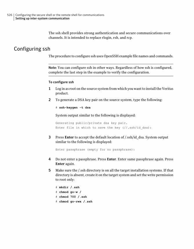
The ssh shell provides strong authentication and secure communications overchannels. It is intended to replace rlogin, rsh, and rcp.
Configuring sshThe procedure to configure ssh uses OpenSSH example file names and commands.
Note: You can configure ssh in other ways. Regardless of how ssh is configured,complete the last step in the example to verify the configuration.
To configure ssh
1 Log in as root on the source system from which you want to install the Veritasproduct.
2 To generate a DSA key pair on the source system, type the following:
# ssh-keygen -t dsa
System output similar to the following is displayed:
Generating public/private dsa key pair.
Enter file in which to save the key (//.ssh/id_dsa):
3 Press Enter to accept the default location of /.ssh/id_dsa. System outputsimilar to the following is displayed:
Enter passphrase (empty for no passphrase):
4 Do not enter a passphrase. Press Enter. Enter same passphrase again. PressEnter again.
5 Make sure the /.ssh directory is on all the target installation systems. If thatdirectory is absent, create it on the target system and set the write permissionto root only:
# mkdir /.ssh
# chmod go-w /
# chmod 700 /.ssh
# chmod go-rwx /.ssh
Configuring the secure shell or the remote shell for communicationsSetting up inter-system communication
526
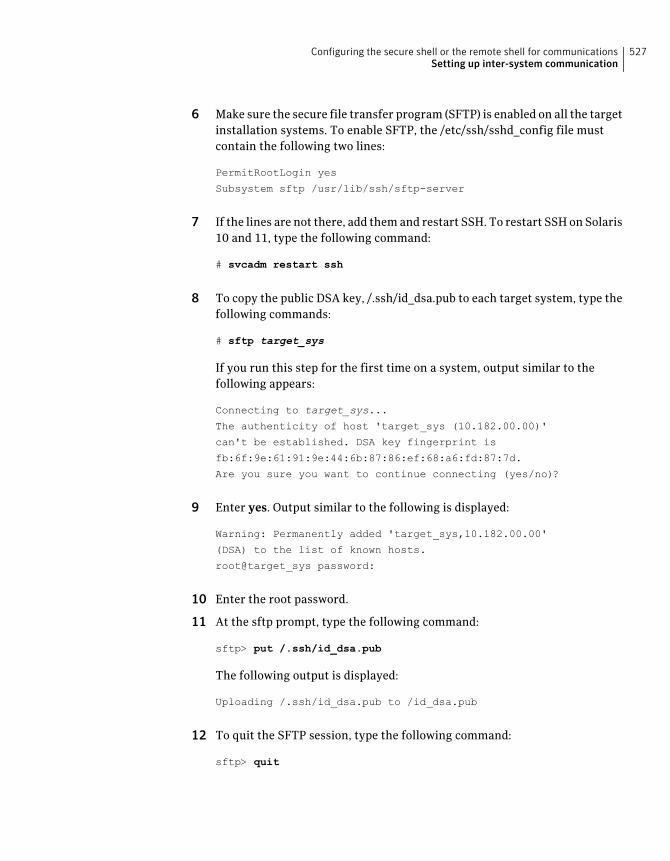
6 Make sure the secure file transfer program (SFTP) is enabled on all the targetinstallation systems. To enable SFTP, the /etc/ssh/sshd_config file mustcontain the following two lines:
PermitRootLogin yes
Subsystem sftp /usr/lib/ssh/sftp-server
7 If the lines are not there, add them and restart SSH. To restart SSH on Solaris10 and 11, type the following command:
# svcadm restart ssh
8 To copy the public DSA key, /.ssh/id_dsa.pub to each target system, type thefollowing commands:
# sftp target_sys
If you run this step for the first time on a system, output similar to thefollowing appears:
Connecting to target_sys...
The authenticity of host 'target_sys (10.182.00.00)'
can't be established. DSA key fingerprint is
fb:6f:9e:61:91:9e:44:6b:87:86:ef:68:a6:fd:87:7d.
Are you sure you want to continue connecting (yes/no)?
9 Enter yes. Output similar to the following is displayed:
Warning: Permanently added 'target_sys,10.182.00.00'
(DSA) to the list of known hosts.
root@target_sys password:
10 Enter the root password.
11 At the sftp prompt, type the following command:
sftp> put /.ssh/id_dsa.pub
The following output is displayed:
Uploading /.ssh/id_dsa.pub to /id_dsa.pub
12 To quit the SFTP session, type the following command:
sftp> quit
527Configuring the secure shell or the remote shell for communicationsSetting up inter-system communication
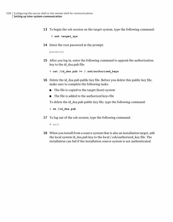
13 To begin the ssh session on the target system, type the following command:
# ssh target_sys
14 Enter the root password at the prompt:
password:
15 After you log in, enter the following command to append the authorizationkey to the id_dsa.pub file:
# cat /id_dsa.pub >> /.ssh/authorized_keys
16 Delete the id_dsa.pub public key file. Before you delete this public key file,make sure to complete the following tasks:
■ The file is copied to the target (host) system
■ The file is added to the authorized keys file
To delete the id_dsa.pub public key file, type the following command:
# rm /id_dsa.pub
17 To log out of the ssh session, type the following command:
# exit
18 When you install from a source system that is also an installation target, addthe local system id_dsa.pub key to the local /.ssh/authorized_key file. Theinstallation can fail if the installation source system is not authenticated.
Configuring the secure shell or the remote shell for communicationsSetting up inter-system communication
528
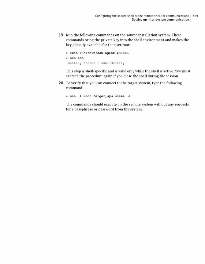
19 Run the following commands on the source installation system. Thesecommands bring the private key into the shell environment and makes thekey globally available for the user root:
# exec /usr/bin/ssh-agent $SHELL
# ssh-add
Identity added: /.ssh/identity
This step is shell-specific and is valid only while the shell is active. You mustexecute the procedure again if you close the shell during the session.
20 To verify that you can connect to the target system, type the followingcommand:
# ssh -l root target_sys uname -a
The commands should execute on the remote system without any requestsfor a passphrase or password from the system.
529Configuring the secure shell or the remote shell for communicationsSetting up inter-system communication

Configuring the secure shell or the remote shell for communicationsSetting up inter-system communication
530
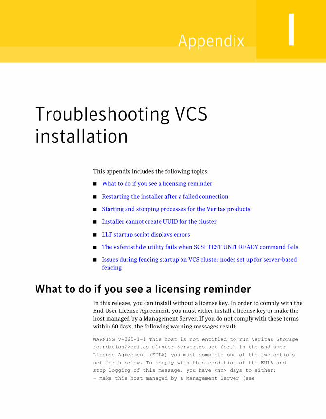
Troubleshooting VCSinstallation
This appendix includes the following topics:
■ What to do if you see a licensing reminder
■ Restarting the installer after a failed connection
■ Starting and stopping processes for the Veritas products
■ Installer cannot create UUID for the cluster
■ LLT startup script displays errors
■ The vxfentsthdw utility fails when SCSI TEST UNIT READY command fails
■ Issues during fencing startup on VCS cluster nodes set up for server-basedfencing
What to do if you see a licensing reminderIn this release, you can install without a license key. In order to comply with theEnd User License Agreement, you must either install a license key or make thehost managed by a Management Server. If you do not comply with these termswithin 60 days, the following warning messages result:
WARNING V-365-1-1 This host is not entitled to run Veritas Storage
Foundation/Veritas Cluster Server.As set forth in the End User
License Agreement (EULA) you must complete one of the two options
set forth below. To comply with this condition of the EULA and
stop logging of this message, you have <nn> days to either:
- make this host managed by a Management Server (see
IAppendix
http://go.symantec.com/sfhakeyless for details and free download),
or
- add a valid license key matching the functionality in use on this host
using the command 'vxlicinst'
To comply with the terms of the EULA, and remove these messages, you must doone of the following within 60 days:
■ Install a valid license key corresponding to the functionality in use on the host.After you install the license key, you must validate the license key using thefollowing command:
# /opt/VRTS/bin/vxlicrep
■ Continue with keyless licensing by managing the server or cluster with amanagement server.For more information about keyless licensing, see the following URL:http://go.symantec.com/sfhakeyless
Restarting the installer after a failed connectionIf an installation is killed because of a failed connection, you can restart theinstaller to resume the installation. The installer detects the existing installation.The installer prompts you whether you want to resume the installation. If youresume the installation, the installation proceeds from the point where theinstallation failed.
Starting and stopping processes for the Veritasproducts
After the installation and configuration is complete, the Veritas product installerstarts the processes that are used by the installed products. You can use theproduct installer to stop or start the processes, if required.
Troubleshooting VCS installationRestarting the installer after a failed connection
532
To stop the processes
◆ Use the -stop option to stop the product installation script.
For example, to stop the product's processes, enter the following command:
# ./installer -stop
or
# /opt/VRTS/install/installvcs program<version> -stop
Where <version> is the specific release version.
See “About the Veritas installer” on page 46.
To start the processes
◆ Use the -start option to start the product installation script.
For example, to start the product's processes, enter the following command:
# ./installer -start
or
# /opt/VRTS/install/installvcs program<version> -start
Where <version> is the specific release version.
See “About the Veritas installer” on page 46.
Installer cannot create UUID for the clusterThe installer displays the following error message if the installer cannot find theuuidconfig.pl script before it configures the UUID for the cluster:
Couldn't find uuidconfig.pl for uuid configuration,
please create uuid manually before start vcs
You may see the error message during VCS configuration, upgrade, or when youadd a node to the cluster using the installer.
Workaround: To start VCS, you must run the uuidconfig.pl script manually toconfigure the UUID on each cluster node.
533Troubleshooting VCS installationInstaller cannot create UUID for the cluster
To configure the cluster UUID when you create a cluster manually
◆ On one node in the cluster, perform the following command to populate thecluster UUID on each node in the cluster.
# /opt/VRTSvcs/bin/uuidconfig.pl -clus -configure nodeA
nodeB ... nodeN
Where nodeA, nodeB, through nodeN are the names of the cluster nodes.
LLT startup script displays errorsIf more than one system on the network has the same clusterid-nodeid pair andthe same Ethernet sap/UDP port, then the LLT startup script displays errormessages similar to the following:
LLT lltconfig ERROR V-14-2-15238 node 1 already exists
in cluster 8383 and has the address - 00:18:8B:E4:DE:27
LLT lltconfig ERROR V-14-2-15241 LLT not configured,
use -o to override this warning
LLT lltconfig ERROR V-14-2-15664 LLT could not
configure any link
LLT lltconfig ERROR V-14-2-15245 cluster id 1 is
already being used by nid 0 and has the
address - 00:04:23:AC:24:2D
LLT lltconfig ERROR V-14-2-15664 LLT could not
configure any link
Check the log files that get generated in the /var/svc/logdirectory for any errors.
Recommended action: Ensure that all systems on the network have uniqueclusterid-nodeid pair. You can use the lltdump -f device -D command to getthe list of unique clusterid-nodeid pairs connected to the network. This utility isavailable only for LLT-over-ethernet.
The vxfentsthdw utility fails when SCSI TEST UNITREADY command fails
While running the vxfentsthdw utility, you may see a message that resembles asfollows:
Issuing SCSI TEST UNIT READY to disk reserved by other node
FAILED.
Troubleshooting VCS installationLLT startup script displays errors
534
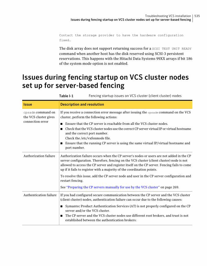
Contact the storage provider to have the hardware configuration
fixed.
The disk array does not support returning success for a SCSI TEST UNIT READY
command when another host has the disk reserved using SCSI-3 persistentreservations. This happens with the Hitachi Data Systems 99XX arrays if bit 186of the system mode option is not enabled.
Issues during fencing startup on VCS cluster nodesset up for server-based fencing
Table I-1 Fencing startup issues on VCS cluster (client cluster) nodes
Description and resolutionIssue
If you receive a connection error message after issuing the cpsadm command on the VCScluster, perform the following actions:
■ Ensure that the CP server is reachable from all the VCS cluster nodes.
■ Check that the VCS cluster nodes use the correct CP server virtual IP or virtual hostnameand the correct port number.
Check the /etc/vxfenmode file.
■ Ensure that the running CP server is using the same virtual IP/virtual hostname andport number.
cpsadm command onthe VCS cluster givesconnection error
Authorization failure occurs when the CP server's nodes or users are not added in the CPserver configuration. Therefore, fencing on the VCS cluster (client cluster) node is notallowed to access the CP server and register itself on the CP server. Fencing fails to comeup if it fails to register with a majority of the coordination points.
To resolve this issue, add the CP server node and user in the CP server configuration andrestart fencing.
See “Preparing the CP servers manually for use by the VCS cluster” on page 269.
Authorization failure
If you had configured secure communication between the CP server and the VCS cluster(client cluster) nodes, authentication failure can occur due to the following causes:
■ Symantec Product Authentication Services (AT) is not properly configured on the CPserver and/or the VCS cluster.
■ The CP server and the VCS cluster nodes use different root brokers, and trust is notestablished between the authentication brokers:
Authentication failure
535Troubleshooting VCS installationIssues during fencing startup on VCS cluster nodes set up for server-based fencing

Troubleshooting VCS installationIssues during fencing startup on VCS cluster nodes set up for server-based fencing
536
Sample VCS cluster setupdiagrams for CPserver-based I/O fencing
This appendix includes the following topics:
■ Configuration diagrams for setting up server-based I/O fencing
Configuration diagrams for setting up server-basedI/O fencing
The following CP server configuration diagrams can be used as guides when settingup CP server within your configuration:
■ Two unique client clusters that are served by 3 CP servers:See Figure J-1 on page 538.
■ Client cluster that is served by highly available CP server and 2 SCSI-3 disks:
■ Two node campus cluster that is served be remote CP server and 2 SCSI-3 disks:
■ Multiple client clusters that are served by highly available CP server and 2SCSI-3 disks:
Two unique client clusters served by 3 CP serversFigure J-1 displays a configuration where two unique client clusters are beingserved by 3 CP servers (coordination points). Each client cluster has its own uniqueuser ID (UUID1 and UUID2).
JAppendix
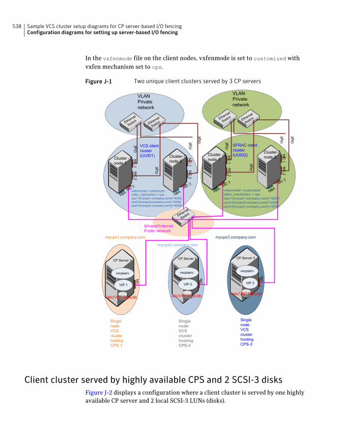
In the vxfenmode file on the client nodes, vxfenmode is set to customized withvxfen mechanism set to cps.
Figure J-1 Two unique client clusters served by 3 CP servers
NIC
1
Cluster -1node 1
NIC
2
NIC
1
Cluster-1node 2
NIC
2
Ethern
et
Switch Eth
ernet
Switch
NIC
1
Cluster -2node 1
NIC
2
NIC
1
Cluster-2node 2
NIC
2
Ethern
et
Switch Eth
ernet
Switch
NIC
CP Server 1
Ethern
et
Switch
Intranet/InternetPublic network
CP Server 2
NIC
CP Server 3
NIC
NIC3 NIC
3 NIC3 NIC
3
VCS clientcluster(UUID1)
SFRAC clientcluster(UUID2)
SinglenodeVCSclusterhostingCPS-1
SinglenodeVCSclusterhostingCPS-2
SinglenodeVCSclusterhostingCPS-3
/etc/VRTScps/db/etc/VRTScps/db/etc/VRTScps/db
vxcpserv
VIP 1
vxcpserv
VIP 2
vxcpserv
VIP 3
HBA
HBA HB
A
HBA
GigE
GigE
GigE
GigE GigE
GigE
GigE
GigE
VLANPrivatenetwork
VLANPrivatenetwork
mycps1.company.com
mycps2.company.com
mycps3.company.com
vxfenmode= customizedvxfen_mechanism = cpscps1=[mycps1.company.com]=14250cps2=[mycps2company.com]=14250cps3=[mycps3.company.com]=14250
vxfenmode= customizedvxfen_mechanism = cpscps1=[mycps1.company.com]=14250cps2=[mycps2company.com]=14250cps3=[mycps3.company.com]=14250
Client cluster served by highly available CPS and 2 SCSI-3 disksFigure J-2 displays a configuration where a client cluster is served by one highlyavailable CP server and 2 local SCSI-3 LUNs (disks).
Sample VCS cluster setup diagrams for CP server-based I/O fencingConfiguration diagrams for setting up server-based I/O fencing
538
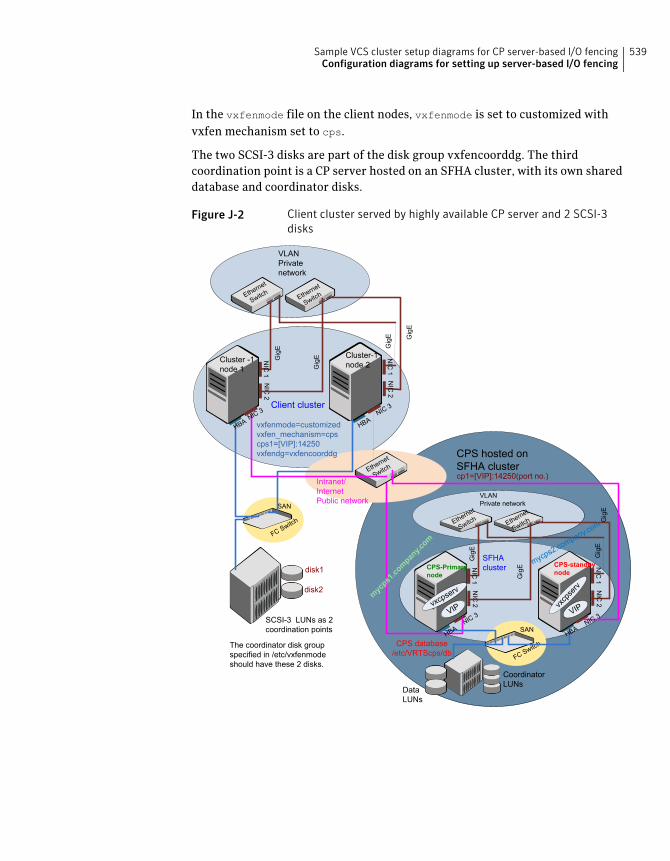
In the vxfenmode file on the client nodes, vxfenmode is set to customized withvxfen mechanism set to cps.
The two SCSI-3 disks are part of the disk group vxfencoorddg. The thirdcoordination point is a CP server hosted on an SFHA cluster, with its own shareddatabase and coordinator disks.
Figure J-2 Client cluster served by highly available CP server and 2 SCSI-3disks
SAN
FCSw
itch
CPS database/etc/VRTScps/db
NIC
1
Cluster -1node 1
NIC
2
NIC
1
Cluster-1node 2
NIC
2
Ethern
et
Switch Eth
ernet
Switch
VLANPrivatenetwork
Ethern
et
Switch
Intranet/InternetPublic network
NIC3 NIC
3Client cluster
NIC
1
CPS-Primarynode
NIC
2
NIC
1
CPS-standbynode
NIC
2
Ethern
et
Switch Eth
ernet
Switch
VLANPrivate network
NIC3
NIC3
SFHAcluster
VIPvxc
pserv
vxcpserv
VIP
DataLUNs
CoordinatorLUNs
SAN
FCSw
itch
SCSI-3 LUNs as 2coordination points
disk1
disk2
CPS hosted onSFHA clustercp1=[VIP]:14250(port no.)
HBA HB
A
HBA
HBA
GigE
GigE
GigE GigE
GigE
GigE
GigE
GigE
mycps1.company.com
mycps
2.com
pany.co
m
vxfenmode=customizedvxfen_mechanism=cpscps1=[VIP]:14250vxfendg=vxfencoorddg
The coordinator disk groupspecified in /etc/vxfenmodeshould have these 2 disks.
539Sample VCS cluster setup diagrams for CP server-based I/O fencingConfiguration diagrams for setting up server-based I/O fencing
Two node campus cluster served by remote CP server and 2 SCSI-3disks
Figure J-3 displays a configuration where a two node campus cluster is beingserved by one remote CP server and 2 local SCSI-3 LUN (disks).
In the vxfenmode file on the client nodes, vxfenmode is set to customized withvxfen mechanism set to cps.
The two SCSI-3 disks (one from each site) are part of disk group vxfencoorddg.The third coordination point is a CP server on a single node VCS cluster.
Sample VCS cluster setup diagrams for CP server-based I/O fencingConfiguration diagrams for setting up server-based I/O fencing
540
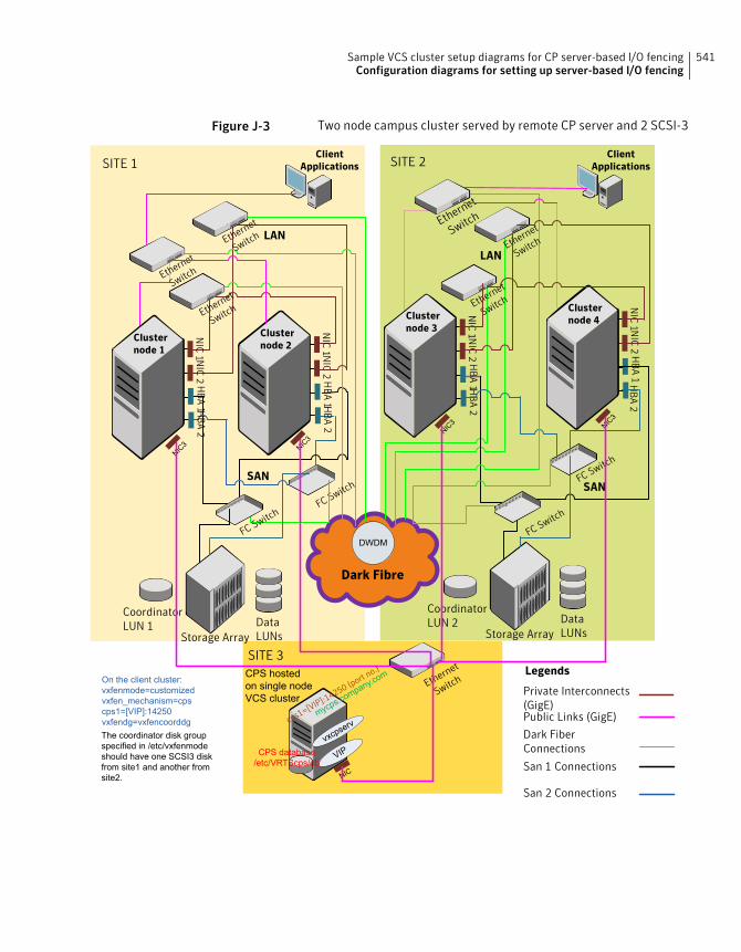
Figure J-3 Two node campus cluster served by remote CP server and 2 SCSI-3
LAN
LAN
Dark Fibre
SITE 1 SITE 2
SITE 3
NIC
1 NIC
2H
BA
2H
BA
1
Clusternode 1
NIC
1 NIC
2H
BA
2H
BA
1
Clusternode 2
NIC
1 NIC
2H
BA
2H
BA
1
Clusternode 3
NIC
1 NIC
2H
BA
2H
BA
1
Clusternode 4
ClientApplications
ClientApplications
Ethernet
Switch
Ethernet
Switch
Ethernet
Switch
Ethernet
Switch
Ethernet
Switch
Ethernet
Switch
FC SwitchFC Switch
FC Switch
FC Switch
CoordinatorLUN 1 Data
LUNsStorage Array
CoordinatorLUN 2 Data
LUNsStorage Array
DWDM
Private Interconnects(GigE)
San 2 Connections
Legends
Dark FiberConnections
San 1 Connections
Public Links (GigE)
SANSAN
CPS hostedon single nodeVCS cluster
NIC
VIPvxc
pserv
CPS database/etc/VRTScps/db
mycps
.comp
any.com
Ethernet
Switch
NIC3 NI
C3
cps1=[VIP]:14250 (port no.)
NIC3 NI
C3
The coordinator disk groupspecified in /etc/vxfenmodeshould have one SCSI3 diskfrom site1 and another fromsite2.
On the client cluster:vxfenmode=customizedvxfen_mechanism=cpscps1=[VIP]:14250vxfendg=vxfencoorddg
541Sample VCS cluster setup diagrams for CP server-based I/O fencingConfiguration diagrams for setting up server-based I/O fencing
Multiple client clusters served by highly available CP server and 2SCSI-3 disks
Figure J-4 displays a configuration where multiple client clusters are being servedby one highly available CP server and 2 local SCSI-3 LUNS (disks).
In the vxfenmode file on the client nodes, vxfenmode is set to customized withvxfen mechanism set to cps.
The two SCSI-3 disks are are part of the disk group vxfencoorddg. The thirdcoordination point is a CP server, hosted on an SFHA cluster, with its own shareddatabase and coordinator disks.
Sample VCS cluster setup diagrams for CP server-based I/O fencingConfiguration diagrams for setting up server-based I/O fencing
542
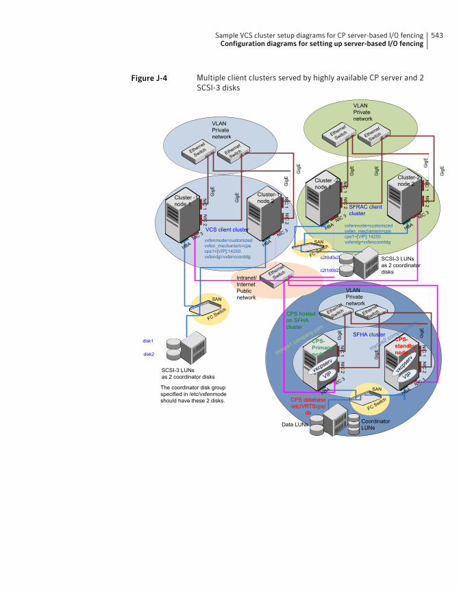
Figure J-4 Multiple client clusters served by highly available CP server and 2SCSI-3 disks
CPS database/etc/VRTScps/
db
NIC
1
Cluster -1node 1
NIC
2
NIC
1
Cluster-1node 2
NIC
2
Ethern
et
Switch Eth
ernet
Switch
VLANPrivatenetwork
Ethern
et
SwitchIntranet/
InternetPublicnetwork
NIC3 NIC
3VCS client cluster
NIC
1
CPS-Primarynode
NIC
2
NIC
1
CPS-standbynode
NIC
2
Ethern
et
Switch Eth
ernet
Switch
VLANPrivatenetwork
NIC3
NIC3
SFHA cluster
VIPvxc
pserv
vxcpserv
VIP
Data LUNs CoordinatorLUNs
SAN
FCSw
itch
SCSI-3 LUNsas 2 coordinator disks
SAN
FCSw
itch
disk1
disk2
NIC
1
Cluster -2node 1
NIC
2
NIC
1
Cluster-2node 2
NIC
2
Ethern
et
Switch Eth
ernet
Switch
VLANPrivatenetwork
NIC3 NIC
3SFRAC clientcluster
SAN
FCSw
itch
c2t0d0s2
c2t1d0s2
CPS hostedon SFHAcluster
HBA HB
A
HBA
HBA
HBA
HBA
SCSI-3 LUNsas 2 coordinatordisks
GigE
GigE
GigE
GigE
GigE
GigE
GigEGigE
GigE
GigE
GigE
mycps
1.com
pany.co
m
mycps
2.com
pany.co
m
vxfenmode=customizedvxfen_mechanism=cpscps1=[VIP]:14250vxfendg=vxfencoorddg
vxfenmode=customizedvxfen_mechanism=cpscps1=[VIP]:14250vxfendg=vxfencoorddg
The coordinator disk groupspecified in /etc/vxfenmodeshould have these 2 disks.
543Sample VCS cluster setup diagrams for CP server-based I/O fencingConfiguration diagrams for setting up server-based I/O fencing

Sample VCS cluster setup diagrams for CP server-based I/O fencingConfiguration diagrams for setting up server-based I/O fencing
544
Reconciling major/minornumbers for NFS shareddisks
This appendix includes the following topics:
■ Reconciling major/minor numbers for NFS shared disks
Reconciling major/minor numbers for NFS shareddisks
Your configuration may include disks on the shared bus that support NFS. Youcan configure the NFS file systems that you export on disk partitions or on VeritasVolume Manager volumes.
An example disk partition name is /dev/dsk/c1t1d0s2.
An example volume name is/dev/vx/dsk/shareddg/vol3. Each name representsthe block device on which the file system is to be mounted.
In a VCS cluster, block devices providing NFS service must have the same majorand minor numbers on each cluster node. Major numbers identify required devicedrivers (such as a Solaris partition or a VxVM volume). Minor numbers identifythe specific devices themselves. NFS also uses major and minor numbers to identifythe exported file system.
Major and minor numbers must be verified to ensure that the NFS identity forthe file system is the same when exported from each node.
KAppendix
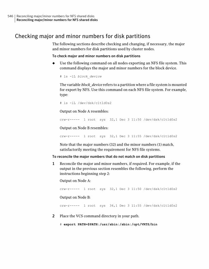
Checking major and minor numbers for disk partitionsThe following sections describe checking and changing, if necessary, the majorand minor numbers for disk partitions used by cluster nodes.
To check major and minor numbers on disk partitions
◆ Use the following command on all nodes exporting an NFS file system. Thiscommand displays the major and minor numbers for the block device.
# ls -lL block_device
The variable block_device refers to a partition where a file system is mountedfor export by NFS. Use this command on each NFS file system. For example,type:
# ls -lL /dev/dsk/c1t1d0s2
Output on Node A resembles:
crw-r----- 1 root sys 32,1 Dec 3 11:50 /dev/dsk/c1t1d0s2
Output on Node B resembles:
crw-r----- 1 root sys 32,1 Dec 3 11:55 /dev/dsk/c1t1d0s2
Note that the major numbers (32) and the minor numbers (1) match,satisfactorily meeting the requirement for NFS file systems.
To reconcile the major numbers that do not match on disk partitions
1 Reconcile the major and minor numbers, if required. For example, if theoutput in the previous section resembles the following, perform theinstructions beginning step 2:
Output on Node A:
crw-r----- 1 root sys 32,1 Dec 3 11:50 /dev/dsk/c1t1d0s2
Output on Node B:
crw-r----- 1 root sys 36,1 Dec 3 11:55 /dev/dsk/c1t1d0s2
2 Place the VCS command directory in your path.
# export PATH=$PATH:/usr/sbin:/sbin:/opt/VRTS/bin
Reconciling major/minor numbers for NFS shared disksReconciling major/minor numbers for NFS shared disks
546

3 Attempt to change the major number on System B (now 36) to match that ofSystem A (32). Use the command:
# haremajor -sd major_number
For example, on Node B, enter:
# haremajor -sd 32
4 If the command succeeds, go to step 8.
5 If the command fails, you may see a message resembling:
Error: Preexisting major number 32
These are available numbers on this system: 128...
Check /etc/name_to_major on all systems for
available numbers.
6 Notice that the number 36 (the major number on Node A) is not available onNode B. Run the haremajor command on Node B and change it to 128,
# haremajor -sd 128
7 Run the same command on Node A. If the command fails on Node A, theoutput lists the available numbers. Rerun the command on both nodes, settingthe major number to one available to both.
8 Reboot each system on which the command succeeds.
9 Proceed to reconcile the major numbers for your next partition.
To reconcile the minor numbers that do not match on disk partitions
1 In the example, the minor numbers are 1 and 3 and are reconciled by settingto 30 on each node.
2 Type the following command on both nodes using the name of the blockdevice:
# ls -1 /dev/dsk/c1t1d0s2
Output from this command resembles the following on Node A:
lrwxrwxrwx 1 root root 83 Dec 3 11:50
/dev/dsk/c1t1d0s2 -> ../../
devices/sbus@1f,0/QLGC,isp@0,10000/sd@1,0:d,raw
The device name (in bold) includes the slash following the word devices,and continues to, but does not include, the colon.
547Reconciling major/minor numbers for NFS shared disksReconciling major/minor numbers for NFS shared disks
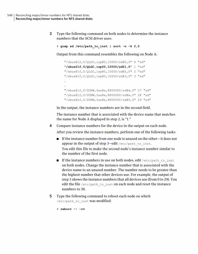
3 Type the following command on both nodes to determine the instancenumbers that the SCSI driver uses:
# grep sd /etc/path_to_inst | sort -n -k 2,2
Output from this command resembles the following on Node A:
"/sbus@1f,0/QLGC,isp@0,10000/sd@0,0" 0 "sd"
"/sbus@1f,0/QLGC,isp@0,10000/sd@1,0" 1 "sd"
"/sbus@1f,0/QLGC,isp@0,10000/sd@2,0" 2 "sd"
"/sbus@1f,0/QLGC,isp@0,10000/sd@3,0" 3 "sd"
.
.
"/sbus@1f,0/SUNW,fas@e,8800000/sd@d,0" 27 "sd"
"/sbus@1f,0/SUNW,fas@e,8800000/sd@e,0" 28 "sd"
"/sbus@1f,0/SUNW,fas@e,8800000/sd@f,0" 29 "sd"
In the output, the instance numbers are in the second field.
The instance number that is associated with the device name that matchesthe name for Node A displayed in step 2, is "1."
4 Compare instance numbers for the device in the output on each node.
After you review the instance numbers, perform one of the following tasks:
■ If the instance number from one node is unused on the other— it does notappear in the output of step 3—edit /etc/path_to_inst.
You edit this file to make the second node’s instance number similar tothe number of the first node.
■ If the instance numbers in use on both nodes, edit /etc/path_to_inston both nodes. Change the instance number that is associated with thedevice name to an unused number. The number needs to be greater thanthe highest number that other devices use. For example, the output ofstep 3 shows the instance numbers that all devices use (from 0 to 29). Youedit the file /etc/path_to_inst on each node and reset the instancenumbers to 30.
5 Type the following command to reboot each node on which/etc/path_to_inst was modified:
# reboot -- -rv
Reconciling major/minor numbers for NFS shared disksReconciling major/minor numbers for NFS shared disks
548

Checking the major and minor number for VxVM volumesThe following sections describe checking and changing, if necessary, the majorand minor numbers for the VxVM volumes that cluster systems use.
To check major and minor numbers on VxVM volumes
1 Place the VCS command directory in your path. For example:
# export PATH=$PATH:/usr/sbin:/sbin:/opt/VRTS/bin
2 To list the devices, use the ls -lL block_device command on each node:
# ls -lL /dev/vx/dsk/shareddg/vol3
On Node A, the output may resemble:
brw------- 1 root root 32,43000 Mar 22 16:4 1
/dev/vx/dsk/shareddg/vol3
On Node B, the output may resemble:
brw------- 1 root root 36,43000 Mar 22 16:4 1
/dev/vx/dsk/shareddg/vol3
3 Import the associated shared disk group on each node.
549Reconciling major/minor numbers for NFS shared disksReconciling major/minor numbers for NFS shared disks
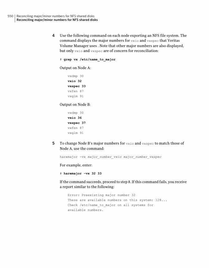
4 Use the following command on each node exporting an NFS file system. Thecommand displays the major numbers for vxio and vxspec that VeritasVolume Manager uses . Note that other major numbers are also displayed,but only vxio and vxspec are of concern for reconciliation:
# grep vx /etc/name_to_major
Output on Node A:
vxdmp 30
vxio 32
vxspec 33
vxfen 87
vxglm 91
Output on Node B:
vxdmp 30
vxio 36
vxspec 37
vxfen 87
vxglm 91
5 To change Node B’s major numbers for vxio and vxspec to match those ofNode A, use the command:
haremajor -vx major_number_vxio major_number_vxspec
For example, enter:
# haremajor -vx 32 33
If the command succeeds, proceed to step 8. If this command fails, you receivea report similar to the following:
Error: Preexisting major number 32
These are available numbers on this system: 128...
Check /etc/name_to_major on all systems for
available numbers.
Reconciling major/minor numbers for NFS shared disksReconciling major/minor numbers for NFS shared disks
550
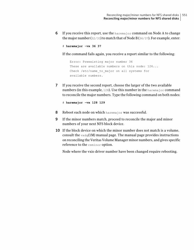
6 If you receive this report, use the haremajor command on Node A to changethe major number (32/33) to match that of Node B (36/37). For example, enter:
# haremajor -vx 36 37
If the command fails again, you receive a report similar to the following:
Error: Preexisting major number 36
These are available numbers on this node: 126...
Check /etc/name_to_major on all systems for
available numbers.
7 If you receive the second report, choose the larger of the two availablenumbers (in this example, 128). Use this number in the haremajor commandto reconcile the major numbers. Type the following command on both nodes:
# haremajor -vx 128 129
8 Reboot each node on which haremajor was successful.
9 If the minor numbers match, proceed to reconcile the major and minornumbers of your next NFS block device.
10 If the block device on which the minor number does not match is a volume,consult the vxdg(1M) manual page. The manual page provides instructionson reconciling the Veritas Volume Manager minor numbers, and gives specificreference to the reminor option.
Node where the vxio driver number have been changed require rebooting.
551Reconciling major/minor numbers for NFS shared disksReconciling major/minor numbers for NFS shared disks

Reconciling major/minor numbers for NFS shared disksReconciling major/minor numbers for NFS shared disks
552
Compatability issues wheninstalling Veritas ClusterServer with other products
This appendix includes the following topics:
■ Installing, uninstalling, or upgrading Storage Foundation products when otherVeritas products are present
■ Installing, uninstalling, or upgrading Storage Foundation products when VOMis already present
■ Installing, uninstalling, or upgrading Storage Foundation products whenNetBackup is already present
Installing, uninstalling, or upgrading StorageFoundation products when other Veritas productsare present
Installing Storage Foundation when other Veritas products are installed can createcompatibility issues. For example, installing Storage Foundation products whenVOM, ApplicationHA, and NetBackup are present on the systems.
LAppendix
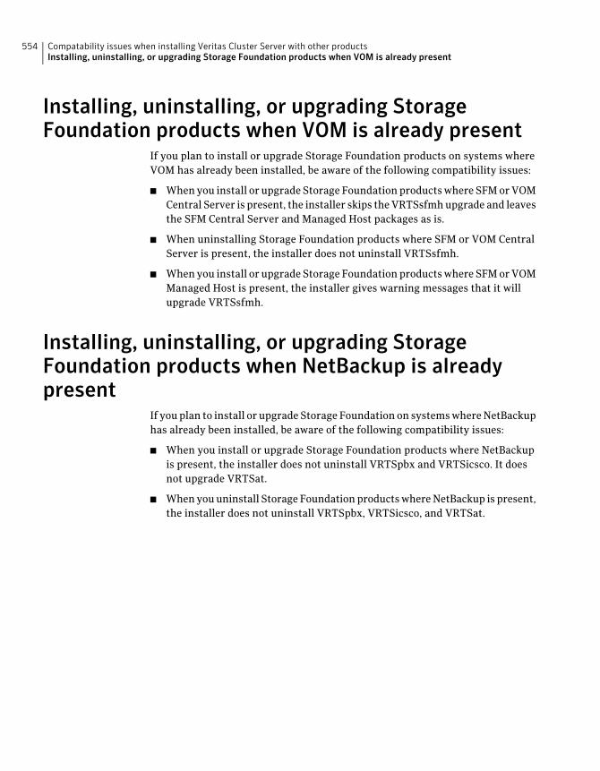
Installing, uninstalling, or upgrading StorageFoundation products when VOM is already present
If you plan to install or upgrade Storage Foundation products on systems whereVOM has already been installed, be aware of the following compatibility issues:
■ When you install or upgrade Storage Foundation products where SFM or VOMCentral Server is present, the installer skips the VRTSsfmh upgrade and leavesthe SFM Central Server and Managed Host packages as is.
■ When uninstalling Storage Foundation products where SFM or VOM CentralServer is present, the installer does not uninstall VRTSsfmh.
■ When you install or upgrade Storage Foundation products where SFM or VOMManaged Host is present, the installer gives warning messages that it willupgrade VRTSsfmh.
Installing, uninstalling, or upgrading StorageFoundation products when NetBackup is alreadypresent
If you plan to install or upgrade Storage Foundation on systems where NetBackuphas already been installed, be aware of the following compatibility issues:
■ When you install or upgrade Storage Foundation products where NetBackupis present, the installer does not uninstall VRTSpbx and VRTSicsco. It doesnot upgrade VRTSat.
■ When you uninstall Storage Foundation products where NetBackup is present,the installer does not uninstall VRTSpbx, VRTSicsco, and VRTSat.
Compatability issues when installing Veritas Cluster Server with other productsInstalling, uninstalling, or upgrading Storage Foundation products when VOM is already present
554
Symbols/etc/llttab
LLT directives 255
Aabort sequence 73about
global clusters 27adding
ClusterService group 262users 142
adding nodeto a one-node cluster 387
attributesUseFence 266
Bblock device
partitionsexample file name 545
volumesexample file name 545
bundled agentstypes.cf file 258
Ccables
cross-over Ethernet 400cluster
creating a single-node clusterinstaller 504manual 505
four-node configuration 24removing a node from 413verifying operation 379
Cluster Manager 29installing Java Console 367
ClusterService groupadding manually 262
cold startrunning VCS 26
commandsformat 71gabconfig 257, 377hastatus 379hastop 435hasys 379lltconfig 485lltstat 375vxdisksetup (initializing disks) 151vxlicinst 149–150, 236vxlicrep 148, 237
communication channels 25communication disk 25configuration files
types.cf 258configuring
GAB 257hardware 36LLT
manual 253private network 64rsh 67ssh 67, 525switches 64
configuring VCSadding users 142event notification 143–144global clusters 146required information 78script-based installer 128starting 129
controllersprivate Ethernet 64SCSI 68
coordinator disksDMP devices 32for I/O fencing 32setting up 264
creatingFlash archive 242
Index

creating (continued)post-deployment scripts 243
Ddata disks
for I/O fencing 32demo key 238directives
LLT 255disk space
directories 36language pack 36required 36
disksadding and initializing 151coordinator 264testing with vxfentsthdw 155verifying node access 156
documentationaccessing 364
Eeeprom
parameters 64Ethernet controllers 64, 400
FFC-AL controllers 71fibre channel 36flarcreate 242Flash archive 242
post-deployment scripts 243functions
go 73
GGAB
description 25manual configuration 257port membership information 377starting 261verifying 377
gabconfig command 257, 377-a (verifying GAB) 377
gabtab filecreating 257verifying after installation 485
global clusters 27configuration 146
Hhardware
configuration 24configuring network and storage 36
hastatus -summary command 379hastop command 435hasys -display command 379hubs 64
independent 400
II/O fencing
checking disks 155setting up 263shared storage 155
I/O fencing requirementsnon-SCSI-3 42
installer programuninstalling language packages 428
InstallingVCS with the Web-based installer 177
installingJumpStart 238language packages 93
manually 235manual 229post 147required disk space 36simulator 370
installing manuallyJapanese language packages 235
installing VCSrequired information 78
installvcsoptions 49
installvcs promptsb 49n 49y 49
JJapanese language packages 235Java Console 29
installing 367installing on UNIX 367
Index556
JumpStartinstalling 238
Llanguage packages 428
disk space 36Japanese 235
license keysadding with vxlicinst 149, 236obtaining 58replacing demo key 150, 238
licensesinformation about 148showing information 237
linksprivate network 485
Live Upgradepreparing 337upgrade paths 335upgrading Solaris on alternate boot disk 341
LLTdescription 25directives 255interconnects 75manual configuration 253starting 260verifying 375
LLT directiveslink 255link-lowpri 255set-cluster 255set-node 255
lltconfig command 485llthosts file
verifying after installation 485lltstat command 375llttab file
verifying after installation 485
MMAC addresses 64main.cf file
contents after installation 491main.cf files 496major and minor numbers
checking 546, 549shared devices 545
MANPATH variablesetting 73
manual installationpreparing 227
media speed 75optimizing 75
membership information 377mounting
software disc 76
Nnetwork partition
preexisting 26protecting against 24
Network partitionsprotecting against 25
network switches 64NFS 23NFS services
shared storage 545non-SCSI-3 fencing
manual configuration 281setting up 281
non-SCSI-3 I/O fencingrequirements 42
non-SCSI3 fencingsetting up 168using installvcs program 168
Ooptimizing
media speed 75overview
VCS 23
Pparameters
eeprom 64PATH variable
setting 73VCS commands 374
persistent reservationsSCSI-3 68
phased 301phased upgrade 301, 303
example 302port a
membership 377
557Index
port hmembership 377
port membership information 377post-deployment scripts 243preparing
Live Upgrade 337manual installation 227
prerequisitesuninstalling 425
private networkconfiguring 64
RRAM
installation requirement 36removing a system from a cluster 413requirements
Ethernet controllers 36fibre channel 36hardware 36RAM Ethernet controllers 36SCSI host bus adapter 36
response files 51rolling upgrade 330
versions 328rsh 129, 525
configuration 67
Sscript-based installer
VCS configuration overview 128SCSI driver
determining instance numbers 547SCSI host bus adapter 36SCSI-3
persistent reservations 68SCSI-3 persistent reservations
verifying 263seeding 26
automatic 26manual 26
settingMANPATH variable 73PATH variable 73
shared storageFibre Channel
setting up 71NFS services 545
simulatorinstalling 370
single-node clusteradding a node to 387
single-system clustercreating 504–505
SMTP email notification 143SNMP trap notification 144ssh 129, 525
configuration 67configuring 525
starting configurationinstallvcs program 129Veritas product installer 129
starting VCS after manual upgrade 260storage
fully shared vs. distributed 24setting up shared fibre 71shared 24
switches 64system communication using rsh
ssh 525system state attribute value 379
Ttypes.cf 258
bundled agents 258types.cf file 258
Uuninstalling
prerequisites 425uninstalling language packages 428upgrade
phased 301, 303upgrade paths
Live Upgrade 335SPARC 290x64 Platform Edition 290
upgradingphased 301rolling 330
using Live Upgrade 335
Vvariables
MANPATH 73PATH 73
Index558
VCSbasics 23command directory path variable 374configuration files
main.cf 489configuring 128coordinator disks 264documentation 364manually installing 229notifications 27replicated states on each system 24starting 260–261
VCS features 27VCS installation
verifyingcluster operations 374GAB operations 374LLT operations 374
VCS notificationsSMTP notification 27SNMP notification 27
Veritas Operations Manager 29Volume Manager
Fibre Channel 71vxdisksetup command 151vxlicinst command 149, 236vxlicrep command 148, 237
WWeb-based installer 177
559Index


