Vermont Agency of Transportation Program Development Division Materials and Research Section To: Joshua Schultz, Project Manager – VTrans’ Highway Safety & Design Section From: Thomas D. Eliassen, P.G., Transportation Geologist and Chad A. Allen, P.E., Geotechnical Engineer via Christopher C. Benda, P.E., Soils and Foundations Engineer Date: September 19, 2012 Subject: COLCHESTER HES NH 5600(14), US 2 & 7, I-89 EXIT 16 REQUEST FOR BORINGS & WALL RECOMMENDATIONS 1.0 INTRODUCTION We have completed our initial geotechnical investigation for the Colchester HES NH 5600(14) project. The project is located along Route US 2 & US 7 between the intersection of Highpoint Center /South Park Drive Intersection and the Rathe Road/Champlain Drive Intersection in Colchester. The project will consist of the construction of a double diamond interchange with I-89 and the installation of mast arms for controlling traffic along the project route. In addition, the construction of three retaining walls is proposed. One wall will be located along Lower Mountain View Drive and the other two walls will be constructed adjacent to shared use paths on either side of US 2 & US 7, beneath I-89, at Interchange 16. This report summarizes the boring and lab testing information, additional subsurface investigation recommendations for three retaining wall foundations, and contains geotechnical parameters to be used by the mast arm foundation designer. In addition, we have provided recommendations for ledge removal in areas depicted on the plans. 2.0 BORING INVESTIGATIONS The field investigation was conducted between June 6 th and July 24 th , 2012. Twenty- eight wash-bore and seven solid stem auger borings were drilled and three hand steel probes were conducted to determine the subsurface profile for design and construction of the mast arm and overhead sign bridge foundations, roadway improvements, and retaining wall foundations at the locations shown in Table 2.1. In keeping with the Soils & Foundations convention for labeling subsurface explorations, borings labeled FB in the boring request (FB-1, FB-2 FB-3 …) were given numbers starting with B-101 and ending with sequential numbers. As an example, boring FB-5 in the request has been re- labeled B-105. Due to the presence of underground utilities and other limiting site
Transcript
Vermont Agency of Transportation Program Development Division Materials and Research Section
Section From: Thomas D. Eliassen, P.G., Transportation Geologist and Chad A. Allen,
P.E., Geotechnical Engineer via Christopher C. Benda, P.E., Soils and Foundations Engineer
Date: September 19, 2012 Subject: COLCHESTER HES NH 5600(14), US 2 & 7, I-89 EXIT 16 REQUEST
FOR BORINGS & WALL RECOMMENDATIONS 1.0 INTRODUCTION We have completed our initial geotechnical investigation for the Colchester HES NH 5600(14) project. The project is located along Route US 2 & US 7 between the intersection of Highpoint Center /South Park Drive Intersection and the Rathe Road/Champlain Drive Intersection in Colchester. The project will consist of the construction of a double diamond interchange with I-89 and the installation of mast arms for controlling traffic along the project route. In addition, the construction of three retaining walls is proposed. One wall will be located along Lower Mountain View Drive and the other two walls will be constructed adjacent to shared use paths on either side of US 2 & US 7, beneath I-89, at Interchange 16. This report summarizes the boring and lab testing information, additional subsurface investigation recommendations for three retaining wall foundations, and contains geotechnical parameters to be used by the mast arm foundation designer. In addition, we have provided recommendations for ledge removal in areas depicted on the plans. 2.0 BORING INVESTIGATIONS The field investigation was conducted between June 6th and July 24th, 2012. Twenty-eight wash-bore and seven solid stem auger borings were drilled and three hand steel probes were conducted to determine the subsurface profile for design and construction of the mast arm and overhead sign bridge foundations, roadway improvements, and retaining wall foundations at the locations shown in Table 2.1. In keeping with the Soils & Foundations convention for labeling subsurface explorations, borings labeled FB in the boring request (FB-1, FB-2 FB-3 …) were given numbers starting with B-101 and ending with sequential numbers. As an example, boring FB-5 in the request has been re-labeled B-105. Due to the presence of underground utilities and other limiting site
COLCHESTER HES NH 5600(14) Page 2 of 13
conditions, many of the borings were drilled at locations offset from those depicted on the request-for-borings plans. Table 2.1 Boring Locations
Generally, the actual boring locations were within an approximate 10-foot radius of the requested locations. Boring B-119 was not drilled due to the presence of shallow bedrock and a tree directly over the proposed location, however a hand steel probe was performed to assess the probable depth to bedrock. Three additional boring requests were made while the drilling operations were being conducted. Additional borings B-132 and B-133 were requested in the areas of the proposed retaining walls beneath the median area between the northbound and southbound lanes of
COLCHESTER HES NH 5600(14) Page 3 of 13
the Interstate and boring B-134 was requested at a planned retaining wall location near the corner of US-2/7 and Lower Mountain View Drive (this retaining wall is no longer necessary). The locations for B-132 and B-133 were too steep and inaccessible for drilling equipment and therefore, hand steel probes were taken in these areas. Boring B-123 was not drilled due to the presence of a large number of underground utilities. During the w a s h b o r e operations, split spoon samples and standard penetration tests (SPT) were taken continuously for the first 12 feet, followed by 5-foot intervals to depths of 25 feet below the ground surface or refusal. Soil samples were visually classified in the field and STP blow counts were recorded on the boring logs. Bedrock was cored in select borings using double walled core barrels. Pavement borings were advanced to a depth of 5-feet below ground surface. Soil samples were taken for each varying soil layer within the 5 foot depth of the boring. Samples were preserved and returned to the Materials and Research Laboratory for testing and further evaluation. Undisturbed samples (Shelby Tube samples) were collected from silt/clay layers in four borings. Upon completion of the laboratory testing, the field boring logs were revised to reflect the results of the laboratory classification results. The attached boring logs and auger notes display the types of soils and strata encountered and include the laboratory test results, SPT data, rock descriptions and properties and any pertinent observations made by the boring crew. 3.0 FIELD AND LABORATORY SOIL TESTS The standard penetration resistance of the in-situ soil is determined by the number of blows required to drive a 2 inch OD split barrel sampler into the soil with a 140 pound hammer dropped from a height of 30 inches, in accordance with procedures specified in AASHTO T206 – Penetration Test and Split-Barrel Sampling of Soils. During the standard penetration test (SPT), the sampler is driven for a total length of 2.0 feet, while counting the blows for each 6 inch increment. The SPT N-value, which is defined as the sum of the number of blows required to drive the sampler through the second and third increments, is commonly used with established correlations to estimate a number of soil parameters, particularly the shear strength and density of cohesionless soils. The N values provided on the boring logs are raw values and have not been corrected for energy, borehole diameter, rod length or overburden pressure. The VT Agency of Transportation has determined a hammer correction value, CE, to account for the efficiency of the SPT hammer on the drill rig. For this project, a CME 45C Track Rig was used, with a CE=1.34. This value, included on the boring logs, was used in calculations to determine soil parameters. Selected specimens obtained from the standard penetration borings were tested in the laboratory to assess their physical properties. Moisture contents were determined, as well as the percent of each soil type. Auger borings B-120 and B-121 were performed by advancing 4.5-inch diameter solid stem augers to refusal. Auger borings in the roadway (borings C-101 – C-105) were advanced to depths of 5-feet below top of pavement. Soil samples were collected from the auger flights at approximately 2-foot intervals and submitted to the laboratory for analysis.
COLCHESTER HES NH 5600(14) Page 4 of 13
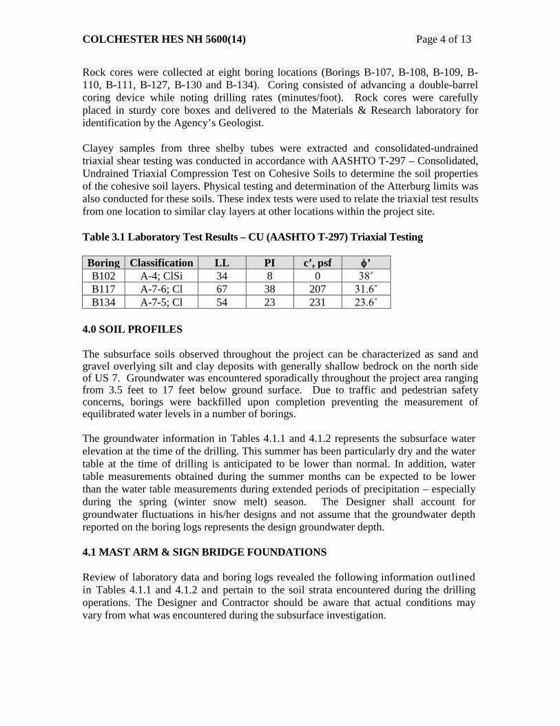
Rock cores were collected at eight boring locations (Borings B-107, B-108, B-109, B-110, B-111, B-127, B-130 and B-134). Coring consisted of advancing a double-barrel coring device while noting drilling rates (minutes/foot). Rock cores were carefully placed in sturdy core boxes and delivered to the Materials & Research laboratory for identification by the Agency’s Geologist. Clayey samples from three shelby tubes were extracted and consolidated-undrained triaxial shear testing was conducted in accordance with AASHTO T-297 – Consolidated, Undrained Triaxial Compression Test on Cohesive Soils to determine the soil properties of the cohesive soil layers. Physical testing and determination of the Atterburg limits was also conducted for these soils. These index tests were used to relate the triaxial test results from one location to similar clay layers at other locations within the project site. Table 3.1 Laboratory Test Results – CU (AASHTO T-297) Triaxial Testing Boring Classification LL PI c’, psf φ’ B102 A-4; ClSi 34 8 0 38˚ B117 A-7-6; Cl 67 38 207 31.6˚ B134 A-7-5; Cl 54 23 231 23.6˚
4.0 SOIL PROFILES The subsurface soils observed throughout the project can be characterized as sand and gravel overlying silt and clay deposits with generally shallow bedrock on the north side of US 7. Groundwater was encountered sporadically throughout the project area ranging from 3.5 feet to 17 feet below ground surface. Due to traffic and pedestrian safety concerns, borings were backfilled upon completion preventing the measurement of equilibrated water levels in a number of borings. The groundwater information in Tables 4.1.1 and 4.1.2 represents the subsurface water elevation at the time of the drilling. This summer has been particularly dry and the water table at the time of drilling is anticipated to be lower than normal. In addition, water table measurements obtained during the summer months can be expected to be lower than the water table measurements during extended periods of precipitation – especially during the spring (winter snow melt) season. The Designer shall account for groundwater fluctuations in his/her designs and not assume that the groundwater depth reported on the boring logs represents the design groundwater depth.
4.1 MAST ARM & SIGN BRIDGE FOUNDATIONS Review of laboratory data and boring logs revealed the following information outlined in Tables 4.1.1 and 4.1.2 and pertain to the soil strata encountered during the drilling operations. The Designer and Contractor should be aware that actual conditions may vary from what was encountered during the subsurface investigation.
COLCHESTER HES NH 5600(14) Page 5 of 13
Table 4.1.1 Mast Arm & Sign Bridge Soil Profile and Design Parameters (1 of 2)
9 – 10.2 dense to very dense SaSiGr 37 ----- 130 225
B115 0 – 4 medium to dense SiSaGr/SaClSi
7.1 320.06 30 ----- 115 90
CYL 4 – 8 medium to very stiff Cl to be determined 8 – 9.4 very dense SaGr 37 ----- 130 125
Note 1: Where the value for k is split (i.e., 90 / 60) it indicates the soil modulus for use above / below the water table. Note 2: CYL – cylindrical / shaft footing – diameter to be determined by designer SPR – square or rectangular spread footing with dimensions determined by designer Note 3: Gr = Gravel, Sa = Sand, Si = Silt, and Cl = Clay Note 4: GNE = Groundwater Not Encountered
COLCHESTER HES NH 5600(14) Page 6 of 13
Table 4.1.2 Mast Arm & Sign Bridge Soil Profile and Design Parameters (2 of 2)
Loc
atio
n
Bor
ing
Dep
th, f
t Soil Stratum Description
Gro
undw
ater
D
epth
, ft
Poss
ible
Bed
rock
E
leva
tion,
ft
Fric
tion
Ang
le,
degr
ees, φ’
Coh
esio
n, p
sf -
c’
Uni
t Wei
ght, γ
pcf
Soil
Mod
ulus
, k
(pci
)1
Req
uire
d Fo
unda
tion
Typ
e2
Ram
p D
Si
gn B
ridge
B116 0 – 4 loose to medium dense Sa3
3.5 311.80 30 ----- 110 20 CYL
or SPR 4 – 13.9 medium to very stiff Cl 23.6 231 120 200
B117
0 – 3 soft SaSiCl
GNE4 308.57
to be determined
CYL or SPR
3 – 6 very soft Cl to be determined 6 – 10 stiff Cl to be determined
10 – 12 stiff Cl 31.6 207 106 1000 12 – 14.2 stiff Cl to be determined
STA
15+
52
Sign
Brid
ge
B118 0 – 4.8 medium to dense GrSa / SaGr GNE 336.37 32 ----- 120 90 CYL or SPR B119 Hand steel probe indicated 4.1 ft to top of ledge or boulder
CYL 4 – 9.0 stiff to very stiff Cl to be determined
B123 Not drilled to large number of underground utilities - use Boring B122 design parameters CYL
Her
cule
s Dr.
Inte
rsec
tion
M
ast A
rms
B124
0 – 4 medium dense sands & gravels
4.0 321.6
31 ----- 115 90
CYL 4 – 6 medium SaSiCl to be determined 6 – 10 stiff Cl 23.6 231 120 1000
10 – 12.8 stiff to very stiff GrSaCl to be determined
B125 0 – 6.0 medium dense GrSa
GNE 326.1 31 ----- 115 90
CYL 6.0 – 7.2 medium SaSiCl to be determined
B126 0 – 4 dense to very dense Sa
GNE 323.75 32 ----- 120 225
CYL 4 - 10 medium to very stiff Cl 23.6 231 120 750 10 – 10.7 SaSi 32 ----- 120 225
B127 0 – 6 medium dense GrSa w/some Si
3.5 319.09 31 ----- 115 90
CYL 6 – 8 stiff SaSiCl to be determined 8 – 13.2 stiff to very stiff Cl 23.6 231 120 1000
Rat
he R
d / C
ham
plai
n D
rive
Inte
rsec
tion
M
ast A
rms
B128 0 – 7.2 medium to dense Sa & Gr GNE 312.53 32 ----- 120 150 CYL B129 0 – 3.5 medium to dense Sa & Gr GNE 315.69 32 ----- 120 150 CYL
B130 0 – 8 medim to dense Si & Sa
5.0 300.25 32 ----- 120 90 / 60
CYL 8 – 12.5 stiff to very stiff Cl 23.6 231 120 1000 12.5 – 15.5 very dense SaGrSi 37 ----- 130 125
B131 0 – 4 dense SaGr
5.0 307.22 35 ----- 125 225
CYL 4 – 8 medium dense SaSi / SiSa 30 ----- 110 90 / 60 8 – 10.9 medium SaSiCl to be determined
Note 1: Where the value for k is split (i.e., 90 / 60) it indicates the soil modulus for use above / below the water table. Note 2: CYL – cylindrical / shaft footing – diameter to be determined by designer SPR – square or rectangular spread footing with dimensions determined by designer Note 3: Gr = Gravel, Sa = Sand, Si = Silt, and Cl = Clay Note 4: GNE = Groundwater Not Encountered
COLCHESTER HES NH 5600(14) Page 7 of 13
4.2 RETAINING WALLS There are three retaining walls proposed for this project. Two of the retaining walls are proposed to retain embankment material which will accommodate the construction of sidewalks and safety improvements associated with the double diamond intersection. These retaining walls are intended to support each pair of interstate abutments, and are expected to be between 10 and 15 feet in height. The existing piers will remain but will be located between the proposed retaining walls and the proposed sidewalk/bike path and the roadway. Table 4.2 depicts a summary of the information obtained from the subsurface investigation. However, hand steel soundings alone are insufficient to allow for the proper design of the retaining walls at the Exit 16 interchange. It is recommended that a minimum of 3 to 4 wall borings be obtained for each abutment retaining wall. These walls are anticipated to be constructed using a top down construction method. Three types of wall systems that should be considered include a soldier pile and lagging wall, soil nail wall, and an anchored wall system. Two of the four wall borings should be obtained a distance of 0.7 to 1.0 times the wall height behind the face of the wall. Limitations include shallow bedrock and limited vertical clearance for construction equipment. The as-built plans depict the existing northern abutments to be spread footings placed directly on bedrock. Therefore, the wall in front of the northern abutments is likely to encounter bedrock, thus necessitating the development of a thorough bedrock profile to determine the amount of soil and/or rock removal and to ascertain the available resistance for ground anchors and soil nails. The follow-up investigation should determine whether or not it is feasible to have an engineered rock cut in the vicinity of the northern abutments which may depend equally on the line and grade of the wall and the subsurface information. The retaining wall located in front of the southern abutments is not expected to encounter bedrock however a review of the original plans indicates that the southern abutments are supported by steel H-piles which could potentially conflict with drilled-in structural inclusions such as ground anchors or soil nails. The third retaining wall is located along Lower Mountain View Drive from Station 502+37 to Station 503+64, LT. No borings have been drilled for this wall; Boring B-134 of Table 4.2, was drilled in the immediate vicinity of a wall originally proposed to be constructed in the southwest corner of Lower Mountain View Drive and US 7. B-134 could provide some geotechnical information relative to the anticipated soil conditions for the third structure but should not be used for design purposes until additional borings can confirm the applicability of B-134 to the structure location. Two additional wall borings are anticipated to a depth of 25 ft or bedrock – whichever comes first. This wall is anticipated to be a maximum of 5 feet high and does not represent a large engineering concern, however, the presence of soft marine clays requires a couple of borings to investigate the competency of the foundation soil, to determine the necessity of a foundation undercut and to ensure accurate project quantities. It is recommended that an accurate survey be conducted for the beginning and end of wall sections along with wall sections every 10 feet and sent to the Soils & Foundations Unit so that appropriate subsurface investigation can be planned which will facilitate design recommendations for the preferred wall type(s) for this project.
COLCHESTER HES NH 5600(14) Page 8 of 13
Table 4.2 Retaining Wall Subsurface Information
Loc
atio
n
Bor
ing
Dep
th, f
t
Soil Stratum Description
Gro
undw
ater
D
epth
, ft
Poss
ible
Bed
rock
E
leva
tion,
ft
Fric
tion
Ang
le, φ
’ ˚
Coh
esio
n, p
sf -
c’
Uni
t Wei
ght, γ p
cf
Ant
icip
ated
Wal
l T
ype2
North Abutment B132 Hand steel probe indicated 5.5 ft to top of ledge or boulder TBD
South Abutment B133 Hand steel probe indicated 11.5 ft to top of ledge or boulder TBD
Lower Mtn View Drive B134
0 – 2 medium to stiff SaSiCl None 339.90
unknown PMB
2 – 8.5 stiff to very stiff Cl 23.6 231 120 Note 2: TBD – to be determined PMB – precast modular block wall
4.3 EXISTING PAVEMENT CROSS SECTION Solid stem augers were drilled at 5 different locations along the project alignment. The generalized pavement profile beneath the ground surface consists of 0 to 9.5 inches of asphalt pavement followed by 24 inches of a subbase (SaGr) material. The augers extended to a depth of 5 ft and were terminated in a silty-sand (SiSa) material that contained various amounts of gravel. The SaGr and SiSa layers averaged 13.9% and 24.0% fines content (material finer than the #200 sieve), respectively.
5.0 BEDROCK CONDITIONS Confirmed bedrock encountered across the project varies in depth from exposures at the surface to depths of 15.5-feet below ground surface. Borings B-102, B-104 and B-106 at the southern end of the project (near the intersection of US2/US7 and S. Park Drive) encountered auger refusal at depths of 25.6, 24.7 and 21.2 respectively. The dip of the top of bedrock surface is from northwest to southeast with numerous surface exposures on the northwest side of US-2/US7 and along the northbound on-ramp and southbound off-ramp of I-89 Interchange 16. Bedrock consists of light gray dolomite (dolostone) with closely spaced jointing. The 2011 Vermont State Bedrock Geologic map reports that the area of this project is underlain by the Winooski Dolostone Formation described as “Well-bedded dolostone weathering beige, cream, and buff, with green, red, or gray phyllite, siliceous partings, and thin beds of blue-quartz-pebble conglomerate and quartzite”. Karst features in the form of solution cavity horizons (along bedding) were noted in some of the rock core samples. These karst features are relatively small in scale (little or no drilling breaks were reported). Figure 1 shows an excavated face adjacent to the Price Chopper supermarket parking lot located about 500-feet northwest of the intersection of US2/US7 and Mountain View Drive. A solution cavity can be seen about 1/3 of the way
COLCHESTER HES NH 5600(14) Page 9 of 13
below the top of the exposure. Observations made of the exposed rock in roadway cuts and two large excavated faces at nearby businesses show that the rock breaks along the closely spaced jointing resulting in exposures that have a broken-up appearance. This condition leads to raveling failures on slope faces and the development of overhangs (Figure 2). Core logs developed by the AOT geologist are attached. These logs include a photograph of the cores taken, lithologic descriptions, pertinent information such as depth of sample, percent recovery, RQD and RMR (Rock Mass Rating).
Figure 1: Photograph of rock exposure at Price Chopper parking lot northwest of the intersection of US2/US7 and Mountain View Drive. Solution cavity can be seen as horizontal zone about 1/3 of the way from the top of the exposure.
Figure 2: Photograph of westward facing rock cut along I-89 Interchange 16 northbound on-ramp. Note the presence of overhangs resulting from the deterioration along closely spaced jointing in the rock.
COLCHESTER HES NH 5600(14) Page 10 of 13
6.0 RECOMMENDATIONS 6.1. LEDGE REMOVAL As indicated in the previous section of this report, bedrock consists of dolomite that contains numerous closely spaced joints. Dilation along these joint surfaces has led to slopes that are susceptible to raveling failures and the development of overhanging masses of rock. The presence of closely spaced jointing and the small amount of burden (distance between the existing slope face and the newly planned face), may make traditional presplit blasting difficult as the joint surfaces will provide avenues for the blast energy to propagate through the openings resulting in poor controlled fracture of the rock. We recommend that ledge removal be conducted as follows: Mechanical Excavation Mechanical methods would include the use of a medium size hydraulic excavator. Closely spaced jointing within the slope may allow for this type of removal as the small blocks bound by the joint sets in the rock may make it easier to pluck them from the slope. Care should be taken to transition into adjacent rock exposures and structures (retaining wall, bridge footings and pile foundations). Trim (Cushion) Blasting Along Ramps A and B and from Station 13+50 to 17+00 trim blasting should be conducted. Trim blasting is similar to presplit blasting except one of the primary differences is that the final row of blast holes is fired after all production holes are fired. The charge is typically reduced in the final row of holes to protect the final cut face from blowback damage. Line Drilling and Blasting Blasting in close proximity to the bridge abutment footings should be conducted utilizing line drilling techniques. Line drilling consists of drilling a line of unloaded (not loaded with explosives) closely spaced holes parallel to one another, along the final neat line of the excavation. This technique produces a plane of weakness which forms a breakage plane when the production shots are fired. This acts as a barrier to stress waves from the production blast holes. Line drilling can be very effective in areas where close-by infrastructure such as bridge foundations need to be protected or where the character of the rock would promote venting of gas back into the final excavation wall. Line drilling holes generally have a diameter of 2 to 3-inches. Hole diameters greater than 3-inches tend to be ineffective and therefore are seldom used. The row of production blasting holes closest to the line of empty holes should be fired last and have a closer spacing (50-75%) and around 50% less explosive charge than the other production shots. The charge should be spread down the hole using detonating cord as the initiator. Line drilling is more costly than presplit blasting methods due to the large number of drill holes that would need to be performed.
COLCHESTER HES NH 5600(14) Page 11 of 13
For the reasons discussed above, traditional presplit blasting should not be permitted. Any blasting performed on the project will require a pre-blast survey be performed and all blasts will be required to utilize protective matting over the blast area to protect from possible fly-rock. We have comprehensive blasting specifications for some recent projects covering these requirements. Upon your request we can develop similar specifications for this project. 6.2 Mast Arm and Sign Bridge Foundations Due to site constraints the foundations for the mast arms are required to be cylindrical footings while the sign bridges are required to be either a spread footing or a cylindrical footing as noted in Tables 4.1.1 and 4.1.2. The cylindrical footings shall be installed as described by the designer and may be formed from driven casing, formed casing, or drilled. The type of construction methods utilized will affect the structure’s ability to resist torque. The foundations shall be designed in accordance with VTrans’ MREI 10-01. Earth pressure coefficients can be calculated using the soil’s internal friction angle. Friction factors can be determined from published values in the NAVFAC design manual; DM 7.02. 6.3 Retaining Walls It is recommended that a survey be conducted for each retaining wall. Cross sections should be provided that document the existing project conditions (wall sections) along the wall at 10 feet increments including the beginning and end of wall sections. These cross sections should be delivered to the Soils & Foundations Unit so that an appropriate subsurface investigation can be planned to facilitate design recommendations for the preferred wall type(s) for this project. A minimum of 3 to 4 wall borings are recommended to be drilled for each abutment retaining wall. These walls are anticipated to be constructed using a top down construction method. Top down construction methods include the following three wall systems or types; a “modified”) soldier pile and lagging wall (possibly utilizing drilled in-place H-piles), soil nail wall, and an anchored wall system. Two of the four wall borings should be obtained a distance of 0.7 to 1.0 times the wall height behind the face of the wall. Known project limitations include shallow bedrock and limited vertical clearance for construction equipment. Two additional wall borings are recommended to be drilled for the retaining wall along Lower Mountain View Drive from Station 502+37 to Station 503+64, LT. The borings should be drilled to a depth of 25 ft or bedrock, whichever comes first. 6.4 Additional Laboratory Testing It is recommended that triaxial tests be conducted on material classified as A6; SaSiCl to identify pertinent soil strength parameters.
COLCHESTER HES NH 5600(14) Page 12 of 13
6.5 Construction Considerations
6.5.1 Construction Dewatering: The construction of spread footings will require a minimum embedment of 5 feet and may encounter groundwater. Therefore, temporary construction dewatering may be required to construct spread and/or cylindrical foundations. Temporary dewatering may also be necessary to limit disturbance to and maintain the integrity of the bearing surface. Temporary dewatering can likely be accomplished by open pumping from shallow sumps, temporary ditches, and trenches within and around the excavation limits. Sumps should be provided with filters suitable to prevent pumping of fine-grained soil particles. The water trapped by the temporary dewatering controls should be discharged to settling basins or an approved filter “sock” so that the fine particles suspended in the discharge have adequate time to “settle out” prior to discharge. All effluent, or discharge, should comply with all applicable permits and regulations. Sumps and trenches should lie outside a 1V:1H line extending downward and outward from the edge of the footing. Installation and operation of the Contractor’s dewatering system should be integrated with other earthwork operations and sequence of cutting, filling, foundation construction, and backfilling. 6.5.2 Subgrade Preparation: Areas exhibiting excessive weaving, soft, or unstable soils should be excavated a minimum of 1 foot and replaced with compacted Granular Backfill for Structures (VTrans’ pay item 704.08). 6.5.3 Placement and Compaction of Backfill Material: Select fill material, such as Granular Backfill for Structures, should be placed systematically in horizontal layers not more than 12 inches in thickness, prior to compaction. Cobbles larger than 8 inches should be removed from the fill prior to placement. Where hand-guided compaction equipment, such as a small vibratory plate compactor, is used the loose lift thickness shall not exceed 6 inches. Cobbles larger than 4 inches should be removed from the fill prior to placement. Granular Backfill for Structures, or other select materials placed shall be compacted to a dry density of 95% of the maximum dry density determined in accordance with AASHTO T-99 – Moisture-Density Relations of Soils Using a 2.5 kg (5.5 lb) Rammer and a 305-mm (12 in.) Drop.
6.6 Design Guidelines The Materials and Research Section of VTrans has developed Materials and Research Engineering Instructions (MREI) 10-01, which “standardizes VTrans’ foundation designs for overhead structures such as signal or sign bridges, mast arms, and strain poles during plan (preliminary and final) development or construction.” This document should be referenced in the project plans and specifications for the contractor’s use. The document is available on the Agency’s website at the following address:
COLCHESTER HES NH 5600(14) Page 13 of 13
http://www.aot.state.vt.us/progdev/Sections/M&R%20Info/DocumentsM&RPages/M&R SoilEI%20-%20Overhead%20Structures%20030910.pdf In addition, it is highly recommended that this geotechnical report be included in the project’s bid documents and referenced in the general notes on the project plan documents. 7.0 CONCLUSIONS If any further analysis is needed or you would like to discuss this report, please contact us at (802) 828-2561. Typed boring logs are attached and are available in the CADD design files: M:\Projects\12d046\Materials&Research.
MATERIALS & RESEARCH SECTIONSUBSURFACE INFORMATION
BORING LOG
COLCHESTERHES NH 5600(14)
Dep
th(f
t)
5
10
15
20
25
US2 & US7
Boring Crew: PORTER, GARROW, SALISBURY
Date Started: 7/20/12 Date Finished: 7/20/12
VTSPG NAD83: N 731095.68 ft E 1462467.81 ft
Ground Elevation: 326.52 ft
Boring No.: B-101
Page No.: 1 of 1
Pin No.: 12D046
Checked By: TDE
Blo
ws/
6"(N
Val
ue)
Date Depth(ft)
Notes
Notes:
Hammer Fall:Hammer Wt:I.D.:Type:
1. Stratification lines represent approximate boundary between material types. Transition may be gradual.2. N Values have not been corrected for hammer energy. CE is the hammer energy correction factor.3. Water level readings have been made at times and under conditions stated. Fluctuations of groundwater may occur due to other factors than those present at the time
A-4, ClSi, brn, MTW, Rec. = 2.0 ft, Material from Triaxial "B" Test Sample.
Visual Description:, ClSi, brn, MTW, Rec. = 2.0 ft, Similar material as 14-16 ft.
A-4, ClSi, brn, MTW, Rec. = 2.0 ft
A-7-6, Cl, gry, MTW, Rec. = 2.0 ft
Visual Description:, Cl, gry, MTW, Rec. = 1.7 ft, Similar material as 19-21 ft.
Hole stopped @ 25.6 ftCNPF-TLOB
30
34
34
52
4
8
7
30
STATE OF VERMONTAGENCY OF TRANSPORTATION
MATERIALS & RESEARCH SECTIONSUBSURFACE INFORMATION
BORING LOG
COLCHESTERHES NH 5600(14)
Dep
th(f
t)
5
10
15
20
25
US2 & US7
Boring Crew: PORTER, GARROW, SALISBURY
Date Started: 7/20/12 Date Finished: 7/20/12
VTSPG NAD83: N 731069.44 ft E 1462559.12 ft
Ground Elevation: 324.59 ft
Boring No.: B-102
Page No.: 1 of 1
Pin No.: 12D046
Checked By: TDE
Blo
ws/
6"(N
Val
ue)
Date Depth(ft)
Notes
Notes:
Hammer Fall:Hammer Wt:I.D.:Type:
1. Stratification lines represent approximate boundary between material types. Transition may be gradual.2. N Values have not been corrected for hammer energy. CE is the hammer energy correction factor.3. Water level readings have been made at times and under conditions stated. Fluctuations of groundwater may occur due to other factors than those present at the time
Remarks:1. At Station 5+14: Electrical caution tape was within the 2.0'- 3.7' sample.2. Moved Hole to 5+19 and advanced casing to 3.7 feet, but could not penatrate further.
STATE OF VERMONTAGENCY OF TRANSPORTATION
MATERIALS & RESEARCH SECTIONSUBSURFACE INFORMATION
BORING LOG
COLCHESTERHES NH 5600(14)
Dep
th(f
t)
5
10
15
20
25
US2 & US7
Boring Crew: PORTER, GARROW, SALISBURY
Date Started: 7/19/12 Date Finished: 7/19/12
VTSPG NAD83: N 731191.52 ft E 1462490.85 ft
Ground Elevation: 325.0 ft
Boring No.: B-103
Page No.: 1 of 1
Pin No.: 12D046
Checked By: TDE
Blo
ws/
6"(N
Val
ue)
Date Depth(ft)
Notes
Notes:
Hammer Fall:Hammer Wt:I.D.:Type:
1. Stratification lines represent approximate boundary between material types. Transition may be gradual.2. N Values have not been corrected for hammer energy. CE is the hammer energy correction factor.3. Water level readings have been made at times and under conditions stated. Fluctuations of groundwater may occur due to other factors than those present at the time
Visual Description:, Si, brn, MTW, Rec. = 2.0 ft, Similar material as 14-16 ft.
A-4, Si, gry, MTW, Rec. = 2.0 ft
A-7-6, Cl, gry, MTW, Sample from middle of tube.
Visual Description:, Si with stones, gry, MTW, Rec. = 0.2 ft, Similar material as14-16 ft.
Hole stopped @ 24.7 ftCNPF-TLOB
33
30
56
7
6
33
STATE OF VERMONTAGENCY OF TRANSPORTATION
MATERIALS & RESEARCH SECTIONSUBSURFACE INFORMATION
BORING LOG
COLCHESTERHES NH 5600(14)
Dep
th(f
t)
5
10
15
20
25
US2 & US7
Boring Crew: PORTER, GARROW, SALISBURY
Date Started: 7/20/12 Date Finished: 7/23/12
VTSPG NAD83: N 731168.78 ft E 1462581.18 ft
Ground Elevation: 324.79 ft
Boring No.: B-104
Page No.: 1 of 1
Pin No.: 12D046
Checked By: TDE
Blo
ws/
6"(N
Val
ue)
Date Depth(ft)
Notes
Notes:
Hammer Fall:Hammer Wt:I.D.:Type:
1. Stratification lines represent approximate boundary between material types. Transition may be gradual.2. N Values have not been corrected for hammer energy. CE is the hammer energy correction factor.3. Water level readings have been made at times and under conditions stated. Fluctuations of groundwater may occur due to other factors than those present at the time
A-2-4, SiGrSa, brn, MTW, Rec. = 1.5 ft, Broken Rock was within sample.
A-1-b, SaGr, brn, MTW, Rec. = 0.8 ft
A-1-b, SaGr, brn, MTW, Rec. = 0.6 ft
Visual Description:, SaGr, brn, MTW, Rec. = 0.2 ft
A-1-b, SaGr, brn, MTW, Rec. = 1.2 ft
Visual Description:, Broken Rock, gry, MTW, Rec. = 1.0 ft
Hole stopped @ 11.0 ftCNPF-TLOB
STATE OF VERMONTAGENCY OF TRANSPORTATION
MATERIALS & RESEARCH SECTIONSUBSURFACE INFORMATION
BORING LOG
COLCHESTERHES NH 5600(14)
Dep
th(f
t)
5
10
15
20
25
US2 & US7
Boring Crew: PORTER, GARROW, SALISBURY
Date Started: 7/19/12 Date Finished: 7/19/12
VTSPG NAD83: N 731274.17 ft E 1462509.62 ft
Ground Elevation: 327.76 ft
Boring No.: B-105
Page No.: 1 of 1
Pin No.: 12D046
Checked By: TDE
Blo
ws/
6"(N
Val
ue)
Date Depth(ft)
Notes
Notes:
Hammer Fall:Hammer Wt:I.D.:Type:
1. Stratification lines represent approximate boundary between material types. Transition may be gradual.2. N Values have not been corrected for hammer energy. CE is the hammer energy correction factor.3. Water level readings have been made at times and under conditions stated. Fluctuations of groundwater may occur due to other factors than those present at the time
measurements were made.
Collapsed at 6.2 ft.
None taken.
CE = 1.34
Moi
stur
eC
onte
nt %
Rig: CME 45C TRACKHammer/Rod Type: Auto/AWJ
SS1.5 in140 lb.30 in.
H.S.A.3.5 inN.A.N.A.
Casing Sampler
Offset: -50.40
Gra
vel %
San
d %
Fin
es %
Groundwater Observations
CLASSIFICATION OF MATERIALS(Description)
Str
ata
(1)
Station: 5+98
BO
RIN
G L
OG
2 C
OLC
HE
ST
ER
HE
S N
H 5
600(
14).
GP
J V
ER
MO
NT
AO
T.G
DT
9/1
1/1
2
2-2-3-22(5)
5-3-4-4(7)
3-3-2-2(5)
3-5-4-7(9)
3-4-5-4(9)
4-4-3-3(7)
WH-1-1-2
(2)
WH-1-1-2
(2)
16.6
12.0
21.8
26.0
30.1
32.1
34.5
34.8
15.4
39.8
11.7
0.7
10.5
39.5
30.4
38.9
3.2
3.8
24.0
45.1
29.8
49.4
96.1
96.2
65.5
A-4, SaSi, brn, MTW, Rec. = 1.0 ft
A-2-4, SiSaGr, gry, MTW, Rec. = 0.7 ft, Broken Rock was within sample.
A-4, SaSi, brn, MTW, Rec. = 1.8 ft
A-4, Si, brn, MTW, Rec. = 2.0 ft
Visual Description:, ClSi, gry, MTW, Rec. = 1.8 ft, Similar material as 10-12 ft.
A-4, ClSi, gry, MTW, Rec. = 1.7 ft
Visual Description:, ClSi, gry, MTW, Rec. = 1.8 ft, Similar material as 10-12 ft.
A-7-6, Cl, gry, MTW, Rec. = 2.0 ft
Hole stopped @ 21.2 ftCNPF-TLOB
29
34
47
4
7
27
STATE OF VERMONTAGENCY OF TRANSPORTATION
MATERIALS & RESEARCH SECTIONSUBSURFACE INFORMATION
BORING LOG
COLCHESTERHES NH 5600(14)
Dep
th(f
t)
5
10
15
20
25
US2 & US7
Boring Crew: PORTER, GARROW, SALISBURY
Date Started: 7/23/12 Date Finished: 7/23/12
VTSPG NAD83: N 731243.87 ft E 1462597.56 ft
Ground Elevation: 326.03 ft
Boring No.: B-106
Page No.: 1 of 1
Pin No.: 12D046
Checked By: TDE
Blo
ws/
6"(N
Val
ue)
Date Depth(ft)
Notes
Notes:
Hammer Fall:Hammer Wt:I.D.:Type:
1. Stratification lines represent approximate boundary between material types. Transition may be gradual.2. N Values have not been corrected for hammer energy. CE is the hammer energy correction factor.3. Water level readings have been made at times and under conditions stated. Fluctuations of groundwater may occur due to other factors than those present at the time
measurements were made.
07/23/12 17.0 Same Day.
CE = 1.34
Moi
stur
eC
onte
nt %
Rig: CME 45C TRACKHammer/Rod Type: Auto/AWJ
SS1.5 in140 lb.30 in.
H.S.A.3.25 inN.A.N.A.
Casing Sampler
Offset: 43.00
Gra
vel %
San
d %
Fin
es %
Groundwater Observations
CLASSIFICATION OF MATERIALS(Description)
Str
ata
(1)
Station: 5+96
BO
RIN
G L
OG
2 C
OLC
HE
ST
ER
HE
S N
H 5
600(
14).
GP
J V
ER
MO
NT
AO
T.G
DT
9/1
1/1
2
LL %
PI %
2-3-3-9(6)
9-13-10-10
(23)
3-1-WH-1
(1)
4.4
3.8
6.1
54.8
55.0
31.7
32.0
13.5
13.0
A-1-a, SaGr, brn, MTW, Rec. = 0.6 ft
A-1-a, SaGr, brn, Moist, Rec. = 0.6 ft
Visual Description:, SaGr with Broken Rock, gry, MTW, Rec. = 0.2 ft,Possible Voids were in this area. Insufficient sample for testing.
6.0 ft - 9.2 ft, Light gray, Dolomite, Moderately hard, Unweathered, Poorrock, BXMDC, Closely space jointing. RMR = 38
9.2 ft - 14.2 ft, Light gray, Dolomite, Moderately hard, Unweathered, Fairrock, BXMDC, Closely space jointing. RMR = 48
Hole stopped @ 14.2 ft
1(10)
2(10)
100(22)
94(54)
9
5
6
4
4
3
4
5
STATE OF VERMONTAGENCY OF TRANSPORTATION
MATERIALS & RESEARCH SECTIONSUBSURFACE INFORMATION
BORING LOG
COLCHESTERHES NH 5600(14)
Dep
th(f
t)
5
10
15
20
25
US2 & US7
Boring Crew: PORTER, GARROW, SALISBURY
Date Started: 7/11/12 Date Finished: 7/12/12
VTSPG NAD83: N 731553.69 ft E 1462584.21 ft
Ground Elevation: 325.07 ft
Boring No.: B-107
Page No.: 1 of 1
Pin No.: 12D046
Checked By: TDE
Blo
ws/
6"(N
Val
ue)
Date Depth(ft)
Notes
Notes:
Hammer Fall:Hammer Wt:I.D.:Type:
1. Stratification lines represent approximate boundary between material types. Transition may be gradual.2. N Values have not been corrected for hammer energy. CE is the hammer energy correction factor.3. Water level readings have been made at times and under conditions stated. Fluctuations of groundwater may occur due to other factors than those present at the time
Visual Description:, SaGr with 1.5" stones, brn, MTW, Rec. = 0.2 ft,Insufficient sample for testing.
Visual Description:, SaGr with 1.5" stones, brn, MTW, Rec. = 0.2 ft,Insufficient sample for testing.
A-1-a, SaGr, brn, MTW, Rec. = 1.0 ft, Broken Rock was within sample.
10.0 ft - 15.0 ft, Light gray, Dolomite, Moderately hard, Unweathered,Fair rock, BXMDC, Close to moderately closely spaced jointing. RMR =53
Hole stopped @ 15.0 ft
1(10)
100(52)
6
5
6
6
5
STATE OF VERMONTAGENCY OF TRANSPORTATION
MATERIALS & RESEARCH SECTIONSUBSURFACE INFORMATION
BORING LOG
COLCHESTERHES NH 5600(14)
Dep
th(f
t)
5
10
15
20
25
US2 & US7
Boring Crew: PORTER, GARROW, SALISBURY
Date Started: 7/18/12 Date Finished: 7/18/12
VTSPG NAD83: N 731605.46 ft E 1462627.28 ft
Ground Elevation: 327.25 ft
Boring No.: B-108
Page No.: 1 of 1
Pin No.: 12D046
Checked By: TDE
Blo
ws/
6"(N
Val
ue)
Date Depth(ft)
Notes
Notes:
Hammer Fall:Hammer Wt:I.D.:Type:
1. Stratification lines represent approximate boundary between material types. Transition may be gradual.2. N Values have not been corrected for hammer energy. CE is the hammer energy correction factor.3. Water level readings have been made at times and under conditions stated. Fluctuations of groundwater may occur due to other factors than those present at the time
measurements were made.
None Taken.
Same day drilling.
CE = 1.34
Moi
stur
eC
onte
nt %
Rig: CME 45C TRACKHammer/Rod Type: Auto/AWJ
SS1.5 in140 lb.30 in.
WB3 inN.A.N.A.
Casing Sampler
Offset: -38.00
Gra
vel %
San
d %
Fin
es %
Groundwater Observations
CLASSIFICATION OF MATERIALS(Description) R
un(D
ip d
eg.)
Cor
e R
ec. %
(RQ
D %
)
Dri
ll R
ate
min
utes
/ft
Str
ata
(1)
Station: 9+50
BO
RIN
G L
OG
2 C
OLC
HE
ST
ER
HE
S N
H 5
600(
14).
GP
J V
ER
MO
NT
AO
T.G
DT
9/1
1/1
2
Top of Bedrock @ 10.0 ft
22-8-17-28
(25)
12-27-21-19(48)
3-5-6-12(11)
1.2
5.8
1.4
59.9
41.1
78.0
26.1
46.3
15.2
14.0
12.6
6.8
Asphalt Pavement, 0.0 ft - 0.7 ft
A-1-a, SaGr with lots of Asphalt Pavement within sample, brn, Moist,Sample from auger flights.
A-1-b, GrSa, brn, Moist, Rec. = 1.8 ft
A-1-a, Gr, gry, Moist, Rec. = 1.3 ft, Broken Rock was within sample.
Visual Description:, Broken Rock, gry, Wet, Rec. = 0.5 ft
9.9 ft - 10.7 ft, Light gray, Dolomite, Moderately hard, Unweathered,Poor rock, BXMDC, Mechanical breakage. RMR = 3810.7 ft - 11.7 ft, Light gray, Dolomite, Moderately hard, Unweathered,Poor rock, BXMDC, Mechanical breakage. RMR = 3811.7 ft - 16.7 ft, Light gray, Dolomite, Moderately hard, Unweathered,Fair rock, BXMDC, Mechanical breakage. RMR = 48
Hole stopped @ 16.7 ft
1(10)
2(10)
3(10)
4(10)
70
100
100
96(56)
7
7
7
8
7
8
4
4
5
STATE OF VERMONTAGENCY OF TRANSPORTATION
MATERIALS & RESEARCH SECTIONSUBSURFACE INFORMATION
BORING LOG
COLCHESTERHES NH 5600(14)
Dep
th(f
t)
5
10
15
20
25
US2 & US7
Boring Crew: PORTER, GARROW, SALISBURY
Date Started: 7/11/12 Date Finished: 7/11/12
VTSPG NAD83: N 731658.62 ft E 1462644.29 ft
Ground Elevation: 327.44 ft
Boring No.: B-109
Page No.: 1 of 1
Pin No.: 12D046
Checked By: TDE
Blo
ws/
6"(N
Val
ue)
Date Depth(ft)
Notes
Notes:
Hammer Fall:Hammer Wt:I.D.:Type:
1. Stratification lines represent approximate boundary between material types. Transition may be gradual.2. N Values have not been corrected for hammer energy. CE is the hammer energy correction factor.3. Water level readings have been made at times and under conditions stated. Fluctuations of groundwater may occur due to other factors than those present at the time
measurements were made.
No water to depth.
CE = 1.34
Moi
stur
eC
onte
nt %
Rig: CME 45C TRACKHammer/Rod Type: Auto/AWJ
SS1.5 in140 lb.30 in.
H.S.A.3.25 inN.A.N.A.
Casing Sampler
Offset: -37.00
Gra
vel %
San
d %
Fin
es %
Groundwater Observations
CLASSIFICATION OF MATERIALS(Description) R
un(D
ip d
eg.)
Cor
e R
ec. %
(RQ
D %
)
Dri
ll R
ate
min
utes
/ft
Str
ata
(1)
Station: 10+06
BO
RIN
G L
OG
2 C
OLC
HE
ST
ER
HE
S N
H 5
600(
14).
GP
J V
ER
MO
NT
AO
T.G
DT
9/1
1/1
2
Top of Bedrock @ 8.2 ft
1-3-9-29(12)
25-33-26-21(59)
5.8
0.7
58.4
73.3
31.1
19.2
10.5
7.5
A-1-a, SaGr, brn, Moist, Rec. = 1.0 ft
A-1-a, Gr, gry, Moist, Rec. = 1.6 ft
4.0 ft - 5.0 ft, Broken Rock. Not Competent.. BXDC, Possible Bedrock.
MATERIALS & RESEARCH SECTIONSUBSURFACE INFORMATION
BORING LOG
COLCHESTERHES NH 5600(14)
Dep
th(f
t)
5
10
15
20
25
US2 & US7
Boring Crew: PORTER, GARROW, SALISBURY
Date Started: 7/11/12 Date Finished: 7/16/12
VTSPG NAD83: N 731683.62 ft E 1462492.52 ft
Ground Elevation: 327.23 ft
Boring No.: B-110
Page No.: 1 of 1
Pin No.: 12D046
Checked By: TDE
Blo
ws/
6"(N
Val
ue)
Date Depth(ft)
Notes
Notes:
Hammer Fall:Hammer Wt:I.D.:Type:
1. Stratification lines represent approximate boundary between material types. Transition may be gradual.2. N Values have not been corrected for hammer energy. CE is the hammer energy correction factor.3. Water level readings have been made at times and under conditions stated. Fluctuations of groundwater may occur due to other factors than those present at the time
10.2 ft - 12.2 ft, Light gray, Dolomite, Moderately hard, Unweathered,Poor rock, BX, Closely spaced jointing. RMR = 38
12.2 ft - 17.2 ft, Light gray, Dolomite, Moderately hard, Unweathered,Fair rock, BX, Closely spaced jointing. RMR = 48
Hole stopped @ 17.2 ft
1(10)
2(10)
3(10)
4(10)
100(0)100(0)
100(0)
98(58)
6
3
5
5
7
4
5
7
7
7
STATE OF VERMONTAGENCY OF TRANSPORTATION
MATERIALS & RESEARCH SECTIONSUBSURFACE INFORMATION
BORING LOG
COLCHESTERHES NH 5600(14)
Dep
th(f
t)
5
10
15
20
25
US2 & US7
Boring Crew: PORTER, GARROW, SALISBURY
Date Started: 7/11/12 Date Finished: 7/18/12
VTSPG NAD83: N 731732.13 ft E 1462518.45 ft
Ground Elevation: 329.14 ft
Boring No.: B-111
Page No.: 1 of 1
Pin No.: 12D046
Checked By: TDE
Blo
ws/
6"(N
Val
ue)
Date Depth(ft)
Notes
Notes:
Hammer Fall:Hammer Wt:I.D.:Type:
1. Stratification lines represent approximate boundary between material types. Transition may be gradual.2. N Values have not been corrected for hammer energy. CE is the hammer energy correction factor.3. Water level readings have been made at times and under conditions stated. Fluctuations of groundwater may occur due to other factors than those present at the time
measurements were made.
07/19/12 5.9 AM
CE = 1.34
Moi
stur
eC
onte
nt %
Rig: CME 45C TRACKHammer/Rod Type: Auto/AWJ
SS1.5 in140 lb.30 in.
H.S.A.3.5 inN.A.N.A.
Casing Sampler
Offset: -24.80
Gra
vel %
San
d %
Fin
es %
Groundwater Observations
CLASSIFICATION OF MATERIALS(Description) R
un(D
ip d
eg.)
Cor
e R
ec. %
(RQ
D %
)
Dri
ll R
ate
min
utes
/ft
Str
ata
(1)
Station: A 0+66
BO
RIN
G L
OG
2 C
OLC
HE
ST
ER
HE
S N
H 5
600(
14).
GP
J V
ER
MO
NT
AO
T.G
DT
9/1
1/1
2
Top of Bedrock @ 7.2 ft
2-3-1-2(4)
1-2-1-1(3)
3-1-2-4(3)
5-3-3-4(6)
4-2-4-4(6)
2-3-5-7(8)
7.8
1.9
5.5
10.1
24.6
29.2
24.3
17.3
17.5
12.7
11.1
0.3
54.1
73.5
66.2
56.8
28.3
4.3
21.6
9.2
16.3
30.5
60.6
95.4
A-2-4, SiGrSa, brn, Moist, Rec. = 0.8 ft
A-1-b, Sa, brn, Moist, Rec. = 1.3 ft
A-2-4, Sa, brn, Moist, Rec. = 0.9 ft
A-2-4, SiSa, brn, MTW, Rec. = 0.9 ft
A-6, SaCl, brn, MTW, Rec. = 0.6 ft
A-7-6, Cl, gry, MTW, Rec. = 1.1 ft
Hole stopped @ 12.5 ftCNPF-TLOB
39
50
21
24
STATE OF VERMONTAGENCY OF TRANSPORTATION
MATERIALS & RESEARCH SECTIONSUBSURFACE INFORMATION
BORING LOG
COLCHESTERHES NH 5600(14)
Dep
th(f
t)
5
10
15
20
25
US2 & US7
Boring Crew: PORTER, GARROW, SALISBURY
Date Started: 7/11/12 Date Finished: 7/11/12
VTSPG NAD83: N 731825.72 ft E 1462793.35 ft
Ground Elevation: 330.96 ft
Boring No.: B-112
Page No.: 1 of 1
Pin No.: 12D046
Checked By: TDE
Blo
ws/
6"(N
Val
ue)
Date Depth(ft)
Notes
Notes:
Hammer Fall:Hammer Wt:I.D.:Type:
1. Stratification lines represent approximate boundary between material types. Transition may be gradual.2. N Values have not been corrected for hammer energy. CE is the hammer energy correction factor.3. Water level readings have been made at times and under conditions stated. Fluctuations of groundwater may occur due to other factors than those present at the time
measurements were made.
No water to depth.
CE = 1.34
Moi
stur
eC
onte
nt %
Rig: CME 45C TRACKHammer/Rod Type: Auto/AWJ
SS1.5 in140 lb.30 in.
H.S.A.3.25 inN.A.N.A.
Casing Sampler
Offset: 58.30
Gra
vel %
San
d %
Fin
es %
Groundwater Observations
CLASSIFICATION OF MATERIALS(Description)
Str
ata
(1)
Station: 12+09
BO
RIN
G L
OG
2 C
OLC
HE
ST
ER
HE
S N
H 5
600(
14).
GP
J V
ER
MO
NT
AO
T.G
DT
9/1
1/1
2
LL %
PI %
11-R
8-32-44-R
(76)
12-25-R(R)
3.1
5.1
4.2
63.3
28.6
70.2
28.7
50.2
17.5
8.0
21.2
12.3
Asphalt Pavement, 0.0 ft - 0.7 ft
A-1-a, SaGr, brn, Moist, Sample from auger flights.
A-1-b, SiGrSa, brn, Moist, Rec. = 1.4 ft
A-1-a, Gr, brn, Moist, Rec. = 0.8 ft, Lots of Broken Rock was within sample.
Hole stopped @ 4.9 ftCNPF-TLOB
STATE OF VERMONTAGENCY OF TRANSPORTATION
MATERIALS & RESEARCH SECTIONSUBSURFACE INFORMATION
BORING LOG
COLCHESTERHES NH 5600(14)
Dep
th(f
t)
5
10
15
20
25
US2 & US7
Boring Crew: PORTER, GARROW, SALISBURY
Date Started: 7/11/12 Date Finished: 7/11/12
VTSPG NAD83: N 731890.94 ft E 1462785.32 ft
Ground Elevation: 332.08 ft
Boring No.: B-113
Page No.: 1 of 1
Pin No.: 12D046
Checked By: TDE
Blo
ws/
6"(N
Val
ue)
Date Depth(ft)
Notes
Notes:
Hammer Fall:Hammer Wt:I.D.:Type:
1. Stratification lines represent approximate boundary between material types. Transition may be gradual.2. N Values have not been corrected for hammer energy. CE is the hammer energy correction factor.3. Water level readings have been made at times and under conditions stated. Fluctuations of groundwater may occur due to other factors than those present at the time
MATERIALS & RESEARCH SECTIONSUBSURFACE INFORMATION
BORING LOG
COLCHESTERHES NH 5600(14)
Dep
th(f
t)
5
10
15
20
25
US2 & US7
Boring Crew: PORTER, GARROW, SALISBURY
Date Started: 7/10/12 Date Finished: 7/10/12
VTSPG NAD83: N 731940.46 ft E 1462809.22 ft
Ground Elevation: 333.22 ft
Boring No.: B-114
Page No.: 1 of 1
Pin No.: 12D046
Checked By: TDE
Blo
ws/
6"(N
Val
ue)
Date Depth(ft)
Notes
Notes:
Hammer Fall:Hammer Wt:I.D.:Type:
1. Stratification lines represent approximate boundary between material types. Transition may be gradual.2. N Values have not been corrected for hammer energy. CE is the hammer energy correction factor.3. Water level readings have been made at times and under conditions stated. Fluctuations of groundwater may occur due to other factors than those present at the time
measurements were made.
No water to depth.
Same day drilling.
CE = 1.34
Moi
stur
eC
onte
nt %
Rig: CME 45C TRACKHammer/Rod Type: Auto/AWJ
SS1.5 in140 lb.30 in.
H.S.A.3.25 inN.A.N.A.
Casing Sampler
Offset: 41.00
Gra
vel %
San
d %
Fin
es %
Groundwater Observations
CLASSIFICATION OF MATERIALS(Description)
Str
ata
(1)
Station: 13+23
BO
RIN
G L
OG
2 C
OLC
HE
ST
ER
HE
S N
H 5
600(
14).
GP
J V
ER
MO
NT
AO
T.G
DT
9/1
1/1
2
LL %
PI %
1-3-3-3(6)
2-2-2-2(4)
1-3-1-3(4)
4-6-8-9(14)
7-24-50-R
(74)
10.3
23.3
23.8
29.5
18.4
13.6
26.7
2.1
0.2
44.1
49.5
27.4
6.5
38.5
23.8
70.5
93.3
17.4
A-2-4, SiGrSa, brn, MTW, Rec. = 1.0 ft
A-4, SaClSi, brn, MTW, Rec. = 0.9 ft
Visual Description:, Cl, brn, MTW, Rec. = 0.9 ft, Similar material as 6.0-8.0 ft.
A-7-6, Cl, brn, MTW, Rec. = 0.9 ft
Visual Description:, SiCl with stones, brn, MTW, Rec. = 0.9 ft
A-1-b, SaGr, brn, MTW, Rec. = 0.9 ft
Hole stopped @ 9.4 ftCNPF-TLOB
29
47
10
22
STATE OF VERMONTAGENCY OF TRANSPORTATION
MATERIALS & RESEARCH SECTIONSUBSURFACE INFORMATION
BORING LOG
COLCHESTERHES NH 5600(14)
Dep
th(f
t)
5
10
15
20
25
US2 & US7
Boring Crew: PORTER, GARROW, SALISBURY
Date Started: 7/09/12 Date Finished: 7/09/12
VTSPG NAD83: N 731985.65 ft E 1462847.31 ft
Ground Elevation: 329.46 ft
Boring No.: B-115
Page No.: 1 of 1
Pin No.: 12D046
Checked By: TDE
Blo
ws/
6"(N
Val
ue)
Date Depth(ft)
Notes
Notes:
Hammer Fall:Hammer Wt:I.D.:Type:
1. Stratification lines represent approximate boundary between material types. Transition may be gradual.2. N Values have not been corrected for hammer energy. CE is the hammer energy correction factor.3. Water level readings have been made at times and under conditions stated. Fluctuations of groundwater may occur due to other factors than those present at the time
Visual Description:, Cl, gry, MTW, Rec. = 1.9 ft, Similar material as 10.0 - 12.0 ft.
A-7-6, Cl, gry, MTW, Rec. = 2.0 ft
Visual Description:, Cl, gry, MTW, Rec. = 0.9 ft, Similar material as 10.0 - 12.0 ft.
Hole stopped @ 13.9 ftCNPF-TLOB
52
43
51
28
22
24
STATE OF VERMONTAGENCY OF TRANSPORTATION
MATERIALS & RESEARCH SECTIONSUBSURFACE INFORMATION
BORING LOG
COLCHESTERHES NH 5600(14)
Dep
th(f
t)
5
10
15
20
25
US2 & US7
Boring Crew: PORTER, GARROW, SALISBURY
Date Started: 7/10/12 Date Finished: 7/10/12
VTSPG NAD83: N 731773.45 ft E 1462943.51 ft
Ground Elevation: 325.7 ft
Boring No.: B-116
Page No.: 1 of 1
Pin No.: 12D046
Checked By: TDE
Blo
ws/
6"(N
Val
ue)
Date Depth(ft)
Notes
Notes:
Hammer Fall:Hammer Wt:I.D.:Type:
1. Stratification lines represent approximate boundary between material types. Transition may be gradual.2. N Values have not been corrected for hammer energy. CE is the hammer energy correction factor.3. Water level readings have been made at times and under conditions stated. Fluctuations of groundwater may occur due to other factors than those present at the time
Visual Description:, SaSiCl, brn, MTW, Rec. = 0.6 ft, Similar material as 0.0 - 2.0ft.A-7-6, Cl, gry, MTW, Rec. = 0.4 ft
Visual Description:, Cl, gry, MTW, Rec. = 0.8 ft, Similar material as 3.0 - 4.0 ft.
Visual Description:, Cl with Stones, gry, MTW, Rec. = 2.0 ft, Similar material as8.0 - 10.0 ft.
A-7-6, Cl, brn, MTW, Rec. = 1.0 ft
A-7-6, Cl, brn, MTW, Rec. = 1.85 ft, Material from Triaxial "B" sample.
Visual Description:, Cl, brn, MTW, Rec. = 1.2 ft, Similar material as 8.0 - 10.0 ft.
Hole stopped @ 14.2 ftCNPF-TLOB
40
45
46
67
16
23
22
38
STATE OF VERMONTAGENCY OF TRANSPORTATION
MATERIALS & RESEARCH SECTIONSUBSURFACE INFORMATION
BORING LOG
COLCHESTERHES NH 5600(14)
Dep
th(f
t)
5
10
15
20
25
US2 & US7
Boring Crew: PORTER, GARROW, SALISBURY
Date Started: 7/10/12 Date Finished: 7/10/12
VTSPG NAD83: N 731837.02 ft E 1462977.32 ft
Ground Elevation: 322.77 ft
Boring No.: B-117
Page No.: 1 of 1
Pin No.: 12D046
Checked By: TDE
Blo
ws/
6"(N
Val
ue)
Date Depth(ft)
Notes
Notes:
Hammer Fall:Hammer Wt:I.D.:Type:
1. Stratification lines represent approximate boundary between material types. Transition may be gradual.2. N Values have not been corrected for hammer energy. CE is the hammer energy correction factor.3. Water level readings have been made at times and under conditions stated. Fluctuations of groundwater may occur due to other factors than those present at the time
measurements were made.
Same day drilling.
No water to depth.
CE = 1.34
Moi
stur
eC
onte
nt %
Rig: CME 45C TRACKHammer/Rod Type: Auto/AWJ
SS1.5 in140 lb.30 in.
H.S.A.3.25 inN.A.N.A.
Casing Sampler
Offset: -36.70
Gra
vel %
San
d %
Fin
es %
Groundwater Observations
CLASSIFICATION OF MATERIALS(Description)
Str
ata
(1)
Station: D 2+29
BO
RIN
G L
OG
2 C
OLC
HE
ST
ER
HE
S N
H 5
600(
14).
GP
J V
ER
MO
NT
AO
T.G
DT
9/1
1/1
2
LL %
PI %
1-3-3-2(6)
2-4-4-5(8)
1-R(R)
9.6
12.4
16.1
35.6
42.7
11.6
46.4
31.1
14.2
18.0
26.2
74.2
A-1-b, GrSa, brn, MTW, Rec. = 0.9 ft
A-2-4, SiSaGr, brn, MTW, Rec. = 0.6 ft
A-4, ClSi, brn, MTW, Rec. = 0.5 ft
Hole stopped @ 4.8 ftCNPF-TLOB
27 10
STATE OF VERMONTAGENCY OF TRANSPORTATION
MATERIALS & RESEARCH SECTIONSUBSURFACE INFORMATION
BORING LOG
COLCHESTERHES NH 5600(14)
Dep
th(f
t)
5
10
15
20
25
US2 & US7
Boring Crew: PORTER, GARROW, SALISBURY
Date Started: 7/09/12 Date Finished: 7/09/12
VTSPG NAD83: N 732153.02 ft E 1462871.32 ft
Ground Elevation: 341.17 ft
Boring No.: B-118
Page No.: 1 of 1
Pin No.: 12D046
Checked By: TDE
Blo
ws/
6"(N
Val
ue)
Date Depth(ft)
Notes
Notes:
Hammer Fall:Hammer Wt:I.D.:Type:
1. Stratification lines represent approximate boundary between material types. Transition may be gradual.2. N Values have not been corrected for hammer energy. CE is the hammer energy correction factor.3. Water level readings have been made at times and under conditions stated. Fluctuations of groundwater may occur due to other factors than those present at the time
measurements were made.
Same day drilling.
No water to depth.
CE = 1.34
Moi
stur
eC
onte
nt %
Rig: CME 45C TRACKHammer/Rod Type: Auto/AWJ
SS1.5 in140 lb.30 in.
H.S.A.3.25 inN.A.N.A.
Casing Sampler
Offset: 43.00
Gra
vel %
San
d %
Fin
es %
Groundwater Observations
CLASSIFICATION OF MATERIALS(Description)
Str
ata
(1)
Station: 15+44
BO
RIN
G L
OG
2 C
OLC
HE
ST
ER
HE
S N
H 5
600(
14).
GP
J V
ER
MO
NT
AO
T.G
DT
9/1
1/1
2
LL %
PI %
0.7
4.7 35.8 54.2 10.0
Field Note:, Asphalt PavementVisual Description:, Gr with 1-3" stones
A-1-b, GrSa, brn, Moist
Hole stopped @ 5.5 ftCNPF-TLOB
STATE OF VERMONTAGENCY OF TRANSPORTATION
MATERIALS & RESEARCH SECTIONSUBSURFACE INFORMATION
BORING LOG
COLCHESTERHES NH 5600(14)
Dep
th(f
t)
5
10
15
20
25
US2 & US7
Boring Crew: PORTER, GARROW, SALISBURY
Date Started: 7/24/12 Date Finished: 7/24/12
VTSPG NAD83: N 732336.34 ft E 1462835.75 ft
Ground Elevation: 346.79 ft
Boring No.: B-120
Page No.: 1 of 1
Pin No.: 12D046
Checked By: TDE
Blo
ws/
6"(N
Val
ue)
Date Depth(ft)
Notes
Notes:
Hammer Fall:Hammer Wt:I.D.:Type:
1. Stratification lines represent approximate boundary between material types. Transition may be gradual.2. N Values have not been corrected for hammer energy. CE is the hammer energy correction factor.3. Water level readings have been made at times and under conditions stated. Fluctuations of groundwater may occur due to other factors than those present at the time
measurements were made.
CE =
Moi
stur
eC
onte
nt %
Rig: CME 45C TRACKHammer/Rod Type:
AUGER
N.A.N.A.
AUGER
N.A.N.A.
Casing Sampler
Offset: -43.00
Gra
vel %
San
d %
Fin
es %
Groundwater Observations
CLASSIFICATION OF MATERIALS(Description)
Str
ata
(1)
Station: 17+10
BO
RIN
G L
OG
2 C
OLC
HE
ST
ER
HE
S N
H 5
600(
14).
GP
J V
ER
MO
NT
AO
T.G
DT
9/1
1/1
2
0.3
5.9 54.3 37.9 7.8
Field Note:, Asphalt PavementVisual Description:, Gr with 1-3" stones, brn, Moist
A-1-a, SaGr, brn, Moist
Hole stopped @ 4.2 ftCNPF-TLOB
STATE OF VERMONTAGENCY OF TRANSPORTATION
MATERIALS & RESEARCH SECTIONSUBSURFACE INFORMATION
BORING LOG
COLCHESTERHES NH 5600(14)
Dep
th(f
t)
5
10
15
20
25
US2 & US7
Boring Crew: PORTER, GARROW, SALISBURY
Date Started: 7/24/12 Date Finished: 7/24/12
VTSPG NAD83: N 732326.01 ft E 1462931.92 ft
Ground Elevation: 348.74 ft
Boring No.: B-121
Page No.: 1 of 1
Pin No.: 12D046
Checked By: TDE
Blo
ws/
6"(N
Val
ue)
Date Depth(ft)
Notes
Notes:
Hammer Fall:Hammer Wt:I.D.:Type:
1. Stratification lines represent approximate boundary between material types. Transition may be gradual.2. N Values have not been corrected for hammer energy. CE is the hammer energy correction factor.3. Water level readings have been made at times and under conditions stated. Fluctuations of groundwater may occur due to other factors than those present at the time
measurements were made.
CE =
Moi
stur
eC
onte
nt %
Rig: CME 45C TRACKHammer/Rod Type:
AUGER
N.A.N.A.
AUGER
N.A.N.A.
Casing Sampler
Offset: -52.00
Gra
vel %
San
d %
Fin
es %
Groundwater Observations
CLASSIFICATION OF MATERIALS(Description)
Str
ata
(1)
Station: 17+28
BO
RIN
G L
OG
2 C
OLC
HE
ST
ER
HE
S N
H 5
600(
14).
GP
J V
ER
MO
NT
AO
T.G
DT
9/1
1/1
2
2-3-4-8(7)
5-6-8-13(14)
4-5-5-8(10)
9-10-13-13
(23)
2-6-R(R)
20.6
22.5
24.1
26.0
17.2
2.0
1.7
24.4
10.5
7.4
73.6
89.5
90.9
A-6, SaSiCl, brn, MTW, Rec. = 0.9 ft
A-6, SiCl, brn, MTW, Rec. = 1.5 ft
Visual Description:, Cl, brn, MTW, Rec. = 1.9 ft, Similar material as 6.0-8.0 ft.
A-7-6, Cl, brn, MTW, Rec. = 1.7 ft
Visual Description:, Cl with stones, brn, MTW, Rec. = 1.0 ft, Similar material as6.0-8.0 ft.
Hole stopped @ 9.0 ftCNPF-TLOB
28
37
47
11
17
24
STATE OF VERMONTAGENCY OF TRANSPORTATION
MATERIALS & RESEARCH SECTIONSUBSURFACE INFORMATION
BORING LOG
COLCHESTERHES NH 5600(14)
Dep
th(f
t)
5
10
15
20
25
US2 & US7
Boring Crew: PORTER, GARROW, SALISBURY
Date Started: 7/09/12 Date Finished: 7/09/12
VTSPG NAD83: N 732411.45 ft E 1462958.50 ft
Ground Elevation: 349.11 ft
Boring No.: B-122
Page No.: 1 of 1
Pin No.: 12D046
Checked By: TDE
Blo
ws/
6"(N
Val
ue)
Date Depth(ft)
Notes
Notes:
Hammer Fall:Hammer Wt:I.D.:Type:
1. Stratification lines represent approximate boundary between material types. Transition may be gradual.2. N Values have not been corrected for hammer energy. CE is the hammer energy correction factor.3. Water level readings have been made at times and under conditions stated. Fluctuations of groundwater may occur due to other factors than those present at the time
measurements were made.
Same day drilling.
No water to depth.
CE = 1.34
Moi
stur
eC
onte
nt %
Rig: CME 45C TRACKHammer/Rod Type: Auto/AWJ
SS1.5 in140 lb.30 in.
H.S.A.3.25 inN.A.N.A.
Casing Sampler
Offset: 52.00
Gra
vel %
San
d %
Fin
es %
Groundwater Observations
CLASSIFICATION OF MATERIALS(Description)
Str
ata
(1)
Station: 18+18
BO
RIN
G L
OG
2 C
OLC
HE
ST
ER
HE
S N
H 5
600(
14).
GP
J V
ER
MO
NT
AO
T.G
DT
9/1
1/1
2
LL %
PI %
2-4-4-3(8)
2-1-2-2(3)
2-2-2-2(4)
2-4-5-8(9)
1-3-5-12(8)
5-5-8-7(13)
5.3
21.8
22.7
30.3
29.1
24.029.1
56.7
19.1
16.6
0.8
20.6
32.2
65.4
30.4
3.8
21.5
11.1
15.5
53.0
95.4
57.9
A-1-b, SaGr, brn, Moist, Rec. = 0.9 ft
A-2-4, Sa, brn, MTW, Rec. = 0.9 ft, 1 1/2 inch crushed stone came off augerflights.
A-6, SaSiCl, brn, MTW, Rec. = 1.6 ft
Visual Description:, Cl, brn, Moist, Rec. = 1.6 ft, Similar material as 8.0-9.6 ft.
A-7-6, Cl, brn, Moist, Rec. = 1.3 ft
Visual Description:, GrSaCl, gry, Moist, Rec. = 0.4 ft, Similar material as10.0-12.0 ft.A-6, GrSaCl, gry-brn, Moist, Rec. = 0.4 ft
Hole stopped @ 12.8 ftCNPF-TLOB
31
52
28
12
27
11
STATE OF VERMONTAGENCY OF TRANSPORTATION
MATERIALS & RESEARCH SECTIONSUBSURFACE INFORMATION
BORING LOG
COLCHESTERHES NH 5600(14)
Dep
th(f
t)
5
10
15
20
25
US2 & US7
Boring Crew: PORTER, GARROW
Date Started: 7/02/12 Date Finished: 7/02/12
VTSPG NAD83: N 733755.59 ft E 1463171.24 ft
Ground Elevation: 334.4 ft
Boring No.: B-124
Page No.: 1 of 1
Pin No.: 12D046
Checked By: TDE
Blo
ws/
6"(N
Val
ue)
Date Depth(ft)
Notes
Notes:
Hammer Fall:Hammer Wt:I.D.:Type:
1. Stratification lines represent approximate boundary between material types. Transition may be gradual.2. N Values have not been corrected for hammer energy. CE is the hammer energy correction factor.3. Water level readings have been made at times and under conditions stated. Fluctuations of groundwater may occur due to other factors than those present at the time
MATERIALS & RESEARCH SECTIONSUBSURFACE INFORMATION
BORING LOG
COLCHESTERHES NH 5600(14)
Dep
th(f
t)
5
10
15
20
25
US2 & US7
Boring Crew: PORTER, WHITLOCK
Date Started: 7/05/12 Date Finished: 7/05/12
VTSPG NAD83: N 733751.43 ft E 1463264.15 ft
Ground Elevation: 333.3 ft
Boring No.: B-125
Page No.: 1 of 1
Pin No.: 12D046
Checked By: TDE
Blo
ws/
6"(N
Val
ue)
Date Depth(ft)
Notes
Notes:
Hammer Fall:Hammer Wt:I.D.:Type:
1. Stratification lines represent approximate boundary between material types. Transition may be gradual.2. N Values have not been corrected for hammer energy. CE is the hammer energy correction factor.3. Water level readings have been made at times and under conditions stated. Fluctuations of groundwater may occur due to other factors than those present at the time
Visual Description:, Cl, brn, Moist, Rec. = 1.4 ft, Similar material as 6-8 ft.
A-7-6, Cl, brn, Moist, Rec. = 2.0 ft
Visual Description:, Cl, brn, Moist, Rec. = 1.6 ft, Similar material as 6-8 ft.
A-4, SaSi, brn, Moist, Rec. = 0.7 ft
Hole stopped @ 10.7 ftCNPF-TLOB
52
21
24
6
STATE OF VERMONTAGENCY OF TRANSPORTATION
MATERIALS & RESEARCH SECTIONSUBSURFACE INFORMATION
BORING LOG
COLCHESTERHES NH 5600(14)
Dep
th(f
t)
5
10
15
20
25
US2 & US7
Boring Crew: PORTER, GARROW
Date Started: 6/27/12 Date Finished: 6/27/12
VTSPG NAD83: N 733820.07 ft E 1463164.77 ft
Ground Elevation: 334.45 ft
Boring No.: B-126
Page No.: 1 of 1
Pin No.: 12D046
Checked By: TDE
Blo
ws/
6"(N
Val
ue)
Date Depth(ft)
Notes
Notes:
Hammer Fall:Hammer Wt:I.D.:Type:
1. Stratification lines represent approximate boundary between material types. Transition may be gradual.2. N Values have not been corrected for hammer energy. CE is the hammer energy correction factor.3. Water level readings have been made at times and under conditions stated. Fluctuations of groundwater may occur due to other factors than those present at the time
measurements were made.
None Taken.
CE = 1.34
Moi
stur
eC
onte
nt %
Rig: CME 45C TRACKHammer/Rod Type: Auto/AWJ
SS1.5 in140 lb.30 in.
H.S.A.3.25 inN.A.N.A.
Casing Sampler
Offset: -56.00
Gra
vel %
San
d %
Fin
es %
Groundwater Observations
CLASSIFICATION OF MATERIALS(Description)
Str
ata
(1)
Station: 32+50
BO
RIN
G L
OG
2 C
OLC
HE
ST
ER
HE
S N
H 5
600(
14).
GP
J V
ER
MO
NT
AO
T.G
DT
9/1
1/1
2
LL %
PI %
1-3-3-3(6)
1-2-1-2(3)
3-3-3-4(6)
6-5-5-7(10)
3-4-4-5(8)
5-7-7-8(14)
7.2
5.4
18.5
25.5
32.2
32.2
31.2
12.6
23.5
11.3
0.4
52.3
81.8
39.4
22.4
4.7
16.5
5.6
37.1
66.3
94.9
A-2-4, GrSa, brn, Moist, Rec. = 1.0 ft
A-3, Sa, brn, Moist, Rec. = 1.0 ft
A-4, GrSiSa, gry-brn, Moist, Rec. = 1.5 ft
A-6, SaSiCl, gry-brn, Moist, Rec. = 1.5 ft
Visual Description:, Cl, gry-brn, Moist, Rec. = 1.7 ft, Similarmaterial as 10.0-12.0 ft.
A-7-6, Cl, gry-brn, Moist, Rec. = 1.9 ft
13.2 ft - 18.2 ft, Light gray, Dolomite, Moderately hard,Unweathered, Fair rock, BXMDC, Closely spaced jointing.RMR = 52
Hole stopped @ 18.2 ft
1(10)
94(84)
6
7
7
6
4
31
40
50
2
18
24
STATE OF VERMONTAGENCY OF TRANSPORTATION
MATERIALS & RESEARCH SECTIONSUBSURFACE INFORMATION
BORING LOG
COLCHESTERHES NH 5600(14)
Dep
th(f
t)
5
10
15
20
25
US2 & US7
Boring Crew: PORTER, GARROW
Date Started: 7/02/12 Date Finished: 7/05/12
VTSPG NAD83: N 733839.26 ft E 1463263.34 ft
Ground Elevation: 332.29 ft
Boring No.: B-127
Page No.: 1 of 1
Pin No.: 12D046
Checked By: TDE
Blo
ws/
6"(N
Val
ue)
Date Depth(ft)
Notes
Notes:
Hammer Fall:Hammer Wt:I.D.:Type:
1. Stratification lines represent approximate boundary between material types. Transition may be gradual.2. N Values have not been corrected for hammer energy. CE is the hammer energy correction factor.3. Water level readings have been made at times and under conditions stated. Fluctuations of groundwater may occur due to other factors than those present at the time
MATERIALS & RESEARCH SECTIONSUBSURFACE INFORMATION
BORING LOG
COLCHESTERHES NH 5600(14)
Dep
th(f
t)
5
10
15
20
25
US2 & US7
Boring Crew: PORTER, GARROW
Date Started: 6/27/12 Date Finished: 6/27/12
VTSPG NAD83: N 734927.60 ft E 1463191.14 ft
Ground Elevation: 319.73 ft
Boring No.: B-128
Page No.: 1 of 1
Pin No.: 12D046
Checked By: TDE
Blo
ws/
6"(N
Val
ue)
Date Depth(ft)
Notes
Notes:
Hammer Fall:Hammer Wt:I.D.:Type:
1. Stratification lines represent approximate boundary between material types. Transition may be gradual.2. N Values have not been corrected for hammer energy. CE is the hammer energy correction factor.3. Water level readings have been made at times and under conditions stated. Fluctuations of groundwater may occur due to other factors than those present at the time
MATERIALS & RESEARCH SECTIONSUBSURFACE INFORMATION
BORING LOG
COLCHESTERHES NH 5600(14)
Dep
th(f
t)
5
10
15
20
25
US2 & US7
Boring Crew: PORTER, GARROW
Date Started: 6/27/12 Date Finished: 6/27/12
VTSPG NAD83: N 734951.36 ft E 1463176.73 ft
Ground Elevation: 319.19 ft
Boring No.: B-129
Page No.: 1 of 1
Pin No.: 12D046
Checked By: TDE
Blo
ws/
6"(N
Val
ue)
Date Depth(ft)
Notes
Notes:
Hammer Fall:Hammer Wt:I.D.:Type:
1. Stratification lines represent approximate boundary between material types. Transition may be gradual.2. N Values have not been corrected for hammer energy. CE is the hammer energy correction factor.3. Water level readings have been made at times and under conditions stated. Fluctuations of groundwater may occur due to other factors than those present at the time
measurements were made.
None Taken.
CE = 1.34
Moi
stur
eC
onte
nt %
Rig: CME 45C TRACKHammer/Rod Type: Auto/AWJ
SS1.5 in140 lb.30 in.
H.S.A.3.25 inN.A.N.A.
Casing Sampler
Offset: -48.00
Gra
vel %
San
d %
Fin
es %
Groundwater Observations
CLASSIFICATION OF MATERIALS(Description)
Str
ata
(1)
Station: 43+84
BO
RIN
G L
OG
2 C
OLC
HE
ST
ER
HE
S N
H 5
600(
14).
GP
J V
ER
MO
NT
AO
T.G
DT
9/1
1/1
2
2-4-4-5(8)
4-4-4-3(8)
3-4-3-3(7)
4-4-6-6(10)
4-4-5-7(9)
7-9-5-7(14)
2-12-25-20
(37)
10.3
18.1
20.8
20.6
22.5
30.3
33.1
13.9
12.3
0.5
1.1
1.2
3.8
26.5
59.5
69.1
83.2
87.9
10.0
14.9
20.1
28.2
30.4
15.7
10.9
90.0
81.3
53.4
A-2-4, SiSa, brn, Moist, Rec. = 1.1 ft
A-2-4, SiSa, brn, Moist, Rec. = 2.0 ft
A-2-4, Sa, brn, Wet, Rec. = 2.0 ft
A-2-4, Sa, brn, Wet, Rec. = 1.0 ft
A-4, Si, gry-brn, Wet, Rec. = 1.0 ft
A-7-6, Cl, gry-brn, Moist, Rec. = 2.0 ft
Visual Description:, Cl, brn, Moist, Rec. = 2.0 ft, Similarmaterial as 8-10 ft.
A-4, SaGrSi, brn, Moist, Rec. = 1.1 ft
15.5 ft - 20.5 ft, Light gray, Dolomite, Moderately hard,Unweathered, Fair rock, BXDC, Close to moderately closelyspaced jointing. RMR = 57
Hole stopped @ 20.5 ft
1(10)
100(84)
4
5
6
7
6
29
54
22
5
25
6
STATE OF VERMONTAGENCY OF TRANSPORTATION
MATERIALS & RESEARCH SECTIONSUBSURFACE INFORMATION
BORING LOG
COLCHESTERHES NH 5600(14)
Dep
th(f
t)
5
10
15
20
25
US2 & US7
Boring Crew: PORTER, GARROW, HOLT
Date Started: 6/20/12 Date Finished: 6/25/12
VTSPG NAD83: N 735034.31 ft E 1463289.59 ft
Ground Elevation: 315.75 ft
Boring No.: B-130
Page No.: 1 of 1
Pin No.: 12D046
Checked By: TDE
Blo
ws/
6"(N
Val
ue)
Date Depth(ft)
Notes
Notes:
Hammer Fall:Hammer Wt:I.D.:Type:
1. Stratification lines represent approximate boundary between material types. Transition may be gradual.2. N Values have not been corrected for hammer energy. CE is the hammer energy correction factor.3. Water level readings have been made at times and under conditions stated. Fluctuations of groundwater may occur due to other factors than those present at the time
Topsoil, 0.0 ft - 0.3 ftA-1-b, SaGr, brn, Moist, Rec. = 1.3 ft
A-1-b, SaGr, brn, Moist, Rec. = 0.9 ft
A-2-4, SiSa, brn, Moist, Rec. = 0.3 ft
A-4, SaSi, brn, Moist, Rec. = 0.5 ft
A-6, SaSiCl, brn, Moist, Rec. = 1.7 ft
A-6, SaSiCl, brn, Moist, Rec. = 0.5 ft
Hole stopped @ 10.9 ftCNPF-TLOB
22
38
35
5
18
17
STATE OF VERMONTAGENCY OF TRANSPORTATION
MATERIALS & RESEARCH SECTIONSUBSURFACE INFORMATION
BORING LOG
COLCHESTERHES NH 5600(14)
Dep
th(f
t)
5
10
15
20
25
US2 & US7
Boring Crew: PORTER, GARROW
Date Started: 6/26/12 Date Finished: 6/26/12
VTSPG NAD83: N 735035.81 ft E 1463260.58 ft
Ground Elevation: 318.12 ft
Boring No.: B-131
Page No.: 1 of 1
Pin No.: 12D046
Checked By: TDE
Blo
ws/
6"(N
Val
ue)
Date Depth(ft)
Notes
Notes:
Hammer Fall:Hammer Wt:I.D.:Type:
1. Stratification lines represent approximate boundary between material types. Transition may be gradual.2. N Values have not been corrected for hammer energy. CE is the hammer energy correction factor.3. Water level readings have been made at times and under conditions stated. Fluctuations of groundwater may occur due to other factors than those present at the time
MATERIALS & RESEARCH SECTIONSUBSURFACE INFORMATION
BORING LOG
COLCHESTERHES NH 5600(14)
Dep
th(f
t)
5
10
15
20
25
US2 & US7
Boring Crew: PORTER, WHITLOCK
Date Started: 7/05/12 Date Finished: 7/06/12
VTSPG NAD83: N 732299.80 ft E 1462921.85 ft
Ground Elevation: 348.4 ft
Boring No.: B-134
Page No.: 1 of 1
Pin No.: 12D046
Checked By: TDE
Blo
ws/
6"(N
Val
ue)
Date Depth(ft)
Notes
Notes:
Hammer Fall:Hammer Wt:I.D.:Type:
1. Stratification lines represent approximate boundary between material types. Transition may be gradual.2. N Values have not been corrected for hammer energy. CE is the hammer energy correction factor.3. Water level readings have been made at times and under conditions stated. Fluctuations of groundwater may occur due to other factors than those present at the time
measurements were made.
No water table to depth.
CE = 1.34
Moi
stur
eC
onte
nt %
Rig: CME 45C TRACKHammer/Rod Type: Auto/AWJ
SS1.5 in140 lb.30 in.
H.S.A.3.25 inN.A.N.A.
Casing Sampler
Offset: 50.00
Gra
vel %
San
d %
Fin
es %
Groundwater Observations
CLASSIFICATION OF MATERIALS(Description) R
un(D
ip d
eg.)
Cor
e R
ec. %
(RQ
D %
)
Dri
ll R
ate
min
utes
/ft
Str
ata
(1)
Station: 17+00
BO
RIN
G L
OG
2 C
OLC
HE
ST
ER
HE
S N
H 5
600(
14).
GP
J V
ER
MO
NT
AO
T.G
DT
9/1
1/1
2
LL %
PI %
Top of Bedrock @ 8.5 ft
3.3
6.0
43.3
32.4
37.8
42.7
18.9
24.9
Field Note:, Asphalt Pavement
A-1-b, SaGr, brn, Moist
A-1-b, SiGrSa, brn, Moist
Hole stopped @ 5.0 ft
STATE OF VERMONTAGENCY OF TRANSPORTATION
MATERIALS & RESEARCH SECTIONSUBSURFACE INFORMATION
BORING LOG
COLCHESTERHES NH 5600(14)
Dep
th(f
t)
5
10
15
20
25
US2 & US7
Boring Crew: PORTER, GARROW, SALISBURY
Date Started: 7/24/12 Date Finished: 7/24/12
VTSPG NAD83: N 731452.48 ft E 1462615.23 ft
Ground Elevation: 326.9 ft
Boring No.: C-101
Page No.: 1 of 1
Pin No.: 12D046
Checked By: TDE
Blo
ws/
6"(N
Val
ue)
Date Depth(ft)
Notes
Notes:
Hammer Fall:Hammer Wt:I.D.:Type:
1. Stratification lines represent approximate boundary between material types. Transition may be gradual.2. N Values have not been corrected for hammer energy. CE is the hammer energy correction factor.3. Water level readings have been made at times and under conditions stated. Fluctuations of groundwater may occur due to other factors than those present at the time
measurements were made.
CE =
Moi
stur
eC
onte
nt %
Rig: CME 45C TRACKHammer/Rod Type:
AUGER
N.A.N.A.
AUGER
N.A.N.A.
Casing Sampler
Offset: -4.00
Gra
vel %
San
d %
Fin
es %
Groundwater Observations
CLASSIFICATION OF MATERIALS(Description)
Str
ata
(1)
Station: 8+00
BO
RIN
G L
OG
2 C
OLC
HE
ST
ER
HE
S N
H 5
600(
14).
GP
J V
ER
MO
NT
AO
T.G
DT
9/1
1/1
2
3.6
10.7
48.9
11.9
35.5
59.8
15.6
28.3
Field Note:, Asphalt Pavement
A-1-b, SaGr, brn, Moist
A-2-4, SiSa, brn, Moist
Hole stopped @ 5.0 ft
STATE OF VERMONTAGENCY OF TRANSPORTATION
MATERIALS & RESEARCH SECTIONSUBSURFACE INFORMATION
BORING LOG
COLCHESTERHES NH 5600(14)
Dep
th(f
t)
5
10
15
20
25
US2 & US7
Boring Crew: PORTER, GARROW, SALISBURY
Date Started: 7/24/12 Date Finished: 7/24/12
VTSPG NAD83: N 732074.17 ft E 1462804.49 ft
Ground Elevation: 339.14 ft
Boring No.: C-102
Page No.: 1 of 1
Pin No.: 12D046
Checked By: TDE
Blo
ws/
6"(N
Val
ue)
Date Depth(ft)
Notes
Notes:
Hammer Fall:Hammer Wt:I.D.:Type:
1. Stratification lines represent approximate boundary between material types. Transition may be gradual.2. N Values have not been corrected for hammer energy. CE is the hammer energy correction factor.3. Water level readings have been made at times and under conditions stated. Fluctuations of groundwater may occur due to other factors than those present at the time
measurements were made.
CE =
Moi
stur
eC
onte
nt %
Rig: CME 45C TRACKHammer/Rod Type:
AUGER
N.A.N.A.
AUGER
N.A.N.A.
Casing Sampler
Offset: 0.00
Gra
vel %
San
d %
Fin
es %
Groundwater Observations
CLASSIFICATION OF MATERIALS(Description)
Str
ata
(1)
Station: 14+50
BO
RIN
G L
OG
2 C
OLC
HE
ST
ER
HE
S N
H 5
600(
14).
GP
J V
ER
MO
NT
AO
T.G
DT
9/1
1/1
2
1.7
8.0
58.9
20.8
29.4
44.3
11.7
34.9
Field Note:, Asphalt Pavement
A-1-a, SaGr, brn, Moist
A-2-4, GrSiSa, brn, Moist
Hole stopped @ 5.0 ft
STATE OF VERMONTAGENCY OF TRANSPORTATION
MATERIALS & RESEARCH SECTIONSUBSURFACE INFORMATION
BORING LOG
COLCHESTERHES NH 5600(14)
Dep
th(f
t)
5
10
15
20
25
US2 & US7
Boring Crew: PORTER, GARROW, SALISBURY
Date Started: 7/24/12 Date Finished: 7/24/12
VTSPG NAD83: N 733371.92 ft E 1463171.20 ft
Ground Elevation: 342.14 ft
Boring No.: C-103
Page No.: 1 of 1
Pin No.: 12D046
Checked By: TDE
Blo
ws/
6"(N
Val
ue)
Date Depth(ft)
Notes
Notes:
Hammer Fall:Hammer Wt:I.D.:Type:
1. Stratification lines represent approximate boundary between material types. Transition may be gradual.2. N Values have not been corrected for hammer energy. CE is the hammer energy correction factor.3. Water level readings have been made at times and under conditions stated. Fluctuations of groundwater may occur due to other factors than those present at the time
measurements were made.
CE =
Moi
stur
eC
onte
nt %
Rig: CME 45C TRACKHammer/Rod Type:
AUGER
N.A.N.A.
AUGER
N.A.N.A.
Casing Sampler
Offset: -5.00
Gra
vel %
San
d %
Fin
es %
Groundwater Observations
CLASSIFICATION OF MATERIALS(Description)
Str
ata
(1)
Station: 28+00
BO
RIN
G L
OG
2 C
OLC
HE
ST
ER
HE
S N
H 5
600(
14).
GP
J V
ER
MO
NT
AO
T.G
DT
9/1
1/1
2
1.3
6.6
65.4
6.2
25.3
76.7
9.3
17.1
Field Note:, Asphalt Pavement
A-1-a, SaGr, brn, Moist
A-2-4, Sa, brn, Moist
Hole stopped @ 5.0 ft
STATE OF VERMONTAGENCY OF TRANSPORTATION
MATERIALS & RESEARCH SECTIONSUBSURFACE INFORMATION
BORING LOG
COLCHESTERHES NH 5600(14)
Dep
th(f
t)
5
10
15
20
25
US2 & US7
Boring Crew: PORTER, GARROW, SALISBURY
Date Started: 7/24/12 Date Finished: 7/24/12
VTSPG NAD83: N 734268.35 ft E 1463229.09 ft
Ground Elevation: 327.82 ft
Boring No.: C-104
Page No.: 1 of 1
Pin No.: 12D046
Checked By: TDE
Blo
ws/
6"(N
Val
ue)
Date Depth(ft)
Notes
Notes:
Hammer Fall:Hammer Wt:I.D.:Type:
1. Stratification lines represent approximate boundary between material types. Transition may be gradual.2. N Values have not been corrected for hammer energy. CE is the hammer energy correction factor.3. Water level readings have been made at times and under conditions stated. Fluctuations of groundwater may occur due to other factors than those present at the time
measurements were made.
CE =
Moi
stur
eC
onte
nt %
Rig: CME 45C TRACKHammer/Rod Type:
AUGER
N.A.N.A.
AUGER
N.A.N.A.
Casing Sampler
Offset: -4.00
Gra
vel %
San
d %
Fin
es %
Groundwater Observations
CLASSIFICATION OF MATERIALS(Description)
Str
ata
(1)
Station: 37+00
BO
RIN
G L
OG
2 C
OLC
HE
ST
ER
HE
S N
H 5
600(
14).
GP
J V
ER
MO
NT
AO
T.G
DT
9/1
1/1
2
3.1
6.5
46.2
5.3
39.9
80.0
13.9
14.7
Field Note:, Asphalt Pavement
A-1-b, SaGr, brn, Moist
A-2-4, Sa, brn, Moist
Hole stopped @ 5.0 ft
STATE OF VERMONTAGENCY OF TRANSPORTATION
MATERIALS & RESEARCH SECTIONSUBSURFACE INFORMATION
BORING LOG
COLCHESTERHES NH 5600(14)
Dep
th(f
t)
5
10
15
20
25
US2 & US7
Boring Crew: PORTER, GARROW, SALISBURY
Date Started: 7/24/12 Date Finished: 7/24/12
VTSPG NAD83: N 735467.60 ft E 1463233.58 ft
Ground Elevation: 311.95 ft
Boring No.: C-105
Page No.: 1 of 1
Pin No.: 12D046
Checked By: TDE
Blo
ws/
6"(N
Val
ue)
Date Depth(ft)
Notes
Notes:
Hammer Fall:Hammer Wt:I.D.:Type:
1. Stratification lines represent approximate boundary between material types. Transition may be gradual.2. N Values have not been corrected for hammer energy. CE is the hammer energy correction factor.3. Water level readings have been made at times and under conditions stated. Fluctuations of groundwater may occur due to other factors than those present at the time
measurements were made.
CE =
Moi
stur
eC
onte
nt %
Rig: CME 45C TRACKHammer/Rod Type:
AUGER
N.A.N.A.
AUGER
N.A.N.A.
Casing Sampler
Offset: 0.00
Gra
vel %
San
d %
Fin
es %
Groundwater Observations
CLASSIFICATION OF MATERIALS(Description)
Str
ata
(1)
Station: 49+00
BO
RIN
G L
OG
2 C
OLC
HE
ST
ER
HE
S N
H 5
600(
14).
GP
J V
ER
MO
NT
AO
T.G
DT
9/1
1/1
2
COLCHESTER HES NH 5600(14)CORE BOX NUMBER 12-019-01