25
ZEISS Xradia 520 Versa Submicron X-ray Imaging: Extending the Limits of Your Exploration Product Information Version 3.0
ZEISS Xradia 520 Versa Submicron X-ray Imaging:Extending the Limits of Your Exploration
Product Information
Version 3.0

2
Unlock new degrees of versatility for your scientific discovery and industrial
research with the ZEISS Xradia 520 Versa 3D X-ray microscope; the most
advanced model in the Xradia Versa family. Building on industry-best resolution
and contrast, Xradia 520 Versa expands the boundaries of non-destructive
imaging for breakthrough flexibility and discernment critical to your research.
Innovative contrast and acquisition techniques free you to seek – and find –
what you have never seen before. Move beyond exploration and achieve
discovery.
Submicron X-ray Imaging: Extending the Limits of Your Exploration
› In Brief
› The Advantages
› The Applications
› The System
› Technology and Details
› Service

100 µm200 µm
3
LabDCT 3D imaging of grain orientations in aluminum alloy (IPF (inverse pole figure) colored). Image Courtesy of: TU Denmark
FPX: Extend field of view over multiple length scales when imaging intact lithium batteries
Accommodate a variety of stages with your in situ kit.
Simple. More Intelligent. More Integrated.
Achieve New Degrees of Freedom
Use the industry’s most comprehensive submicron
X-ray imaging solution for advanced scientific and
industrial research. Xradia 520 Versa offers many
industry-firsts: Compositional contrast provides
unprecedented discernment of the materials
you study and their characteristics. Diffraction
contrast tomography unlocks 3D crystallographic
information in your lab. The name says it all:
LabDCT is the first laboratory-based analytical
modality for computed tomography. Extended field
of view tomography acquisition techniques,
including the optional Flat Panel Extension (FPX),
further enhance the speed and accuracy with
which you can image samples of distinctive
proportions. Building on Xradia synchro tron-caliber
optics and architecture, the advanced Dual Scan
Contrast Visualizer (DSCoVer) and High Aspect
Ratio Tomography (HART) capabilities provide
you with features that deliver unrivaled versatility
for your research and exploration.
Support Your Research with the
Premier 4D / In Situ Solution
Nondestructive 3D X-ray microscopes uniquely
characterize the microstructure of materials
in native-like environments—in situ—as well
as the evolution of properties over time (4D).
Leverage RaaD with Xradia 520 Versa to
maintain the highest resolution across large
working distances, accommodating samples
contained within environmental chambers
and high-precision in situ rigs. Additionally,
the In situ Interface Kit for Xradia Versa
will optimize your set-up and operation,
providing you with the results you're looking
for faster and more easily.
Experience Performance Beyond
Traditional Micro-CT
ZEISS Xradia 520 Versa enables unprecedented
lab-based exploration for a diverse array of
applications, sample types and sizes. Xradia Versa
solutions help you extend your research beyond
the limits of basic projection-based micro-and
nano-CT systems. Where traditional tomography
relies on a single stage of geometric magnifi-
cation, Xradia 520 Versa features a unique
two-stage process based on high resolution
optics. Our breakthrough Resolution at a Distance
(RaaD) provides true spatial resolution of
0.7 μm with a minimum achievable voxel size
of 70 nm. Additionally, the optional FPX enables
rapid macroscopic scans of very large samples,
providing a roadmap to high resolution scans.
of interior regions of interest.
› In Brief
› The Advantages
› The Applications
› The System
› Technology and Details
› Service

Scintillator CCDObjective
XRM Detector Technology
Scintillator CCDObjective
XRM Detector Technology
4
ZEISS Xradia Versa dual stage magnification technology uniquely enables you to maintain high resolution across large working distances (known as Resolution at a Distance, or RaaD). This capability is rooted in the system's synchrotron heritage, using a patented detector system with scintillator-coupled visible light optics.
Your Insight into the Technology Behind It
Today’s premier research and technology develop-
ment requires three-dimensional insight into
subjects in their native states and as they evolve
over time. World-lead ing research and develop-
ment facilities, universities, synchrotrons, national
and private labs have deployed X-ray microscopy
(XRM) to meet the growing need for flexible,
3D/4D imaging at high resolution.
X-ray microscopy plays a vital role in your imaging
workflow, delivering high resolution and contrast
without destroying valuable samples, preserving
them for future use. Adding a non-destructive stage
to the traditional workflow complements electron
and optical techniques, enabling you to quickly
identify regions of interest for further study at higher
resolution but ultimately destructive techniques.
Benefit from Non-destructive, High Resolution 3D Imaging
Select your objective to adjust resolution and field of view (FOV) without repositioning your sample.
› In Brief
› The Advantages
› The Applications
› The System
› Technology and Details
› Service

0 5 10 15 20 25 30 35 40 45 50
Geometric Mag Based MicroCTs Resolution rapidly degrades with increasing sample size
Clearance around sample rotation axis (mm)
Res
olu
tio
n (
µm
)
14
12
10
8
6
4
2
0
Xradia Versa
SampleSource
Flat Panel
Geometric Magnification = (a + b) / a
Sample
Source
Detector
5
Conventional Micro-CT Architecture
ZEISS XRM Two-stage Magnification Architecture
High resolution is maintained for large samples
Your Insight into the Technology Behind It
ZEISS XRM: Architected for Your Advantage
Xradia Versa architecture natively uses a two-stage
magnification technique to uniquely provide
you with submicron resolution at large working
distances, known as resolution at a distance
(RaaD), for a large range of sample sizes. Sample
images are initially enlarged through geometric
magnification as they are in conventional
micro-CTs.
The projected image impinges on a scintillator,
which converts X-rays to visible light, and is subse-
quently magnified by an optical objective before
reaching the detector. Add the optional flat panel
extension (FPX) to your system to further increase
its versatility. This combination of detector designs
allows the widest range of sample sizes and types
to be studied efficiently and accurately.
Optical Magnification
Geometric Magnification = (a + b) / a
› In Brief
› The Advantages
› The Applications
› The System
› Technology and Details
› Service
6
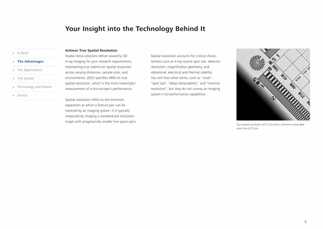
True spatial resolution of 0.7 μm and a minimum achievable voxel size of 70 nm.
Your Insight into the Technology Behind It
Achieve True Spatial Resolution
Xradia Versa solutions deliver powerful 3D
X-ray imaging for your research requirements,
maintaining true submi cron spatial resolution
across varying distances, sample sizes, and
environments. ZEISS specifies XRM on true
spatial resolution, which is the most meaningful
measurement of a microscope's performance.
Spatial resolution refers to the minimum
separation at which a feature pair can be
resolved by an imaging system. It is typically
measured by imaging a standardized resolution
target with progressively smaller line-space pairs.
Spatial resolution accounts for critical charac-
teristics such as X-ray source spot size, detector
resolution, magnification geometry, and
vibrational, electrical and thermal stability.
You will hear other terms, such as "voxel",
"spot size", "detail detectability", and "nominal
resolution", but they do not convey an imaging
system's full performance capabilities.
› In Brief
› The Advantages
› The Applications
› The System
› Technology and Details
› Service

125 µm 125 µm
7
Your Insight into the Technology Behind It
Gain An Edge In Contrast
Your imaging requires superior contrast capa-
bilities to reveal details necessary to accurately
visualize and quantify features. Xradia Versa
delivers flexible, high contrast imaging for even
your most challenging materials—low atomic
number (low Z) materials, soft tissue, polymers,
fossilized organisms encased in amber, and
other materials of low contrast.
ZEISS's comprehensive approach employs pro-
prietary enhanced absorption contrast detectors
that achieve superior contrast by maximizing
collection of low energy photons while mini-
mizing collection of contrast-reducing high
energy photons.
In addition, the tunable propagation phase
contrast measures the refraction of X-ray photons
at material transitions to allow you to visualize
features displaying little or no contrast during
absorption imaging. Now, diffraction contrast
tomography (LabDCT) reveals 3D crystallographic
information directly from polycrystalline materi-
als such as metals and alloys. This enables you
to combine crystallographic information with
absorption or phase contrast tomography where
precipitates or defects are revealed.
Pear imaged with absorption contrast – no visibility of cell walls (left), and pear imaged with phase contrast, showing details of cell walls in normal cells and stone cells (right).
LabDCT provides non-destructive 3D grain imaging for mapping orientation and microstructure (Sample: Armco Fe, diameter 1 mm. Reconstructed volume (color image), diffraction pattern (black and white image). Sample courtesy of: University of Florida; Burton R Patterson
250 µm
› In Brief
› The Advantages
› The Applications
› The System
› Technology and Details
› Service

Al
660 µm
SiO2
375 µm
Si
8
Dual Scan Contrast Visualizer (DSCoVer) Interface
Segmentation of Al particles using the 2D histogram.DSCoVer results of combined low energy (LE) and high energy (HE) XRM datasets.
Visualization and analysis of the 3D segmented Al dataset from a combined LE and HE dataset in DSCoVer. Using the 2D histogram, Al (green) and Si (brown) were segmented from the matrix over the full 3D dataset. (Sample is 3 mm in diameter)
Your Insight into the Technology Behind It
Optimize Contrast for Maximum
Discernibility
The innovative Dual Scan Contrast Visualizer
(DSCoVer) provides flexible side-by-side tuning
of two distinct tomographies. This enables
compositional probing for features normally
indistinguishable in a single scan, allowing you
to seamlessly and easily collect the data required
for dual energy analysis. Imaging a sample at two
different X-ray operating source voltages, such
as low energy (LE) or high energy (HE) or in two
different states, aligning then combining the
resulting datasets, assures you will achieve
optimum contrast for the material of interest
and enable you to define repeatable research
parameters.DSCoVer takes advantage of how
X-rays interact with matter based on effective
atomic number and density. This provides you
with a unique capability for distinguishing,
for example, mineralogical differences within
rocks as well as among difficult-to-discern
materials such as silicon and aluminum.
› In Brief
› The Advantages
› The Applications
› The System
› Technology and Details
› Service

250 µm
125 µm 125 µm
HART – 2 hours Non-HART – 4 hours
9
HART projection spacing and density optimized for feature-rich short side.
HART (left) vs without-HART 64 Gb Flash Chip. Same or better quality image in half the scan time.
Your Insight into the Technology Behind It
Achieve Higher Throughput –
Get a Faster Time to Results
The innovative High Aspect Ratio Tomography
(HART) mode on Xradia 520 Versa provides you
with higher throughput imaging for your flat
samples such as those found with semiconductor
packages and boards. HART enables you to
variably space projections so that you collect
fewer pro jections along the broad side of a flat
sample and more along the thin side. A wealth
of 3D data is provided by these closely-spaced
long views versus less densely-spaced short
views, maximizing the information density
during acquisition.
You can also tune HART to emphasize higher
throughput or better image quality, thereby
potentially accelerating image acquisition
speed by 2X.
This faster acquisition mode is in addition to a
powerful dual GPU workstation that accelerates
image reconstruction time by up to 40%.
Add the optional flat panel extension (FPX) to
achieve higher throughput (2-5X) on very large
samples (up to 10X).
› In Brief
› The Advantages
› The Applications
› The System
› Technology and Details
› Service

10
The Automated Filter Changer offers 12 standard filters with room for 12 more custom filters.
Your Insight into the Technology Behind It
Now It’s Even Easier to Image
Challenging Samples
The Automated Filter Changer (AFC) is easy to use
and facilitates features such as DSCoVer and in situ
applications on the Xradia 520 Versa instrument.
Researchers commonly use source filters to tune
the X-ray energy spectrum and every Xradia
520 Versa comes with a standard set of 12 filters.
In addition to the standard range of filters, you will
find 12 additional filter slots on the AFC to allow
you to use custom source filters, such as filters
composed of different materials or thicknesses.
The AFC houses these filters and allows your
selection to be programmed and recorded for each
recipe with the Scout-and-Scan Control System.
When you don't need a source filter at all, there
is a convenient cut-out on the AFC to allow your
samples to move even closer to the source
for higher throughput.
› In Brief
› The Advantages
› The Applications
› The System
› Technology and Details
› Service

1 mm
11
Achieve higher resolution (2X voxel) in standard field of view mode.
Image large samples such as this 6 inch stereo speaker.
Your Insight into the Technology Behind It
Flexibly Image Larger Samples
Wide Field Mode (WFM) provides you with either
an extended lateral field of view for imaging large
sample types or higher resolution using the stan-
dard field of view, both in a single tomography.
For larger samples, the lateral field of view
is approximately twice as wide as the standard
mode for the same voxel size providing you
with 3D volume more than three times larger.
Using standard field of view, WFM provides you
with nearly twice the number of voxels.
This additional imaging flexibility is available
on Xradia 520 Versa 0.4X and 4X objectives.
Combining WFM with the existing Vertical
Stitching feature, which joins separate tomogra-
phies vertically into a taller single tomography,
enables you to image large samples that are both
wider and taller than the standard field of view.
› In Brief
› The Advantages
› The Applications
› The System
› Technology and Details
› Service

12
Set, Load, Scout, Scan, Run. It’s that simple.
Your Insight into the Technology Behind It
Use Our Super Simple Control System
to Create Efficient Workflows
All of the features introduced by Xradia 520
Versa are seamlessly integrated within the
Scout-and-Scan Control System, an efficient
workflow environment that allows you to easily
scout a region of interest and specify scanning
parameters. The easy-to-use system is ideal for
a central lab-type setting where your users
may have a wide variety of experience levels.
The interface maintains the flexibility for which
Xradia Versa systems are known, enabling you
to set-up scans even more easily. Scout-and-Scan
software also offers recipe-based repeatability,
which is especially useful for your in situ and
4D research, and enables you to have greater
control and efficiency for future work.
Scout-and-Scan Advantages
• Internal camera for sample viewing
• Recipe control (set, save, recall)
• Parameter flexibility and feedback
• Multiple samples with Autoloader option
• Stitch multiple volumes easily with vertical stitch
• Micropositioning capability with a simple
mouse click
› In Brief
› The Advantages
› The Applications
› The System
› Technology and Details
› Service

250 µm
13
Expand Your Possibilities
LabDCT – Unlocking Crystallgraphic
Information in your Lab
With LabDCT, ZEISS brings you the first-ever
laboratory-based diffraction contrast tomography
imaging module. This unique grain imaging
analytical technology enables non-destructive
mapping of orientation and microstructure in 3D.
No longer confined to conventional 2D metallo-
graphy investigations, direct visualization of 3D
crystallographic grain orientation opens up a new
dimension in the characterization of metal alloys
and polycrystalline materials.
• Investigate microstructure evolution with 4D
imaging experiments: LabDCT extends metals
research to 3D—and on to 4D with routine
tool access for longitudinal studies such as
corrosion. Compared to the synchrotron, being
able to expose your samples to environments
in the microscope across days, weeks or even
months is a unique strength of laboratory-
based XRM experiments.
• Complement your grain imaging with 3D grain
morphology: Routinely acquire grain statistics
on larger volumes at faster acquisition times.
Crystallographic information provided by
LabDCT lets you supplement other analyses
like EBSD or synchrotron methods.
• Combine 3D grain orientation with 3D micro-
structural features such as defects or precipi-
tates you have observed in tomography:
Where absorption or phase contrast tomo-
graphy lack information on grain orientation
or other details of your material’s microstruc-
ture, you can combine them with LabDCT.
You will see new possibilities for characterizing
damage, deformation and growth mecha-
nisms—or even to couple with modeling.
Direct visualization of an aluminum-copper (Al – Cu) alloy, acquired with LabDCT. The 3D crystallographic information of the Al – Cu grain boundaries (a) is combined with the information of the grain shape (b) in an overlay: (c) a virtual cross-section through the center of the 3D XRM image data stack is a combination of both (a) and (b).
a
b
c
› In Brief
› The Advantages
› The Applications
› The System
› Technology and Details
› Service
Source
Aperture
Sample
Detector
L
L
Beamstop
14
Expand Your Possibilities
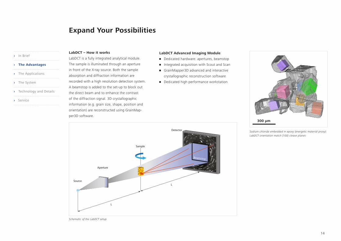
LabDCT – How it works
LabDCT is a fully integrated analytical module.
The sample is illuminated through an aperture
in front of the X-ray source. Both the sample
absorption and diffraction information are
recorded with a high resolution detection system.
A beamstop is added to the set-up to block out
the direct beam and to enhance the contrast
of the diffraction signal. 3D crystallographic
information (e.g. grain size, shape, position and
orientation) are reconstructed using GrainMap-
per3D software.
Sodium chloride embedded in epoxy (energetic material proxy): LabDCT orientation match {100} cleave planes
Schematic of the LabDCT setup.
LabDCT Advanced Imaging Module
• Dedicated hardware: apertures, beamstop
• Integrated acquisition with Scout and Scan
• GrainMapper3D advanced and interactive
crystallographic reconstruction software
• Dedicated high performance workstation
300 µm
Beamstop
› In Brief
› The Advantages
› The Applications
› The System
› Technology and Details
› Service

Click here to view this video
15
Autoloader option enables you to program up to 14 samples at a time to run sequentially.
Expand Your Possibilities
Increase Your Sample Handling Efficiency
Maximize your instrument’s utilization by
minimizing user intervention with the optional
Autoloader, available for all instruments in the
ZEISS Xradia Versa series of submicron 3D X-ray
microscopes. Reduce the frequency of user
interaction and increase productivity by enabling
multiple jobs to run. Load up to 14 samples,
queue, and allow to run all day, or off-shift.
The software provides you with the flexibility
to re-order, cancel and stop the queue to insert
a high priority sample at any time. An e-mail
notification feature in the Scout-and-Scan user
interface provides timely updates on queue
progress. Autoloader also enables a workflow
solution for high volume repetitive scanning of
like samples.
› In Brief
› The Advantages
› The Applications
› The System
› Technology and Details
› Service
16
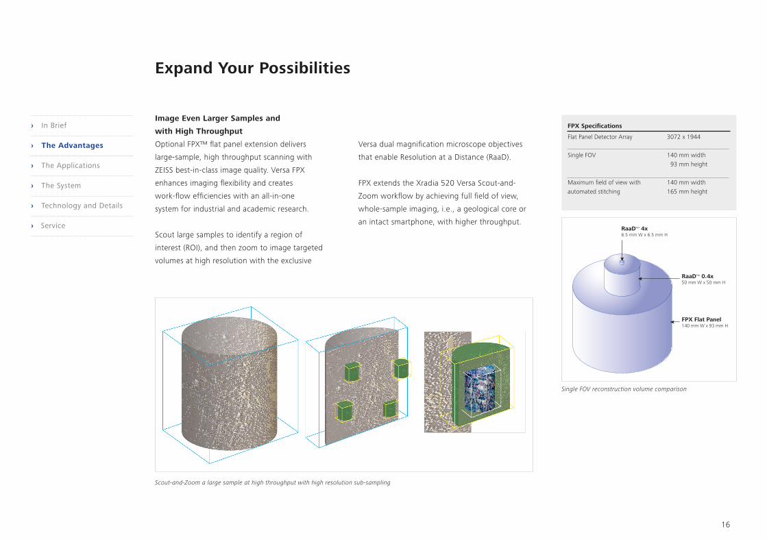
Single FOV reconstruction volume comparison
Scout-and-Zoom a large sample at high throughput with high resolution sub-sampling
Expand Your Possibilities
Image Even Larger Samples and
with High Throughput
Optional FPX™ flat panel extension delivers
large-sample, high throughput scanning with
ZEISS best-in-class image quality. Versa FPX
enhances imaging flexibility and creates
work-flow efficiencies with an all-in-one
system for industrial and academic research.
Scout large samples to identify a region of
interest (ROI), and then zoom to image targeted
volumes at high resolution with the exclusive
Versa dual magnification microscope objectives
that enable Resolution at a Distance (RaaD).
FPX extends the Xradia 520 Versa Scout-and-
Zoom workflow by achieving full field of view,
whole-sample imaging, i.e., a geological core or
an intact smartphone, with higher throughput.
FPX Specifications
Flat Panel Detector Array 3072 x 1944
Single FOV 140 mm width 93 mm height
Maximum field of view with 140 mm widthautomated stitching 165 mm height
› In Brief
› The Advantages
› The Applications
› The System
› Technology and Details
› Service

A B C D
2 cm
1 cm 100 µm100 µm
5 mm 0.5 mm
1 mm
17
FPX 0.4X 4X
Three-stage Scout-and-Zoom workflow. Rapidly scan large field of view with FPX and then zoom to regions of interest with RaaD objectives. Sample set: bear jaw, 15 cm long
A) FPX scout scan (board side view of level 2 interconnect); B) FPX scout of processor module, XY virtual plane of package-on-package construction. C) Zoom at high resolution to XZ-virtual cross-section. D) High resolution XY plane showing interconnect quality.
Expand Your Possibilities
Scout-and-Zoom Workflows› In Brief
› The Advantages
› The Applications
› The System
› Technology and Details
› Service

200 µm
18
Tension = 50 N Tension = 140 N Tension = 186 N
Making the industry’s best in situ solution even better: in situ kit tracking with Deben thermomechanical stage
Tensile testing of a steel laser weld under increasing load. The data reveal a crack initiating and propagating from a rough surface imperfection, as well as the elongation of internal voids. Sample courtesy of Sandia National Laboratories.
Expand Your Possibilities
Make Room for the Science You’ve Only
Dreamed of Until Now
Continuing to push the limits for scientific
advancement, Xradia Versa solutions have
evolved to provide you with the industry’s
premier 3D imaging solution for the widest
variety of in situ rigs, from high pressure flow
cells to tension, compression and thermal stages.
You can add the optional In Situ Interface Kit
to all Xradia Versa instruments. Contents include
a mechanical integration kit, a robust cabling
guide and other facilities (feed-throughs) along
with recipe-based software that simplifies your
operation from within the Scout-and-Scan user
interface. Experience the highest level of stability,
flexibility and controlled integration of such
in situ devices on the Xradia Versa, which
benefit from an optical architecture that
doesn’t compromise resolution in variable
environmental conditions.
› In Brief
› The Advantages
› The Applications
› The System
› Technology and Details
› Service
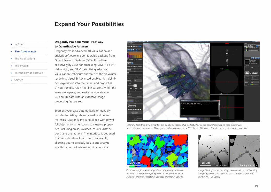
Tailor the tools that are optimal to your workflow: choose plug-ins that allow you to control registration, map differences, and customize appearance. Micro-govia-oviformis images on a ZEISS Xradia 520 Versa. Sample courtesy of Harvard University.
200 µm 25 µm
Compute morphometric properties to visualize quantitative answers. Sandstone imaged by SEM showing volume distri- bution of grains in sandstone. Courtesy of Imperial College
Image filtering: correct shading, denoise. Nickel carbide alloy imaged by ZEISS Crossbeam FIB-SEM. Dataset courtesy of P. Bala, AGH University.
19
Expand Your Possibilities
Dragonfly Pro Your Visual Pathway
to Quantitative Answers
Dragonfly Pro is advanced 3D visualization and
analysis software in a configurable package from
Object Research Systems (ORS). It is offered
exclusively by ZEISS for processing SEM, FIB-SEM,
Helium-ion, and XRM data. Using advanced
visualization techniques and state-of-the-art volume
rendering, Visual SI Advanced enables high defini-
tion exploration into the details and properties
of your sample. Align multiple datasets within the
same workspace, and easily manipulate your
2D and 3D data with an extensive image
processing feature set.
Segment your data automatically or manually
in order to distinguish and visualize different
materials. Dragonfly Pro is equipped with power-
ful object analysis functions to measure proper-
ties, including areas, volumes, counts, distribu-
tions, and orientations. The interface is designed
to intuitively interact with statistical results,
allowing you to precisely isolate and analyze
specific regions of interest within your data.
Uncorrected Shading Corrected
› In Brief
› The Advantages
› The Applications
› The System
› Technology and Details
› Service

20
Precisely Tailored to Your Applications
Typical Applications
Materials Research Characterize materials • Non-destructive views into deeply buried microstructures that may be unobservable with 2D surface imaging such as optical microscopy, SEM, and AFM; compositional contrast for studying low Z or "near Z" elements and other difficult-to-discern materials
• Ability to maintain resolution at a distance for non-destructive in situ imaging experiments in varying conditions or native-like environ ments. Fast, efficient Scout-and-Zoom technology further enhanced with Versa FPX to look at very large samples on a macro scale to determine regions of interest for high resolution imaging.
Observe fracture mechanics
Investigate properties at multiple length scales
Quantify and characterize microstructural evolution
Perform in situ and 4D (time dependent studies) to understand the impact of heating, cooling, dessication, wetting, tension, tensile compression, imbibition, drainage and other simulated environmental studies
Life Sciences Perform histologies virtually • Highest resolution and highest contrast for unstained and stained hard and soft tissues and biological microstructure
• Versa FPX Scout-and-Zoom technology to image large, intact specimens and determine ROI for high resolution study
Visualize cellular and subcellular features
Characterize centimeter to submicron structures
Expand your views in developmental biology with high resolution, high contrast images of cellular and subcellular structure
Image large intact samples such as brains or large bones
Raw Materials Characterize heterogeneity at core plug scale and quantify pore structures • The most accurate 3D submicron support for digital rock simulations, in situ multiphase fluid flow studies, 3D mineralogy, and laboratory based diffraction contrast tomography.
• Multiscale imaging, characterization and modeling of large (4" core)samples at high throughput
• LabDCT for your R&D lab
Measure fluid flow, analyze texture, understand dimensional classification
Study carbon sequestration efforts
Advance mining processes: analyze tailings to maximize mining efforts; conduct thermodynamic leaching studies; perform QA/QC analysis of mining products such as iron ore pellets
Understand grain orientations in steel and other metals
Manufacturing and Assembly Optimized process development for the Electronics, Automotive and Medical Device industries
• Single tool workflow with high throughput macro-scanning of an intact device. Non-destructively scout-and-zoom from module to package to interconnect for submicron imaging of defect re-localization and characterization with a fast time to results that complement or replaces physical cross-sectioning.
Study package reliability
Perform failure analysis
Analyze package construction
› In Brief
› The Advantages
› The Applications
› The System
› Technology and Details
› Service
150 µm
1 mm
100 µm 25 mm
100 µm
20 mm
21
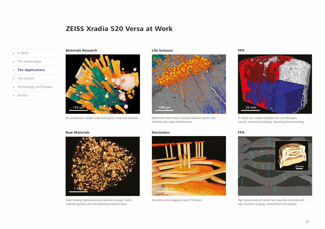
Shale showing highly absorbing materials (orange), matrix materials (yellow), and low-absorbing materials (blue)
Non-destructive imaging of open TSV failure
3D quantification of fiber reinforced polymer composite materials Mammalian brain tissue showing individual neuron cells, dendrites and single labeled neuron
4" whole core sample classified into rock lithologies, used for mechanical sampling, upscaling and downscaling
High speed survey of camera lens assembly combined with high resolution imaging, measurement and analysis
Life Sciences FPX
FPX
ZEISS Xradia 520 Versa at Work
Materials Research
Raw Materials Electronics
› In Brief
› The Advantages
› The Applications
› The System
› Technology and Details
› Service

1
211
9
10
7
6
85
4
3
22
Your Flexible Imaging Solution
1 X-ray Microscope
• ZEISS Xradia 520 Versa with Resolution at a Distance
• Dual Scan Contrast Visualizer (DSCoVer) for materials
discernment and dual energy analyses
• High Aspect Ratio Tomography (HART) for accelerated
imaging and better image quality
• Diffraction Contrast Tomography (LabDCT) option for
visualization of 3D crystallographic grain information
2 X-ray Source
• High performance, sealed transmission source
(30 – 160 kV, Maximum 10 W)
3 Detector System
• Innovative dual-stage detector system offers turret of
multiple objectives with different magnifications and
optimized scintillators for highest contrast
• 2k x 2k pixel, noise suppressed charge-coupled detector
• FPX flat panel extension for larger field of view,
high throughput macroscopic imaging (optional)
4 System Stability for Highest Resolution
• Granite base vibrational isolation
• Thermal environment stabilization
• Low noise detector
• Advanced proprietary stabilization mechanisms
5 System Flexibility for a Diverse Range
of Sample Sizes
• Variable scanning geometry
• Tunable voxel sizes
• Absorption contrast mode
• Phase contrast mode
• Wide Field Mode (WFM) for increased lateral
tomography volume with 0.4X and 4X objectives
• Vertical stitching for joining multiple tomographies
vertically
• Optional LabDCT for crystallographic information
6 Autoloader Option
• Maximize productivity by reducing user intervention
• Programmable handling of up to 14 samples
• Automated workflows for high volume, repetitive scanning
7 Sample Stage
• Ultra-high precision 4-degrees of freedom sample stage
• 25 kg sample mass capacity
8 X-ray Filters
• Automated Filter Changer (AFC) with 24 filter capacity
and cutout for highest throughput ‘no filter’ imaging
• Set of 12 filters included
• Custom filters available by special order
9 In Situ and 4D Solutions
• Resolution at a Distance (RaaD) enables superior
in situ imaging
• Integrated in situ recipe control for Deben stages
• In situ interface kit option
• Custom in situ flow interface kit by special order
10 Instrument Workstation
• Power workstation with fast reconstruction
• Dual CUDA-based GPU
• Multi-core CPU
• 24” display monitor
11 Software
• Acquisition: Scout-and-Scan Control System
• Reconstruction: XMReconstructor
• Viewer: XM3DViewer
• Compatible with wide breadth of 3D viewers and
analysis software programs
• ORS Dragonfly Pro for 3D visualization and analysis (optional)
› In Brief
› The Advantages
› The Applications
› The System
› Technology and Details
› Service

23
Technical Specifications
standard option
Imaging
Spatial Resolution 0.7 μmResolution at a Distance (RaaD)* at 50 mm working distance 1.0 µmMinimum Achievable Voxel** (Voxel size at sample at maximum magnification) 70 nm
* RaaD working distance defined as clearance around axis of rotation** Voxel (sometimes referred to as “nominal resolution” or “detail detectability”) is a geometric term that contributes to but does not determine resolution, and is provided here only for comparison. ZEISS specifies on spatial resolution, the most meaningful measurement of instrument resolution.
X-ray Source for Xradia 510 Versa & Xradia 520 Versa
Type Sealed transmissionTube Voltage Range 30 – 160 kVMaximum Output 10 WRadiation Safety (measured 25 mm above surface of enclosure) < 1 μS/hr (equivalent to 0.10 mRem/hr)
Detector System
ZEISS X-ray microscopes feature an innovative detector turret with multiple objectives at different magnifications. Each objective features optimized scintillators that deliver the highest absorption contrast details.Standard Objectives 0.4X, 4X, 20XOptional Objectives 40XOptional Detector Flat Panel Extension (FPX)
Stages
Sample Stage (load capacity) 25 kgSample Stage Travel (x, y, z) 45, 100, 50 mmStage Travel (rotation) 360ºSource Travel (z) 190 mmDetector Travel (z) 290 mmSample Size Limit 300 mm
Feature Comparison ZEISS Xradia 520 Versa ZEISS Xradia 510 Versa ZEISS Xradia 410 Versa
Scout-and-Scan Control System Automated Filter Changer
High Aspect Ratio Tomography
DSCoVer Dual Scan Contrast Visualizer
Absorption Contrast
Phase Contrast
FPX Flat Panel ExtensionLabDCT Diffraction Contrast TomographyAutoloaderWide Field Mode 0.4X and 4X 0.4X 0.4XVertical Stitching
GPU CUDA-based Reconstruction Dual Single SingleIn Situ Interface Kit
› In Brief
› The Advantages
› The Applications
› The System
› Technology and Details
› Service
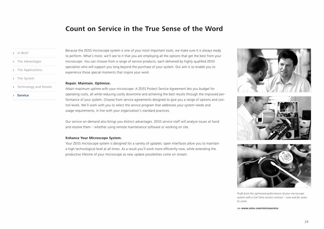
Because the ZEISS microscope system is one of your most important tools, we make sure it is always ready
to perform. What’s more, we’ll see to it that you are employing all the options that get the best from your
microscope. You can choose from a range of service products, each delivered by highly qualified ZEISS
specialists who will support you long beyond the purchase of your system. Our aim is to enable you to
experience those special moments that inspire your work.
Repair. Maintain. Optimize.
Attain maximum uptime with your microscope. A ZEISS Protect Service Agreement lets you budget for
operating costs, all while reducing costly downtime and achieving the best results through the improved per-
formance of your system. Choose from service agreements designed to give you a range of options and con-
trol levels. We’ll work with you to select the service program that addresses your system needs and
usage requirements, in line with your organization’s standard practices.
Our service on-demand also brings you distinct advantages. ZEISS service staff will analyze issues at hand
and resolve them – whether using remote maintenance software or working on site.
Enhance Your Microscope System.
Your ZEISS microscope system is designed for a variety of updates: open interfaces allow you to maintain
a high technological level at all times. As a result you’ll work more efficiently now, while extending the
productive lifetime of your microscope as new update possibilities come on stream.
Profit from the optimized performance of your microscope system with a Carl Zeiss service contract – now and for years to come.
Count on Service in the True Sense of the Word
>> www.zeiss.com/microservice
24
› In Brief
› The Advantages
› The Applications
› The System
› Technology and Details
› Service

Not
for
med
ical
dia
gnos
tic, t
hera
peut
ic o
r tr
eatm
ent
purp
oses
. Not
all
prod
ucts
are
ava
ilabl
e in
eve
ry c
ount
ry. C
onta
ct y
our
loca
l ZEI
SS r
epre
sent
ativ
e fo
r m
ore
info
rmat
ion.
EN_4
2_01
1_07
4 | C
Z 10
-201
7 | D
esig
n, s
cope
of d
eliv
ery
and
tech
nica
l pro
gres
s su
bjec
t to
chan
ge w
ithou
t not
ice.
| ©
Car
l Zei
ss M
icro
scop
y G
mbH
Carl Zeiss Microscopy GmbH 07745 Jena, Germany [email protected] www.zeiss.com/520-versa


