83
Version 4.1 Chp. 9: Troubleshooting CCNA Discovery 2
| Date post: | 23-Dec-2015 |
| Category: |
Documents |
| Upload: | lindsay-clarke |
| View: | 226 times |
| Download: | 0 times |
Version 4.1
Chp. 9: Troubleshooting
CCNA Discovery 2

Contents
•9.1: Troubleshooting approaches •9.2: Troubleshooting Layer 1 and 2•9.3: Troubleshooting Layer 3 IP
Addressing•9.4: Troubleshooting Layer 3 Routing•9.5: Troubleshooting Layer 4 & Upper
Layers
Troubleshooting by Layers
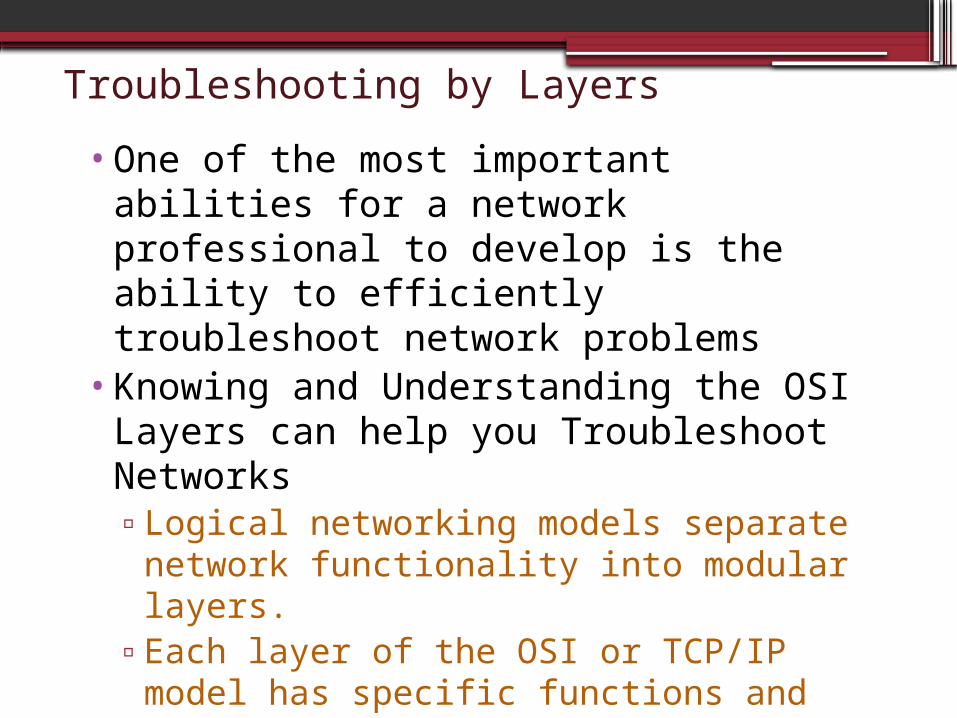
•One of the most important abilities for a network professional to develop is the ability to efficiently troubleshoot network problems
•Knowing and Understanding the OSI Layers can help you Troubleshoot Networks▫Logical networking models separate
network functionality into modular layers. ▫Each layer of the OSI or TCP/IP model
has specific functions and protocols.
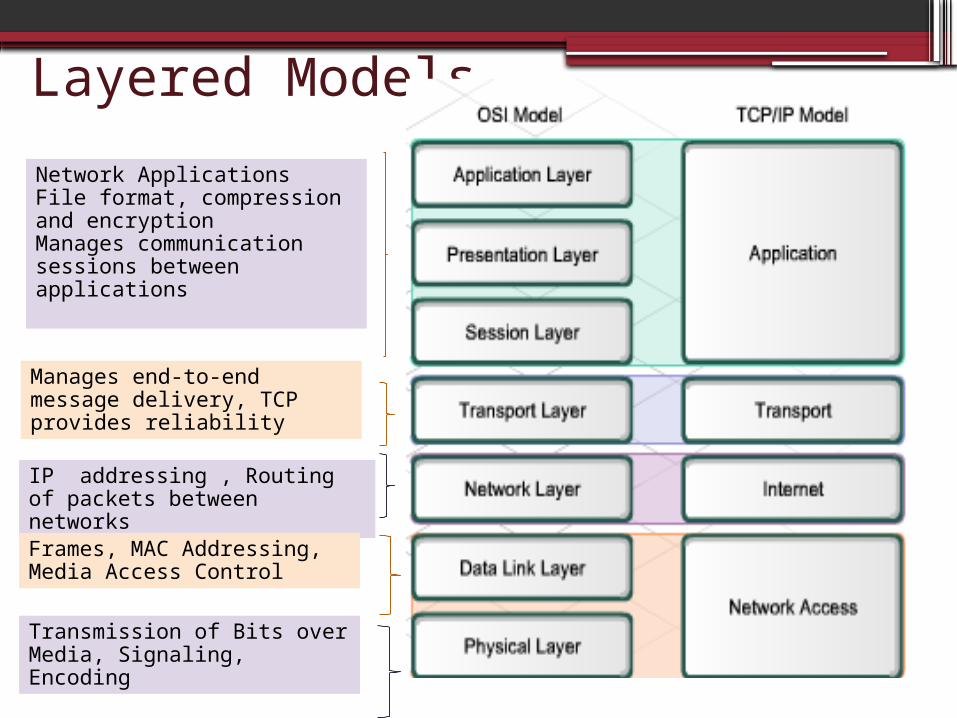
Layered Models
Network ApplicationsFile format, compression and encryptionManages communication sessions between applications
Manages end-to-end message delivery, TCP provides reliability
IP addressing , Routing of packets between networks
Frames, MAC Addressing, Media Access Control
Transmission of Bits over Media, Signaling, Encoding
Upper Layer Errors•The upper layers (5-7) of the OSI model
deal with specific application functionality and are generally implemented only in software.
•Problems in the Upper Layers (5 to 7) are frequently be caused by software configuration errors on clients and servers
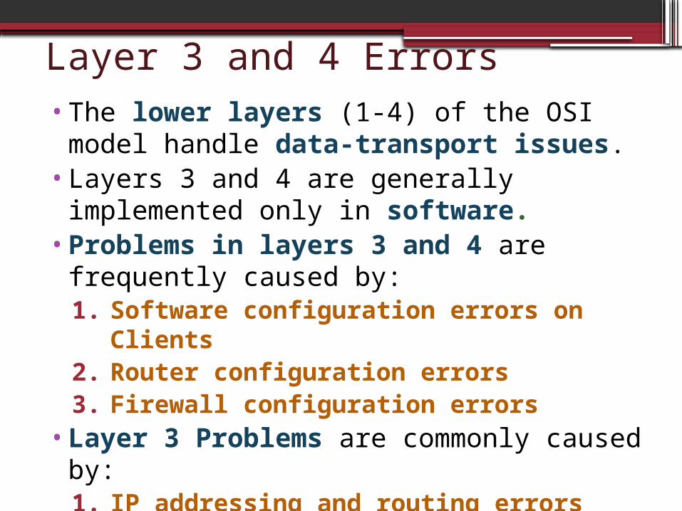
Layer 3 and 4 Errors•The lower layers (1-4) of the OSI model
handle data-transport issues.•Layers 3 and 4 are generally implemented
only in software. •Problems in layers 3 and 4 are
frequently caused by:1. Software configuration errors on
Clients2. Router configuration errors 3. Firewall configuration errors
•Layer 3 Problems are commonly caused by:1. IP addressing and routing errors

Layer 1 and 2 Errors•Layer 1 and Layer 2 are implemented in
both hardware and software. •The Physical Layer is closest to the
physical network medium, such as the network cabling, and is responsible for actually placing information on the medium.
•Most problems in Layer 1 and Layer 2 are caused by:1. Hardware problems 2. Hardware incompatibilities
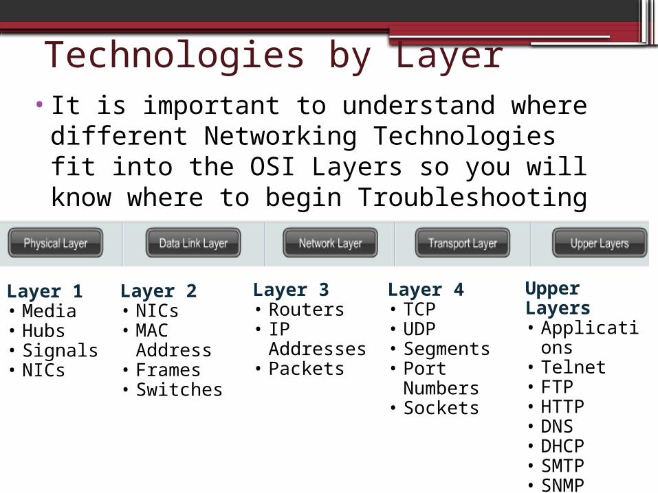
Technologies by Layer•It is important to understand where
different Networking Technologies fit into the OSI Layers so you will know where to begin Troubleshooting
Layer 1• Media• Hubs• Signals• NICs
Layer 2• NICs• MAC Address• Frames• Switches
Layer 3• Routers• IP
Addresses• Packets
Layer 4• TCP• UDP• Segments• Port
Numbers• Sockets
Upper Layers• Applications• Telnet• FTP• HTTP• DNS• DHCP• SMTP• SNMP
Troubleshooting Approaches•There are 3 main troubleshooting approaches when using network models:1. Top-down2. Bottom-up3. Divide-and-conquer
•Using one of these troubleshooting methods, a troubleshooter can verify all functionality at each layer until the problem is located and isolated.

Top-down •The Top-down approach starts with the
Application Layer and works down. • It looks at the problem from the point of
view of the user and the application. •Is it just one application that is not
functioning, or do all applications fail? •For example:
▫Can the user access various web pages on the Internet, but not email?
▫Do other workstations have similar issues? •Suitable for simpler problems or those
where an application error is suspected
Bottom-up•The Bottom-up approach starts with the
Physical Layer and works up. •The Physical Layer is concerned with
hardware and wire connections. ▫Are cables securely connected? ▫If the equipment has indicator lights, are
those lights on or off?•Suitable for more complex problems•Slow, but solid method
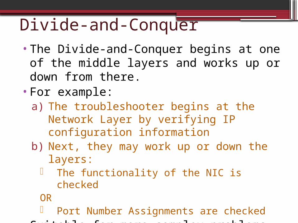
Divide-and-Conquer•The Divide-and-Conquer begins at one of
the middle layers and works up or down from there.
•For example:a) The troubleshooter begins at the Network
Layer by verifying IP configuration information
b) Next, they may work up or down the layers:
The functionality of the NIC is checkedOR Port Number Assignments are checked
•Suitable for more complex problems and when the problem has less precise symptoms
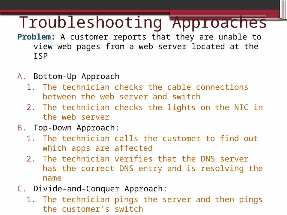
Troubleshooting ApproachesProblem: A customer reports that they are unable to view
web pages from a web server located at the ISP
A. Bottom-Up Approach1. The technician checks the cable connections between
the web server and switch2. The technician checks the lights on the NIC in the web
serverB. Top-Down Approach:
1. The technician calls the customer to find out which apps are affected
2. The technician verifies that the DNS server has the correct DNS entry and is resolving the name
C. Divide-and-Conquer Approach:1. The technician pings the server and then pings the
customer’s switch2. The technician checks the firewall configuration
Troubleshooting Tools•It is very difficult to troubleshoot any type
of network connectivity issue without a network diagram that depicts the IP addresses, IP routes, and devices, such as firewalls and switches.
•Logical and physical topologies are extremely useful in troubleshooting.

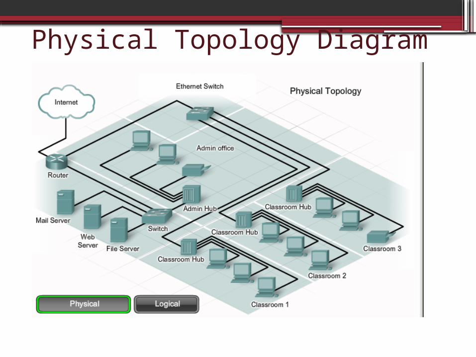
Physical Network Topology• A physical network topology shows the
physical layout of the devices connected to the network.▫Knowing how devices are physically connected
is necessary for troubleshooting problems at the Physical Layer, such as cabling or hardware problems.
• Physical network topologies typically include:▫Device types▫Models and manufacturers of devices▫Locations▫Operating system versions▫Cable types and identifiers▫Cabling endpoints
Physical Topology Diagram

Logical Network Topology• A logical network topology shows how data is
transferred on the network. ▫Symbols are used to represent network
elements such as routers, servers, hubs, hosts, and security devices.
• Logical network topologies typically include: ▫Device identifiers ▫IP addresses and subnet masks▫Interface identifiers▫Routing protocols▫Static and default routes▫Data-link protocols▫WAN technologies

Logical Topology Diagram

Troubleshooting tools•In addition to network diagrams, other
tools may be needed to effectively troubleshoot network performance issues and failures.▫Documentation and baseline tools
To create network diagrams and document hardware
▫Management system tools To monitor network performance
▫Knowledge bases Network device vendor knowledge bases are
an indispensable sources of information.▫Protocol analyzers
Decodes the protocol layers in a recorded frame and presents the information in an easy-to-use format.

Troubleshooting Hardware Tools
Sometimes failures in the lower layers of the OSI model must be identified with hardware troubleshooting tools:▫Cable testers
Handheld devices designed for testing data communication cabling for broken wires, crossed-over wiring, shorted connections, and improperly paired connections
▫Digital multimeters Test instruments that measure electrical values of
voltage, current, and resistance.
▫Portable network analyzers For testing network traffic utilization
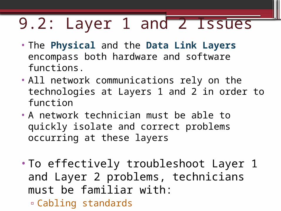
9.2: Layer 1 and 2 Issues• The Physical and the Data Link Layers
encompass both hardware and software functions.
• All network communications rely on the technologies at Layers 1 and 2 in order to function
• A network technician must be able to quickly isolate and correct problems occurring at these layers
•To effectively troubleshoot Layer 1 and Layer 2 problems, technicians must be familiar with:▫Cabling standards▫Encapsulation ▫Framing
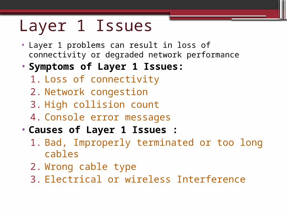
Layer 1 Issues• Layer 1 problems can result in loss of connectivity or
degraded network performance
• Symptoms of Layer 1 Issues:1. Loss of connectivity2. Network congestion3. High collision count4. Console error messages
• Causes of Layer 1 Issues :1. Bad, Improperly terminated or too long
cables2. Wrong cable type3. Electrical or wireless Interference
See Troubleshooting chart

Troubleshoot Layer 1 Issues• Most layer 1 issues are caused by
Hardware problems and incompatibilities
•To Troubleshoot Layer 1 Issues:1. Visually Inspect Cables2. Check Hardware Configurations3. Use Show Interfaces to check Interface
statistics4. Monitor Network Performance
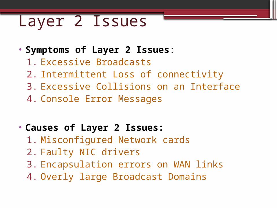
Layer 2 Issues
• Symptoms of Layer 2 Issues:1. Excessive Broadcasts2. Intermittent Loss of connectivity3. Excessive Collisions on an Interface4. Console Error Messages
• Causes of Layer 2 Issues:1. Misconfigured Network cards2. Faulty NIC drivers3. Encapsulation errors on WAN links4. Overly large Broadcast Domains
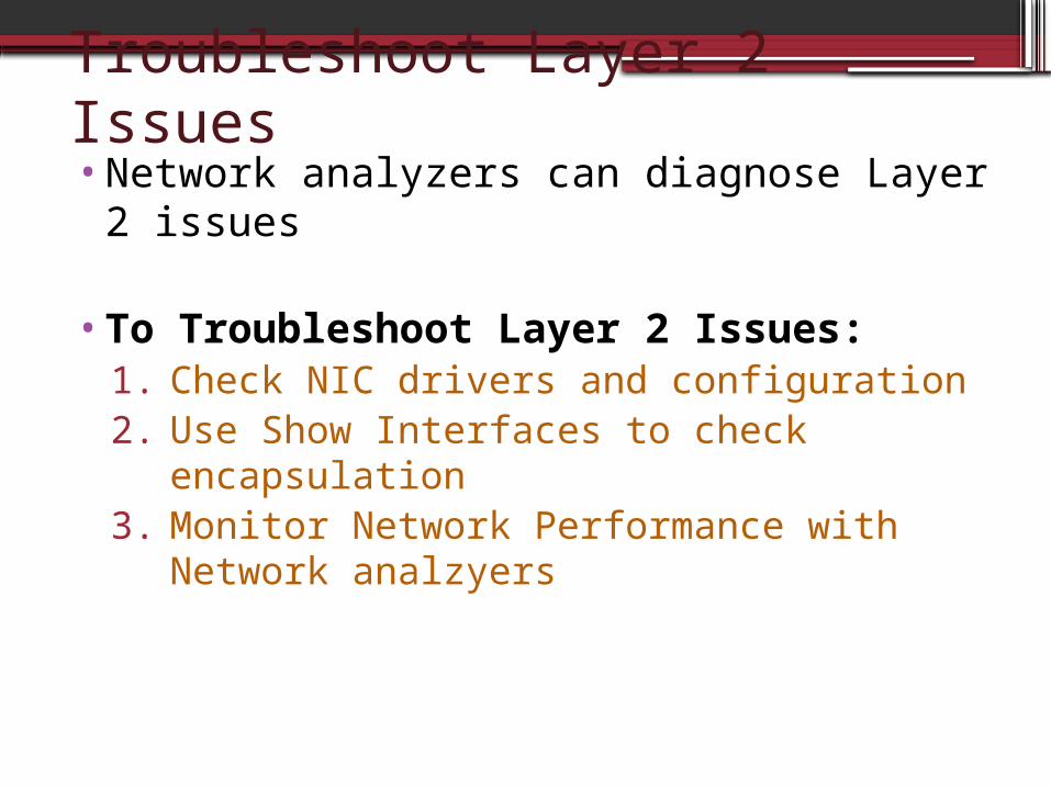
Troubleshoot Layer 2 Issues•Network analyzers can diagnose Layer 2
issues
•To Troubleshoot Layer 2 Issues:1. Check NIC drivers and configuration2. Use Show Interfaces to check
encapsulation3. Monitor Network Performance with
Network analzyers

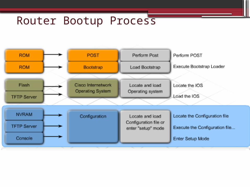
Router Bootup• To troubleshoot device hardware failures and boot
errors, you must understand the Router Boot Process:
1. Perform the POST and load the bootstrap program.
▫ tests the router hardware▫ After POST, the bootstrap program is loaded ▫ The Bootstrap program is loaded from ROm
2. Locate and load the Cisco IOS software▫ IOS is located from: flash memory (default), a TFTP server,
or router Boots into ROMmon Mode and loaded into RAM▫ The IOS locates the hardware and software components
and lists the results on the console terminal
3. Locate and load the startup configuration file or enter setup mode
▫ Config file is loaded from: NVRAM, a TFTP server, or the router enters into setup mode
▫ This starts routing processes and supplies addresses to interfaces
Router Bootup Process
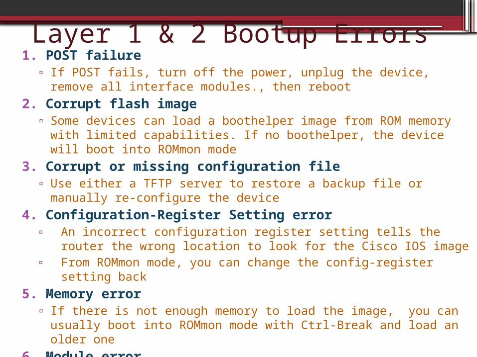
Layer 1 & 2 Bootup Errors1. POST failure
▫ If POST fails, turn off the power, unplug the device, remove all interface modules., then reboot
2. Corrupt flash image▫ Some devices can load a boothelper image from ROM memory with
limited capabilities. If no boothelper, the device will boot into ROMmon mode
3. Corrupt or missing configuration file▫ Use either a TFTP server to restore a backup file or manually re-
configure the device
4. Configuration-Register Setting error▫ An incorrect configuration register setting tells the router the
wrong location to look for the Cisco IOS image▫ From ROMmon mode, you can change the config-register setting
back
5. Memory error▫ If there is not enough memory to load the image, you can usually
boot into ROMmon mode with Ctrl-Break and load an older one
6. Module error▫ Faulty or improperly seated interface modules may not be
recognized during the POST and Cisco IOS load. Remove them and reboot
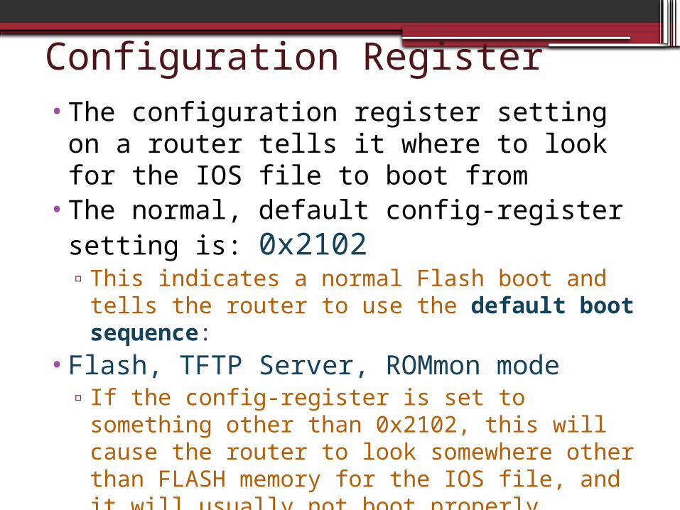
Configuration Register•The configuration register setting on a
router tells it where to look for the IOS file to boot from
•The normal, default config-register setting is: 0x2102▫This indicates a normal Flash boot and tells the
router to use the default boot sequence: •Flash, TFTP Server, ROMmon mode
▫If the config-register is set to something other than 0x2102, this will cause the router to look somewhere other than FLASH memory for the IOS file, and it will usually not boot properly

Viewing the Config-Register•Once a router is booted, the ONLY
command that can be used to view the config-register is show version▫Router# show version

ROMmon Mode• If a router fails to boot a valid IOS file, it will
boot up in ROM monitor (ROMmon) mode• ROMmon software is a simple command set
stored in read only memory (ROM) • It can be used to troubleshoot boot errors and
recover the router when the IOS is not present•Troubleshooting in ROMmon mode:
1. Look in flash memory for a valid IOS image
rommon 1> dir flash:2. Once an IOS image is found, boot the
image manually rommon 1> boot flash:<IOS filename>
Troubleshooting Boot Errors
•In order to troubleshoot Router bootup errors:1. Observe console messages during the
boot sequence
2. Use the show commands to verify operational status
When boot problems cause a network outage, use substitution to replace the device with a known good device to restore services to end users

Troubleshoot Boot Errors • Show version
▫ displays the version of the operating system and whether all interface hardware is recognized.
• Show flash ▫ displays the contents of the Flash memory,
including the Cisco IOS image file. It also displays the amount of Flash memory currently being used and the amount of memory available.
• Show ip interfaces brief ▫ shows the operational status of the device
interfaces and IP addresses assigned. • Show running-configuration and show
startup-configuration▫ verify whether all the configuration commands
were recognized during boot

Layer 1 & 2 Router Interface Errors•Router Interface errors are often the
first symptom of Layer 1 and Layer 2 cabling or connectivity errors
•Causes of Layer 1 Interface errors:1. Cable Errors2. Physical Interface Errors3. Hardware Errors
•Causes of Layer 2 Interface Errors:1. Encapsulation Error2. Clock Rate Error3. Misconfigured IP Address4. Interface not Enabled

Interface Issues
The interface cannot detect any signal on the line – due to a bad cable, no cable, interface error, or failed CSU/DSU on a serial interface
There is an encapsulation error, a missing clock rate, misconfigured IP Address or the interface is not receiving keepalives
The Interface is disabled due to hardware errors
The Interface has not been enabled with the no shutdown command
Layer 1 Issues
Layer 2 Issues

Layer 1 & 2 Interface Media Errors
•4 different types of Layer 1 and 2 Media Errors that can exist on a router interface▫Excessive noise ▫Excessive collisions▫Excessive runts▫Late collisions

Excessive Noise
• The Interface shows many CRC errors but not many collisions
• Usually indicates a media or cable error• Common causes are electrical interference, loose
or damaged connections, or incorrect cabling type

Excessive Collisions
•Can only occur on half-duplex or shared-media Ethernet connections (when hubs in use)
•Can be caused by Damaged cables
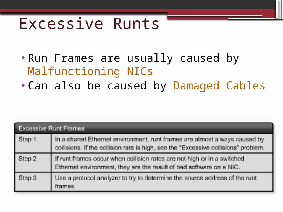
Excessive Runts
•Run Frames are usually caused by Malfunctioning NICs
•Can also be caused by Damaged Cables
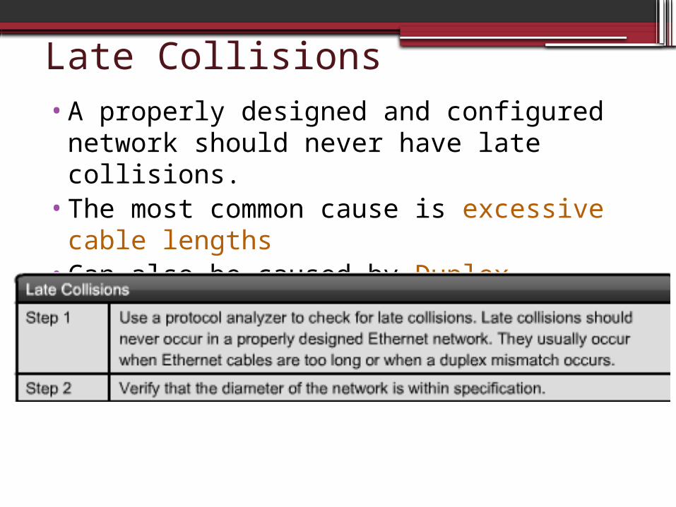
Late Collisions•A properly designed and configured
network should never have late collisions. •The most common cause is excessive
cable lengths•Can also be caused by Duplex mismatches
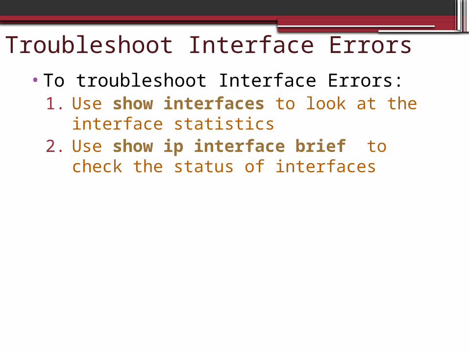
Troubleshoot Interface Errors•To troubleshoot Interface Errors:
1. Use show interfaces to look at the interface statistics
2. Use show ip interface brief to check the status of interfaces
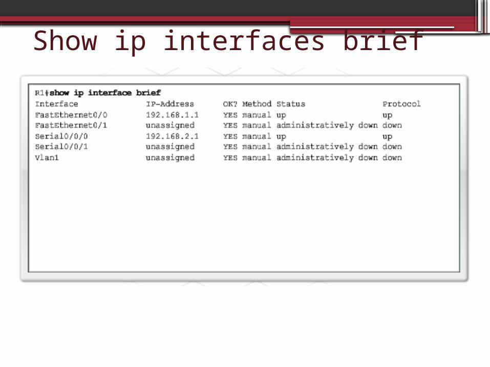
Show ip interfaces brief

Layer 2: LAN Connectivity ErrorsLAN troubleshooting usually centers around
switches, because the majority of LAN users connect to the network via switch ports.
• Causes of LAN Connectivity Errors:1. Port hardware failures2. Cable errors3. Ports not Enabled4. Duplex and/or Speed Mismatch

LAN Connectivity TroubleshootingSwitch Troubleshooting:1. Observe port LEDs to verify port functionality
▫ Red or orange indicates an error
2. Verify cable connections3. Verify configuration to ensure ports are
enabled▫ Switch# show run▫ Switch# show interfaces
4. Verify duplex settings on ports▫ Switch# show interface port status
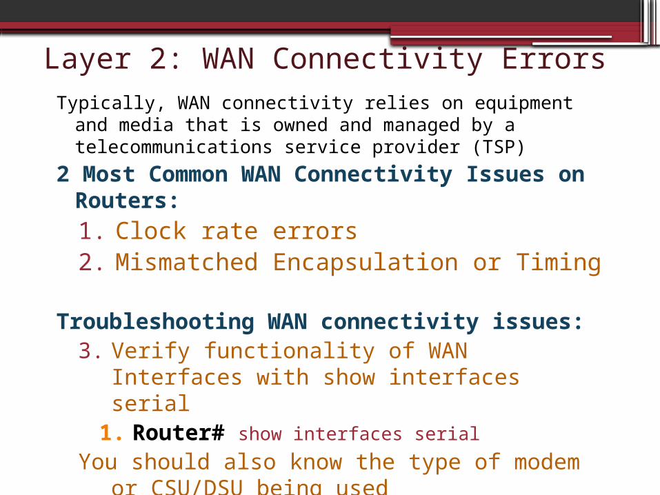
Layer 2: WAN Connectivity ErrorsTypically, WAN connectivity relies on equipment and
media that is owned and managed by a telecommunications service provider (TSP)
2 Most Common WAN Connectivity Issues on Routers:1. Clock rate errors2. Mismatched Encapsulation or Timing
Troubleshooting WAN connectivity issues:3. Verify functionality of WAN Interfaces with
show interfaces serial1. Router# show interfaces serial
You should also know the type of modem or CSU/DSU being used

9.3: Layer 3 Issues•Layer 3 Issues are largely due to poorly
designed and configured IP addressing schemes▫At Layer 3, each packet must be identified
with the source and destination addresses of the two end systems.
▫A device must be configured with an IP address to exchange messages using TCP/IP
•To troubleshoot Layer 3 problems, you must be able to:▫Determine the range of host addresses that
belong to each individual IP network or subnet

Subnetting Example• The Network 192.168.1.0 /24 needs to be
subnetted to create 6 usable Subnets ▫Class: C▫Default Subnet Mask:
255.255.255.0▫# of Bits to borrow : 3
Total Subnets Created: 8 2 X (x = bits borrowed)
Usable Subnets Created: 6 2 X - 2 (x = bits borrowed)
Total Host Addresses per Subnet: 32 2 y (y = host bits left over)
Usable Host Addresses per Subnet: 30 2 y - 2 (y = host bits left over)

Subnetting Example
Not Usable
Not Usable
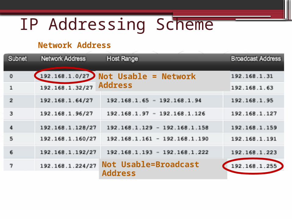
IP Addressing Scheme
Not Usable = Network Address
Not Usable=Broadcast Address
Network Address

Subnet PracticeGiven the Network Address and Subnet Mask, Define: 1. The Range of Host Addresses2. The Broadcast Address 3. The Next Network Address
10 244 30
10 244 3010 244 30
10 244 30
10 244 30 228
255 255 255 252
252= 11111100Place value of last bit borrowed = 4Subnets Increase by a value of 4:
Go to Section: 9.3.1.3 in Discovery 2 to Practice this Activity
Layer 3 IP Design Issues•Common Layer 3 Problems caused by
Poor Address Design and Planning1. Overlapping subnets
When the address range of two separate subnets includes some of the same host or broadcast addresses
The Router IOS does not allow you to configure overlapping subnets on multiple interfaces of the same device
However, it will allow you to configure overlapping subnets on different devices, which will cause problems
2. Misconfigured subnet masks On Hosts and routers
3. Insufficient addresses available through DHCP
If the subnetting design does not allow for enough available host addresses, then the DHCP server will not be able to assign them

Overlapping Subnets
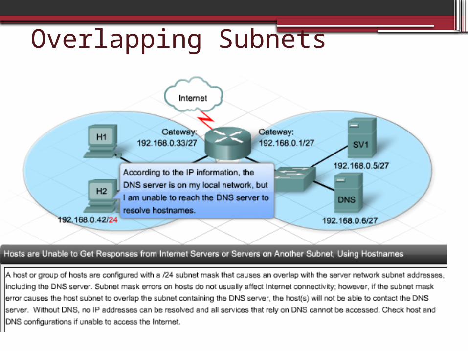
Overlapping Subnets

Misconfigured Subnet Mask
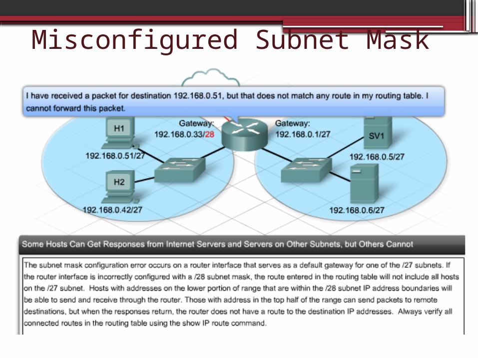
Misconfigured Subnet Mask

Insufficient addresses available
•If the IP subnetting scheme does not allow for enough host addresses in each subnet, some hosts will be unable to receive an IP address from the DHCP server.▫When a host can not receive an address
from a DHCP server, it automatically assigns itself an address on the 169.254.0.0 network.
▫ A duplicate IP address Error can also occur on a host
▫ Use the show ip dhcp binding command from the command prompt to check whether the DHCP server has available addresses

Determine # of Hosts Available
62
Go to Section: 9.3.3.2 in Discovery 2 to Practice this Activity

9.4: Layer 3 Routing issues•Common Symptoms of Layer 3
Routing Errors: 1. Network failures 2. Poor network performance
•Routing problems are usually the result of :1. Static (manual) route entry errors2. Routing protocol configuration errors3. Routing Protocol operation errors▫They can also be caused by failures at the
lower layers of the OSI model

Interpreting the Routing Table• When there is a change in the network status,
routes can be lost, or an incorrect route can be installed into the routing table.
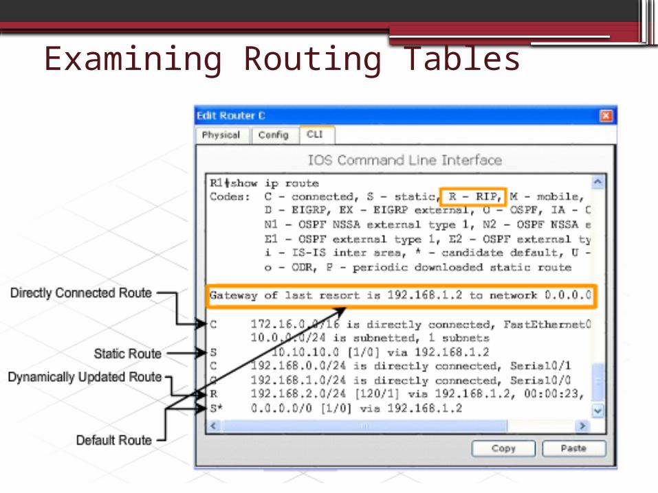
• The primary tool to use when troubleshooting Layer 3 routing problems is examining the Routing Table▫ Router: Show ip route
• The routing table consists of route entries from the following sources:▫ Directly connected networks▫ Static routes▫ Dynamic routing protocols
• Any time a routing problem is suspected, use the show ip route command to ensure that all the expected routes are installed in the routing table.
Examining Routing Tables

Connected Routes• Connected Route Problems
▫ Directly connected routes are automatically installed in the routing table when an IP address is configured on an interface, and the interface is enabled using the no shutdown command.
• Causes of Connected Route Problems1. An Interface has an invalid IP Address2. An Interface is not enabled
• Troubleshooting Connected Routes1. Use the show interfaces or show ip
interface brief command to verify that the Interface is UP and has a valid IP address

Static and Default Routes• Static and Default Route Problems
▫ Static and default routes must use either an exit interface on the router or the IP address of the next hop router.
• Causes of Problems▫ When a static or default route does not appear in the
routing table, the problem is most likely a configuration error.
1. If the next hop address is not in the correct IP address range of a directly connected network, then the route will not be vaild
• Troubleshooting Static and Default Routes1. Verify that the configuration statements are correct
with the show run command2. Verify that the exit interfaces used by the routes are in
an up/up state with the show ip interfaces brief command

Dynamic Routes• Dynamic Route Problems
▫ Dynamic Routes are learned from other routers through the use of routing protocols
▫ In order for dynamic routes to be correct, the routing protocol must be operating properly
• Causes of Dynamic Route Problems▫ A missing route could be caused by a misconfiguration
on one or more of the routers on the path to the destination.
1. Missing Network Statements in the Routing Protocol configuration of another router can cause dynamic routes to not be advertised properly
• Troubleshooting Dynamic Routes1. Use show ip protocols to check the configuration of
routing protocols2. Use show run to check the routing protocol
configuration3. Use show ip interfaces brief to view interface status4. Use the debug ip rip command to verify routing
updates
Layer 3 RIP Issues
•Issues related specifically to RIP:1. RIP Version mismatch between routers2. Incorrect or missing network statements

RIP Network Statement•When configuring RIP, the network
statement does two things:1. It enables the routing protocol to send
and receive updates on all the local interfaces that belong to that network.
2. It includes that network in its routing updates to its neighboring routers.
•A missing or incorrect network statement results in inaccurate routing updates and can prevent an interface from sending or receiving routing updates.

RIP Configuration

Troubleshooting RIP issues
Tools for troubleshooting dynamic routing issues:
1. Use TCP/IP utilities to test connectivity ▫ Ping to test connectivity▫ Traceroute to test connectivity▫ Telnet to verify connectivity and make
configuration changes.2. Use Debug commands to view updates
▫ Debug ip rip – to view RIP updated in real-time
3. Use Show commands to verify configuration & routes
Show run –view version and network statements
Show ip protocols – view rip configurationShow ip interfaces – view interface statusShow ip route – view routesShow interfaces – view interface status

Debug ip rip

9.5: Troubleshooting Layer 4 Issues•Layer 4 is responsible for transporting
data packets and specifies the port number used to reach specific applications.
•Layer 4 network problems can arise at the edge of the network where security technologies are examining and modifying the traffic.
•Many problems at Layer 4 are caused by misconfigured firewalls, which might deny traffic based on port numbers, even though this traffic should be forwarded.

Layer 4 Issues•Symptoms of Layer 4 problems:
1. Security problems2. Intermittent network problems3. Trouble using some services
•Causes of Layer 4 Problems 1. Firewall misconfiguration
Example: ftp active connections blocked
2. Incorrect port assignments for applications

Well Known Port Numbers
21

Upper Layer Issues• Most of the upper layer protocols provide user services
that are typically used for network management, file transfer, distributed file services, terminal emulation, and email.▫ It can be difficult to isolate problems to the upper
layers, especially if the client configuration does not reveal any obvious problems.
•Symptoms of Upper Layer issues:1. Slow application performance2. Application error messages3. Unable to access application services or
web services•Common Causes of Upper layer issues:
1. Software configuration errors on clients and servers

Troubleshoot upper layer issues• In order to determine if an issue exists with the
upper layers, you must RULE OUT basic connectivity issues first
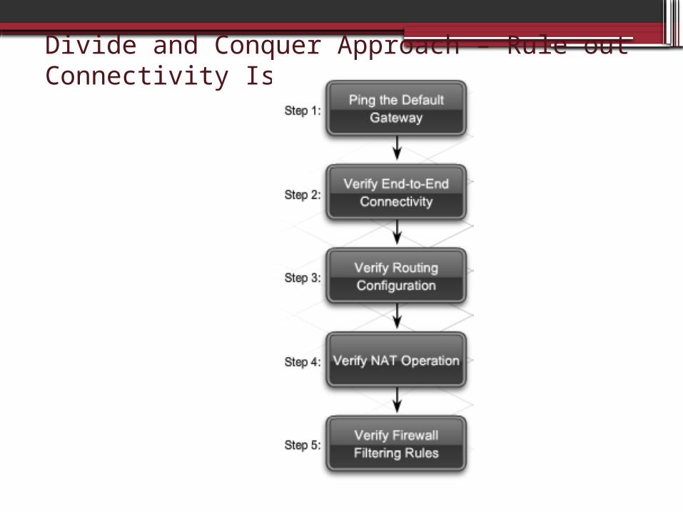
• Use the "divide and conquer" method – start at layer 31. Ping default gateway 2. Verify end to end connectivity – ping
destination3. Verify router configuration4. Verify nat configuration5. Verify firewall filtering
• If connectivity is not the issue, but the end device is still not operating as expected, the problem has been isolated to the upper layers.
Divide and Conquer Approach – Rule out Connectivity Issues

Upper Layer Issues• Upper layer problems prevent services from
being provided to application programs. • A problem at the upper layers can result in
unreachable or unusable resources, even when the lower layers are functional.
• Upper layer issues can exist even with full network connectivity
• Problems with upper layer functions usually affect just a few applications, perhaps even only one
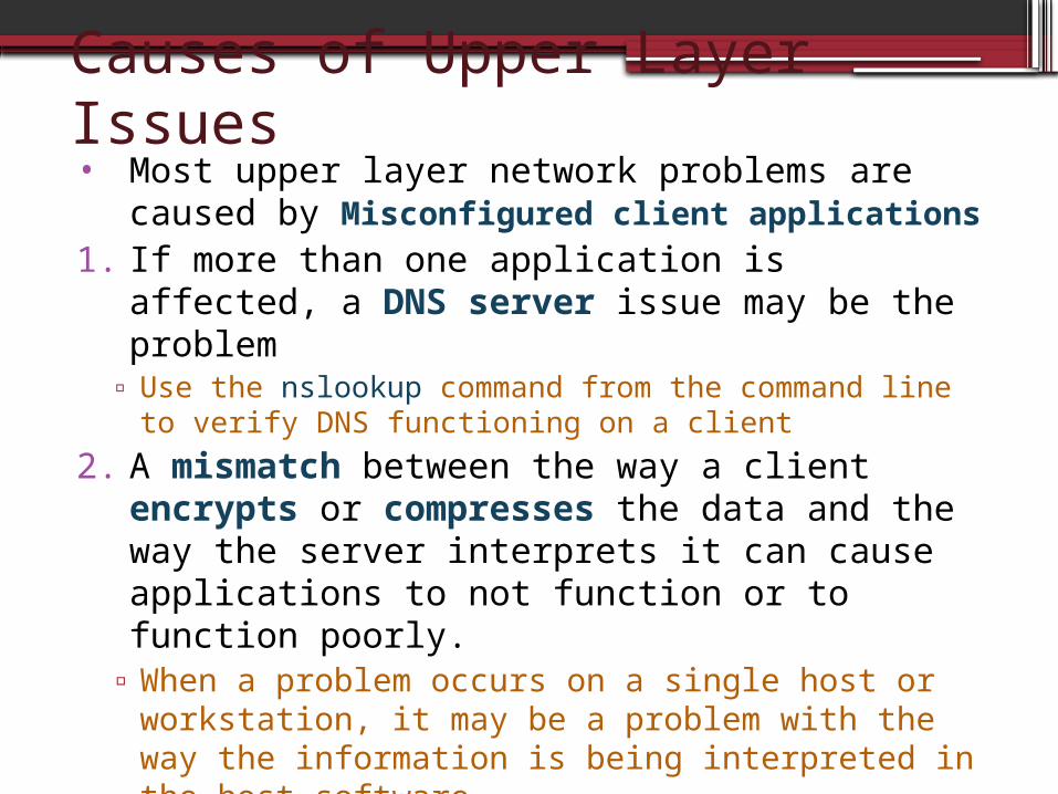
Causes of Upper Layer Issues• Most upper layer network problems are caused
by Misconfigured client applications1. If more than one application is affected, a DNS
server issue may be the problem▫ Use the nslookup command from the command line to
verify DNS functioning on a client
2. A mismatch between the way a client encrypts or compresses the data and the way the server interprets it can cause applications to not function or to function poorly.
▫ When a problem occurs on a single host or workstation, it may be a problem with the way the information is being interpreted in the host software.
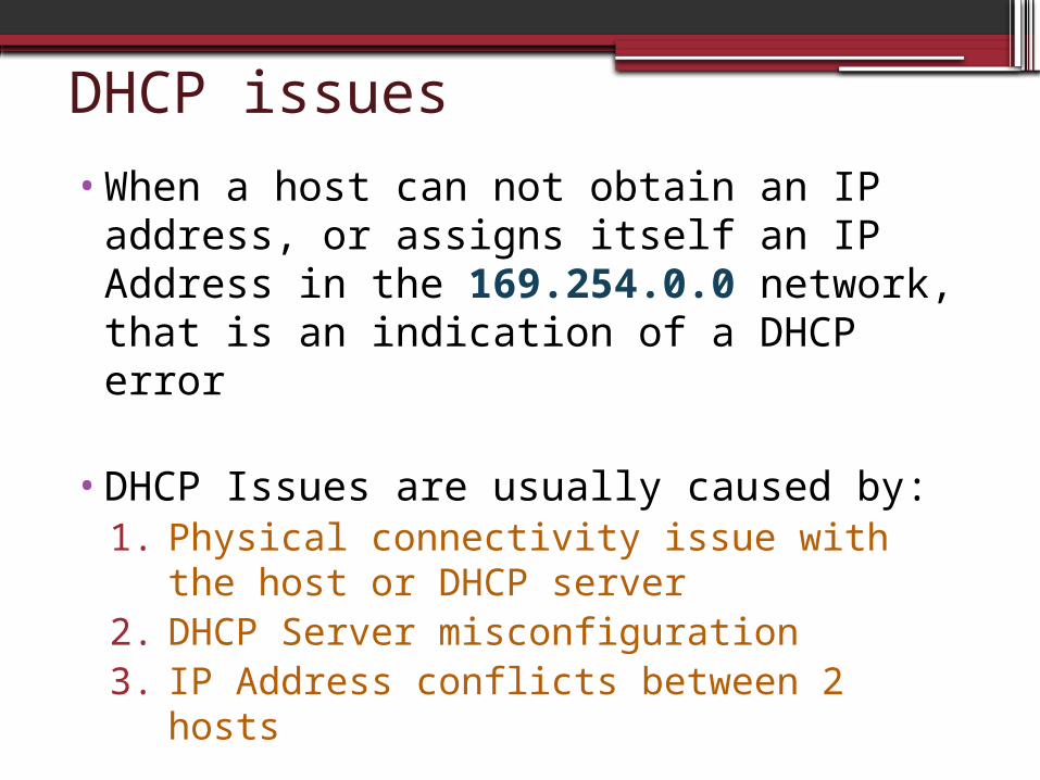
DHCP issues
•When a host can not obtain an IP address, or assigns itself an IP Address in the 169.254.0.0 network, that is an indication of a DHCP error
•DHCP Issues are usually caused by:1. Physical connectivity issue with the host
or DHCP server2. DHCP Server misconfiguration 3. IP Address conflicts between 2 hosts
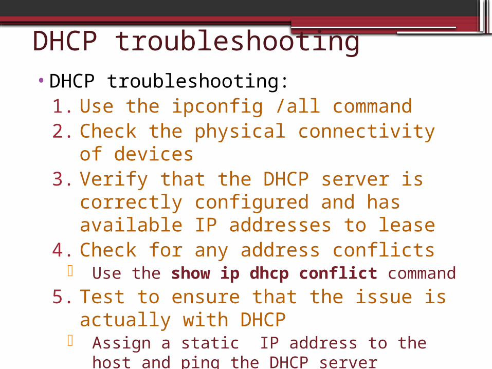
DHCP troubleshooting•DHCP troubleshooting:
1. Use the ipconfig /all command2. Check the physical connectivity of
devices3. Verify that the DHCP server is
correctly configured and has available IP addresses to lease
4. Check for any address conflicts Use the show ip dhcp conflict command
5. Test to ensure that the issue is actually with DHCP
Assign a static IP address to the host and ping the DHCP server

NAT issues• Usually the first indication that there is a NAT problem is
that users cannot reach sites located on the Internet.
•NAT issues:▫Incorrectly designated inside & outside
interfaces The inside interface connects to the local network, which
uses private IP address space The outside interface connects to the public network, usually
the ISP
▫NAT Pool misconfiguration The IP address pool and static NAT translation entries must
use IP addresses that are on the same local IP network as the outside interface
▫No route to the Internet for translated addresses If external users must be able to reach specific servers on the
internal network, be sure that static NAT translations are configured.

NAT Configuration

NAT Troubleshooting1. Verify NAT operation:
▫ Router# show ip nat translations2. Clear NAT translations:
▫ Router# clear ip nat translation *3. Verify that there is a route to the
Internet for the translated addresses▫ Router# traceroute …..

Troubleshooting Tools1. Telnet is an excellent tool to use when
troubleshooting upper layer issues ▫Use Telnet to access networking devices
remotely▫The ability to reach devices using Telnet
indicates that the lower layer connectivity exists between the devices.
▫However, Telnet is an insecure protocol2. SSH is a more secure method for
remote device access.
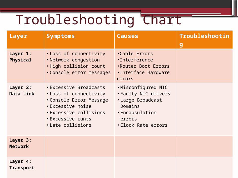
Troubleshooting ChartLayer Symptoms Causes Troubleshootin
gLayer 1: Physical
• Loss of connectivity• Network congestion• High collision count• Console error messages
•Cable Errors•Interference •Router Boot Errors•Interface Hardware errors
Layer 2: Data Link
• Excessive Broadcasts• Loss of connectivity• Console Error Message• Excessive noise • Excessive collisions• Excessive runts• Late collisions
• Misconfigured NIC• Faulty NIC drivers• Large Broadcast
Domains• Encapsulation errors • Clock Rate errors
Layer 3: Network
Layer 4: Transport
Upper Layers
![CCNA Dis1 - Chapter 9 - Troubleshooting Your Network [Compatibility Mode]](https://static.documents.pub/doc/80x56/577d21ff1a28ab4e1e9660b1/ccna-dis1-chapter-9-troubleshooting-your-network-compatibility-mode.jpg)


