Version 9 – 2/9/10 Issued By: _RB____________________ CLP-1 Tauranga City Council Building Inspections Standard Processing Checklist Address: ___________________________________________________ Consent No. ________________ Processor: __________________ Building Category: ________________________ P F N/A Date/Initial B1 Structure Siteworks Council ground conditions OK Site levels to FFL - major cuts not required Cuts @ boundary retained/battered to safe angle Compaction report for fill >600mm Are site barriers required (See NZBC F5) Notes: Retaining Walls: Alternative Solutions Specific designer competent (Record below) Tested to a Verification Method Credible product/system certification Determination Comparison to acceptable solution Expert opinion Other/Notes: Timber Pole/Rail Walls Plans reflect design details Hole size/depth Pole size for relevant height Rail size Drainage Notes:
Transcript
Version 9 – 2/9/10 Issued By: _RB____________________ CLP-1
Tauranga City Council Building Inspections
Standard Processing Checklist Address: ___________________________________________________ Consent No. ________________ Processor: __________________ Building Category: ________________________
P F N/A Date/InitialB1 Structure Siteworks Council ground conditions OK Site levels to FFL - major cuts not required Cuts @ boundary retained/battered to safe angle Compaction report for fill >600mm Are site barriers required (See NZBC F5) Notes: Retaining Walls: Alternative Solutions Specific designer competent (Record below) Tested to a Verification Method Credible product/system certification Determination Comparison to acceptable solution Expert opinion Other/Notes: Timber Pole/Rail Walls Plans reflect design details Hole size/depth Pole size for relevant height Rail size Drainage Notes:
Proprietary Walls Plans reflect design details Ground conditions suitable Notes: 1 of 19 P F N/A Date/InitialFoundations B1/AS1 Identify Standard/s: __________________ B2 AS1 Alternative Solutions Specific designer competent (record below) Tested to a Verification Method Credible product/system certification Determination Comparison to acceptable solution Expert opinion Other Notes: Check PIM/geotech report for ground conditions Peer review provided if Hazardous Agents on site (F1) Ground conditions OK for acceptable solutions (check 3604 3.1.3 if no Geotech)
Elements as per AS or specific design i.e.: Concrete strength Footing dimension Reinforcing size/grade/laps Steel cover Starter size/location Notes:
Blocks/Bondbeam B1/AS1 Identify Standard/s ___________________ B2 Notes: Alternative Solutions Specific designer competent (record below) Tested to a Verification Method Credible product/system certification Determination Comparison to acceptable solution Expert opinion Other/Notes: 2 of 19 P F N/A Date/InitialBuildings to NZS4229 are within limitations in cl. 1.1.3 a - k Specification current Block size specified Starter size corresponds with footing design Steel grades shown Elevation show vert/horizontal steel size/set out Verticals at all corners, wall ends Verticals at each side of >400mm openings Verticals at each side of shrinkage control joints Horizontal steel immediately above and below openings Horizontal steel tied to side verticals Tie (links/stirrups) sizes and location shown Table of specified laps supplied or shown on plan Cover shown on critical faces Control joints location shown on elevations or specified Lintel details/reinforcing clearly shown Details of lintel/vert steel connections Bracing requirements for grouting - walls >2400mm in height (propping)
Tanking drainage for retaining walls clearly shown Tanking membrane specified Protection of tanking membrane shown Notes: Columns (Also for In Situ Walls where applicable) Specification provided Reinforcement size, grade, location Ties size/type/spacing Laps specified Column to beam connection detail Precautions for large pours Concrete strength specified Props as needed Specified design - Engineers drawings or signed architectural plans Notes: Concrete Beams and Beam Control Joints As for columns where applicable Reinforcement size, grade, location Laps specified Beam props specified Specified design - Engineers drawings or signed architectural plans Notes: Precast/Tilt Slab/Other Precast Components Reinforcing size/grade/location Laps specified Lifting/fixing details Fixing details galvanised or stainless for corrosion protection Concrete strength specified Made on or off site - Off site fabricator to be identified and approved Specified design - Engineers drawings or signed architectural plans Notes: 3 of 19 P F N/A Date/InitialSlab B1/AS1 Identify Standard/s ___________________ B2/AS1
Alternative Solutions Specific designer competent (record below) Tested to a Verification Method Credible product/system certification Determination Comparison to acceptable solution Expert opinion Other/Notes: Fill specification Compaction requirements fill >600mm Granular base layer shown DPM specified Slab thickness shown Thickenings shown Cover shown Reinforcing mesh/steel shown Anti cracking measures (slab size/diagonal bars/cuts) Free joints for slabs >24m Concrete strength Keying for waffle slabs FFL as specified in PIM or in relation to bdy levels/road Specified design - Engineers drawings or signed architectural plans Notes: Topping Slabs B1/AS1 Identify Standard/s ___________________ B2/AS1 Notes: Alternative Solutions Specific designer competent (record below) Tested to a Verification Method Credible product/system certification Determination Comparison to acceptable solution Expert opinion Other/Notes: Specified design - Engineers drawings or signed architectural plans Pre Cast Floor panel fabricator competent Additional required steel shown above L/B walls
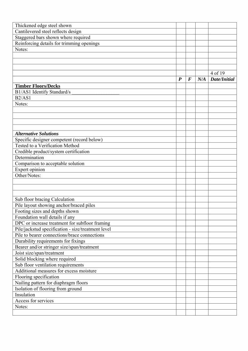
Thickened edge steel shown Cantilevered steel reflects design Staggered bars shown where required Reinforcing details for trimming openings Notes: 4 of 19 P F N/A Date/InitialTimber Floors/Decks B1/AS1 Identify Standard/s ___________________ B2/AS1 Notes: Alternative Solutions Specific designer competent (record below) Tested to a Verification Method Credible product/system certification Determination Comparison to acceptable solution Expert opinion Other/Notes: Sub floor bracing Calculation Pile layout showing anchor/braced piles Footing sizes and depths shown Foundation wall details if any DPC or increase treatment for subfloor framing Pile/jackstud specification - size/treatment level Pile to bearer connections/brace connections Durability requirements for fixings Bearer and/or stringer size/span/treatment Joist size/span/treatment Solid blocking where required Sub floor ventilation requirements Additional measures for excess moisture Flooring specification Nailing pattern for diaphragm floors Isolation of flooring from ground Insulation Access for services Notes:
Wall Framing B1/AS1 Identify Standard/s ___________________ B2/AS1 Notes: Alternative Solutions Specific designer competent (record below) Tested to a Verification Method Credible product/system certification Determination Comparison to acceptable solution Expert opinion Other/Notes: 5 of 19 P F N/A Date/InitialWall Framing Cont... Timber grades specified Timber treatment Steel specification for steel frame Specification for solid timber/composite walls Stud heights/sizes and spacings Top plate requirements (double where bracing lines between 5-6m) Bottom/top plate fixings Diaphrag or Dragon Ties where bracing lines up to 7.5m Bracing schedule and plan Adjustment for stud height or top plate slope Bracing method specification Lintel size and type Lintel uplift fixings Sill/Head trimmers where >3600mm Notes: Roof Framing B1/AS1 Identify Standard/s ___________________ B2/AS1 Notes:
Alternative Solutions Specific designer competent (record below) Tested to a Verification Method Credible product/system certification Determination Comparison to acceptable solution Expert opinion Other/Notes: Timber grades specified Timber treatment framing and valley boards Treatment H3.1 enclosed roof/deck <10° pitch Rafter span and spacing Rafter seating and fixings Purlins size/span/spacing/fixings Bracing Truss design including fixings schedule Minimum pitch for trusses Support for loaded trusses Thickenings in slab for point loads Trimming details for chimneys/sky lights Strenghthening for plant loadings/Solar Panels/AC etc Verandah beams span/treatment Posts treatment/connections Post foundations for uplift Consider flex for large gable ends Notes: All Specifically Designed Structural Elements P/S design received from CP Engineer P/S design review received from CP Engineer Peer review to preferred reviewer required Engineers plans or engineers signed architectural plans Notes: 6 of 19 P F N/A Date/InitialCLADDING Roof Cladding: E2/AS1 Notes: Alternative Solutions Specific designer competent (record below)
Credible product/system certification Determination Comparison to acceptable solution Expert opinion Other/Notes: Pitch OK for specified cladding Specification current Fixing type/size and location Soffits/verges of projecting eaves closed in Compatibility of materials (E2/AS1 Tab 21) Effects of runoff on roof (E2/AS1 Tab 22) Underlay (E2/AS1 Tab 23) Masonry tile type to require underlay (E2/AS1 Tab 10) Underlay support Anti ponding for masonry roof of low pitch Spreaders for higher/lower roofs Upper floor discharges max 25m² Internal valley/hidden gutter support No direct discharge to internal gutters Materials for gutters of <3° slope Internal gutter overflows Catchment areas above penetrations (E2/AS1 Tap 9) Detail for weatherproofing of penetrations Flashings appropriate for wind zone/pitch Notes: Membrane roof/Enclosed Deck - E2 AS1 Sec 8 Roof Min Fall 1:40 (1.5°) Deck minimum fall 1:60 (1°) Max deck area 40m² No steps within deck except to gutter No integral roof gardens No downipe discharge to deck Deck Joist at max 450mm c/c and blocked/nogged at 450mm c/c Ply at least 17mm CD grade, H3.2 treated Ply sheets staggered (brick bond) Sheet edges supported or appraised T & G Ply to be laid C side up and face grain at right angle to joist Detail shows 20mm triangular fillet at upstands Detail shows external edges chamfered to min 5º radius Sheet fixings specified 10g x 50mm s/s at 150 c/c (edge) 200 c/c (centre) Detail shows 3mm gap between sheet edges Notes:
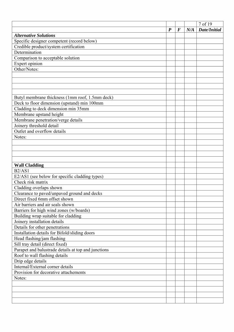
7 of 19 P F N/A Date/InitialAlternative Solutions Specific designer competent (record below) Credible product/system certification Determination Comparison to acceptable solution Expert opinion Other/Notes: Butyl membrane thickness (1mm roof, 1.5mm deck) Deck to floor dimension (upstand) min 100mm Cladding to deck dimension min 35mm Membrane upstand height Membrane penetration/verge details Joinery threshold detail Outlet and overflow details Notes: Wall Cladding B2/AS1 E2/AS1 (see below for specific cladding types) Check risk matrix Cladding overlaps shown Clearance to paved/unpaved ground and decks Direct fixed 6mm offset shown Air barriers and air seals shown Barriers for high wind zones (w/boards) Building wrap suitable for cladding Joinery installation details Details for other penetrations Installation details for Bifold/sliding doors Head flashing/jam flashing Sill tray detail (direct fixed) Parapet and balustrade details at top and junctions Roof to wall flashing details Drip edge details Internal/External corner details Provision for decorative attachements Notes:
Cavity Details Batten size/spacing/treatment Spacers Insulation confinement where studs are >450mm c/c Effective drainage and drying Vermin exclusion provisions Interstorey junctions ≤ 2 storeys Drained interstorey junction > 2 storeys Notes: 8 of 19 P F N/A Date/InitialStucco To E2/AS1 9.3 (All on cavity system) Stud/Nog spacings to NZS 3604 Clause 11 Section through non rigid backing (See NZS 3604 11.8) Rigid backing specified Backing fixing and sheet spacing Reinforcing type specified Fixings and spaces specified Slab/continuous block/concrete foundation Control joints Paint system specified Notes: Timber/Fibre Cement Weatherboards: To E2/AS1 9.4 & 9.5 Timber treatment Vertical w/b direct fixed only (cannot be on cavity) Vertical w/b gaps Vertical w/b batten profile shows weathergroove Section shows laps (varies for profiles) Joint details showing weatherproofing Fixing requirements Protective finish Notes: Profiled Metal Cladding: To E2/AS1 9.6 Horizontal shown on cavity
Vertical as per risk matrix Cladding/flashing durability for exposure conditions Steel/aluminium standard specified Fixings specified Flashing at penetrations/junctions/corners CCA battens isolated from metal cladding Notes: Fibre Cement Sheet Cladding To E2/AS1 9.7 Within scope of E2/AS1 Flush finished sheets 7.5mm minimum Other systems have specified jointing system Fixings specified (E2 Table 2.4) Control joints shown Flashing at joinery and other penetrations Flashings at joints and internal/external corners Fibre Cement Sheet Cladding Cont... Flashings at junctions with other claddings or roof Balustrade/parapet weatherproofing details LRV of paint finish for flush finished monolithic system Notes: 9 of 19 P F N/A Date/InitialPlywood Sheet To E2/AS1 9.8 Within scope of E2/AS1 Min 12mm thick (Fixings E2 Table 2.4) Treatment min H3.1 – with coatings Battens and lapped joint profiles show weathergoove Flashing for joinery/penetrations/corners/junctions All joints shown over supports Durability of cladding Durability of braced elements Fixing of braced elements Coating of braced elements Notes:
EIFS To E2/AS1 9.9 System specification provided Min thickness (40mm) Poly sheet/reinforcing mesh/plaster finish specification Specified head/sill/jamb/corner/base flashings Fixings specified Flashing details for joinery/penetrations/fixing blocks Flashing details for junctions with other claddings R Value where on cavity Decorative moulding requirements/details Notes: Masonry Veneer To E2/AS1 9.2 Specification quotes standards NZS 3604 SNZ HB 4236 Rebate size/width/sealed Venting Plates on foundation wall on nib or continuous flashing Specific design for veneers above 7.5mm (see Alt Solution) Cavity sealed off from roof space and subfloor space Building wrap (insulation confinement) Control joints where required for concrete bricks/blocks Weatherproofing details for joinery/penetrations Steel/Brick Lintels Specified Durability of Steel lintels Drainage for veneer above openings (drainage paths) Veneer to ground clearances specified Secondary cladding (window heads/gables) sealed Notes: 10 of 19 P F N/A Date/InitialOTHER CLADDING SYSTEMS (Alt Solutions) Verify By: Identify Type/System: __________________________ Tested to E2/VM1
DoBH Determination Product certification - to crediable standard Apply the Risk Matrix THEN: Benchmark against E2/AS1 It is comparable to an E2/AS1 system Differences catered for Trained applicator THEN: Check 4 Ds Deflection - Directing water off Drainage - Allowing water out Drying - removal of whats left Durability - surviving intermittent dampness THEN: Check performance History Independent reports Low incidence of failure at WHRS or BRANZ Technical opinion available from credible source Discuss with other staff Notes: Durability – (B2) – Structure All structural elements and difficult to access elements eg: tanking achieve 50 years
Moderately difficult access – elements achieve 15 years Easy access – 5 years Access for Service Notes: Fire – Single Dwellings DEOP < 24m Total Open Path < 60m Check C/AS1 6.3 where foamed plastic specified FRR where within 1m of boundary FRR to eaves projections < 650mm from boundary Check CAS1 7.8.8 to 7.8.10 for carports See C/AS1 1.3.4 where escape heights > 10m F7 Smoke Alarms (Stamp) Notes:
11 of 19 P F N/A Date/InitialFire – All other Buildings Check C/AS1 Fire Report and fire plan provided Fire Designer signed plans if no fire plan Specific design requiring peer review Specific design... copy gone to NZFS DRU Requirements of S112 & S115 Building Act 2004 for alterations or change of use
Occupant load/FHC/FSPs identified Specifications for Fire Safety precautions Open path/DEOP travel distance Protected/Safe path travel distances and widths Number of Final exits required Vertical/Horizontal safe path width Travel distances adjusted for intermediate floors Fire rating intermediate floors Smoke control required for intermediate floors? Final exit widths, direction of opening, hardware Auto door/electronic lock fail safe/alarm override Adequate illumination, normal and in emergency E/lights standard and duration specified – See F6/AS1 Fire/smoke rating for safe/protected paths Safe path ventilation Internal surface finishes Fire Separations Fire stopping for penetrations specified Fire stopping details on approved plans Fire spread via concealed spaces External fire spread Correct fire safety precautions compliance standards specified Smoke control Correct S rating Fire rating of external walls Percentage of openings and distribution OK Structure of fire separations (stability/integrity/insulation) Notes: Access – Single Dwellings Stairs within design limits (D1/AS1 Table 5 & Figure 11)
Complying handrail Vehicle access 1:4 pitch or less Access – All Other Buildings: D1/AS1 & NZS 4121 & Sections 112 & 115 Building Act 2004 Safe approaches and entry to building Stair/ramp dimensions appropriate for use Stairway lighting (see table 8, D1/AS1) Car parking manoeuvring/parking dimensions (AS/NZS 2860) Safety where vehicle routes cross pedestrian routes Slope/crossfall for vehicle/pedestrian routes Access – All other Buildings Cont... Slip resistance of walking surfaces Open raisers protected Handrails Landings for long stairways Notes: 12 of 19 P F N/A Date/InitialAccessible Routes & Facilities: D1/AS1 - NZS 4121 Confirm Required (S112, 115 and 118 Building Act 2004) At least one complying route to, into and within building Identified by signs including international access sign Adequate space Lifts depending on floor numbers/areas/occupancy (Options NZS4121 or D1/AS1)
Appropriate lift dimensions No thresholds/barriers Raised perimeters for wheelchair safety Doors with easily used and located hardware Location of light switches/plugs (See G9/AS1) Stair treads with rounded leading edge Stair dimensions Ramp slope Handrails continuous and both sides Accessible toilet numbers and dimensions Toilet seat height specified Handrails and doors OK Accessible kitchens/laundries/bathrooms/lounges/dining Accessible parking spaces number and dimensions Wheelchair spaces in places of assembly Accessible counters in public buildings Access to performance areas
Hearing enhancement (G5.3.5) Mechanical Access (D2) Specification for Lifts/Escalators/Moving walks Specification quotes relevant standard Specific designs have peer review Reviewer competent Review by preferred reviewer required Auto doors designed to relevant standard (NZS 4239) Specified systems recorded Notes: Surface Water (E1) E1/AS1 Check PIM to ensure: No history of flooding Not adjacent to a watercourse Not low lying Not in secondary flow path Roof gutter size (Figs 15 & 16) Downpipe Size (Table 5) FFL 150mm above crown of road Where below road 150mm from lowest bdy point From drives to kerb etc (Neighbouring Property) Notes: Internal Moisture (E3/AS1) R values achieved in habitable areas (P/S to confirm on installation?) Water splash/accidental spillage in wet areas Sealing substrates in wet areas Check wet area membrane substrate against membrane roof/enclosed deck section
Membrane fit for purpose Notes: 13 of 19 P F N/A Date/InitialAlternative Solutions Specific designer competent (record below) Credible product/system certification Determination Comparison to acceptable solution Expert opinion Other/Notes:
Hazardous Building Material (F2/AS1) Glazing standard specified (Identify_______________ ) Glazing schedule OK (Safety Glass nominated) Asbestos materials bonded/encapsulated Notes: Hazardous Substances (F3) Design reviewed by HazSub certifer Network utility services protected Notes: Safety From Falling (F4) Barriers Common area heights Retaining walls fall >1.0m Swimming Pools Restrictors Notes: Construction/Demolition Hazards (F5) Barrier construction details provided Barrier suitable for height/distance boundary Notes: Personal Hygiene (G1/AS1) Adequate toilets provided Space of toilet area Notes: Laundering (G2/AS1) Adequate provisions for laundering (Table 1) Adequate space for laundry Notes: Food Preparation (G3) Residential - Cooking/Washing/Surfaces/Food Preparation Specific design for commercial kitchen Specific design for food processing areas Vermin exclusion provisions Peer review supplied Reviewer competent
Review from preferred reviewer required Hospital/mortuary/slaughter houses has specific design (G3.3.6) Notes: 14 of 19 P F N/A Date/InitialVentilation (G4) Mechanical ventilation flow rates specified. Ducting to outside air Inlet ducts location in relations to drain vents Extract ducts avoid nuisance to neighbour/s Fire stopping at fire separations Impact on STC/IIC Specific design peer reviewed Review by preferred reviewer required Specified systems recorded Natural Ventilation - Openings 5% of floor area Notes: Interior Environment (G5/AS1) Adequate heating/space for child care/old persons Notes: Airbourne/Impact Sound (G6) Plans endorsed with field test requirement STC/IIC between occupancies Provisions for diagonal sound restriction (eg IIC from Decks) Notes: Natural Light/Outside Awareness (G7/AS1) Habitable spaces have natural light Awareness of outside in habitable spaces Notes: Artificial Light (G8/AS1) Adequate watts (see Table 1) Check lighting plan against Table in G8/AS1 Consider H1.3.5(Commercial/assembly buildings only) Notes: Electricity (G9), Piped Services (G10), Gas (G11) Specifications as per Acceptable Solutions P/S from endorsed requiring Energy Works Cert Adequate ventilation – See G4/AS1 2.0 (Gas Appliance) Notes: Water Supplies G12/AS1 Water supply system specified (Table 1 G12/AS1)
Equipotenial bonding (metal pipes) (see G12/AS1) Provisions for indentification on non potable water Potable water supplied Protection of potable supply adequate (BFP/Airgaps) Plans show location and type of back flow preventor Water tanks to ensure supply – G12/AS1 5.0 (Community Care) Isolation at each unit in MU Dwellings HW spec quotes G12/AS1 for valves/pipe sizes or GAS Solar Heating Minimum 50 litre Storage per m² of Collector Area Solar Panel & HWC Position Panel Fixing Detail Tempering Valve & Seismic Straps on HWC Specified Relief Valve & Exp Valve or Open Vent Specified Controller and Pump etc Specified G12-AS2 Stated for Install Smoke Detectors Notes: 15 of 19 P F N/A Date/InitialFoul Water (G13) Sanitary Plumbing/Drainage system specified G13/AS1 AS/NZS 3500.2.2 (See G13/AS1 Clause 8) Wastes/drain diameter/gradient adequate for discharge units FWGs charged and in same compartment Access for maintenance/clearing blockages Adequate venting Vent location in relation to opening in building Impact of drains/wastes on other building elements Structural support & overflow for water tanks in roof spaces Septic tank design & effluent discharge Provision for accidential flooding in Multi-Unit Dwellings Notes: Drainage G13/AS2 AS 3500.2.2 BS 2032 Drainage standard specified Falls shown (1:60 AS3500 1:120 G13/AS2) Layout simple with least changes of direction possible Inspection bends, rodding eye and junctions shown
Drain straight between bends junctions Provision for poor ground conditions Relief gully provided Venting main drain and branch drains Building foundations not compromised Water test specified - endorsed PIM requirements for s/water Specified system (e.g. pump alarms) recorded for Compliance Schedule Drain diameter gradient adequate for discharge units Industrial Liquid Waste (G14) Applicant has identified possible contaminations Check with applicant in industrial use Check table 1 G14/VM1 Refer to TCC Trade Waste division Hazardous Substances to be certified by HasSub certifier Security provisions for treatment facility Recheck protection measures for portable water Notes: Solid Waste (G15) Water supply and drainage available Confirm capacity of vessels/storage area Carry distance to area/chute Storage areas to G15/AS1 Chutes and side entry hoppers to G15/AS1 Ventilation Fire separation of storage area and chutes Notes: 16 of 19 P F N/A Date/InitialEnergy Efficiency (H1) – Housing & <300m² Schedule method <30% total glazing Schedule method <30% total glazing on W/E/S walls Calculation method <50% total glazing Other (>50% total glazing) to achieve BPI <1.55 Notes: Energy Efficiency (H1) Large Buildings >300m² Thermal Envelope (NZS 4243.1) Scheduled method <50% total glazing
Calculation method <50% total glazing Calculation method >50% total glazing Other: Modelling method BESTEST Modelling method DBH Approved (Record) Notes: Lighting (NZS4243.2) CB or CNR Buildings Only Schedule method Calculation method PS1 supplied and author verified (Record) PS4 requested at final Notes: Specified Compliance Schedule Systems Complete TCC Schedule of Information for Compliance Schedule Details and attach to this checklist (check standards quoted are correct) Completed: Yes / No Not Completed – record reason here: Notes: Pools Fencing/Barriers BFP Backwash Discharge Pool Structure Ground Check Requried? Alt/Solution NZS 8500/2006 Notes: Solid Fuel Heaters Inbuilt Protection of Combustibles by barrier or isolation Manufacturers Specs Supplied Isolation to Specs Seismic restraint Flashings roof/wall penetrations Floor plan shows location Flue clear of obstructions/existing building elements Notes: 17 of 19
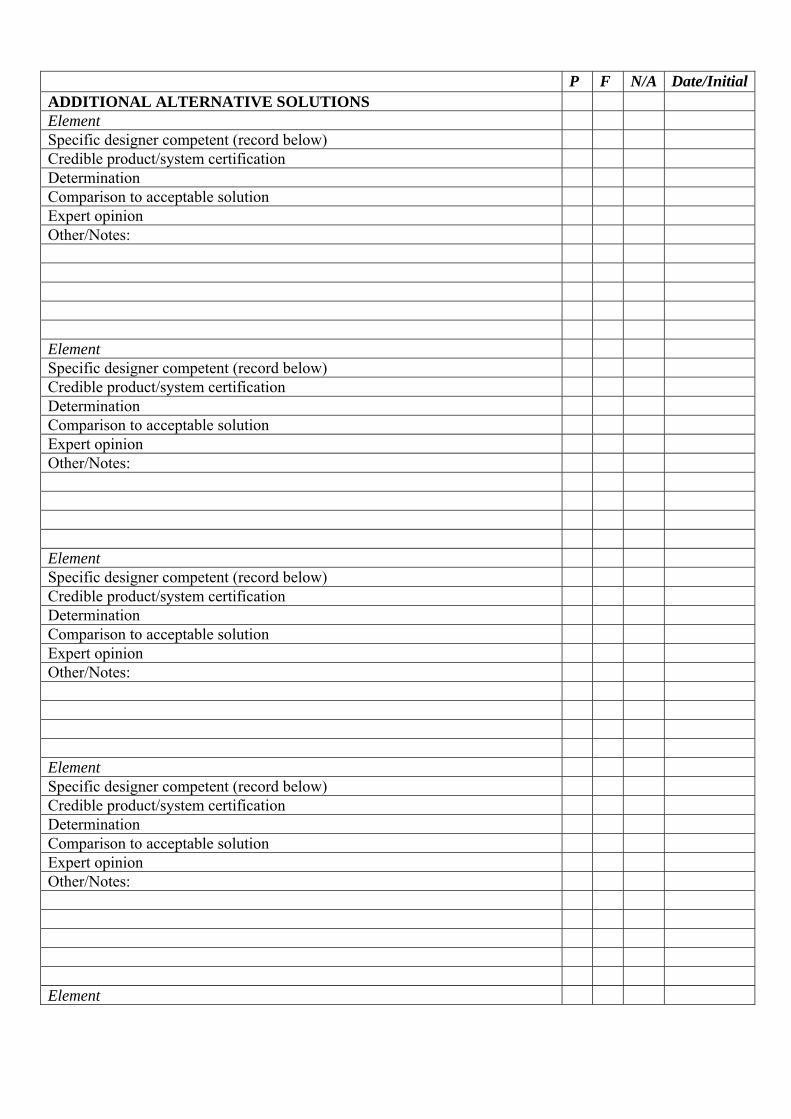
P F N/A Date/InitialADDITIONAL ALTERNATIVE SOLUTIONS Element Specific designer competent (record below) Credible product/system certification Determination Comparison to acceptable solution Expert opinion Other/Notes: Element Specific designer competent (record below) Credible product/system certification Determination Comparison to acceptable solution Expert opinion Other/Notes: Element Specific designer competent (record below) Credible product/system certification Determination Comparison to acceptable solution Expert opinion Other/Notes: Element Specific designer competent (record below) Credible product/system certification Determination Comparison to acceptable solution Expert opinion Other/Notes: Element
Specific designer competent (record below) Credible product/system certification Determination Comparison to acceptable solution Expert opinion Other/Notes: 18 of 19 GENERAL NOTES
I am satisfied on reasonable grounds that the provisions of the Building Code will be met if the building work in relation to the attached application is properly completed in accordance with the attached plans and specifications Signed: ______________________________ Date: _____________________ 19 of 19


![Olivio Grande - Candelabra Pole Top [OLG] selux Grande - Candelabra Pole Top Refer to individual pole specification sheets for construction details, ... Olivio Grande - Candelabra](https://static.documents.pub/doc/80x56/5adea1547f8b9ad66b8bc8b5/olivio-grande-candelabra-pole-top-olg-grande-candelabra-pole-top-refer-to.jpg)


