Product Manual 35072V2 (Revision -, 4/2018) Original Instructions Vertex Compressor Control For Performance and Compressor Control Volume 2 Application Examples and Service Menu Manual 35072 consists of 3 volumes (35072V1, 35072V2, & 35072V3) Released
Transcript
Product Manual 35072V2(Revision -, 4/2018)
Original Instructions
Vertex Compressor Control For Performance and Compressor Control
Volume 2 Application Examples and Service Menu
Manual 35072 consists of 3 volumes (35072V1, 35072V2, & 35072V3)
Released
General Precautions
Read this entire manual and all other publications pertaining to the work to be performed before installing, operating, or servicing this equipment.
Practice all plant and safety instructions and precautions.
Failure to follow instructions can cause personal injury and/or property damage.
Revisions
This publication may have been revised or updated since this copy was produced. To verify that you have the latest revision, check manual 26455, Customer Publication Cross Reference and Revision Status & Distribution Restrictions, on the publications page of the Woodward website:
www.woodward.com/publications The latest version of most publications is available on the publications page. If your publication is not there, please contact your customer service representative to get the latest copy.
Proper Use
Any unauthorized modifications to or use of this equipment outside its specified mechanical, electrical, or other operating limits may cause personal injury and/or property damage, including damage to the equipment. Any such unauthorized modifications: (i) constitute "misuse" and/or "negligence" within the meaning of the product warranty thereby excluding warranty coverage for any resulting damage, and (ii) invalidate product certifications or listings.
Translated Publications
If the cover of this publication states "Translation of the Original Instructions" please note:
The original source of this publication may have been updated since this translation was made. Be sure to check manual 26455, Customer Publication Cross Reference and Revision Status & Distribution Restrictions, to verify whether this translation is up to date. Out-of-date translations are marked with . Always compare with the original for technical specifications and for proper and safe installation and operation procedures.
Revisions— A bold, black line alongside the text identifies changes in this publication since the
last revision. Woodward reserves the right to update any portion of this publication at any time. Information provided by Woodward is believed to be correct and reliable. However, no responsibility is assumed by Woodward unless otherwise expressly undertaken.
CHAPTER 12. APPLICATION NOTES ............................................................................................... 10 Overview ..................................................................................................................................................... 10 Example Applications .................................................................................................................................. 10 Example 1– Single Anti-surge Loop ............................................................................................................ 11 Example 2– Single Anti-Surge Loop with Performance Control on Compressor Suction Pressure via IGV Positioning ................................................................................................................................................... 20 Example 3– Single Anti-Surge Loop With Performance Control on Compressor Discharge Pressure via Discharge Throttle Valve Positioning and Load Sharing with Control on the Common Discharge Header Pressure ...................................................................................................................................................... 27 Example 4– Two Anti-Surge Loops ............................................................................................................ 32 Example 5– Two Anti-Surge Loops with Performance Control On Compressor Discharge Pressure via Speed Control Setpoint ............................................................................................................................... 33 Example 6– Two Anti-Surge Loops with Performance Control On Compressor Suction Pressure via Suction Throttle Valve And Load Sharing With Control On The Common Discharge Header Pressure .... 34
CHAPTER 13. OPERATOR INTERFACE ............................................................................................ 35 Introduction ................................................................................................................................................. 35 Graphical Display and Key Inputs ............................................................................................................... 35 Service Panel Modes and User Levels ....................................................................................................... 36
CHAPTER 14. SERVICE MENU PROCEDURES ................................................................................. 38 Overview ..................................................................................................................................................... 38 Using the Service Menus ............................................................................................................................ 39
APPENDIX B. VERTEX SERVICE MODE WORKSHEET ...................................................................... 81
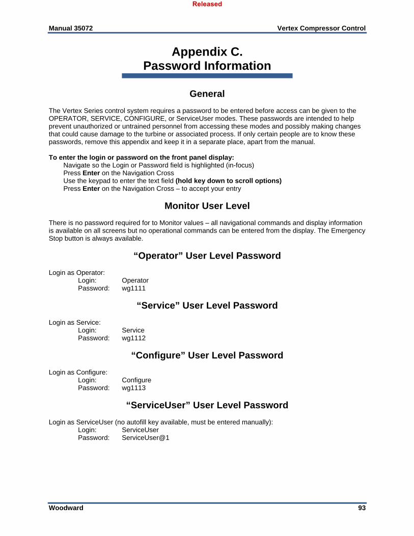
APPENDIX C. PASSWORD INFORMATION ........................................................................................ 93 General ........................................................................................................................................................ 93
Released
Manual 35072 Vertex Compressor Control
Woodward 2
Monitor User Level ...................................................................................................................................... 93 “Operator” User Level Password ................................................................................................................ 93 “Service” User Level Password ................................................................................................................... 93 “Configure” User Level Password ............................................................................................................... 93 “ServiceUser” User Level Password ........................................................................................................... 93
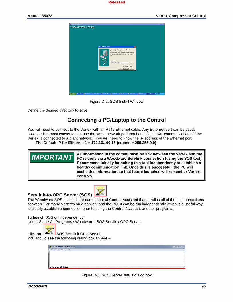
APPENDIX D. SERVLINK-TO OPC SERVER (SOS) TOOL................................................................. 94 SOS Communication Link ........................................................................................................................... 94 Installing SOS ............................................................................................................................................. 94 Connecting a PC/Laptop to the Control ...................................................................................................... 95
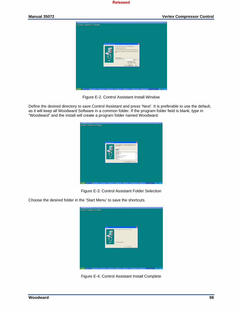
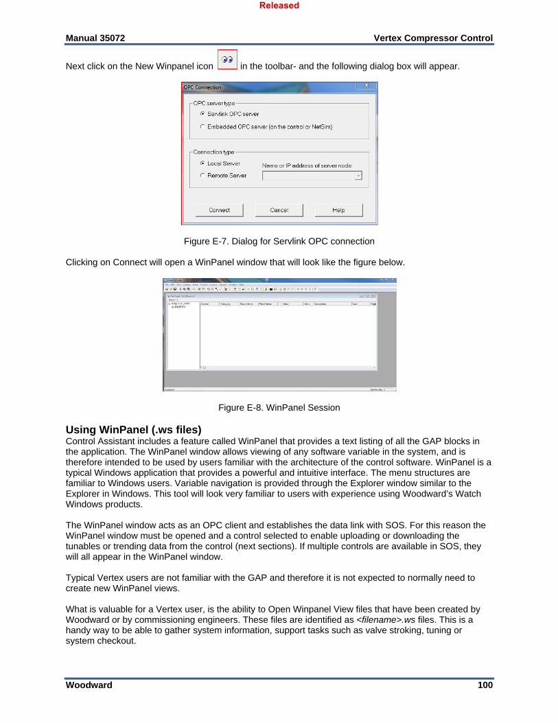
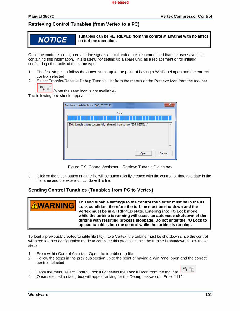
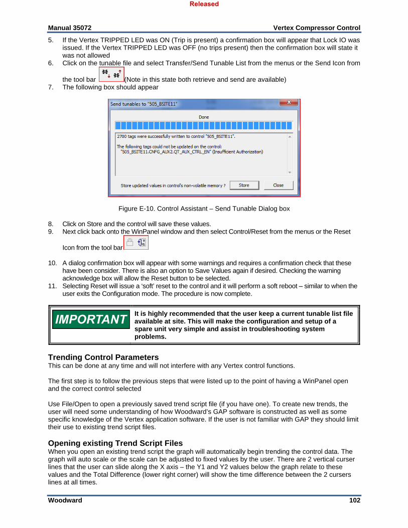
APPENDIX E. CONTROL ASSISTANT—SOFTWARE INTERFACE TOOL .............................................. 97 Features of Control Assistant ...................................................................................................................... 97 Installing Control Assistant .......................................................................................................................... 97 Using Control Assistant ............................................................................................................................... 99
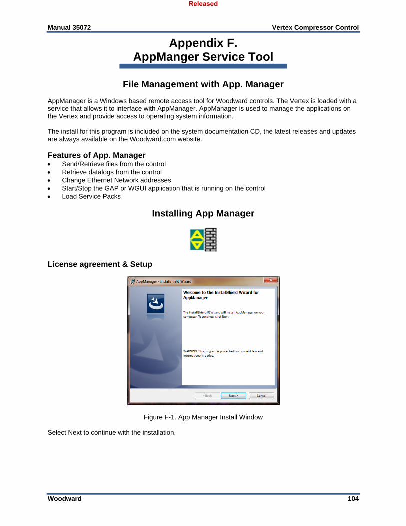
APPENDIX F. APPMANGER SERVICE TOOL .................................................................................. 104 File Management with App. Manager ....................................................................................................... 104 Installing App Manager ............................................................................................................................. 104
APPENDIX G. CONFIGURING NETWORK TCP/IP ADDRESSES ....................................................... 111
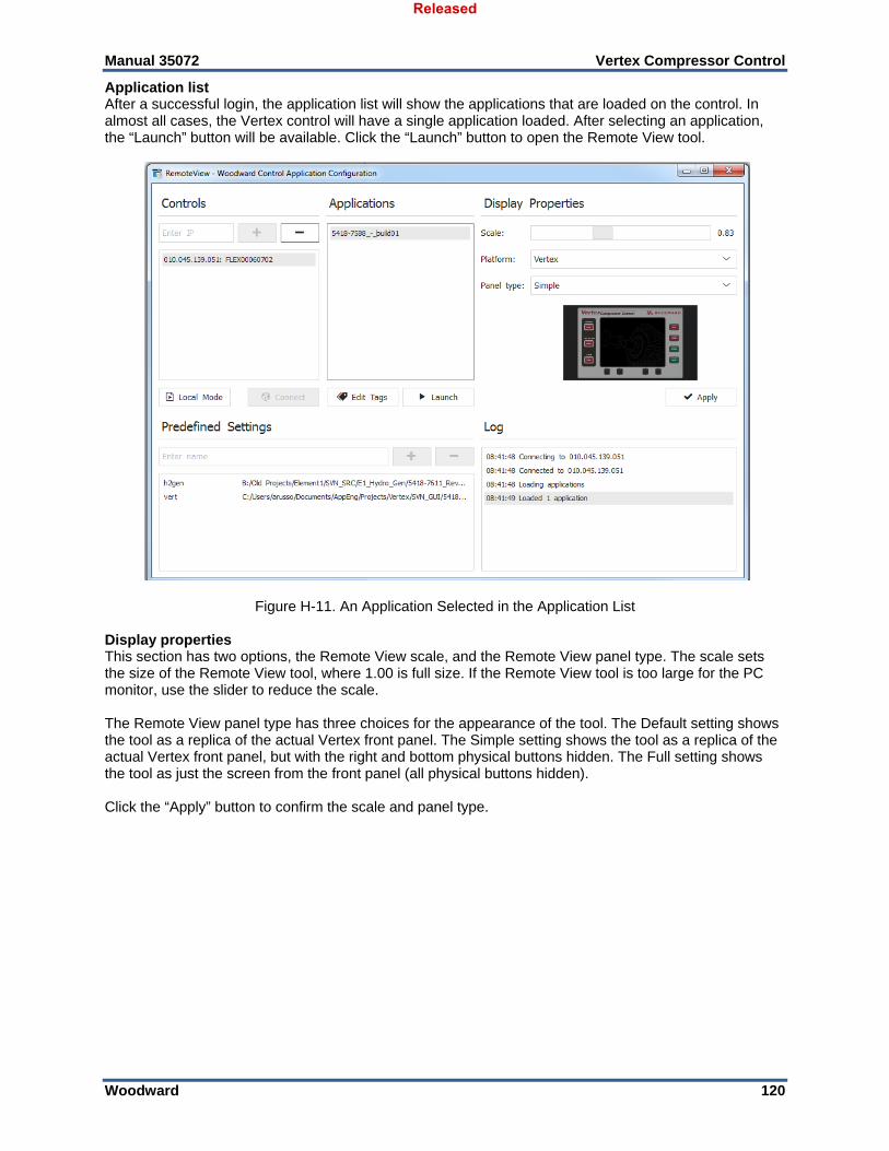
APPENDIX H. REMOTEVIEW TOOL ............................................................................................... 113
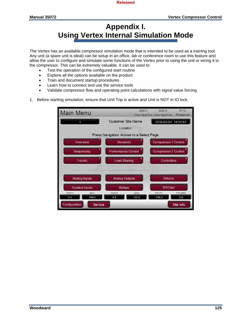
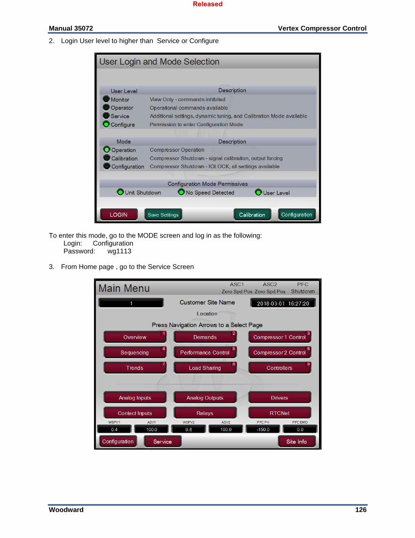
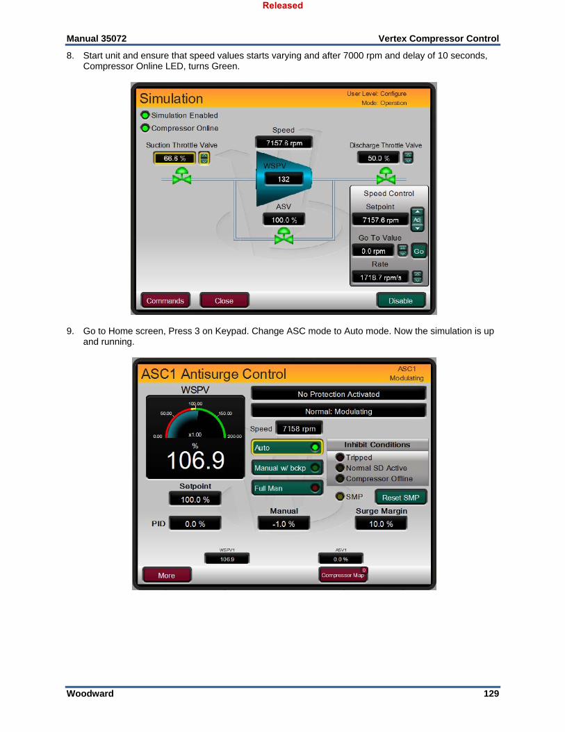
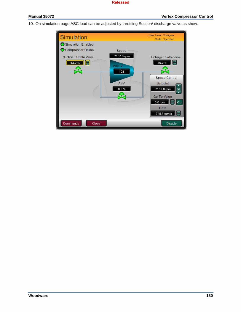
APPENDIX I. USING VERTEX INTERNAL SIMULATION MODE .......................................................... 125
APPENDIX J. CUSTOM TAG NAME PROCEDURE ........................................................................... 131
REVISION HISTORY ..................................................................................................................... 132
The following are trademarks of Woodward, Inc.: ProTech Woodward The following are trademarks of their respective companies: Modbus (Schneider Automation Inc.) Pentium (Intel Corporation)
Released
Manual 35072 Vertex Compressor Control
Woodward 3
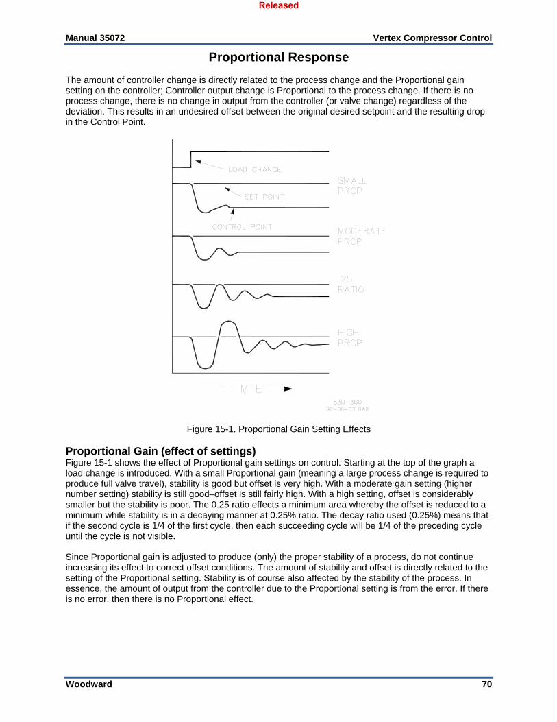
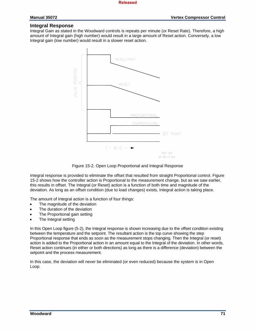
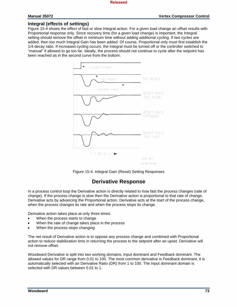
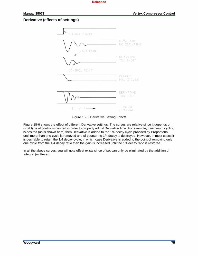
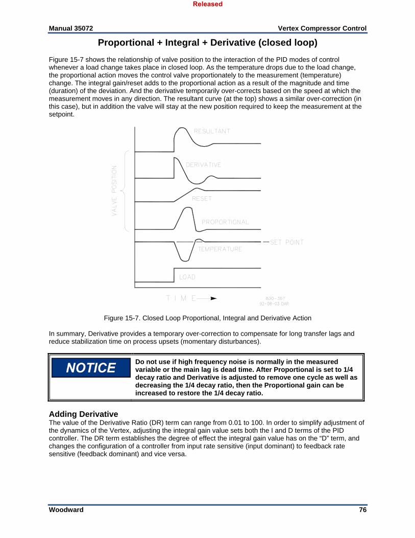
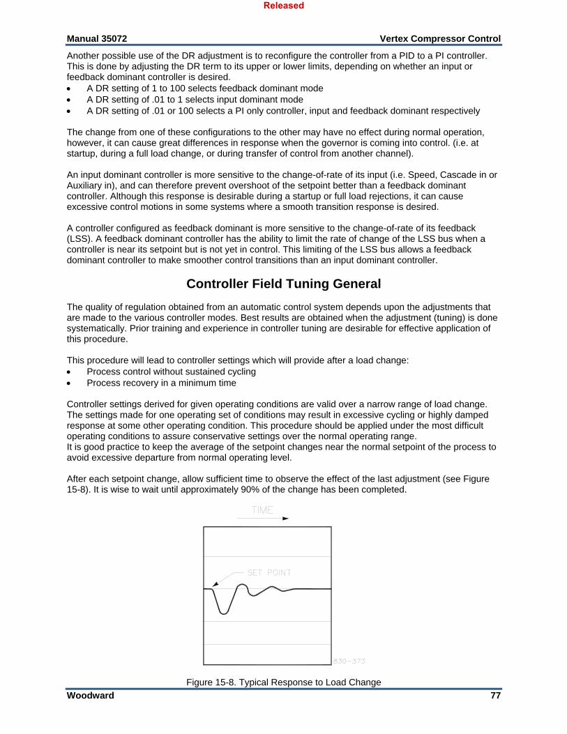
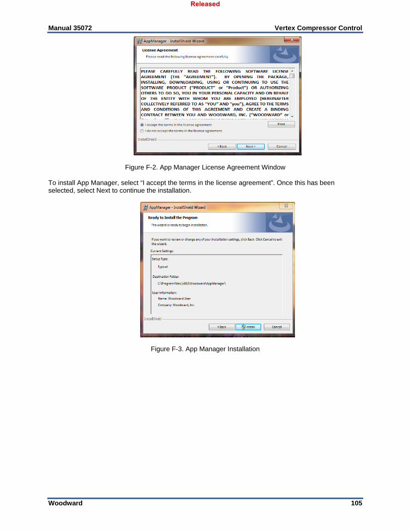
Illustrations and Tables Figure 12-1. Single Anti-surge Loop ........................................................................................................... 11 Figure 12-3. Train Configuration Page 1 Example ..................................................................................... 13 Figure 12-4. Compressor Layout Example ................................................................................................. 14 Figure 12-5. Antisurge Control > Online Detection Example ...................................................................... 15 Figure 12-6. Antisurge Control Tripped ....................................................................................................... 16 Figure 12-7. Compressor Map .................................................................................................................... 17 Figure 12-8. Initiate Normal Stop ................................................................................................................ 18 Figure 12-9. Abort Normal Stop .................................................................................................................. 19 Figure 12-10. Compressor Example 2 Overview ........................................................................................ 20 Figure 12-11. Performance Configuration Page 1 ...................................................................................... 21 Figure 12-12. Performance Configuration Page 2 ...................................................................................... 22 Figure 12-13. Performance Configuration Page 2 ...................................................................................... 23 Figure 12-14. Performance Limiter 1 Configuration .................................................................................... 24 Figure 12-15. Train Commands Contact Input Configuration ..................................................................... 25 Figure 12-16. Compressor Example 3 Overview ........................................................................................ 27 Figure 12-17. Performance Control Example 3 .......................................................................................... 29 Figure 12-18. Load Sharing Configuration Example ................................................................................... 30 Figure 12-19. Load Sharing Configuration AI Example .............................................................................. 30 Figure 12-20. Compressor Example 4 Overview ........................................................................................ 32 Figure 12-21. Compressor Example 5 Overview ........................................................................................ 33 Figure 12-22. Compressor Example 6 Overview ........................................................................................ 34 Figure 13-1 Vertex Keypad and Display ..................................................................................................... 35 Figure 14-1. User Login for Service ............................................................................................................ 38 Figure 14-2. Authorized and Unauthorized Components ........................................................................... 39 Figure 14-3 Service Menu ........................................................................................................................... 40 Figure 15-1. Proportional Gain Setting Effects ........................................................................................... 70 Figure 15-2. Open Loop Proportional and Integral Response .................................................................... 71 Figure 15-3. Closed Loop Proportional and Integral Response .................................................................. 72 Figure 15-4. Integral Gain (Reset) Setting Responses ............................................................................... 73 Figure 15-5. Closed Loop Proportional and Derivative Action .................................................................... 74 Figure 15-6. Derivative Setting Effects ....................................................................................................... 75 Figure 15-7. Closed Loop Proportional, Integral and Derivative Action ...................................................... 76 Figure 15-8. Typical Response to Load Change ........................................................................................ 77 Figure D-1. SOS .......................................................................................................................................... 94 Figure D-2. SOS Install Window ................................................................................................................. 95 Figure D-3. SOS Server status dialog box .................................................................................................. 95 Figure D-4. SOS – New Session box .......................................................................................................... 96 Figure D-5. SOS - Enter Vertex TCP/IP address ........................................................................................ 96 Figure D-6. SOS – Active Links dialog box ................................................................................................. 96 Figure E-1. Control Assistant License Agreement ...................................................................................... 97 Figure E-2. Control Assistant Install Window .............................................................................................. 98 Figure E-3. Control Assistant Folder Selection ........................................................................................... 98 Figure E-4. Control Assistant Install Complete ........................................................................................... 98 Figure E-5. Install Restart Window ............................................................................................................. 99 Figure E-6. Control Assistant Window ........................................................................................................ 99 Figure E-7. Dialog for Servlink OPC connection ....................................................................................... 100 Figure E-8. WinPanel Session .................................................................................................................. 100 Figure E-9. Control Assistant – Retrieve Tunable Dialog box .................................................................. 101 Figure E-10. Control Assistant – Send Tunable Dialog box ..................................................................... 102 Figure E-11. Control Assistant – Speed Control Trend Script .................................................................. 103 Figure E-12. Control Assistant – Create Trend Script File ........................................................................ 103 Figure F-1. App Manager Install Window .................................................................................................. 104 Figure F-2. App Manager License Agreement Window ............................................................................ 105 Figure F-3. App Manager Installation ........................................................................................................ 105 Figure F-4. App Manager Install Complete ............................................................................................... 106 Figure F-5. AppManager Window ............................................................................................................. 106
Released
Manual 35072 Vertex Compressor Control
Woodward 4
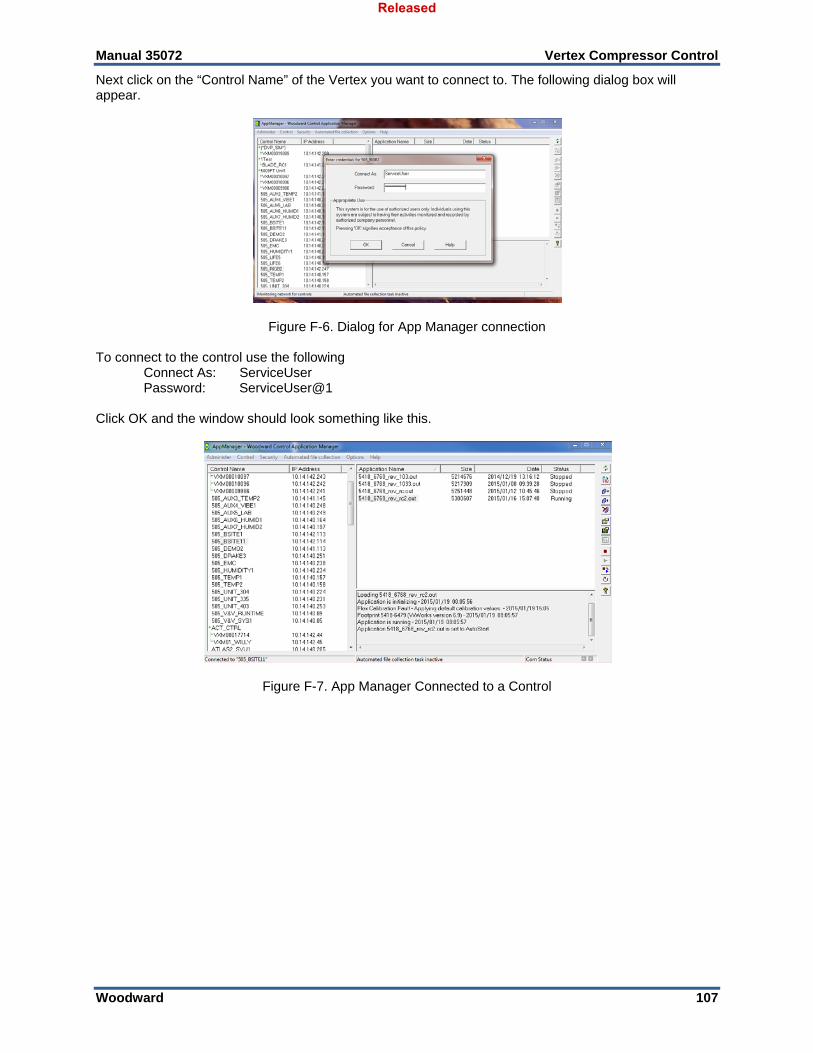
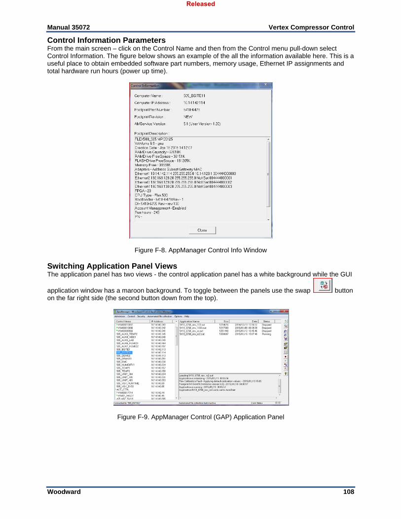
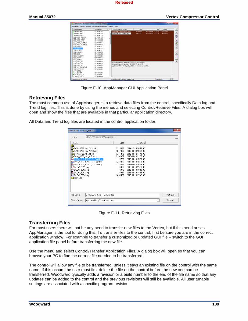
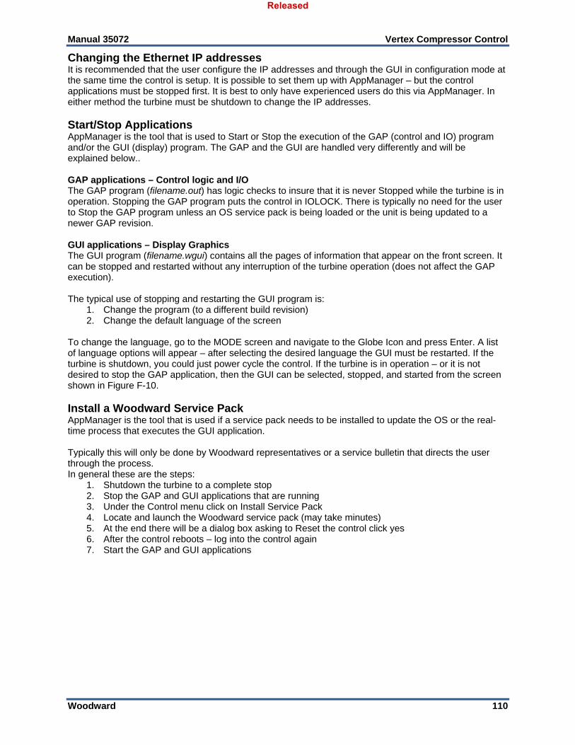
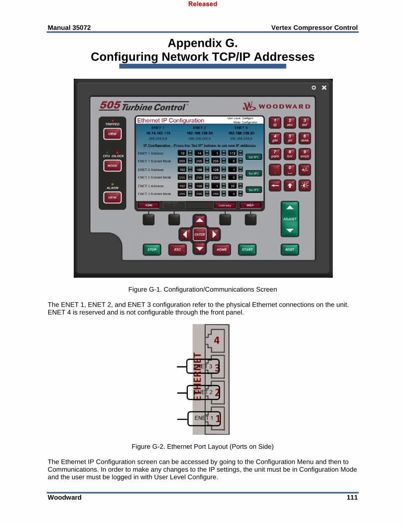
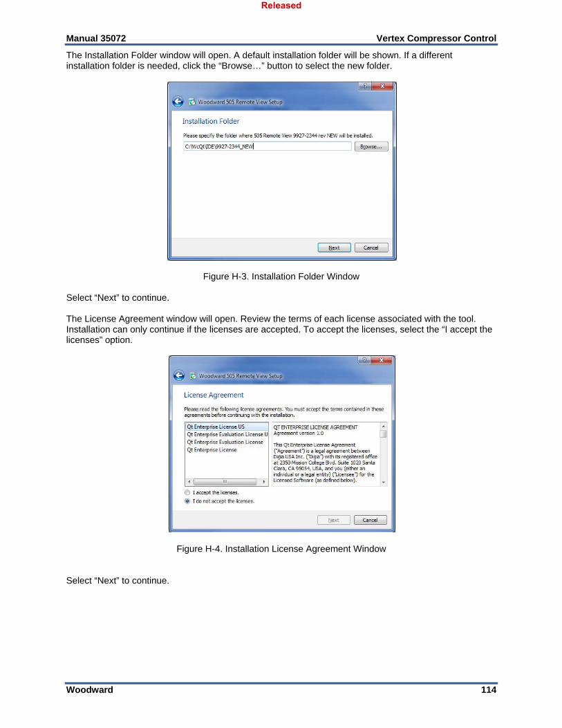
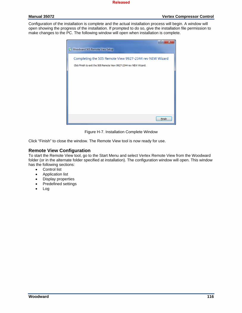
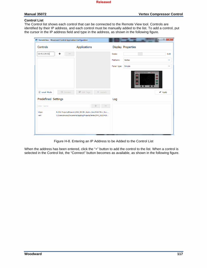
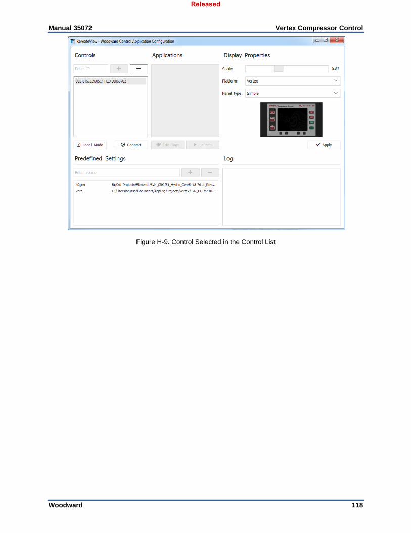
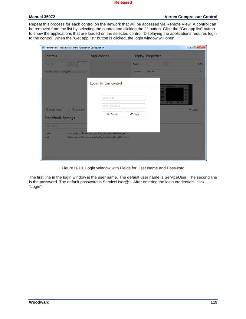
Figure F-6. Dialog for App Manager connection ....................................................................................... 107 Figure F-7. App Manager Connected to a Control .................................................................................... 107 Figure F-8. AppManager Control Info Window ......................................................................................... 108 Figure F-9. AppManager Control (GAP) Application Panel ...................................................................... 108 Figure F-10. AppManager GUI Application Panel .................................................................................... 109 Figure F-11. Retrieving Files ..................................................................................................................... 109 Figure G-1. Configuration/Communications Screen ................................................................................. 111 Figure G-2. Ethernet Port Layout (Ports on Side) ..................................................................................... 111 Figure H-1. Window Shown when the Time Limit is Exceeded ................................................................ 113 Figure H-2. Installation Welcome Window ................................................................................................ 113 Figure H-3. Installation Folder Window ..................................................................................................... 114 Figure H-4. Installation License Agreement Window ................................................................................ 114 Figure H-5. Installation Start Menu Shortcuts Window ............................................................................. 115 Figure H-6. Installation Ready to Install Window ...................................................................................... 115 Figure H-7. Installation Complete Window ................................................................................................ 116 Figure H-8. Entering an IP Address to be Added to the Control List ........................................................ 117 Figure H-9. Control Selected in the Control List ....................................................................................... 118 Figure H-10. Login Window with Fields for User Name and Password .................................................... 119 Figure H-11. An Application Selected in the Application List .................................................................... 120 Figure H-12. Default View of the Tool ....................................................................................................... 121 Figure H-13. Simple View of the Tool ....................................................................................................... 121 Figure H-14. Full View of the Tool ............................................................................................................ 122 Figure H-15. Entering a Name for the Current Settings ............................................................................ 122 Figure H-16. A New Settings File Entered in the Predefined Settings List ............................................... 123 Figure H-17. Remote View Tool (Default Setting) after Opening from the Configuration Window ........... 124 Table 12-1. Example Application Summary ................................................................................................ 11 Table 13-1 Mode Access by User Level ..................................................................................................... 36 Table 14-1. Service Mode Parameters ....................................................................................................... 41 Table A-1. Software Specifications ............................................................................................................. 80
Released
Manual 35072 Vertex Compressor Control
Woodward 5
Warnings and Notices Important Definitions
This is the safety alert symbol used to alert you to potential personal injury hazards. Obey all safety messages that follow this symbol to avoid possible injury or death.
DANGER - Indicates a hazardous situation, which if not avoided, will result in death or serious injury. WARNING - Indicates a hazardous situation, which if not avoided, could result in death or serious
injury. CAUTION - Indicates a hazardous situation, which if not avoided, could result in minor or moderate
injury. NOTICE - Indicates a hazard that could result in property damage only (including damage to the
control). IMPORTANT - Designates an operating tip or maintenance suggestion.
Overspeed /
Overtemperature / Overpressure
The engine, turbine, or other type of prime mover should be equipped with an overspeed shutdown device to protect against runaway or damage to the prime mover with possible personal injury, loss of life, or property damage.
The overspeed shutdown device must be independent of the prime mover control system. An overtemperature or overpressure shutdown device may also be needed for safety, as appropriate.
Personal Protective Equipment
The products described in this publication may present risks that could lead to personal injury, loss of life, or property damage. Always wear the appropriate personal protective equipment (PPE) for the job at hand. Equipment that should be considered includes but is not limited to: Eye Protection Hearing Protection Hard Hat Gloves Safety Boots Respirator
Always read the proper Material Safety Data Sheet (MSDS) for any working fluid(s) and comply with recommended safety equipment.
Start-up
Be prepared to make an emergency shutdown when starting the engine, turbine, or other type of prime mover, to protect against runaway or overspeed with possible personal injury, loss of life, or property damage.
Battery Charging
Device
To prevent damage to a control system that uses an alternator or battery-charging device, make sure to turn off the charging device before disconnecting the battery from the system.
Released
Manual 35072 Vertex Compressor Control
Woodward 6
Electrostatic Discharge Awareness
Electrostatic Precautions
Electronic controls contain static-sensitive parts. Observe the following precautions to prevent damage to these parts: Discharge body static before handling the control (with power to
the control turned off, contact a grounded surface and maintain contact while handling the control).
Avoid all plastic, vinyl, and Styrofoam (except antistatic versions) around printed circuit boards.
Do not touch the components or conductors on a printed circuit board with your hands or with conductive devices.
To prevent damage to electronic components caused by improper handling, read and observe the precautions in Woodward manual 82715, Guide for Handling and Protection of Electronic Controls, Printed Circuit Boards, and Modules.
Follow these precautions when working with or near the control. 1. Avoid the build-up of static electricity on your body by not wearing clothing made of synthetic
materials. Wear cotton or cotton-blend materials as much as possible because these do not store static electric charges as much as synthetics.
2. Do not remove the printed circuit board (PCB) from the control cabinet unless absolutely necessary. If you must remove the PCB from the control cabinet, follow these precautions:
Do not touch any part of the PCB except the edges. Do not touch the electrical conductors, the connectors, or the components with conductive
devices or with your hands. When replacing a PCB, keep the new PCB in the plastic antistatic protective bag it comes in
until you are ready to install it. Immediately after removing the old PCB from the control cabinet, place it in the antistatic protective bag.
To prevent damage to electronic components caused by improper handling, read and observe the precautions in Woodward manual 82715, Guide for Handling and Protection of Electronic Controls, Printed Circuit Boards, and Modules.
Released
Manual 35072 Vertex Compressor Control
Woodward 7
Regulatory Compliance Regulatory Compliance/Certification information is contained within 35072 Volume 1 Safety Symbols
Direct Current
Alternating Current
Both Alternating and Direct Current
Caution, risk of electrical shock
Caution, refer to accompanying documents
Protective conductor terminal
Frame or chassis terminal
Released
Manual 35072 Vertex Compressor Control
Woodward 8
Introduction This volume of the manual contains application-specific notes and example configurations of typical compressor train applications. It also contains detailed information on the Service Menu available in the Vertex. This volume gives users an overview of the Vertex control’s capabilities, and example applications within a system. Typical applications are shown schematically and their functionality explained. Programming and Start/Run mode notes for each application are provided to assist application programmers in configuring the Vertex for their application. General Installation and Operating Notes and Warnings This equipment is suitable for use in Class I, Division 2 , Groups A, B, C, and D, Zone 2, Group IIC, or non-hazardous locations. This equipment is suitable for use in European Zone 2, Group II environments per compliance with EN60079-15, Electrical apparatus for explosive atmospheres – Type of protection ‘n’ and “ic”. These listings are limited only to those units bearing the certification identification. Field wiring must be stranded copper wire rated at least 75 °C for operating ambient temperatures expected to exceed 50 °C. Peripheral equipment must be suitable for the location in which it is used. Wiring must be in accordance with North American Class I, Division 2 or European Zone 2 wiring methods as applicable, and in accordance with the authority having jurisdiction.
EXPLOSION HAZARD—Do not connect or disconnect while circuit is live unless area is known to be non-hazardous. Substitution of components may impair suitability for Class I, Division 2.
RISQUE D’EXPLOSION—Ne pas raccorder ni débrancher tant que l’installation est sous tension, sauf en cas l’ambiance est décidément non dangereuse. La substitution de composants peut rendre ce matériel inacceptable pour les emplacements de Classe I, Division 2.
Released
Manual 35072 Vertex Compressor Control
Woodward 9
Chapter 11. Service Tools
Overview This chapter provides an overview of the service tool interfaces to the Vertex. Instructions for installing and using these tools are found in the Appendices of this volume of the manual. All service tool interfaces to the Vertex are Ethernet connections and can be used on any of the 4 Ethernet ports. The only requirement is that the PC connecting to the control has an IP address on the same domain (as with any typical network). Default settings for the Ethernet TCP/IP addresses can be found in Volume 1 Chapter 2.
Control Assistant (CA) This tool is the primary service tool that will provide the following features:
Uploading and Downloading Tunables (your complete configuration settings) Live trending of any I/O signal or control parameter Troubleshooting any system problem by viewing software variables in the system Analyzing any Datalog files that are collected from the control
Refer to the Appendices of this volume for instruction on using Woodward’s Control Assistant Software Service Tool (Version 4.7 or newer).
Servlink-to-OPC-Server (SOS) Integrated with control assistant is the Woodward Servlink-to-OPC-Server (SOS) program that provides the communication data link between the Vertex and a user PC or system HMI. The SOS program will run on the PC as a service and convert the Vertex Woodward proprietary Servlink data to OPC data. The Control Assistant tool will connect as a client to the SOS server. Customers desiring to link to OPC data from the Vertex will need to also connect to SOS.
AppManager (AppMan) This program is the primary tool for transferring files to and from the control. It will provide the user with the following services:
Transferring files to and from the control (executable control software, GUI software, datalog files, system log files, control backup information)
Setting the control Ethernet port IP addresses and the SNTP time synchronization IP address for network time protocol synchronizing
Installing a software service pack program Starting / Stopping the control program or GUI program
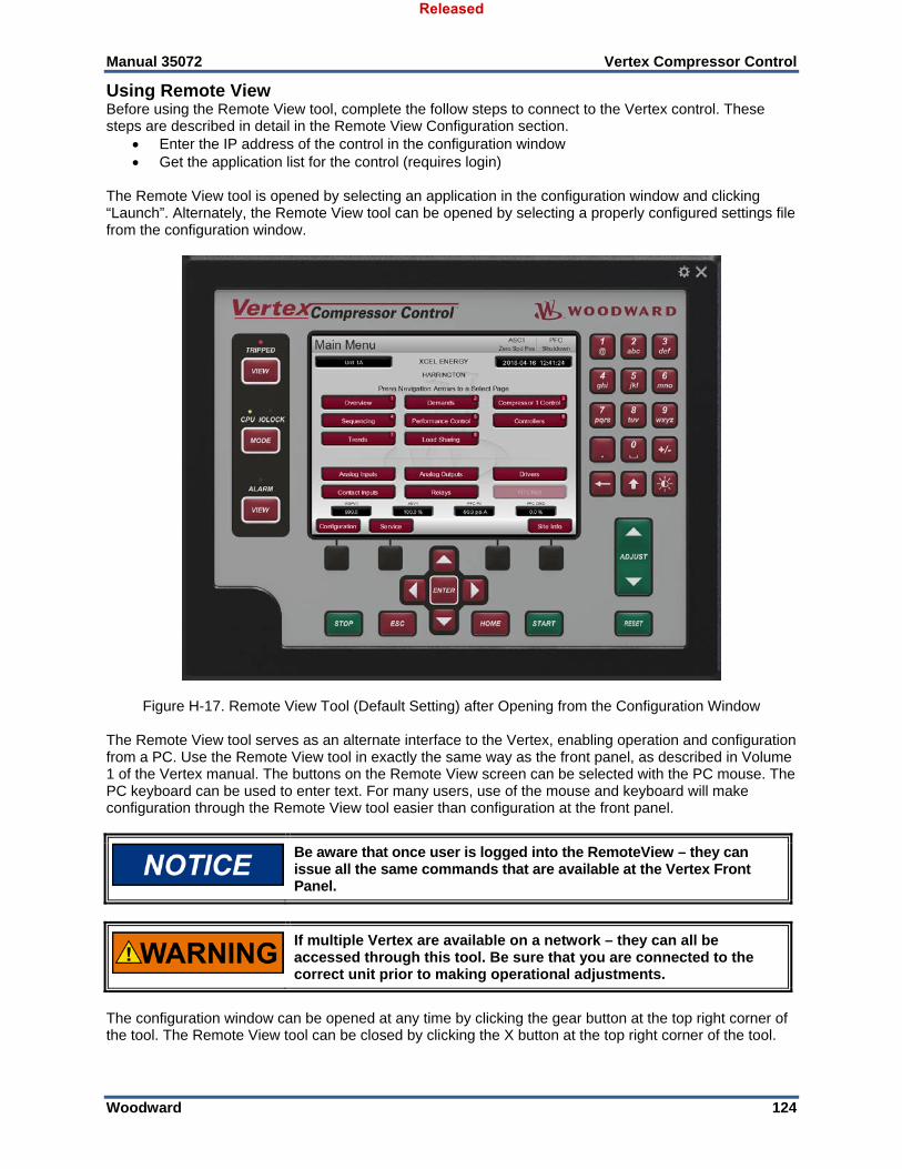
RemoteView This program provides a duplicate user interface as found on the front panel of the local Vertex control itself. It will allow the user to log into the control from a PC on the same network and provides full access to the control, with the exception of the Emergency Stop (which is a hardwired button directly integrated into the hardware. Users can log in at any User Level with this tool. It will run for up to 2 hours without a license. For continuous operation of this tool, a runtime license can be purchased.
Released
Manual 35072 Vertex Compressor Control
Woodward 10
Chapter 12. Application Notes
Overview This chapter is provided to give users an idea of the Vertex Compressor Control’s capabilities, and how to apply them to a system. Typical applications are schematically shown and their functionality explained. Programming and operational notes are given for each application to assist application programmers in configuring the Vertex for their application. The intent of the application examples in this section is to overview how to configure and operate the Vertex from a high level. The configuration options shown meet the minimum requirements for the application types. Details on each configuration parameter are given in Volume1 and a specific example with details on each parameter configured are given in Volume3.
Example Applications The example applications in this chapter do not show every possible control configuration or combination. However, these examples can also be used as a reference to apply any of the controlling combinations or parameters not listed or shown. To apply a desired control parameter or combination not shown, refer to one or more of the typical application configurations that are shown and resemble the control configuration desired, then substitute the shown control parameters with the required control parameters. To apply a desired control parameter or combination not shown, refer to one or more of the typical application configurations that are shown and resemble the control configuration desired, then substitute the shown control parameters with the required control parameters. The examples shown in this chapter are summarized as follows: Example 1: Single anti-surge loop Example 2: Single anti-surge loop with Performance control on compressor suction pressure via IGV
positioning Example 3: Single anti-surge loop with Performance control on compressor discharge pressure via
discharge throttle valve positioning and load sharing with control on the common discharge header pressure
Example 4: Two anti-surge loops Example 5: Two anti-surge loops with Performance control on compressor discharge pressure via
speed control setpoint Example 6: Two anti-surge loops with Performance control on compressor suction pressure via
suction throttle valve and load sharing with control on the common discharge header pressure
Released
Manual 35072 Vertex Compressor Control
Woodward 11
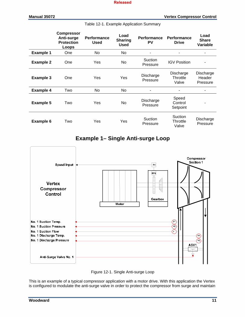
Table 12-1. Example Application Summary
Compressor Anti-surge Protection
Loops
Performance Used
Load Sharing
Used
Performance PV
Performance Drive
Load Share
Variable
Example 1 One No No - - -
Example 2 One Yes No Suction
Pressure IGV Position -
Example 3 One Yes Yes Discharge Pressure
Discharge Throttle Valve
Discharge Header
Pressure
Example 4 Two No No - - -
Example 5 Two Yes No Discharge Pressure
Speed Control Setpoint
-
Example 6 Two Yes Yes Suction
Pressure
Suction Throttle Valve
Discharge Pressure
Example 1– Single Anti-surge Loop
Figure 12-1. Single Anti-surge Loop This is an example of a typical compressor application with a motor drive. With this application the Vertex is configured to modulate the anti-surge valve in order to protect the compressor from surge and maintain
Released
Manual 35072 Vertex Compressor Control
Woodward 12
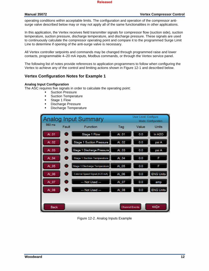
operating conditions within acceptable limits. The configuration and operation of the compressor anti-surge valve described below may or may not apply all of the same functionalities in other applications. In this application, the Vertex receives field transmitter signals for compressor flow (suction side), suction temperature, suction pressure, discharge temperature, and discharge pressure. These signals are used to continuously calculate the compressor operating point and compare it to the programmed Surge Limit Line to determine if opening of the anti-surge valve is necessary. All Vertex controller setpoints and commands may be changed through programmed raise and lower contacts, programmable 4–20 mA inputs, Modbus commands, or through the Vertex service panel. The following list of notes provide references to application programmers to follow when configuring the Vertex to achieve any of the control and limiting actions shown in Figure 12-1 and described below. Vertex Configuration Notes for Example 1 Analog Input Configuration The ASC requires five signals in order to calculate the operating point:
Suction Pressure Suction Temperature Stage 1 Flow Discharge Pressure Discharge Temperature
This selection enables the Anti-surge Control (ASC) 1 protection routines and selects the operating point equation.
Compressor Driver – (Motor Driven)
This selection is used to drive the appropriate graphics in the GUI. Speed Sensor Selection – (Checked)
When checked, this enables the speed signal to be used for zero speed detection and online detection sequencing routines. If this selection is checked, ensure that speed sensor is configured in IO channels.
ASC1 Configuration – Compressor Layout
Released
Manual 35072 Vertex Compressor Control
Woodward 14
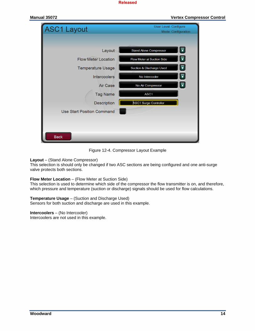
Figure 12-4. Compressor Layout Example Layout – (Stand Alone Compressor) This selection is should only be changed if two ASC sections are being configured and one anti-surge valve protects both sections. Flow Meter Location – (Flow Meter at Suction Side) This selection is used to determine which side of the compressor the flow transmitter is on, and therefore, which pressure and temperature (suction or discharge) signals should be used for flow calculations. Temperature Usage – (Suction and Discharge Used) Sensors for both suction and discharge are used in this example. Intercoolers – (No Intercooler) Intercoolers are not used in this example.
Released
Manual 35072 Vertex Compressor Control
Woodward 15
ASC1 Online Detection Configuration:
Figure 12-5. Antisurge Control > Online Detection Example Use Minimum Speed Level – (YES, 6000RPM) When the box is checked, if speed is above the Level setpoint the online condition is met and the control will slowly close the anti-surge valve until any of the automatic anti-surge routines take control. The ASC is now configured for use according to the compressor layout in this example. The remaining configuration of the ASC will be specific for each application. The following lists the remaining sections of the control that need to be configured: 1) Gas Characteristics: provide data for the process gas being used; MW, Specific Heat Ratio,
Compressibility 2) Flow Element: Input the Flow Metering Device specifications and calibrate 3) Anti-surge Valve: Set minimum position, Overstroke, or enable gain compensation 4) Compressor Mapping: Set the rated conditions and define the compressor Surge Limit Line using
engineering units from the OEM performance map. 5) Antisurge Control:
a. Sequencing: Start/Shutdown Positions, Online Detection, Valve Ramp Rates, NSD/Purge b. Surge Detection: Set the surge detection methods and actions to be taken on a surge event c. Surge Protection: Set the Control Margin, Boost Margin, and Amount, Consecutive Surge action,
and ASV Feedback signal settings. d. Signal Conditioning: determine and set the fallback strategies for Analog Input signal failures;
Last Good Value, Default Values, Smart Temperature, Signal Noise Filtering settings, and control mode actions on flow signal fault
e. PIDs: Set the initial ASC PID gains, Rate Controller settings, Valve Freeze, P1/P2 Override PIDs f. Decoupling: overall decoupling settings, speed decoupling settings, decoupling signal selection
Volume 1 provides descriptions for each configuration parameter in the sections above. Volume 3 provides a specific example for how to configure each of these sections for a Natural Gas compressor application. Not all settings listed in the sections above are required and will be enabled based on the requirements of the application. The settings are defaulted to safe, conservative values.
Released
Manual 35072 Vertex Compressor Control
Woodward 16
Trips: Within this example the compressor train can be tripped by several devices, one of these devices is the Vertex control. To provide feedback to the Vertex control that the compressor train is tripped, a contact from the trip string is wired into the External Emergency Shutdown input (DI01). With this application, the ‘trip’ annunciation should only occur if the Vertex tripped the compressor train and not annunciate when the other external devices shuts down the unit (Train Parameters: External Trips in Trip Relay ?–No.) Because the Vertex initiated shutdown relay is used in the trip string to shut down the train, additional relays are required for annunciating any train trip and annunciating a Vertex initiated trip. Relay #3 was programmed to annunciate any train trip as follows: (Relays: Use Relay #3–Yes ; Relay #3 is a Level Switch?–No ; Relay #3 Energizes on–Shutdown Condition). Relay #4 was programmed to indicate a Vertex initiated trip as follows: (Relays: Use Relay #4–Yes. Relay #4 is a Level Switch?–No. Relay #4 Energizes on–Trip Relay) Note that Relay #4 de-energizes on a trip condition (excluding external trip inputs) and Relay #3 energizes on a trip (shutdown) condition. Starting and Operation Notes for Example 1 When tripped, the Vertex will position the ASV at the ‘Position just After Shutdown’ setting (Antisurge Control > Sequencing). Once all trip conditions are cleared, the Vertex will continue to position the ASV at the ‘Position just After Shutdown’ until the Zero Speed (or current) level is surpassed.
Figure 12-6. Antisurge Control Tripped When the Zero Speed level is surpassed, the ASV will be positioned at the ‘Position During Startup’. The ASV will remain in this position until the online conditions are met. Unless defined differently, these three conditions are set at the same positions (100%). In this example, once the Online condition of 6000RPM is met for a configurable delay time, the control will slowly close the anti-surge valve until any of the automatic anti-surge routines take control (if in Auto Mode). As soon as the Online conditions are met and the valve begins ramping, the anti-surge protections are enabled and active. The control will continuously monitor the operating point of the compressor and determine if opening of the ASV is necessary. The operating point can be monitored on the Compressor Map page. The Control
Released
Manual 35072 Vertex Compressor Control
Woodward 17
Signals panel displays the current value for all field signals in engineering units. The Operating Point is displayed as a single value, the WSPV, and is a function of the compressor actual flow (x-axis on the Compressor Map) and the polytropic head (y-axis on the Compressor Map). A value of 100 WSPV indicates that the operating point is on the Surge Control Line, and the ASV will begin to open in order to move the operating point away from surge. While the WSPV is greater than 100, the ASV will tend to have 0.0% demand. As the WSPV moves less than 100, the ASV is opened according to the configured anti-surge protection and response routines (described in detail in Volume 1). The control will remain in this state of monitoring the operating point to modulate the ASV as necessary indefinitely, until a trip or STOP command is received or an Online condition is no longer met.
Figure 12-7. Compressor Map
Stopping Notes for Example 1 When the compressor is ready to be brought offline, the Normal Stop (or Normal Shutdown/ Controlled Shutdown, NSD) command can be issued to begin ramping the ASV valve to the Start Position at the NSD Rate. The Normal Stop command can be sent from the Vertex front panel (STOP button), discrete input, or Modbus.
Released
Manual 35072 Vertex Compressor Control
Woodward 18
Figure 12-8. Initiate Normal Stop
Once the ASV reaches the Start Position, the Normal Shutdown is considered complete. At this time, the prime mover should be taken offline. If “Trip on NSD Complete” is selected, then the Vertex will trip once the Normal Shutdown is complete. If “Manual w/ Backup on NSD Complete” is selected, the ASC will transfer to Manual With Backup Mode when the Normal Shutdown is complete. This allows the ASV to remain at the Start Position until the Online Detection conditions are no longer met as the prime mover is brought offline.
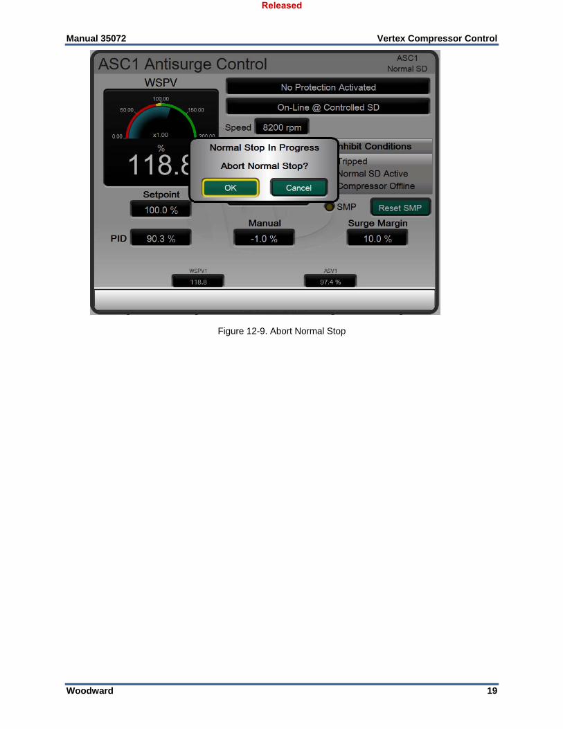
The Normal Stop can be aborted at any time before the ASV reaches the Start Position by pressing the STOP button again on the front panel, and selecting OK on the Abort Normal Shutdown sequence popup. If the Normal Shutdown is aborted and the ASC is in AUTO, the control will begin ramping the valve back to zero demand. If a Trip signal or condition is received, the ASV is instantly stepped to the Position after Shutdown setting.
Released
Manual 35072 Vertex Compressor Control
Woodward 19
Figure 12-9. Abort Normal Stop
Released
Manual 35072 Vertex Compressor Control
Woodward 20
Example 2– Single Anti-Surge Loop with Performance Control on Compressor Suction Pressure via IGV Positioning
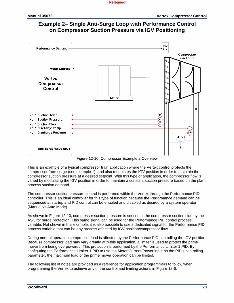
Figure 12-10. Compressor Example 2 Overview
This is an example of a typical compressor train application where the Vertex control protects the compressor from surge (see example 1), and also modulates the IGV position in order to maintain the compressor suction pressure at a desired setpoint. With this type of application, the compressor flow is varied by modulating the IGV position in order to maintain a constant suction pressure based on the plant process suction demand. The compressor suction pressure control is performed within the Vertex through the Performance PID controller. This is an ideal controller for this type of function because the Performance demand can be sequenced at startup and PID control can be enabled and disabled as desired by a system operator (Manual vs Auto Mode). As shown in Figure 12-10, compressor suction pressure is sensed at the compressor suction side by the ASC for surge protection. This same signal can be used for the Performance PID control process variable. Not shown in this example, it is also possible to use a dedicated signal for the Performance PID process variable that can be any process affected by IGV position/compressor flow. During normal operation compressor load is affected by the Performance PID controlling the IGV position. Because compressor load may vary greatly with this application, a limiter is used to protect the prime mover from being overpowered. This protection is performed by the Performance Limiter 1 PID. By configuring the Performance Limiter 1 PID to use the Motor Current/Power input as the PID’s controlling parameter, the maximum load of the prime mover operation can be limited. The following list of notes are provided as a reference for application programmers to follow when programming the Vertex to achieve any of the control and limiting actions in Figure 12-6.
Released
Manual 35072 Vertex Compressor Control
Woodward 21
Vertex Configuration Notes for Example 2 See example 1 for a guide to configuring and operating the ASC for the compressor surge protection loop. Performance Control: The Performance control loop is configured to receive compressor suction pressure through the ASC
1 Suction Pressure signal. (Compressor Configuration = ASC 1 Suction Pressure) The Performance control is inverted to allow the correct control loop action. To increase compressor
suction pressure, the IGV position must decrease the flow through the compressor. This is considered an indirect loop response action and requires the control to be inverted. (Inverted? Yes)
With this application, Setpoint Tracking is not used because the system’s pressure setpoint never
changes, thus system start-up is simpler. The Initial Setpoint is set to the desired system pressure. (Use Setpoint Tracking? No)
Figure 12-11. Performance Configuration Page 1 The Remote Setpoint analog input is not used to remotely set the Performance setpoint as the
system pressure never changes (Use Remote Setpoint? NO). The Performance control is not being used as a speed control setpoint, so Use Driver Limit Tracking
is not used. (Use Driver Limit Tracking? NO) In this application, the Performance demand is not being controlled remotely from an analog input.
(Use Remote Manual Demand? NO) The Performance Drive Type is set to IGV Position to display IGV graphics in the GUI and also allow
IGV position as an Online condition for the ASC 1 Online Detection routine.
Released
Manual 35072 Vertex Compressor Control
Woodward 22
Figure 12-12. Performance Configuration Page 2
The Reset Position allows the IGV position to be set after the shutdowns are cleared by prior to starting the unit to allow process gas to pressurize vessels and the compressor prior to starting the prime mover. (Reset Position = 10.0%)
The Start Position increases the IGV position once the Train Start Command is received in order to
allow adequate compressor flow for startup. (Startup Position = 25.0%) A delay after the Train Start Command prior to ramping to the Startup Position is not used. (Startup
Delay = 0.0s) A Train Start Command will be used in this application to indicate to the Vertex that the prime mover
has been started. (Use Remote Start? NO) In this application, the Performance control will transfer the AUTO control (PID control) as soon as
the Start Complete signal is received. (Use Manual Start? NO)
Released
Manual 35072 Vertex Compressor Control
Woodward 23
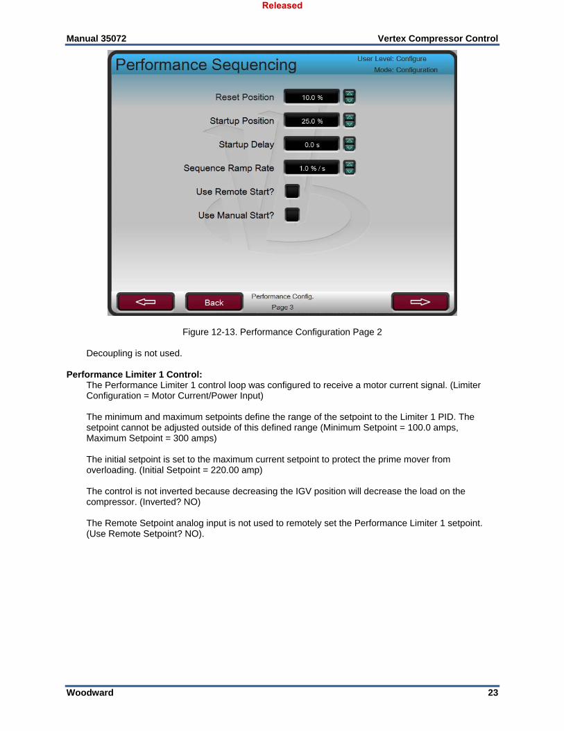
Figure 12-13. Performance Configuration Page 2 Decoupling is not used. Performance Limiter 1 Control: The Performance Limiter 1 control loop was configured to receive a motor current signal. (Limiter
Configuration = Motor Current/Power Input) The minimum and maximum setpoints define the range of the setpoint to the Limiter 1 PID. The
setpoint cannot be adjusted outside of this defined range (Minimum Setpoint = 100.0 amps, Maximum Setpoint = 300 amps)
The initial setpoint is set to the maximum current setpoint to protect the prime mover from
overloading. (Initial Setpoint = 220.00 amp) The control is not inverted because decreasing the IGV position will decrease the load on the
compressor. (Inverted? NO) The Remote Setpoint analog input is not used to remotely set the Performance Limiter 1 setpoint.
(Use Remote Setpoint? NO).
Released
Manual 35072 Vertex Compressor Control
Woodward 24
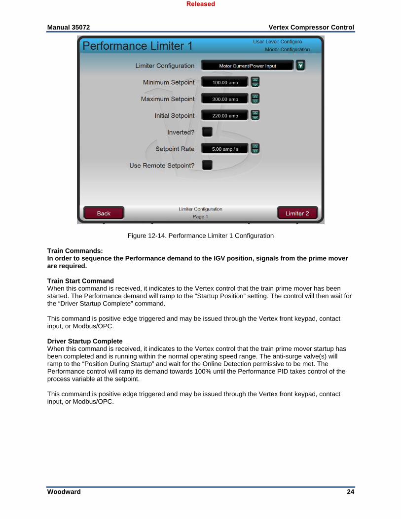
Figure 12-14. Performance Limiter 1 Configuration Train Commands: In order to sequence the Performance demand to the IGV position, signals from the prime mover are required. Train Start Command When this command is received, it indicates to the Vertex control that the train prime mover has been started. The Performance demand will ramp to the “Startup Position” setting. The control will then wait for the “Driver Startup Complete” command. This command is positive edge triggered and may be issued through the Vertex front keypad, contact input, or Modbus/OPC. Driver Startup Complete When this command is received, it indicates to the Vertex control that the train prime mover startup has been completed and is running within the normal operating speed range. The anti-surge valve(s) will ramp to the “Position During Startup” and wait for the Online Detection permissive to be met. The Performance control will ramp its demand towards 100% until the Performance PID takes control of the process variable at the setpoint. This command is positive edge triggered and may be issued through the Vertex front keypad, contact input, or Modbus/OPC.
Released
Manual 35072 Vertex Compressor Control
Woodward 25
Figure 12-15. Train Commands Contact Input Configuration Starting and Run Mode Notes for Example 2 While the Vertex is tripped, the Performance output is set at 0% demand. Upon reset, the Performance sequence ramp will ramp the output to the Reset Position. This allows process gas to pressurize vessels and the compressor prior to starting the prime mover. When the prime mover is started, a signal should be sent from the prime mover controller to the Vertex to indicate that the unit has been started. When the Train Start Command is received, the Performance sequence ramp will ramp the output to the Start Position. The Start Position is maintained until the Driver Startup Complete signal is received to allow adequate compressor flow for startup. Once the Vertex is in the Start Completed state, the Performance PID is activated on the LSS bus, and the Performance sequence ramp will begin to ramp the output towards 100% demand until the PID takes control of the output to control the compressor suction pressure at the setpoint. At any point during the start sequencing, the Performance Sequence ramp can be manually raised or lowered to position the Performance output as desired. While the Performance is starting, the ASC will being to ramp the ASV towards zero once the Online Detection conditions are all met. For this application, while the ASV valve is open, the compressor suction pressure will be increased by the recycle flow and the IGV position will not have as great of an influence on the compressor suction pressure, but will increase the flow through the compressor to try and control the pressure at the setpoint. As the ASV closes, the compressor suction pressure will begin to decrease, and the Performance control will independently bring the compressor suction pressure to the setpoint. With this application the Performance Limiter 1 control is programmed to limit the Performance output demand and keep the prime mover at or below the maximum load level. The Limiter 1 demand is always active on the LSS bus and can take control of the Performance output any time the load is too high. If suction pressure demand, and/or other system conditions try to force the prime mover to operate above its load limit setting, the Limiter 1 PID will take control of the Performance output to limit load. Once system conditions demand unit load below that of the Limiter 1 setpoint, the Performance PID will again take control of output to control compressor suction pressure at the setpoint.
Released
Manual 35072 Vertex Compressor Control
Woodward 26
Stopping Notes for Example 2 When the compressor is ready to be brought offline, the Normal Stop (or Normal Shutdown/ Controlled Shutdown, NSD) command can be sent to begin ramping the ASV valve to the Start Position at the NSD Rate. While the ASV valve is ramping open, the Performance control transitions to Manual Mode, holding the last output demand.
Once the ASV reaches the Start Position, the Performance demand beings ramping towards the Reset Position. Once the Reset Position is reached, the Normal Shutdown is considered complete. At this time, the prime mover should be taken offline. The Normal Stop can be aborted at any time before the Performance reaches the Reset Position by pressing the STOP button on the front panel, and selecting OK on the Abort Normal Shutdown sequence popup. If the Normal Shutdown is aborted and the ASC is in Auto Mode, and the ASV has not yet reached the Start Position, the control will begin ramping the ASV back to zero demand. If the normal shutdown is aborted after the ASV has reached the Start Position, there are two cases: 1) If an External Online command is used, the command must be resent in order to ramp the ASV back
to zero demand. 2) If an External Online command is not used, the ASC will remain at the Start Position in Manual with
Backup and an operator must place the control back into Auto Mode in order to ramp the ASV back to zero demand. Alternatively, the operator can manually close the ASV in Manual with Backup.
If the Normal Shutdown is aborted, the Performance control will always remain in Manual Mode at the last position.
Released
Manual 35072 Vertex Compressor Control
Woodward 27
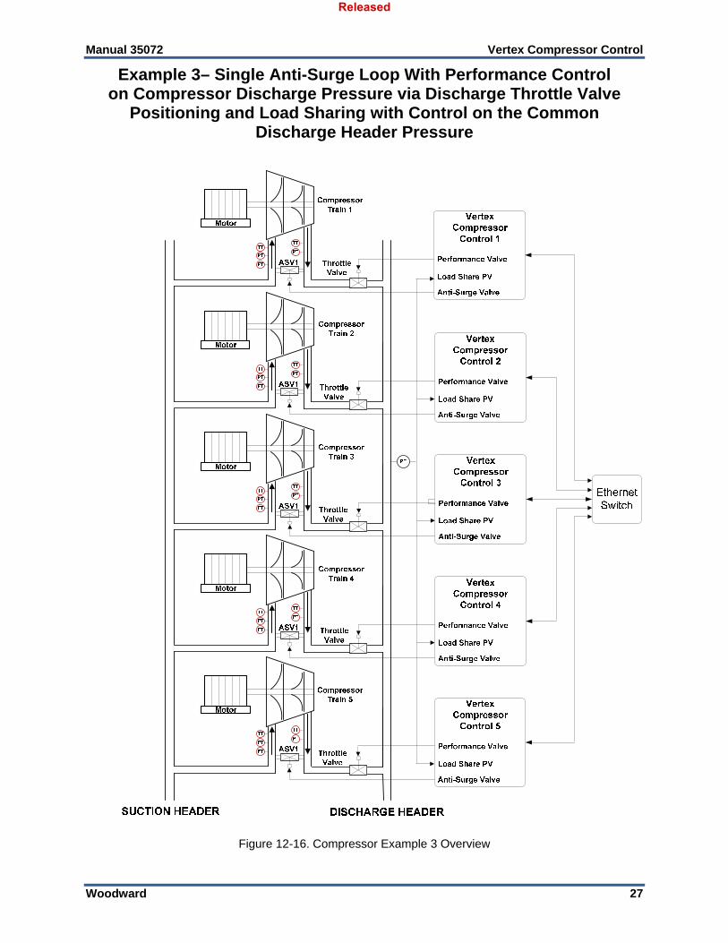
Example 3– Single Anti-Surge Loop With Performance Control on Compressor Discharge Pressure via Discharge Throttle Valve
Positioning and Load Sharing with Control on the Common Discharge Header Pressure
Figure 12-16. Compressor Example 3 Overview
Released
Manual 35072 Vertex Compressor Control
Woodward 28
This is an example of a typical compressor train application where the Vertex control protects the compressor from surge (see example 1), modulates a discharge throttle valve to control compressor discharge pressure in Performance control, and modulates the same discharge throttle valve to control a common discharge header in load sharing across 5 compressor trains. With this type of application, the compressor load through each compressor train is varied using the discharge throttle valves to maintain a constant header pressure and distribute the load across each compressor among the group equally. With this application compressor discharge pressure control is performed within the Vertex through the Performance PID controller. This process variable control is used prior to load sharing being enabled or any time when load sharing gets kicked out. As shown in Figure 12-16, compressor discharge pressure is monitored at the compressor discharge side by the ASC for surge protection. This same signal can be used for the Performance PID control process variable. The common discharge header pressure is monitored by one or more transmitters on the discharge header and sent to one or more Vertex units in the load sharing group. This parameter is shared between all Vertex units in the load sharing group and transmitter redundancy management determines a final validated signal to be used for control. During normal operation, each Vertex Load Sharing controller is used to modulate a desired discharge header pressure, and also to bias the load share controller in order to distribute the loading of each compressor equally among all five trains in the group. In this application, the load sharing parameter used is WSPV. In steady state, the discharge header pressure will be maintained at the Master Setpoint, and each compressor will be operating with the same WSPV operating point. The discharge throttle valves will be positioned as needed to maintain these conditions. Each Vertex controller in the load sharing group needs to know the operating conditions for all other units in the group. This is accomplished via Ethernet port 4 of each unit connected to a common Ethernet switch. During normal operation compressor load is affected by the Performance PID or Load Sharing PID controlling the discharge throttle valve position. Because compressor load may vary greatly with this application, a limiter is used to protect the prime mover from being overpowered. This protection is performed by the Performance Limiter 1 PID. By configuring the Performance Limiter 1 PID as a limiter and use the Motor Current/Power input as the PID’s controlling parameter, the prime mover’s maximum amount of load can be limited. The following list of notes are provided as a reference for application programmers to follow when programming the Vertex to achieve any of the control and limiting actions in Figure 12-16. Vertex Configuration Notes for Example 3 See Example 1 for a guide to configuring and operating the ASC for the compressor surge protection loop. See Example 2 for a guide to configuring the Performance Control and Performance Limiter 1. With this application, the following considerations were made different from Example 2: The Performance control loop was configured to receive compressor discharge pressure through the
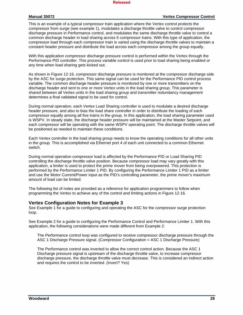
ASC 1 Discharge Pressure signal. (Compressor Configuration = ASC 1 Discharge Pressure) The Performance control was inverted to allow the correct control action. Because the ASC 1
Discharge pressure signal is upstream of the discharge throttle valve, to increase compressor discharge pressure, the discharge throttle valve must decrease. This is considered an indirect action and requires the control to be inverted. (Invert? Yes)
Released
Manual 35072 Vertex Compressor Control
Woodward 29
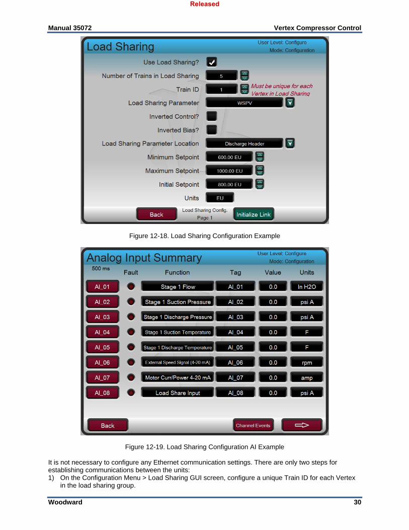
Figure 12-17. Performance Control Example 3 Load Sharing Control: Load Sharing functionality is required for this application (Use Load Sharing? YES) The total number of trains running in parallel and controlling the same discharge header is 5.
(Number of Trains in Load Sharing = 5) The Train ID for this example is 1. Each train must be configured with a unique ID. Each of the other
trains in the load sharing group must be configured with a different ID. (Train ID = 1) The Load Sharing Parameter for this application is WSPV. When load sharing is enabled across
multiple trains in the load sharing group, the load share controller will control each unit to the average of all units. (Load Sharing Parameter = WSPV)
The Load Sharing controller is positioning the discharge throttle valve in order to control the common
discharge header pressure. To increase the discharge header pressure, the discharge throttle valve must be increased. This is direct acting control. (Invert Control? NO)
The Load Sharing Parameter is controlled by biasing the Load Sharing PID controller setpoint. In this
application, to increase the WSPV the Discharge throttle valve must increase, which requires the Load Sharing Master Setpoint to be biased with a positive value. (Invert Bias? NO)
The common process variable is the discharge header. This is only used for display purposes. (Load
Sharing Parameter Location = Discharge Header) The minimum and maximum setpoints define the range of the setpoint to the Load Sharing PID. The
setpoint cannot be adjusted outside of this defined range (Minimum Setpoint = 600.0 psi A, Maximum Setpoint = 1000.0 psi A)
Released
Manual 35072 Vertex Compressor Control
Woodward 30
Figure 12-18. Load Sharing Configuration Example
Figure 12-19. Load Sharing Configuration AI Example It is not necessary to configure any Ethernet communication settings. There are only two steps for establishing communications between the units: 1) On the Configuration Menu > Load Sharing GUI screen, configure a unique Train ID for each Vertex
in the load sharing group.
Released
Manual 35072 Vertex Compressor Control
Woodward 31
2) Connect Ethernet Port 4 of each Vertex control to the common Ethernet switch. Starting and Run Mode Notes for Example 3 See Example 1 and Example 2 for details on ASC and Performance startup and operation. Once the ASC is Online and the Performance PID has control, the load sharing permissives are met. If the train is going to be the first train to join the load-sharing group, it will automatically become the Master Setpoint controller. Load sharing can be enabled from the Vertex front panel, discrete input, or Modbus. The load sharing PID tracks the Performance demand prior to being enabled to allow a bumpless transition between the two controllers. When enabled, the load-sharing PID becomes active on the Performance LSS and then will begin modulating the discharge throttle valve to maintain the discharge header pressure at the Master Setpoint value. If the train is the first train in the load-sharing group, a bias to the setpoint is not generated and the PID controls the header pressure to the Master Setpoint. In this application, each train’s Performance controller controls the local compressor discharge header pressure to reduce fighting between controllers while not in load sharing. As more trains are brought into control, they will control the discharge header pressure to the Master Setpoint by modulating their respective discharge throttle valves. Each controller will be using the same Master Setpoint and the same Validated Process signal, which get communicated over the Ethernet links. When multiple trains are active in the load-sharing group, only the Master Setpoint controller can move the header pressure setpoint. Changing the Master Setpoint will change the setpoint for all controllers in the load-sharing group. The Master Setpoint controller can be requested by any controller in the load-sharing group at any time. The command to request the Master Setpoint controller can be made from the Vertex front panel or Modbus. This allows operators to control the load-sharing group from any Vertex unit. When multiple trains are active in the load-sharing group, each controller controls the discharge header pressure and also controls its own WSPV to reach the average of all other trains in the load sharing group. In this way, the header pressure can be maintained at the Master Setpoint and all units will be operating at the same WSPV once steady state is reached. Volume 1 of this manual details the kick out conditions for load sharing. If a unit is kicked out of load sharing for any reason, the Performance PID becomes active controlling its local discharge pressure at the last value sensed at the time load sharing was disabled. Load sharing can be re-enabled once the load sharing permissives are met again. If Auto-Rejoin is configured, the control will fall back to Performance control after a kickout condition is active and remain there until the condition is no longer true, and then will automatically re-join the load-sharing group after a configurable delay time. Stopping Notes for Example When the compressor is ready to be brought offline, the Normal Stop (or Normal Shutdown/ Controlled Shutdown, NSD) command can be sent. When a Normal Stop is initiated, Load Sharing is disabled and Performance will transfer to Manual Mode and hold the discharge throttle valve at the last position as the ASV is ramped to the Startup Position. Example 1 and Example 2 detail the shutdown sequences once Load Sharing is disabled.
Released
Manual 35072 Vertex Compressor Control
Woodward 32
Example 4– Two Anti-Surge Loops
Figure 12-20. Compressor Example 4 Overview
The configuration of the second stage is done as described in Example 1 for ASC 1. In general, ASC 2 and ASC 1 calculate the operating point of each section and modulate their ASVs independently. All configuration parameters and routines available for ASC 1 are also available for ASC 2. Because the Vertex unit may not have enough IO channels to support the signals needed for both sections (depending on application – for air compressors with suction side from atmosphere, a limited IO set may be used), RTCNet IO Expansion modules will be necessary. The same IO functions can be selected on an RTCNet Node as the Vertex control. Please see chapter 5 for details on RTCNet IO Expansion. In this application, Motor current and speed are used for online detection. Please see Example 1 for descriptions on startup, operation, and stopping. The same functionality is available for ASC 2.
Released
Manual 35072 Vertex Compressor Control
Woodward 33
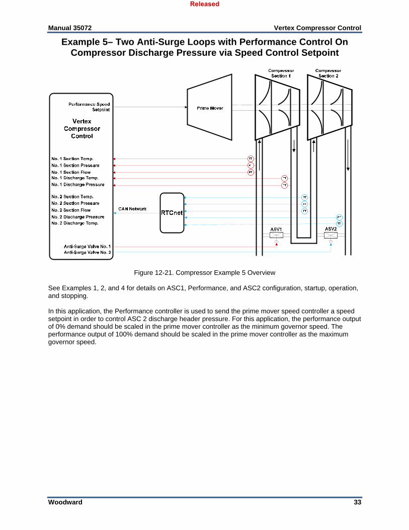
Example 5– Two Anti-Surge Loops with Performance Control On Compressor Discharge Pressure via Speed Control Setpoint
Figure 12-21. Compressor Example 5 Overview See Examples 1, 2, and 4 for details on ASC1, Performance, and ASC2 configuration, startup, operation, and stopping. In this application, the Performance controller is used to send the prime mover speed controller a speed setpoint in order to control ASC 2 discharge header pressure. For this application, the performance output of 0% demand should be scaled in the prime mover controller as the minimum governor speed. The performance output of 100% demand should be scaled in the prime mover controller as the maximum governor speed.
Released
Manual 35072 Vertex Compressor Control
Woodward 34
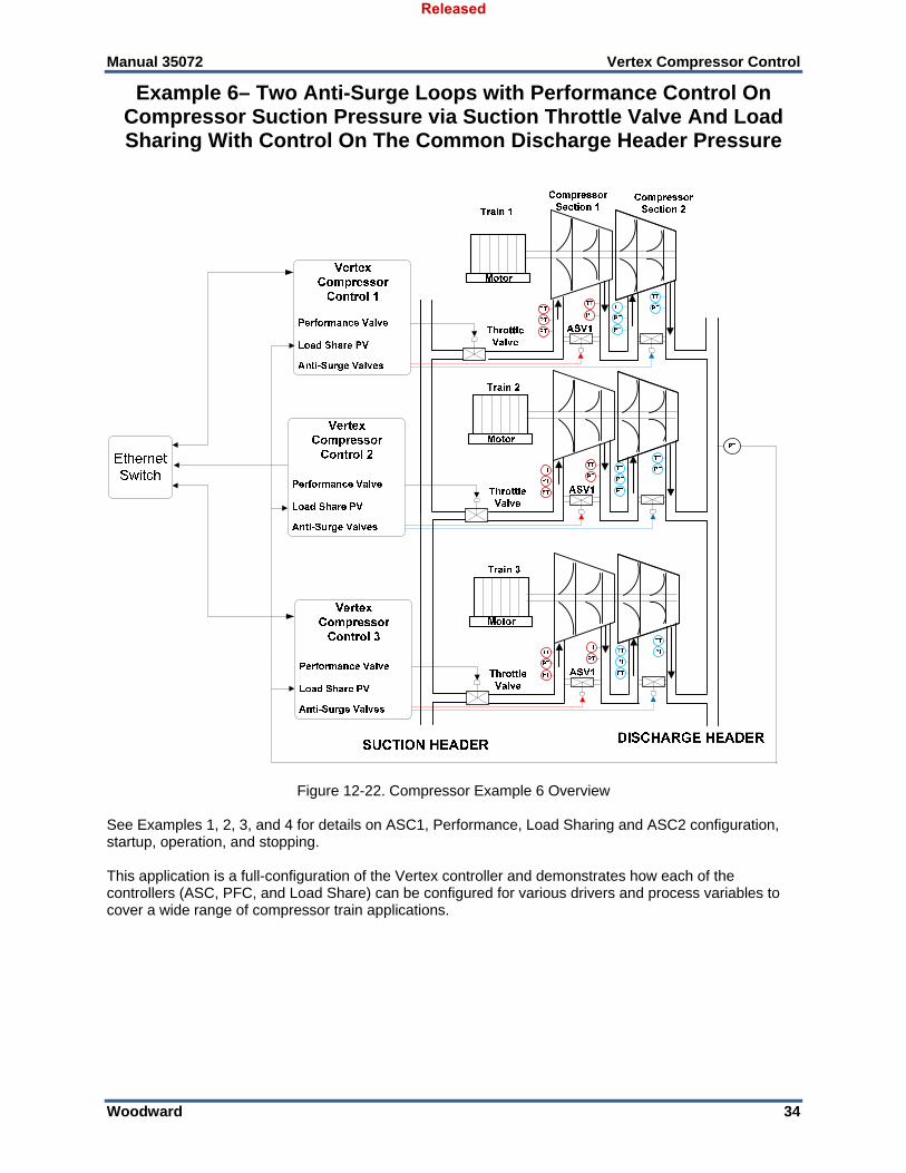
Example 6– Two Anti-Surge Loops with Performance Control On Compressor Suction Pressure via Suction Throttle Valve And Load Sharing With Control On The Common Discharge Header Pressure
Figure 12-22. Compressor Example 6 Overview
See Examples 1, 2, 3, and 4 for details on ASC1, Performance, Load Sharing and ASC2 configuration, startup, operation, and stopping. This application is a full-configuration of the Vertex controller and demonstrates how each of the controllers (ASC, PFC, and Load Share) can be configured for various drivers and process variables to cover a wide range of compressor train applications.
Released
Manual 35072 Vertex Compressor Control
Woodward 35
Chapter 13. Operator Interface
Introduction Interface to the control may be performed through the Vertex’s service panel (located on the front of the control), remote switch contacts, analog inputs, meter readouts, relays, or a Modbus communications line to an operator interface device.
Screen Tutorial
The Vertex has a detailed Tutorial that is always accessible through the Service Menu. It provides ‘On-Screen’ help on topics such as Navigation, User Levels, Operating Modes, how to adjust parameters and more. The User should familiarize themselves with these screens
Graphical Display and Key Inputs The control’s service panel consists of hard key command buttons, soft key command buttons, and a Graphical User Interface screen.
Figure 13-1 Vertex Keypad and Display The system operator uses the service panel to communicate with the Vertex system. The service panel can be used only occasionally to communicate with the system, or it can continuously monitor user interface pages for the operator to view.
Released
Manual 35072 Vertex Compressor Control
Woodward 36
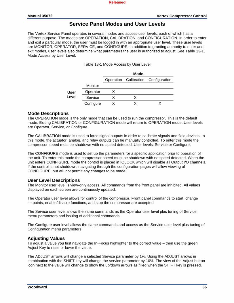
Service Panel Modes and User Levels The Vertex Service Panel operates in several modes and access user levels, each of which has a different purpose. The modes are OPERATION, CALIBRATION, and CONFIGURATION. In order to enter and exit a particular mode, the user must be logged in with an appropriate user level. These user levels are MONITOR, OPERATOR, SERVICE, and CONFIGURE. In addition to granting authority to enter and exit modes, user levels also determine what parameters the user is authorized to adjust. See Table 13-1, Mode Access by User Level.
Table 13-1 Mode Access by User Level
Mode
Operation Calibration Configuration
User Level
Monitor
Operator X
Service X X
Configure X X X Mode Descriptions The OPERATION mode is the only mode that can be used to run the compressor. This is the default mode. Exiting CALIBRATION or CONFIGURATION mode will return to OPERATION mode. User levels are Operator, Service, or Configure. The CALIBRATION mode is used to force signal outputs in order to calibrate signals and field devices. In this mode, the actuator, analog, and relay outputs can be manually controlled. To enter this mode the compressor speed must be shutdown with no speed detected. User levels: Service or Configure. The CONFIGURE mode is used to set up the parameters for a specific application prior to operation of the unit. To enter this mode the compressor speed must be shutdown with no speed detected. When the unit enters CONFIGURE mode the control is placed in IOLOCK which will disable all Output I/O channels. If the control is not shutdown, navigating through the configuration pages will allow viewing of CONFIGURE, but will not permit any changes to be made. User Level Descriptions The Monitor user level is view-only access. All commands from the front panel are inhibited. All values displayed on each screen are continuously updated. The Operator user level allows for control of the compressor. Front panel commands to start, change setpoints, enable/disable functions, and stop the compressor are accepted. The Service user level allows the same commands as the Operator user level plus tuning of Service menu parameters and issuing of additional commands. The Configure user level allows the same commands and access as the Service user level plus tuning of Configuration menu parameters. Adjusting Values To adjust a value you first navigate the In-Focus highlighter to the correct value – then use the green Adjust Key to raise or lower the value. The ADJUST arrows will change a selected Service parameter by 1%. Using the ADJUST arrows in combination with the SHIFT key will change the service parameter by 10%. The view of the Adjust button icon next to the value will change to show the up/down arrows as filled when the SHIFT key is pressed.
Released
Manual 35072 Vertex Compressor Control
Woodward 37
When making adjustments to an analog value that is at 0.00, initial movement will be very small and you may take a few seconds for the display to show the value is moving – be patient.
To make a direct entry, the current displayed value must be within 10% of the value to be entered. To make direct numeric entries: 1. Bring the displayed value to within 10% of the value to be entered 2. Press the ENTER key 3. Press the numerical keys to input the value 4. Press ENTER again. If the value entered is less than the value displayed by more than 10% or greater than the value displayed by more than 10%, an appropriate message will be displayed indicating the value entered is too large or too small. The exception to this 10% adjustment rule is that it is NOT applied if the control is in Configuration Mode. In this mode, any direct entry in the appropriate range will be accepted.
When making a direct entry of a negative number (for example, a sensor range of –50 to 200), enter the value first and then press the +/– key.
When using the SERVICE mode, refer to the Service Mode worksheet in Appendix B.
Released
Manual 35072 Vertex Compressor Control
Woodward 38
Chapter 14. Service Menu Procedures
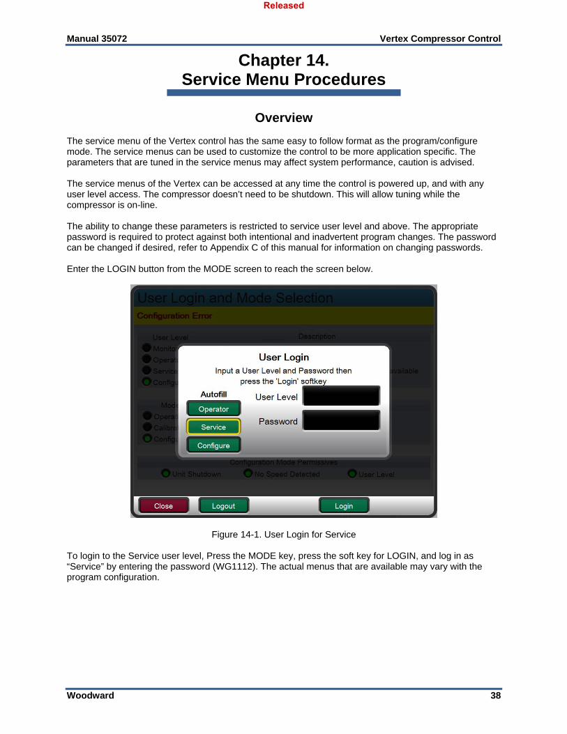
Overview The service menu of the Vertex control has the same easy to follow format as the program/configure mode. The service menus can be used to customize the control to be more application specific. The parameters that are tuned in the service menus may affect system performance, caution is advised. The service menus of the Vertex can be accessed at any time the control is powered up, and with any user level access. The compressor doesn’t need to be shutdown. This will allow tuning while the compressor is on-line. The ability to change these parameters is restricted to service user level and above. The appropriate password is required to protect against both intentional and inadvertent program changes. The password can be changed if desired, refer to Appendix C of this manual for information on changing passwords. Enter the LOGIN button from the MODE screen to reach the screen below.
Figure 14-1. User Login for Service To login to the Service user level, Press the MODE key, press the soft key for LOGIN, and log in as “Service” by entering the password (WG1112). The actual menus that are available may vary with the program configuration.
Released
Manual 35072 Vertex Compressor Control
Woodward 39
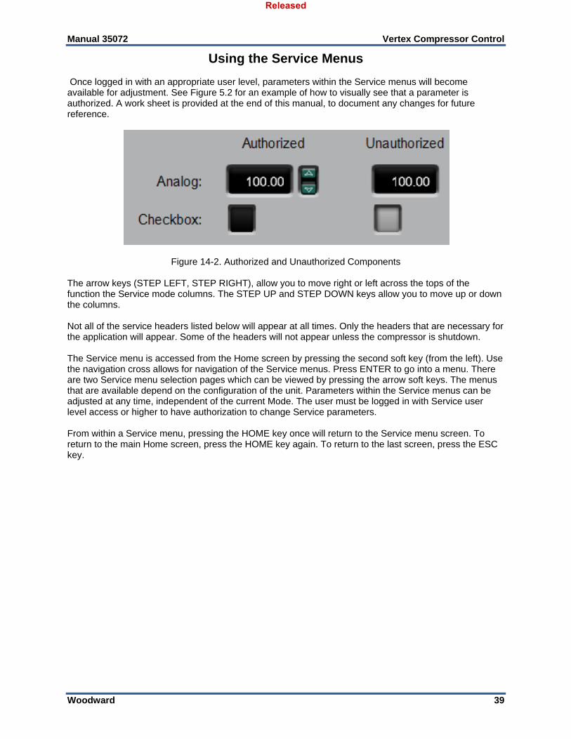
Using the Service Menus Once logged in with an appropriate user level, parameters within the Service menus will become available for adjustment. See Figure 5.2 for an example of how to visually see that a parameter is authorized. A work sheet is provided at the end of this manual, to document any changes for future reference.
Figure 14-2. Authorized and Unauthorized Components The arrow keys (STEP LEFT, STEP RIGHT), allow you to move right or left across the tops of the function the Service mode columns. The STEP UP and STEP DOWN keys allow you to move up or down the columns. Not all of the service headers listed below will appear at all times. Only the headers that are necessary for the application will appear. Some of the headers will not appear unless the compressor is shutdown. The Service menu is accessed from the Home screen by pressing the second soft key (from the left). Use the navigation cross allows for navigation of the Service menus. Press ENTER to go into a menu. There are two Service menu selection pages which can be viewed by pressing the arrow soft keys. The menus that are available depend on the configuration of the unit. Parameters within the Service menus can be adjusted at any time, independent of the current Mode. The user must be logged in with Service user level access or higher to have authorization to change Service parameters. From within a Service menu, pressing the HOME key once will return to the Service menu screen. To return to the main Home screen, press the HOME key again. To return to the last screen, press the ESC key.
Released
Manual 35072 Vertex Compressor Control
Woodward 40
Service Menus – HOME screen The following figures show the menu list of pages that are available through the Service Menus. The Tutorial pages and the Save Settings (updating tunable values on the control) are always available on the black SoftKey buttons without any focus or navigation. Features that exist in the control, but are not configured will be shown in reduced opacity so the user is aware of the feature. Pressing Enter while on these pages will not navigate to these pages. This is different from the HOME page, where unused functions are completely removed to avoid confusion and simplify navigation.
Figure 14-3 Service Menu The service menus can be used while the compressor is running or shut down. Access to the Service menus requires the user to be logged in with a Service user level or higher. The intent of the organization and arrangement of the pages is that page 1 contains the page that directly relate to the previous Vertex Service header menus on the 2 line display. Page 2 contains features that are new with this product. This mode can also be used to make direct numeric entries. However, because this mode is intended to be used while the compressor is running, the Service Panel will accept the entry of numeric values for a block only if the proposed change is small. Service Menu list: Communications—change or view the default settings for Ethernet, Serial, and Modbus
communication links. Alarms—monitor or change the program or default settings of; is trip an alarm indication; blink alarm
relay; jump to alarm screen; configurable alarms 1,2, and 3; configurable alarms for inlet pressure, exhaust pressure, and valve demand vs position feedback;
Actuator Linearization—provides actuator 1 and actuator 2 output linearization adjustments; Real Time Clock – set date and time settings. Custom Trend – trend display; signal selection; time window for trend display. Data Log – manually start and stop data log collection. Operation Values – view operation log values. Adjust compressor operation values. Screen Settings – screen saver delay; select auto login as operator; Each of the Service menu parameters are described in detail below.
Released
Manual 35072 Vertex Compressor Control
Woodward 41
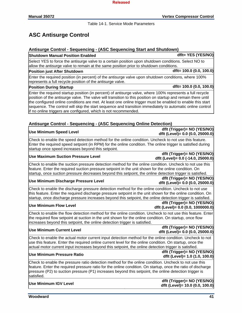
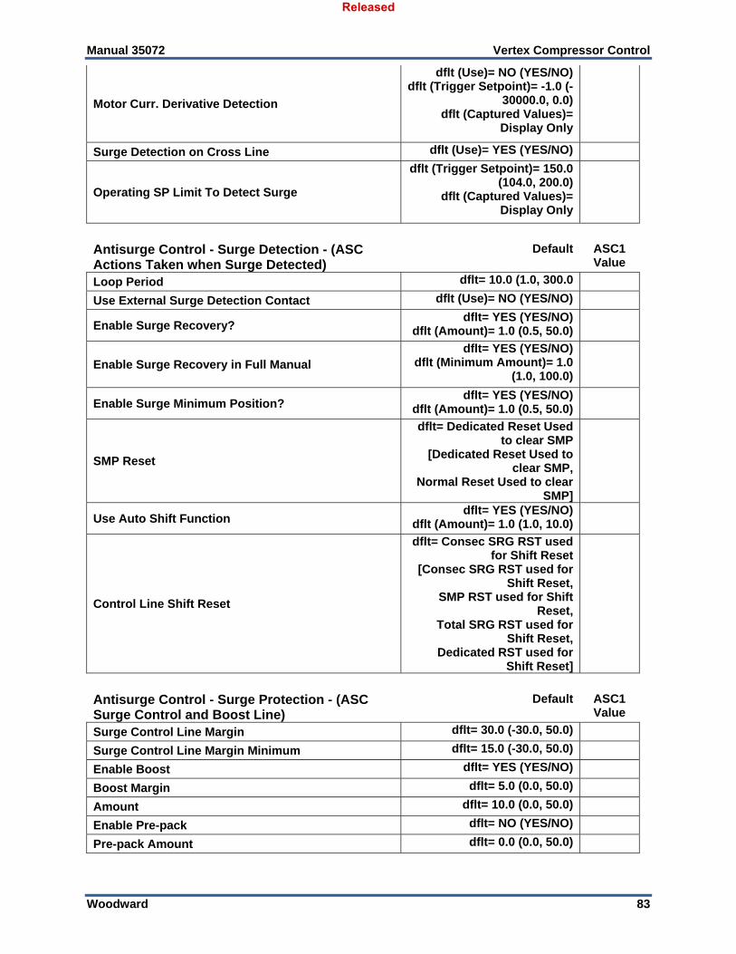
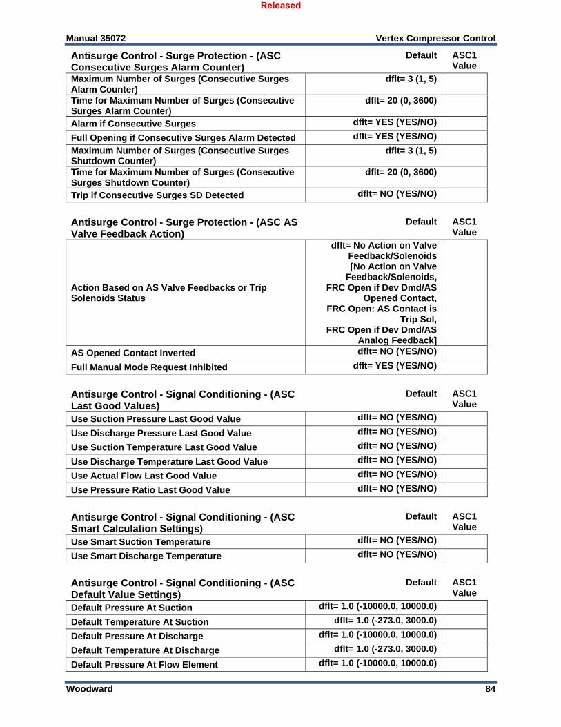
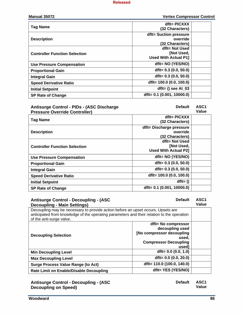
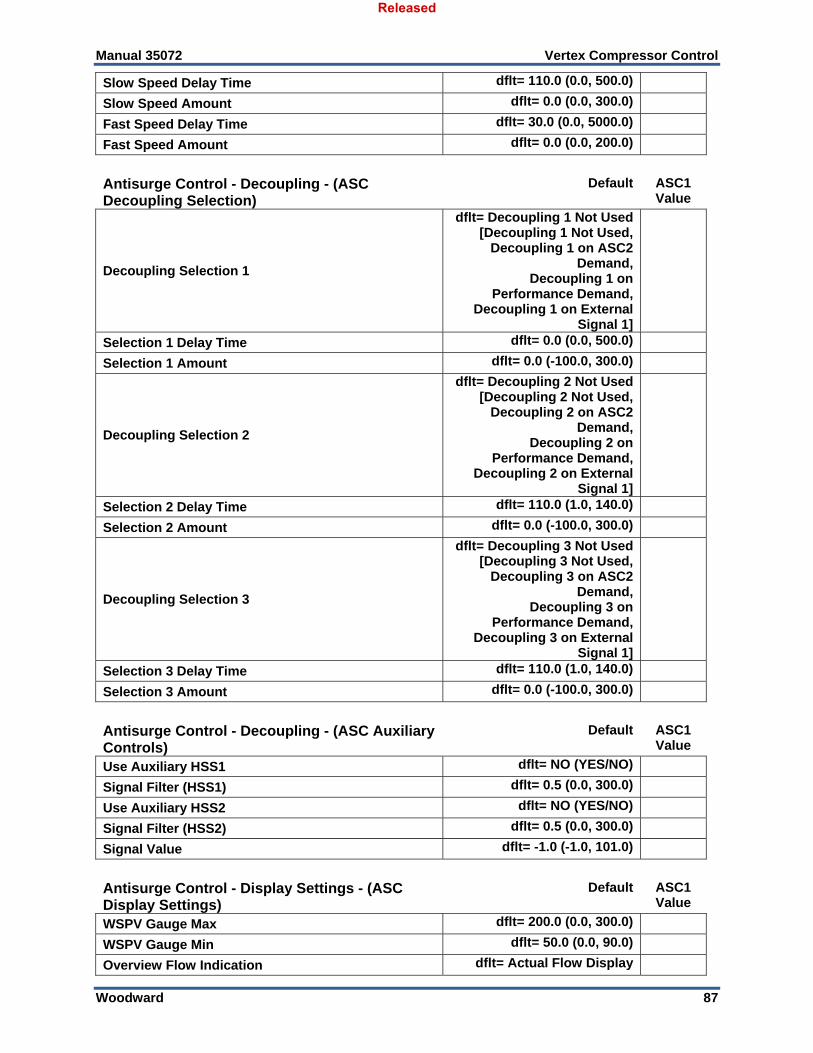
Table 14-1. Service Mode Parameters
ASC Antisurge Control
Antisurge Control - Sequencing - (ASC Sequencing Start and Shutdown) Shutdown Manual Position Enabled dflt= YES (YES/NO)
Select YES to force the antisurge valve to a certain position upon shutdown conditions. Select NO to allow the antisurge valve to remain at the same position prior to shutdown conditions.
Position just After Shutdown dflt= 100.0 (0.0, 100.0)
Enter the required position (in percent) of the antisurge valve upon shutdown conditions, where 100% represents a full recycle position of the antisurge valve.
Position During Startup dflt= 100.0 (0.0, 100.0)
Enter the required startup position (in percent) of antisurge valve, where 100% represents a full recycle position of the antisurge valve. The valve will transition to this position on startup and remain there until the configured online conditions are met. At least one online trigger must be enabled to enable this start sequence. The control will skip the start sequence and transition immediately to automatic online control if no online triggers are configured, which is not recommended.
Antisurge Control - Sequencing - (ASC Sequencing Online Detection)
Use Minimum Speed Level dflt (Trigger)= NO (YES/NO)
dflt (Level)= 0.0 (0.0, 25000.0)
Check to enable the speed detection method for the online condition. Uncheck to not use this feature. Enter the required speed setpoint (in RPM) for the online condition. The online trigger is satisfied during startup once speed increases beyond this setpoint.
Use Maximum Suction Pressure Level dflt (Trigger)= NO (YES/NO)
dflt (Level)= 0.0 (-14.0, 25000.0)
Check to enable the suction pressure detection method for the online condition. Uncheck to not use this feature. Enter the required suction pressure setpoint in the unit shown for the online condition. On startup, once suction pressure decreases beyond this setpoint, the online detection trigger is satisfied.
Use Minimum Discharge Pressure Level dflt (Trigger)= NO (YES/NO)
dflt (Level)= 0.0 (0.0, 25000.0)
Check to enable the discharge pressure detection method for the online condition. Uncheck to not use this feature. Enter the required discharge pressure setpoint in the unit shown for the online condition. On startup, once discharge pressure increases beyond this setpoint, the online detection trigger is satisfied.
Use Minimum Flow Level dflt (Trigger)= NO (YES/NO)
dflt (Level)= 0.0 (0.0, 1000000.0)
Check to enable the flow detection method for the online condition. Uncheck to not use this feature. Enter the required flow setpoint at suction in the unit shown for the online condition. On startup, once flow increases beyond this setpoint, the online detection trigger is satisfied.
Use Minimum Current Level dflt (Trigger)= NO (YES/NO)
dflt (Level)= 0.0 (0.0, 25000.0)
Check to enable the actual motor current input detection method for the online condition. Uncheck to not use this feature. Enter the required online current level for the online condition. On startup, once the actual motor current input increases beyond this setpoint, the online detection trigger is satisfied.
Use Minimum Pressure Ratio dflt (Trigger)= NO (YES/NO)dflt (Level)= 1.0 (1.0, 100.0)
Check to enable the pressure ratio detection method for the online condition. Uncheck to not use this feature. Enter the required pressure ratio for the online condition. On startup, once the ratio of discharge pressure (P2) to suction pressure (P1) increases beyond this setpoint, the online detection trigger is satisfied.
Use Minimum IGV Level dflt (Trigger)= NO (YES/NO)dflt (Level)= 10.0 (0.0, 100.0)
Released
Manual 35072 Vertex Compressor Control
Woodward 42
Check to enable the IGV detection method for the online condition. Uncheck to not use this feature. Enter the required pressure ratio for the online condition. On startup, once the IGV value increases beyond this setpoint, the online detection trigger is satisfied.
Use External Contact dflt (Trigger)= NO (YES/NO)
Check to enable the auxiliary binary input for online condition. Uncheck to not use this feature. This auxiliary input can be through Modbus or hardwired.
Delay Timer for Online Detection dflt (Level)= 10.0 (0.0, 300.0)
Enter a delay time (in seconds) for online detection to complete once any one of the online triggers is satisfied. After the delay time has passed, the control will slowly close the anti-surge valve until the automatic antisurge routines take control.
Antisurge Control - Sequencing - (ASC Sequencing Valve Rates) Automatic Close Rate dflt (Level)= 1.0 (0.0, 10.0)
Enter the ramp rate value, in percent per second, to be used by the automatic open-loop routines when ramping down the anti-surge valve.
Offline/Start Rate dflt (Level)= 1.0 (0.1, 100.0)
Enter the ramp rate value, in percent per second, to be used during start or when the compressor is offline.
NSD Rate dflt (Level)= 1.0 (0.1, 100.0)
Enter the ramp rate value, in percent per second, to be used during controlled shutdown. The compressor must be Online for this rate to be used during a controlled shutdown, otherwise, the Offline/Start Rate is used.
Enter the slow ramp rate value, in percent per second, to be used when the raise or lower valve command is requested in the manual or manual with backup mode.
Delay for Fast Rate dflt (Level)= 3.0 (0.0, 30.0)
Enter the value, in seconds, to activate the fast rate when the raise or lower valve command is requested in the manual or manual with backup mode.
Manual Raise/Lower Fast Rate dflt (Level)= 1.0 (0.0, 100.0)
Enter the fast ramp rate value, in percent per second, to be used after the delay time when the raise or lower valve command is requested in the manual or manual with backup mode.
Antisurge Control - Sequencing - (ASC Sequencing NSD/Purge)
Normal SD State
dflt= NSD on Train NSD Request[NSD on Train NSD Request,
NSD with Compressor 2 Offline,Not Used]
NSD on Train NSD Request: Normal shutdown trigger from Train NSD command. NSD with Compressor 2 Offline: Normal shutdown trigger when ASC2 goes offline. Not Used: Normal shutdown event is not configured.
Manual w/ Backup on NSD Complete dflt=YES (YES/NO)
If YES is selected, the ASC will transfer to Manual with Backup Mode once the Normal Shutdown is complete. This option allows the valve to remain at the Start Position if the Online Detection conditions are still TRUE. If NO is selected, the control will remain in AUTO control once the NSD is complete. Important: If NO is selected and the control is in AUTO and the compressor online conditions are met, the ASC will begin to ramp the ASV back to zero demand.
Released
Manual 35072 Vertex Compressor Control
Woodward 43
Purge Command
dflt= Purge Never Used[Purge Never Used,
Purge Disabled at Start,Purge Disabled at Online,
Purge Disabled on Speed Level,Purge Disabled on Motor Current Level,
Purge on Request Only]
Purge Never Used: Purge command is not available. Purge Disabled at Start: Purge option is disabled if start sequence initiated or ESD is active. Purge Disabled at Online: Purge option is disabled if compressor state is online or ESD is active. Purge Disabled On Speed Level: Purge option is disabled if actual speed is higher than trigger off Level or ESD is active. Purge Disabled On Motor Current Level: Purge option is disabled if actual motor current is higher than trigger off Level or ESD is active. Purge on Request Only: Purge option is always available except ESD status.
Purge Position dflt= 0.0 (0.0, 100.0)
Enter the required anti-surge valve position for a purge cycle during startup, i.e. 0 to 100% open.
Actual Speed Trigger Off Level dflt= 200.0 (10.0, 25000.0)
Enter the Speed in RPM that will disable the Purge sequence if speed is sensed above this level.
Actual Motor Trigger Off Level dflt= 200.0 (10.0, 25000.0)
Enter the Motor Current in Engineering Units that will disable the Purge sequence if Motor Current is sensed above this level.
dflt (Use)= NO (YES/NO)dflt (Trigger Setpoint)= 80.0 (1.0, 300.0)
dflt (Captured Values)= Display Only
Check to enable the flow derivative surge detection routine. This routine detects surge by monitoring the rate of change of calculated compressor flow. Enter the flow derivative value, in percent of suction volumetric flow units per second, above which the Surge Recovery and Surge Minimum Position routines, if enabled, are to be triggered. The set point is configured in percent to account for the wide range of most compression processes and to eliminate false triggers on noise at low flow levels. For example, if the current operating flow is 10,000 m3/hr and this set point is configured as 50%, a surge will be detected if the rate of flow change exceeds 5,000 m3/hr. However, the same derivative at a nominal flow rate of 50,000 m3/hr is only 10%, and could be caused by a noisy signal, not surge. Data from an actual surge event is helpful (recorded in the Captured Values column) in establishing an appropriate set point to exclude normal signal noise and process fluctuations.
Minimum Flow Detection dflt (Use)= NO (YES/NO)
dflt (Trigger Setpoint)= 1.0 (0.01, 100000000.0)
Check to enable the minimum flow surge detection routine. This routine, though included as a surge detection method, does not actually detect surge. It merely initiates the same open-loop Surge Recovery and Surge Minimum Position responses when the compressor operating point falls below the configured minimum flow set point. Enter the minimum flow value, in engineering units, of suction volumetric flow below which the Surge Recovery and Surge Minimum Position routines, if enabled, are to be triggered.
Disch. P. Derivative Detection dflt (Use)= NO (YES/NO)
dflt (Trigger Setpoint)= -100.0 (-1000000.0, 0.0)dflt (Captured Values)= Display Only
Released
Manual 35072 Vertex Compressor Control
Woodward 44
Check to enable the discharge pressure derivative surge detection routine. This routine detects surge by monitoring the rate of change of measured compressor discharge pressure. Enter the discharge pressure derivative value, in engineering units per second, above which the Surge Recovery and Surge Minimum Position routines, if enabled, are to be triggered. Data from an actual surge event is helpful in establishing an appropriate set point to exclude normal process fluctuations.
Suction P. Derivative Detection dflt (Use)= NO (YES/NO)
dflt (Trigger Setpoint)= 1.0 (0.0, 100000.0)dflt (Captured Values)= Display Only
Check to enable the suction pressure derivative surge detection routine. This routine detects surge by monitoring the rate of change of measured compressor suction pressure. Enter the suction pressure derivative value, in engineering units per second, above which the Surge Recovery and Surge Minimum Position routines, if enabled, are to be triggered. Data from an actual surge event is helpful in establishing an appropriate set point to exclude normal process fluctuations.
Speed Derivative Detection dflt (Use)= NO (YES/NO)
dflt (Trigger Setpoint)= 1.0 (1.0, 30000.0)dflt (Captured Values)= Display Only
Check to enable the speed derivative surge detection routine. This routine detects surge by monitoring the rate of change of measured compressor speed. Enter the speed derivative value, in engineering units per second, above which the Surge Recovery and Surge Minimum Position routines, if enabled, are to be triggered. Data from an actual surge event is helpful in establishing an appropriate set point to exclude normal process fluctuations.
Motor Curr. Derivative Detection
dflt (Use)= NO (YES/NO)dflt (Trigger Setpoint)= -1.0 (-30000.0, 0.0)
dflt (Captured Values)= Display Only
Check to enable the motor current derivative surge detection routine. This routine detects surge by monitoring the rate of change of measured compressor motor current. Enter the motor current derivative value, in engineering units per second, above which the Surge Recovery and Surge Minimum Position routines, if enabled, are to be triggered.
Surge Detection on Cross Line dflt (Use)= YES (YES/NO)
Check to enable the surge limit line crossing surge detection routine. This routine, though included as a surge detection method, does not actually detect surge. It merely initiates the same open-loop Surge Recovery and Surge Minimum Position responses when the compressor operating point falls below the configured Surge Limit Line.
Enter the limit for operating set point in percent to detect surge. When operating set point is less than the entered value, surge can be detected and counted, and anti-surge action can be activated.
Antisurge Control - Surge Detection - (ASC Actions Taken when Surge Detected) Loop Period dflt= 10.0 (1.0, 300.0
Enter the appropriate system loop delay time in seconds. This is the time required for a step change in anti-surge valve position to be realized in the flow
Released
Manual 35072 Vertex Compressor Control
Woodward 45
measurement once the flow measurement reaches 70~90% of its final steady-state value. This value is depending on piping volumes.
Use External Surge Detection Contact dflt (Use)= NO (YES/NO)
Check to enable the surge detection on external hardwired signal. This routine, initiates the surge detection as well as multi surge detection response when external Boolean hardwired command is detected. This is required when surge detection is also done by third party control system.
Enable Surge Recovery? dflt= YES (YES/NO)
dflt (Amount)= 1.0 (0.5, 50.0)
Check to enable the open-loop step response triggered when surge is detected by any of the configured surge detection methods. Enter the value in valve percent, typically 3~5%, that will be added to the anti-surge valve demand when surge was detected to establish the SMP valve limit. After the open-loop Surge Recovery response ramps out, the valve will not be allowed to close to the demand at surge plus this amount, so as not to drive the unit into surge again.
Enable Surge Recovery in Full Manual dflt= YES (YES/NO)
dflt (Minimum Amount)= 1.0 (1.0, 100.0)
Check to enable the Surge Recovery open-loop step response even when in full manual mode. This protection is the only automatic routine that will override anti-surge valve control in the full manual mode.
Enable Surge Minimum Position? dflt= YES (YES/NO)
dflt (Amount)= 1.0 (0.5, 50.0)
Check to enable the Surge Minimum Position function, which will, after the surge cycle has been broken, prevent the anti-surge valve from closing to the point at which surge was detected.
SMP Reset dflt= Dedicated Reset Used to clear SMP
[Dedicated Reset Used to clear SMP,Normal Reset Used to clear SMP]
Select Dedicated Reset Used to Clear SMP to require an independent signal to be used to reset the SMP level (recommended). If Normal Reset Used to Clear SMP is selected, the Alarm Reset command will also trigger the SMP to ramp back to 0.
Use Auto Shift Function dflt= YES (YES/NO)
dflt (Amount)= 1.0 (1.0, 10.0)
Check to enable Surge Control Line auto-shifting based upon the surge counter. The Surge Control Line will be shifted a given amount of percentage for each detected surge, i.e. % per surge.
Control Line Shift Reset
dflt= Consec SRG RST used for Shift Reset[Consec SRG RST used for Shift Reset,
SMP RST used for Shift Reset,Total SRG RST used for Shift Reset,Dedicated RST used for Shift Reset]
When the surge counter is reset, the shifted amount will slowly ramp back to 0, returning the SCL to its original position. Available Reset possibilities are given below: • Consecutive Surge Reset used for Shift reset • SMP Reset used for Shift Reset • Total Surge Reset used for Shift Reset • Dedicated Reset used for Shift Reset
Antisurge Control - Surge Protection - (ASC Surge Control and Boost Line) Surge Control Line Margin dflt= 30.0 (-30.0, 50.0)
Released
Manual 35072 Vertex Compressor Control
Woodward 46
Enter the margin, used to calculate the setpoint or Surge Control Line (SCL) when the standard algorithm is used. This margin is expressed as a percentage of additional flow, shown on the map to the right of the configured Surge Limit Line (SLL).
Surge Control Line Margin Minimum dflt= 15.0 (-30.0, 50.0)
Enter the minimum margin allowed during compressor operation.
Enable Boost dflt= YES (YES/NO)
Check the box to enable the boost or backup line open-loop step response.
Boost Margin dflt= 5.0 (0.0, 50.0)
Enter the margin in percent flow, typically 3~5%, to locate the boost or backup line to the left of the configured Surge Control Line.
Amount dflt= 10.0 (0.0, 50.0)
Enter the amount in valve percent that will be added to the current anti-surge valve position when the compressor operating point reaches the boost or backup line. This new valve position remains active for the configured loop period time and then slowly ramps out at the configured valve decay rate. Typically, this value will be what will increase compressor flow by the percent configured as the boost margin. In other words, this amount of valve opening should move the compressor from the boost or back-up line to the Surge Control Line.
Enable Pre-pack dflt= NO (YES/NO)
Check to enable the Pre-Pack function. This function will briefly over-stroke the anti-surge valve at the beginning of the boost and surge recovery open-loop steps to help decrease system response time. It is typically used on processes with excessive loop periods due to large piping volumes.
Pre-pack Amount dflt= 0.0 (0.0, 50.0)
Enter the value in valve percent that will be added to the anti-surge valve demand at the beginning of the boost and surge recovery steps.
Antisurge Control - Surge Protection - (ASC Consecutive Surges Alarm Counter) Maximum Number of Surges (Consecutive Surges Alarm Counter)
dflt= 3 (1, 5)
Enter the number of Surges within the Time for Maximum Number of Surges to trigger the Alarm on consecutive surges detected. Time for Maximum Number of Surges (Consecutive Surges Alarm Counter)
dflt= 20 (0, 3600)
The amount of time that the Maximum Number of Surges must be detected within in order to trigger the Alarm on consecutive surges detected.
Alarm if Consecutive Surges dflt= YES (YES/NO)
Enable this option to generate an alarm in case alarm consecutive surge detection is set.
Full Opening if Consecutive Surges Alarm Detected
dflt= YES (YES/NO)
Enable this option to fully open the anti-surge valve in case alarm consecutive surge detection is set.
Maximum Number of Surges (Consecutive Surges Shutdown Counter)
dflt= 3 (1, 5)
Enter the number of Surges within the Time for Maximum Number of Surges to trigger the Shutdown on consecutive surges detected. Time for Maximum Number of Surges (Consecutive Surges Shutdown Counter)
dflt= 20 (0, 3600)
The amount of time that the Maximum Number of Surges must be detected within in order to trigger the Shutdown on consecutive surges detected.
Trip if Consecutive Surges SD Detected dflt= NO (YES/NO)
Enable this option to issue a shutdown in case the set trip consecutive surge detection activates. This is defaulted to NO to not interfere with the Solo run during commissioning, however, recommend that this option is checked for normal operation.
Released
Manual 35072 Vertex Compressor Control
Woodward 47
Antisurge Control - Surge Protection - (ASC AS Valve Feedback Action)
Action Based on AS Valve Feedbacks or Trip Solenoids Status
dflt= No Action on Valve Feedback/Solenoids[No Action on Valve Feedback/Solenoids,
FRC Open if Dev Dmd/AS Opened Contact,FRC Open: AS Contact is Trip Sol,
FRC Open if Dev Dmd/AS Analog Feedback]
There are actions that can be configured: • No action on Valve Feedback /Solenoids • Force Open if Deviation Demand / Anti Surge valve open contact • AS Valve will be forced to open when AS valve set point is lower than a specific configured value (90%-Tunable), and the AS valve hardware binary feedback from field is open. This indicated that regardless of the controller demand, the valve remains opened. Therefore, the controller should not try to close them. • Force Open: Anti Surge contact is trip solenoid. • AS Valve will be forced to open when the AS valve hardware binary feedback from field is open. These solenoids are forcing the AS valve to open. Therefore the controller must not try to close them. • Anti-Surge valve Open: Analog feedback • AS Valve will be forced to open when AS valve position feedback input is higher than a specific configured value. • When the AS valve demand is less than 90% (tunable) and the analog signal indicates that the valve is 100% opened then the controller is not in control of the valve and should not try to close it. • When the AS valve demand is different than AS valve feedback, with configurable threshold, an alarm is activated.
AS Opened Contact Inverted dflt= NO (YES/NO)
It is possible to configure the state of anti-surge opened contact: inverted or not-inverted.
Full Manual Mode Request Inhibited dflt= YES (YES/NO)
Check to inhibit full manual mode operator selection.
Antisurge Control - Signal Conditioning - (ASC Last Good Values) This screen is used for setting up the control actions associated with failures of field instruments used by ASC core. Description can be found in Chapter 2, section 'Signal Failure Routines'. The options for configuration are: • Last good values • Smart Settings • Default value settings • Field signal filtering • Field signal fault action on control
Use Suction Pressure Last Good Value dflt= NO (YES/NO)
Check to enable the last good value failure response for the compressor suction pressure signal. If the signal fails, and compressor operation has been stable for approximately one minute, the stable suction pressure value will be retained for control, even though the input has failed.
Use Discharge Pressure Last Good Value dflt= NO (YES/NO)
Check to enable the last good value failure response for the compressor discharge pressure signal. If the signal fails, and compressor operation has been stable for approximately one minute, the stable discharge pressure value will be retained for control, even though the input has failed.
Use Suction Temperature Last Good Value dflt= NO (YES/NO)
When checked, the last good value failure response for the compressor suction temperature signal is enabled. If the signal fails, and compressor operation has been stable for approximately one minute, the stable suction temperature value will be retained for control, even though the input has failed.
Released
Manual 35072 Vertex Compressor Control
Woodward 48
Use Discharge Temperature Last Good Value dflt= NO (YES/NO)
When checked, the last good value failure response for the compressor discharge temperature signal is enabled. If the signal fails, and compressor operation has been stable for approximately one minute, the stable discharge temperature value will be retained for control, even though the input has failed.
Use Actual Flow Last Good Value dflt= NO (YES/NO)
Check to enable the last good value failure response for the compressor actual flow. If the signal fails, and compressor operation has been stable for approximately one minute, the stable actual flow value will be retained for control, even though the input has failed.
Use Pressure Ratio Last Good Value dflt= NO (YES/NO)
Check to enable the last good value failure response for the compressor pressure ratio. If the signal fails, and compressor operation has been stable for approximately one minute, the stable pressure ratio will be retained for control, even though the input has failed.
Antisurge Control - Signal Conditioning - (ASC Smart Calculation Settings) Use Smart Suction Temperature dflt= NO (YES/NO)
Check to enable the smart setting failure response for the compressor suction temperature. This option will be active in the online condition when P1, P2 and T2 sensors are healthy. If any of the other sensors are failed, Default Value for suction temperature will be used.
Use Smart Discharge Temperature dflt= NO (YES/NO)
Check to enable the smart setting failure response for the compressor discharge temperature. This option will be active in the online condition when P1 and P2 sensors are healthy. If any of the other sensors are failed, Default Value for discharge temperature will be used.
Antisurge Control - Signal Conditioning - (ASC Default Value Settings) Default Pressure At Suction dflt= 1.0 (-10000.0, 10000.0)
Enter a conservative default value for the compressor suction pressure. This value will be used for control after a signal failure if last good value is not enabled or not suitable because of unstable operation, or if compressor operation becomes unstable while the last good value is in use. Generally, this default value should be chosen to generate a conservative calculation of compressor operation in the case of a signal failure. A typical value is 10% less than the rated suction pressure.
Default Temperature At Suction dflt= 1.0 (-273.0, 3000.0)
Enter a conservative default value for compressor suction temperature. This value will be used for control after a signal failure if last good value is not enabled or not suitable because of unstable operation, or if compressor operation becomes unstable while the last good value is in use. Generally, this default value should be chosen to generate a conservative calculation of compressor operation in the case of a signal failure. A typical value is 10% more than the rated suction temperature.
Default Pressure At Discharge dflt= 1.0 (-10000.0, 10000.0)
Enter a conservative default value for compressor discharge pressure. This value will be used for control after a signal failure if last good value is not enabled or not suitable because of unstable operation, or if compressor operation becomes unstable while the last good value is in use. Generally, this default value should be chosen to generate a conservative calculation of compressor operation in the case of a signal failure. A typical value is 10% more than the rated discharge pressure.
Default Temperature At Discharge dflt= 1.0 (-273.0, 3000.0)
Enter a conservative default value for compressor discharge temperature. This value will be used for control after a signal failure if last good value is not enabled or not suitable because of unstable operation, or if compressor operation becomes unstable while the last good value is in use. Generally, this default value should be chosen to generate a conservative calculation of compressor operation in the case of a signal failure. A typical value is 10% more than the rated discharge temperature.
Default Pressure At Flow Element dflt= 1.0 (-10000.0, 10000.0)
If an alternate pressure signal is used for the flow measurement, enter a conservative default value to be used in the event that the alternate pressure signal fails. This value will be used for control after a signal failure if last good value is not enabled or not suitable because of unstable operation or compressor operation becomes unstable while the last good value is in use. Generally, this default value should be
Released
Manual 35072 Vertex Compressor Control
Woodward 49
chosen to generate a conservative calculation of compressor operation in the case of a signal failure. A typical value is 10% more than the rated flow pressure. The default pressure at flow element should always be set to the value at flow meter location regardless of a dedicated sensor being used.
Default Temperature At Flow Element dflt= 1.0 (-273.0, 3000.0)
If an alternate temperature signal is used for the flow measurement, enter a conservative default value to be used in the event that the alternate temperature signal fails. This value will be used for control after a signal failure if last good value is not enabled or not suitable because of unstable operation, or if compressor operation becomes unstable while the last good value is in use. Generally, this default value should be chosen to generate a conservative calculation of compressor operation in the case of a signal failure. A typical value is 10% less than the rated flow temperature. The default temperature at flow element should always be set to the value at flow meter location regardless of a dedicated sensor being used.
Default Actual Flow dflt= 1.0 (0.0, 300000000000.0)
Enter a conservative default value default actual flow generally, this default value should be chosen to generate a conservative calculation of compressor operation in the case of a signal failure.
Default Pressure Ratio dflt= 1.5 (1.0, 50.0)
Enter a conservative default pressure ratio for flow measurement on both suction pressure and discharge pressure sensors failures. Generally, this default value should be chosen to generate a conservative calculation of compressor operation in the case of a signal failure.
Use Pressure Ratio as Ref. when P1 Fail dflt= NO (YES/NO)
When checked, the default or variable default pressure ratio will be used as calculation reference in case P1 sensor fails.
Use Pressure Ratio as Ref. when P2 Fail dflt= NO (YES/NO)
When checked, the pressure ratio will be used as calculation reference in case P2 sensor fails.
Antisurge Control - Signal Conditioning - (ASC Field Signal Filtering) Flow Filter (ARMA) dflt= 0.0 (0.0, 30.0)
Enter the appropriate filter time constant, in seconds, to be used with the flow signal filter within the ASC. Filtering should be minimized if at all possible, but this value can be adjusted as necessary to provide a clean, noise-free flow signal. Because the flow signal is the fastest and most important anti-surge process variable, filter times should usually be restricted to 100 milliseconds or less.
Pressure Filter dflt= 0.0 (0.0, 30.0)
Enter the appropriate filter time constant, in seconds, to be used with the pressure signal filters within the ASC. Filtering should be minimized if at all possible, but this value can be adjusted as necessary to provide clean, noise-free pressure signals. Because pressure processes are generally moderate in speed and signals clean, filter times, if necessary at all, are usually in the hundreds of milliseconds.
Temperature Filter dflt= 0.0 (0.0, 30.0)
Enter the appropriate filter time constant, in seconds, to be used with the temperature signal filters within the core control software. Filtering should be minimized if at all possible, but this value can be adjusted as necessary to provide clean, noise-free temperature signals. Because temperature processes are generally slow and signals clean, filter times, if necessary at all, can be extended to seconds.
Antisurge Control - Signal Conditioning - (ASC Field Signal Fault Action on Control) Added Man Amount on Flow Fail dflt= 10.0 (0.0, 100.0)
Specify the amount of anti-surge valve demand to add on the flow signal failure. Minimum anti-surge valve demand if Flow or Pressure at flow fail.
Full Manual on Flow sensor Fault dflt= NO (YES/NO)
Check to enable the fail to manual strategy on flow sensor input failures.
Full Manual Mode Selected on Any Fault dflt= NO (YES/NO)
Released
Manual 35072 Vertex Compressor Control
Woodward 50
Check to enable the fail to manual strategy on all input failures, not only flow, but also pressures and temperatures. This is the most conservative strategy for handling input signal failures, but last good value, if enabled, takes priority. Min. AS Valve Demand if Flow or Press @ Flow Fail
dflt= NO (YES/NO)
Check to enable the minimum anti surge valve demand on flow or pressures input failure.
Min. AS Valve Demand on Fault dflt= 10.0 (0.0, 100.0)
Specify the amount of anti-surge valve demand to add on the flow or pressure signal failure.
Flow Fail Position Delay dflt= 2.0 (0.0, 10.0)
Specify the delay time of anti-surge valve demand to add on the flow or pressure signal failure.
Antisurge Control - PIDs - (ASC Normal Surge Controller Settings) Use Compensation on Normal PID dflt= NO (YES/NO)
Check this checkbox to enable automatic gain compensation of the anti-surge PID’s proportional gain (see Chapter 6 for a complete description of this function). If enabled, gain compensation will scale the proportional gain relative to the compressor’s current operating conditions. This feature is only possible when anti-surge valve Cv gain compensation is configured.
Proportional Gain dflt= 0.3 (0.0, 50.0)
Enter the appropriate proportional gain (in percent) of the anti-surge PID.
Integral Gain dflt= 0.3 (0.0, 50.0)
Enter the appropriate integral gain (in repeats per second) of the anti-surge PID.
Speed Derivative Ratio dflt= 100.0 (0.0, 100.0)
Enter the appropriate speed derivative ratio (in percent) of the anti-surge PID. Leave this value at 100% for proportional and integral control (recommended).
Antisurge Control - PIDs - (ASC Rate PID Controller Settings) Use Rate Controller dflt= NO (YES/NO)
Check to enable the Rate Controller, which limits the rate of movement of the compressor operating point toward its Surge Control Line. As the operating point moves closer to the Surge Control Line, its speed of approach becomes more critical. If the control deems the rate of approach excessive, it will open the anti-surge valve to slow the operating point before it reaches the Surge Control Line, thereby lessening overshoot and instability during a severe transient condition.
Use Compensation on Normal Rate PID dflt= NO (YES/NO)
Check to enable automatic gain compensation of the rate PID’s proportional gain. If enabled, gain compensation will scale the proportional gain relative to the compressor’s current operating conditions.
Proportional Gain dflt= 0.3 (0.0, 50.0)
Enter the appropriate proportional gain (in percent) of the rate PID.
Integral Gain dflt= 0.3 (0.0, 50.0)
Enter the appropriate integral gain (in repeats per second) of the rate PID.
Speed Derivative Ratio dflt= 100.0 (0.0, 100.0)
Enter the appropriate speed derivative ratio (in percent) of the rate PID. Leave this value at 100% for proportional and integral control.
Rate Setpoint (% of Max Rate) dflt= 33.0 (1.0, 100.0)
Enter the appropriate rate controller setpoint, in percent of maximum allowable rate. Lower the percentage, more aggressive will be the PID.
Antisurge Control - PIDs - (ASC Valve Freeze Option) Use Valve Freeze Option dflt= NO (YES/NO)
Released
Manual 35072 Vertex Compressor Control
Woodward 51
Check to enable the anti-surge valve freeze function. This routine will clamp the valve demand at a fixed output if unit operation varies within confined windows of anti-surge valve demand and S_PV. This may aid in settling an unnecessarily swinging process.
Delay Before Freezing the Valve dflt= 30.0 (0.0, 300.0)
Enter the time delay, in seconds, at which the freeze function is enabled or sampled. In other words, after this time delay the freeze routine is initiated provided that the valve demand and S_PV criteria are satisfied.
Window on Valve Demand dflt= 3.0 (0.1, 10.0)
Enter the value of internal valve demand, in %, at which the freeze function remains active.
Window on Surge Operation Point dflt= 3.0 (0.0, 10.0)
Enter the value of internal S_PV, in %, at which the Freeze function remains active.
Antisurge Control - PIDs - (ASC Suction Pressure Override Controller)
Tag Name dflt= PICXXX
(32 Characters)
User entry for control tag.
Description dflt= Suction pressure override
(32 Characters)
User entry for control description.
Controller Function Selection dflt= Not Used
[Not Used,Used With Actual P1]
Select "Used with Actual P1" to enable suction pressure override control. This auxiliary controller will modulate the anti-surge valve when suction pressure falls below an established limiting setpoint. This control loop is usually used to help maintain suction pressure within the it process limits. One example of activating this control loop would be, in a situation when the motor or turbine speed reaches its minimum value and suction pressure continues to fall. The actual P1 or another dedicated channel can be selected to be used for suction pressure override controller.
Use Pressure Compensation dflt= NO (YES/NO)
Check to enable automatic gain compensation of the suction pressure PID’s proportional gain. If enabled, gain compensation will scale the proportional gain relative to the compressor’s current operating conditions.
Proportional Gain dflt= 0.3 (0.0, 50.0)
Enter the appropriate proportional gain (in percent) of the suction pressure PID.
Integral Gain dflt= 0.3 (0.0, 50.0)
Enter the appropriate integral gain (in repeats per second) of the suction pressure PID.
Speed Derivative Ratio dflt= 100.0 (0.0, 100.0)
Enter the appropriate speed derivative ratio (in percent) of the suction pressure PID. Leave this value at 100% for proportional and integral control.
Initial Setpoint dflt= () see AI_03
Enter an appropriate pressure override setpoint value, such as compressor suction pressure setpoint. This setpoint should be chosen carefully if other devices or logic will be controlling the same process parameter.
SP Rate of Change dflt= 0.1 (0.001, 10000.0)
This defines the rate of change when the setpoint is raised or lowered during running.
Antisurge Control - PIDs - (ASC Discharge Pressure Override Controller)
Tag Name dflt= PICXXX
(32 Characters)
Released
Manual 35072 Vertex Compressor Control
Woodward 52
User entry for control tag.
Description dflt= Discharge pressure override
(32 Characters)
User entry for control description.
Controller Function Selection dflt= Not Used
[Not Used,Used With Actual P2]
Select "Used with Actual P2" to enable discharge pressure override control. This auxiliary controller will modulate the anti-surge valve to relieve compressor discharge pressure and is usually used as a backup to other primary controllers such as when the motor speed which is controlling suction pressure reaches minimum governor. The actual P2 or another dedicated channel can be selected to be used for discharge pressure override controller.
Use Pressure Compensation dflt= NO (YES/NO)
Check to enable automatic gain compensation of the suction pressure PID’s proportional gain. If enabled, gain compensation will scale the proportional gain relative to the compressor’s current operating conditions.
Proportional Gain dflt= 0.3 (0.0, 50.0)
Enter the appropriate proportional gain (in percent) of the discharge pressure PID.
Integral Gain dflt= 0.3 (0.0, 50.0)
Enter the appropriate integral gain (in repeats per second) of the discharge pressure PID.
Speed Derivative Ratio dflt= 100.0 (0.0, 100.0)
Enter the appropriate speed derivative ratio (in percent) of the discharge pressure PID. Leave this value at 100% for proportional and integral control.
Initial Setpoint dflt= ()
Enter an appropriate pressure override setpoint value, such as compressor discharge pressure setpoint. This setpoint should be chosen carefully if other devices or logic will be controlling the same process parameter.
SP Rate of Change dflt= 0.1 (0.001, 10000.0)
This defines the rate of change when the setpoint is raised or lowered during running.
Antisurge Control - Decoupling - (ASC Decoupling - Main Settings) Decoupling may be necessary to provide action before an upset occurs. Upsets are anticipated from knowledge of the operating parameters and their relation to the operation of the anti-surge valve.
Decoupling Selection dflt= No compressor decoupling used
The following selections can be made to activate decoupling: • No compressor decoupling used • Compressor decoupling used (Enables Decoupling Action)
Min Decoupling Level dflt= 0.0 (0.0, 1.0)
Minimum values added/subtracted to the valve as demand by the decoupling action.
Max Decoupling Level dflt= 0.0 (0.0, 20.0)
Maximum values added/subtracted to the valve as demand by the decoupling action.
Surge Process Value Range (to Act) dflt= 110.0 (100.0, 140.0)
This is the minimum value of the surge operating point to activate decoupling.
Rate Limit on Enable/Disable Decoupling dflt= YES (YES/NO)
Limit the rate when bringing Decoupling in and out of control.
Antisurge Control - Decoupling - (ASC Decoupling on Speed)
Released
Manual 35072 Vertex Compressor Control
Woodward 53
Slow Speed Delay Time dflt= 110.0 (0.0, 500.0)
Enter the appropriate delay time (in seconds) that the steady-state speed decoupling routine will remain in effect.
Slow Speed Amount dflt= 0.0 (0.0, 300.0)
Enter the appropriate gain, or scalar, (in percent valve demand per rpm) applied to a change in prime mover speed to generate a feed-forward bias of the anti-surge valve demand. Decoupling is enabled by setting the amount separately for all routines. Set the amount to 0.0 to disable a particular decoupling routine.
Fast Speed Delay Time dflt= 30.0 (0.0, 5000.0)
Enter the appropriate delay time (in seconds) that the emergency speed decoupling routine will remain in effect. After this time delay, the bias will be removed from the valve demand.
Fast Speed Amount dflt= 0.0 (0.0, 200.0)
Enter the appropriate gain or scalar (in percent valve demand per rpm), applied to a change in prime mover speed, to generate a feed-forward bias of the anti-surge valve demand. Decoupling is enabled by setting the amount separately for all routines. Set the amount to 0.0 to disable a particular decoupling routine. Automatic Gain Compensation (AGC) is applied to Fast Speed Decoupling, so AGC should be configured prior to Decoupling. Decoupling on speed as described above is only active when a valid speed signal is available.
Antisurge Control - Decoupling - (ASC Decoupling Selection)
Decoupling Selection 1
dflt= Decoupling 1 Not Used[Decoupling 1 Not Used,
Decoupling 1 on ASC2 Demand,Decoupling 1 on Performance Demand,
Decoupling 1 on External Signal 1]
Decoupling signal source can be configured as: Decoupling on ASC Demand: The valve demand signal from the other ASC section. Decoupling on Performance Demand: The demand from the performance control Decoupling on External Signal 1: An analog input from another plant process
Selection 1 Delay Time dflt= 0.0 (0.0, 500.0)
This is the delay time in seconds that decoupling from the selected decoupling signal will remain in effect. After this time delay, the bias will be removed from the valve demand.
Selection 1 Amount dflt= 0.0 (-100.0, 300.0)
This is the gain in percent per percent of the decoupling signal to modulate the anti-surge valve.
Decoupling Selection 2
dflt= Decoupling 2 Not Used[Decoupling 2 Not Used,
Decoupling 2 on ASC2 Demand,Decoupling 2 on Performance Demand,
Decoupling 2 on External Signal 1]
Decoupling signal source can be configured as: Decoupling on ASC Demand: The valve demand signal from the other ASC section. Decoupling on Performance Demand: The demand from the performance control Decoupling on External Signal 1: An analog input from another plant process
Selection 2 Delay Time dflt= 110.0 (1.0, 140.0)
Released
Manual 35072 Vertex Compressor Control
Woodward 54
This is the delay time in seconds that decoupling from the selected decoupling signal will remain in effect. After this time delay, the bias will be removed from the valve demand.
Selection 2 Amount dflt= 0.0 (-100.0, 300.0)
This is the gain in percent per percent of the decoupling signal to modulate the anti-surge valve.
Decoupling Selection 3
dflt= Decoupling 3 Not Used[Decoupling 3 Not Used,
Decoupling 3 on ASC2 Demand,Decoupling 3 on Performance Demand,
Decoupling 3 on External Signal 1]
Decoupling signal source can be configured as: Decoupling on ASC Demand: The valve demand signal from the other ASC section. Decoupling on Performance Demand: The demand from the performance control Decoupling on External Signal 1: An analog input from another plant process
Selection 3 Delay Time dflt= 110.0 (1.0, 140.0)
This is the delay time in seconds that decoupling from the selected decoupling signal will remain in effect. After this time delay, the bias will be removed from the valve demand.
Selection 3 Amount dflt= 0.0 (-100.0, 300.0)
This is the gain in percent per percent of the decoupling signal to modulate the anti-surge valve.
Antisurge Control - Decoupling - (ASC Auxiliary Controls) Use Auxiliary HSS1 dflt= NO (YES/NO)
Check to enable the High Signal Select (HSS) bus for auxiliary input #1. The auxiliary input has to come from a 4–20 mA input, but should be configured 0-100% open. It is routed through the HSS bus, so all other anti-surge functions are still active.
Signal Filter (HSS1) dflt= 0.5 (0.0, 300.0)
Filter applied to the signal by the compressor control.
Use Auxiliary HSS2 dflt= NO (YES/NO)
Check to enable the High Signal Select (HSS) bus for auxiliary input #2. The auxiliary input has to come from tunable Signal Value and has a range of 0-100%. It is routed through the HSS bus, so all other anti-surge functions are still active.
Signal Filter (HSS2) dflt= 0.5 (0.0, 300.0)
Filter applied to the signal by the compressor control.
Signal Value dflt= -1.0 (-1.0, 101.0)
Value from 0-100% that is routed to the HSS.
Antisurge Control - Display Settings - (ASC Display Settings) WSPV Gauge Max dflt= 200.0 (0.0, 300.0)
This adjusts the high end of the gauge range (in WSPV) on runtime screens. This value does not affect control.
WSPV Gauge Min dflt= 50.0 (0.0, 90.0)
This adjusts the low end of the gauge range (in WSPV) on runtime screens. This value does not affect control.
Overview Flow Indication
dflt= Actual Flow Display[No Flow Display,
Actual Flow Display,Standard Flow Display,
Mass Flow Display]
Released
Manual 35072 Vertex Compressor Control
Woodward 55
This selection determines the units of the flow indicator on the Overview and Compressor Map pages. This is for display only.
Custom Trend Opening Custom Trend page begins the trend, exiting the page will continue to record data in the background. Trends can be paused using the soft-key. While paused, the data continues to record in the background. Once resumed, the trend snaps to real time.
Set the amount of time that is shown on the trend. This is the trend window time in seconds. Setting this to ‘60’, for example, will show 60 seconds of data preceding the present time.
Variable Set by User
Select the parameter to be displayed by this trend line. The color that will appear for this parameter on the trend is indicated to the left of this selection.
Y Max dflt= 100 (-20000, 20000)
Set the maximum value for the Y axis on the trend for this signal. This sets the maximum vertical limit of the trend display for the signal.
Y Min dflt= 0 (-20000, 20000)
Set the minimum value for the Y axis on the trend for this signal. This sets the minimum vertical limit of the trend display for the signal.
Width dflt= 1 (1, 5)
Set the width of the line shown on the trend for this signal. To increase thickness of the line, this number should be increased.
Axis dflt= YES (YES/NO)
Set the maximum value for the Y axis on the trend for this signal. This sets the maximum vertical limit of the trend display for the signal.
Normal set point rate of change. This value is set in the program mode.
Fast Rate Delay dflt= 5.0 (1.0, 30.0)
Delay, in seconds, before the ‘Fast Rate’ of change is selected.
Fast Rate dflt= 3.0 (0.0, 100000.0)
This rate is defaulted to three times (3x) the ‘Set Point Slow Rate’. This value can be changed to a new value, however, the HOLD CHANGES prompt must be set to YES to retain the change. If not, the value will return to the default on the next initialization.
PV or Demand Failure Mode
dflt= Fail To Manual[Fail To Manual,
Fail To Max,Fail To Min]
If a Process Variable or Driver fault is sensed, set the action the Performance control will take.
Use Manual Demand? dflt= YES (YES/NO)
All operators to enable the Manual Mode of the Performance controller.
Use Setpoint Tracking? dflt= YES (YES/NO)
Released
Manual 35072 Vertex Compressor Control
Woodward 56
Select YES or NO. If YES, the Performance set point tracks the process variable to provide bumpless transfer to Performance control when it is enabled. If NO, the Performance set point remains at the last position except on power-up or exiting the Configuration mode.
Initial Setpoint dflt= 0.0 (-100000.0, 100000.0)
Set the set point initialization value. When not using the Set Point Tracking function, this is the value that the Performance set point initializes to upon power-up or exiting the program mode. (Must be less than or equal to the ‘Max Performance Setpoint’ Setting)
Hold Service Changes? dflt= NO (YES/NO)
Set to YES to permanently Hold the changes made to the Fast Rate, Entered Rate, Rated Setpt, Casc Not Matched Rate, Maximum Speed Setting and Minimum Speed Setting. To permanently save these changes into the Vertex, set to YES and select the ‘Save Settings’ key.
This is the Minimum limit for the Performance demand in percent
Maximum Demand Limit dflt= 100.0 (-10.0, 110.0)
This is the maximum limit for the Performance demand in percent
Manual Demand Rate dflt= 1.0 (0.0, 1000.0)
This is the rate in percent per second at which the output will move when a manual demand raise/lower command is issued.
Manual Demand Fast Rate dflt= 3.0 (0.0, 1000.0)
This is the rate in percent per second at which the output will move after the manual demand raise/lower command has been active for 5 seconds.
Normal Shutdown Rate dflt= 1.0 (0.01, 1000.0)
This is the rate in percent per second at which the output will move when a Normal Shutdown is issued.
Performance Control - (Performance Control - Decoupling) Decoupling Active dflt= Display Only
This displays the current state of the decoupling logic. If the LED is illuminated, then a decoupling can affect the Performance output.
Decoupling Value dflt= Display Only
The current value of the decoupling bias to the Performance output.
Decoupling Signal Selection
dflt= Not Used[Not Used,
External AI Signal,ASV1 Demand,ASV2 Demand,
HSS of ASV1 and ASV2]
Select the decoupling signal source.
Gain dflt= 0.0 (-10.0, 10.0)
This is the gain in percent per percent of the decoupling signal to modulate the Performance demand.
Lag dflt= 0.0 (0.0, 10.0)
This is the delay time in seconds that decoupling from the selected decoupling signal will remain in effect. After this time delay, the bias will be removed from the Performance demand.
On Rate dflt= 1.0 (0.0, 20.0)
When decoupling is enabled, this rate, in percent per second that the decoupling bias can modulate the Performance demand.
Off Rate dflt= 1.0 (0.0, 20.0)
Released
Manual 35072 Vertex Compressor Control
Woodward 57
When decoupling is disabled, this is the rate to deactivate the decoupling bias to zero.
Range dflt= 0.0 (0.0, 20.0)
Set the authority level in percent of the decoupling bias. This is the max bias +/- from the current Performance demand.
Sequencing
Sequencing - (Performance Sequencing) Reset Position dflt= 0.0 (0.0, 100.0)
Enter the demand in percent the Performance control will demand when in the "Reset Position" (all trips cleared, but not started).
Startup Position dflt= 10.0 (0.0, 101.0)
Enter the demand in percent the Performance control will demand when the Start Command is given.
Startup Delay dflt= 0.0 (0.0, 600.0)
Enter the delay in seconds the control will wait after receiving the Start Command before ramping to the "Startup Position".
Sequence Ramp Rate dflt= 1.0 (0.099, 25.0)
Enter the rate in percent per second that the Performance sequencing routines will ramp the demand at.
Limiter Control
Limiter Control - (Limiter PID 1 Control) Enabled dflt= Display Only
This displays the current state of the limiter PID. If the LED is illuminated, then the Limiter PID can limit the Performance output.
Slow Rate dflt= 5.0 (0.01, 1000.0)
Normal set point rate of change. This value is set in the program mode.
Fast Rate Delay dflt= 3.0 (0.0, 100.0)
Delay, in seconds, before the ‘Fast Rate’ of change is selected.
Fast Rate dflt= 15.0 (0.01, 1000.0)
This rate is defaulted to three times (3x) the ‘Set Point Slow Rate’. This value can be changed to a new value, however, the HOLD CHANGES prompt must be set to YES to retain the change. If not, the value will return to the default on the next initialization.
Entered Rate dflt= 5.0 (0.01, 1000.0)
This is the rate that the set point will move when set point is entered from the front panel of the control or from the communication links. This rate is defaulted to the set point slow rate. This value can be changed to a new value, however, the HOLD CHANGES prompt must be set to YES to retain the change. If not, the value will return to the default on the next initialization.
PID Threshold dflt= 20.0 (0.0, 110.0)
The value of the Threshold input determines how much error (difference between actual and reference) will be permitted before this block's output goes to 101% (LSS) or –1% (HSS), when this block is not in control of the LSS or HSS bus into which it feeds. It is not advisable to set the Threshold to zero.
Limiter Control - (Limiter PID 2 Control) Enabled dflt= Display Only
This displays the current state of the limiter PID. If the LED is illuminated, then the Limiter PID can limit the Performance output.
Released
Manual 35072 Vertex Compressor Control
Woodward 58
Slow Rate dflt= 5.0 (0.01, 1000.0)
Normal set point rate of change. This value is set in the program mode.
Fast Rate Delay dflt= 3.0 (0.0, 100.0)
Delay, in seconds, before the ‘Fast Rate’ of change is selected.
Fast Rate dflt= 15.0 (0.01, 1000.0)
This rate is defaulted to three times (3x) the ‘Set Point Slow Rate’. This value can be changed to a new value, however, the HOLD CHANGES prompt must be set to YES to retain the change. If not, the value will return to the default on the next initialization.
Entered Rate dflt= 5.0 (0.01, 1000.0)
This is the rate that the set point will move when set point is entered from the front panel of the control or from the communication links. This rate is defaulted to the set point slow rate. This value can be changed to a new value, however, the HOLD CHANGES prompt must be set to YES to retain the change. If not, the value will return to the default on the next initialization.
PID Threshold dflt= 20.0 (0.0, 110.0)
The value of the Threshold input determines how much error (difference between actual and reference) will be permitted before this block's output goes to 101% (LSS) or –1% (HSS), when this block is not in control of the LSS or HSS bus into which it feeds. It is not advisable to set the Threshold to zero.
Load Sharing Load Sharing - (Load Sharing - Communications) Train 1 Link Healthy dflt= Display Only
Displays the status of the communication link to the Vertex controller for Train 1. If the LED is illuminated, the link is healthy.
Train 2 Link Healthy dflt= Display Only
Displays the status of the communication link to the Vertex controller for Train 2. If the LED is illuminated, the link is healthy.
Train 3 Link Healthy dflt= Display Only
Displays the status of the communication link to the Vertex controller for Train 3. If the LED is illuminated, the link is healthy.
Train 4 Link Healthy dflt= Display Only
Displays the status of the communication link to the Vertex controller for Train 4. If the LED is illuminated, the link is healthy.
Train 5 Link Healthy dflt= Display Only
Displays the status of the communication link to the Vertex controller for Train 5. If the LED is illuminated, the link is healthy.
Communications Timeout dflt= 1000 (0, 100000)
If no data is received within this timeout period, the communication like is considered failed.
Fault Delay Time dflt= 30.0 (0.0, 2000.0)
After a link is failed, this is the delay time before all data from that controller is written to FALSE or ZERO.
Set the set point initialization value. When not using the Set Point Tracking function, this is the value that the Load Share set point initializes to upon power-up or exiting the program mode. (Must be less than or equal to the ‘Max Load Share Setpoint’ Setting)
Setpoint Rate dflt= 1.0 (0.0, 100000.0)
Released
Manual 35072 Vertex Compressor Control
Woodward 59
This value is the rate (in units per second) at which Load Sharing set point moves when adjusted. This value should be the same between all trains so the Master Setpoint moves at the same rate between all active controllers.
Delay for Fast Rate dflt= 5.0 (1.0, 30.0)
Delay, in seconds, before the ‘Fast Rate’ of change is selected. This value should be the same between all trains so the Master Setpoint moves at the same rate between all active controllers.
Fast Setpoint Rate dflt= 3.0 (0.0, 100000.0)
This rate is defaulted to three times (3x) the ‘Set Point Slow Rate’. This value can be changed to a new value, however, the HOLD CHANGES prompt must be set to YES to retain the change. If not, the value will return to the default on the next initialization. This value should be the same between all trains so the Master Setpoint moves at the same rate between all active controllers.
Disable ASC Auto Permissive? dflt= NO (YES/NO)
If set to YES, the Load Sharing enable permissive is met when the ASC is Manual with Backup Mode as well as Auto Mode. If set to NO, the Load Sharing enable permissive is only met when the ASC is in Auto Mode.
The Limiter PID must be in control of the LSS for this time (in seconds) before load sharing is disabled.
Disable on ASV Deviation? dflt= NO (YES/NO)
If YES, when the ASV position deviates from the average ASV position of all trains, load sharing is disabled.
ASV Kickout Window dflt= 10.0 (1.0, 100.0)
This setting has the same units as the ASV position (%). If the deviation between the train's ASV position and the target ASV position exceeds this value, load sharing will be disabled.
ASV Deviation Disable Delay dflt= 5.0 (1.0, 60.0)
The amount of time, in seconds, the ASV position must be outside of the ASV deviation window before load sharing will be disabled.
Disable on Load Share Parameter Deviation? dflt= YES (YES/NO)
If YES, when the Load Share Parameter deviates from the average Load Sharing Parameter of all trains, load sharing is disabled.
This setting has the same units as the Load Sharing Parameter. If the deviation between the train's Load Sharing Parameter and the target Load Sharing Parameter exceeds this value, load sharing will be disabled.
The amount of time, in seconds, the Load Sharing Parameter must be outside of the Load Sharing Parameter deviation window before load sharing will be disabled.
Time constant for the first-order filter on the bias signal. A higher value will result in a slower, smoother response from the load sharing algorithm.
Joining Window (EU) dflt= 4.0 (0.01, 10.0)
This input must be in the same units as the shared parameter. When a train joins the load sharing group and it is not the first to join, the LSC holds the train in the joining state until the magnitude of the deviation between the train’s shared parameter value and the target value is less than this input. This value should be less than the Load Sharing Parameter Deviation Window.
Performance Error Gain dflt= 1.0 (0.01, 100.0)
Multiplication factor applied to the difference between the train’s shared parameter value and the target shared parameter value. This input is used in the shared parameter bias calculation. A higher value will result in a greater impact on the performance controller from the shared parameter deviation.
The maximum input (magnitude) to the total bias from the shared parameter bias calculation. A higher value will result in a larger range for the bias signal.
ASV Error Gain dflt= 1.0 (0.01, 100.0)
Multiplication factor applied to the difference between the train’s ASV position and the target ASV position. This input is used in the ASV position bias calculation. A higher value will result in a greater impact on the performance controller from the ASV position deviation.
ASV Error Authority (+/-) dflt= 10.0 (1.0, 1000.0)
The maximum input (magnitude) to the total bias from the ASV position bias calculation. A higher value will result in a larger range for the bias signal.
The rate limit on the shared parameter target value when the train is in the joining state. Before joining the load sharing group, the shared parameter target tracks the train’s shared parameter value to ensure a bumpless transfer into the load sharing group. When the train transitions to joining status, the train’s shared parameter target ramps at this rate to the target value calculated by the parallel load sharing algorithm. The units are EU/sec.
Load Sharing - (Load Sharing - PV Redundancy) All Signals Good Equation dflt= Median
Configuration of redundancy management for the shared process value.
Two Signals Good Equation
dflt= High Signal Select[Average,
High Signal Select,Low Signal Select]
Configuration of redundancy management for the shared process value when two process variables are healthy.
Alarms
Alarms - (Alarms) Blink Upon New Alarm dflt= NO (YES/NO)
Set to YES if want an indication if another alarm occurs when an alarm is already present. When set to YES, the alarm relay blinks when an alarm condition occurs until a reset command is issued. If the alarm still exists, the relay will stay energized, but will stop blinking until another alarm occurs. When NO, the alarm relay indicates an alarm continuously whenever an alarm condition exists.
Jump to Alarm Screen dflt= NO (YES/NO)
Released
Manual 35072 Vertex Compressor Control
Woodward 62
Set to YES to auto launch the alarms screen whenever a new alarm is indicated.
Shutdown on Power Up dflt= YES (YES/NO)
When set to YES, the control will initially power-up in a Shutdown state requiring a operator reset to start. When set to NO the unit will initialize into a ready to start mode if all shutdown conditions are clear. This option should always be set to YES when the control is configured for Redundant operation.
Test Alarm (Tunable) - Event ID 133 dflt= NO (YES/NO)
Set to YES to trigger Alarm ID 133. This can be used to test communications to external devices. Set to NO and press RESET to clear the alarm.
Communications
Communications - (Communications) Use Modbus Trip dflt= YES (YES/NO)
Use trip command through the Modbus link from the Modbus device.
Use 2-Step Trip dflt= NO (YES/NO)
If using a Modbus Trip, is this a two-step trip. If YES, requires both the Trip command and the Trip Acknowledge command to go YES before a trip from the Modbus link will executed.
Communications - (Communications) Socket 1 Status dflt= 2 (-1,3)
Availability status for this Ethernet port: -1 = Port invalid 0 = Port not in use 1 = In use. Read Access only 2 = In use. Read / Write Access 3 = In use. Read / Exclusive Write Access
Socket 1 Level dflt= 11 (0,15)
Displays the authority level of this socket. For example, the following at the most common levels a Vertex user will encounter: • 0 = Monitor • 1 = Operator • 2 = Service • 3 = Configure
Socket 2 Status dflt= 0 (-1,3)
Availability status for this Ethernet port: -1 = Port invalid 0 = Port not in use 1 = In use. Read Access only 2 = In use. Read / Write Access 3 = In use. Read / Exclusive Write Access
Socket 2 Level dflt= 0 (0,15)
Displays the authority level of this socket. For example, the following at the most common levels a Vertex user will encounter: • 0 = Monitor • 1 = Operator • 2 = Service • 3 = Configure
Socket 3 Status dflt= 0 (-1,3)
Availability status for this Ethernet port: -1 = Port invalid 0 = Port not in use 1 = In use. Read Access only
Released
Manual 35072 Vertex Compressor Control
Woodward 63
2 = In use. Read / Write Access 3 = In use. Read / Exclusive Write Access
Socket 3 Level dflt= 0 (0,15)
Displays the authority level of this socket. For example, the following at the most common levels a Vertex user will encounter: • 0 = Monitor • 1 = Operator • 2 = Service • 3 = Configure
Socket 4 Status dflt= 2 (-1,3)
Availability status for this Ethernet port: -1 = Port invalid 0 = Port not in use 1 = In use. Read Access only 2 = In use. Read / Write Access 3 = In use. Read / Exclusive Write Access
Socket 4 Level dflt= 248 (0,15)
Displays the authority level of this socket. For example, the following at the most common levels a Vertex user will encounter: • 0 = Monitor • 1 = Operator • 2 = Service • 3 = Configure
Socket 5 Status dflt= 0 (-1,3)
Availability status for this Ethernet port: -1 = Port invalid 0 = Port not in use 1 = In use. Read Access only 2 = In use. Read / Write Access 3 = In use. Read / Exclusive Write Access
Socket 5 Level dflt= 0 (0,15)
Displays the authority level of this socket. For example, the following at the most common levels a Vertex user will encounter: • 0 = Monitor • 1 = Operator • 2 = Service • 3 = Configure
Socket 6 Status dflt= 0 (-1,3)
Availability status for this Ethernet port: -1 = Port invalid 0 = Port not in use 1 = In use. Read Access only 2 = In use. Read / Write Access 3 = In use. Read / Exclusive Write Access
Socket 6 Level dflt= 0 (0,15)
Displays the authority level of this socket. For example, the following at the most common levels a Vertex user will encounter: • 0 = Monitor • 1 = Operator • 2 = Service • 3 = Configure
Socket 7 Status dflt= 0 (-1,3)
Availability status for this Ethernet port: -1 = Port invalid 0 = Port not in use
Released
Manual 35072 Vertex Compressor Control
Woodward 64
1 = In use. Read Access only 2 = In use. Read / Write Access 3 = In use. Read / Exclusive Write Access
Socket 7 Level dflt= 0 (0,15)
Displays the authority level of this socket. For example, the following at the most common levels a Vertex user will encounter: • 0 = Monitor • 1 = Operator • 2 = Service • 3 = Configure
Socket 8 Status dflt= 0 (-1,3)
Availability status for this Ethernet port: -1 = Port invalid 0 = Port not in use 1 = In use. Read Access only 2 = In use. Read / Write Access 3 = In use. Read / Exclusive Write Access
Socket 8 Level dflt= 0 (0,15)
Displays the authority level of this socket. For example, the following at the most common levels a Vertex user will encounter: • 0 = Monitor • 1 = Operator • 2 = Service • 3 = Configure
Communications - (Communications) Port Enabled dflt= Display Only
If LED is ON, PORT 1 has been configured for use.
Link Error dflt= Display Only
If LED is ON, PORT 1 has a Link Error indicating no CAN activity for a timeout period.
RX Error dflt= Display Only
If LED is ON, PORT 1 has accumulated greater than 127 Receive Network errors.
NMT Status dflt= Display Only
This value displays the current CANOPEN NMT state Status Meaning 0 Bootup 4 Stopped 5 Operational 127 Pre-Operational
Custom sequence logic allows control commands to be issued from internal states within the Vertex. For example, the command can be set to "Load Share Enable" by the Boolean signal for "Ready for Load Share" to automatically enable load sharing after the configured delay time. The Commands configured can come from the selectable Boolean signals, or be driven off of any of the Analog Input signals as a level switch. For example, if Analog Input 2 is configured as the Motor Current signal, the Reset command (pulsed) can be configured to be issued once above the Level On setting in order to put the control in the RESET POSITION if motor current is sensed. This logic allows internal software connections for custom sequencing logic that has typically been done using the relay outputs and Boolean input command signals. IMPORTANT: The sequencing logic is customized to every application and should be thoroughly tested with the specific application to ensure the desired functionality is provided.
Enable Custom Sequences? dflt= NO (YES/NO)
Allow configuration of command signals based on control status.
Command Set by User
Select the command to be issued once the configured signal is TRUE.
Signal Level SW dflt= NO (YES/NO)
Use a level switch based on an analog level value to drive the Command.
Signal Boolean Signal Set by User
Use a Boolean state to driver the Command.
Signal Delay dflt= 0.0 (0.0, 10000.0)
Delay in seconds before the Command is given after the configured signal is TRUE.
Signal Invert dflt= NO (YES/NO)
If a Boolean state is configured, invert the state of the signal to send to the Command.
Command State dflt= Display Only
Indication of the Command status. If the LED is illuminated, the Command is issued.
Signal Analog Signal Set by User
If a Level SW, select the analog signal to drive the Command.
Signal Level On dflt= 0.0 (-1.0e+38, 1.0e+38)
Enter the level switch ON setting in engineering units. There is an ON and an OFF setting for each level switch option. This allows the user to program the desired hysteresis for the function selected
Signal Level Off dflt= 0.0 (-1.0e+38, 1.0e+38)
Enter the level switch OFF setting in engineering units.
Datalogs Datalogs - (Datalogs) Collecting Data dflt= Display Only
If the LED is illuminated, data is being collected into the buffer.
Collection Time (sec) dflt= Display Only
Displays the length of time of the datalog file when the buffer is full.
Next Log File Index dflt= Display Only
Displays the integer the next file name will contain.
Printing File to Hard Drive dflt= Display Only
Released
Manual 35072 Vertex Compressor Control
Woodward 66
Indicates that the buffer is being written to the hard drive.
Data Sample Rate (ms) dflt= 1000 (10, 1000)
This value sets the time between each data sample. If the value is small, the file collection time is reduced, but higher resolution data is available in the file.
Continuous Mode Active dflt= Display Only
Continuous Mode Active allows for AppManager to automatically collect each file as they are generated and store them on a PC. This is useful for commissioning or testing when all data from the control can be stored continuously over long periods of time.
Enable Continuous dflt= NO
Enable Continuous collection of datalogs with AppManager.
This is the number of times a Start command has been issued. This number can be reset by pressing the ‘Reset Values’ soft key to reset all Operation Values to the “Rewrite Value” specified in this menu.
Total Trips Counter dflt= Display Only
This is the number of times a Trip has occurred. The trip latch must be reset/cleared and then triggered again to increment this counter. This number can be reset by pressing the ‘Reset Values’ soft key to reset all Operation Values to the “Rewrite Value” specified in this menu.
Trips with PFC >25% Counter dflt= Display Only
This is the number of times a Trip has occurred above 25% Performance Demand. This number can be reset by pressing the ‘Reset Values’ soft key to reset all Operation Values to the “Rewrite Value” specified in this menu.
Trips with PFC >50% Counter dflt= Display Only
This is the number of times a Trip has occurred above 50% Performance Demand. This number can be reset by pressing the ‘Reset Values’ soft key to reset all Operation Values to the “Rewrite Value” specified in this menu.
Total Train Running Hours dflt= Display Only
This is the total time the train has been running. This number can be reset by pressing the ‘Reset Values’ soft key to reset all Operation Values to the “Rewrite Value” specified in this menu.
Total Run Time with ASC1 Recycling dflt= Display Only
This is the total time the ASC 1 valve has been recycling while the train is online. This number can be reset by pressing the ‘Reset Values’ soft key to reset all Operation Values to the “Rewrite Value” specified in this menu.
Total Run Time with ASC2 Recycling dflt= Display Only
This is the total time the ASC 2 valve has been recycling while the train is online. This number can be reset by pressing the ‘Reset Values’ soft key to reset all Operation Values to the “Rewrite Value” specified in this menu.
Peak Speed Reached dflt= Display Only
This indicates the maximum speed detected by the Vertex
Maximum Acceleration Reached dflt= Display Only
This indicates the maximum acceleration detected by the Vertex.
Reset Max dflt= NO
Reset the Max Speed and Acceleration values.
Operation Logs - (Operational Values)
Released
Manual 35072 Vertex Compressor Control
Woodward 67
Total Control Power On Hours dflt= Display Only
This value indicates the time the controller has been powered.
Enable Maintenance Alarm dflt= Display Only
Select this option to turn on the maintenance alarm, which is an alarm based on the number of train run hours and reminds the user that the system should be serviced periodically. Unselected this to disable the maintenance alarm.
Maintenance Interval (Hours) dflt= Display Only
This sets the number of train run hours that will trigger the maintenance alarm. After the turbine has been running for this many hours, the maintenance alarm will activate to remind the user to service the unit.
Maintenance Alarm dflt= Display Only
This indicates the status of the maintenance alarm. A red LED indication is a reminder that the unit should be serviced. This alarm indication can be reset by pressing the “Reset Alarm” soft key at the bottom of the screen if the appropriate security level is logged in.
Set the time before the screen saver will activate. If no front panel keys are pressed in this length of time, the screen saver will turn on. Note that the current user level will be logged out when the screen saver activates. When the screen saver is deactivated (i.e. waking up the display), either the Operator or Monitor user level will be active.
Auto Login as Operator? dflt= YES (YES/NO)
Select this option to determine which user level is active when the Vertex initializes. With this option selected, the Vertex will initialize like the older 2-line display models in operator mode with operator commands available. If not selected, the Vertex will initialize in the Monitor user level with only screen navigation functionality. No operator commands can be issued from the Monitor user level. Note that this will also determine the user level that is logged in any time the user wakes up the display and turns off the screen saver.
Operator Password dflt= wg1111
If “Auto Login as Operator” is selected, this sets the Operator password. If the user level and password have not been changed, the default input will allow the Vertex to login the Operator user level as described above. If the Operator password has been changed, then it must be entered here to authorize the Vertex to automatically login to the Operator user level.
Disable Screen Saver? dflt= NO (YES/NO)
If YES, the screen saver will never be activated.
Screen Update Rate dflt= Display Only
This is the rate that values are being updated on the screen. This time can change from page to page.
CPU Idle Time dflt= Display Only
This indicates the amount of available CPU horsepower.
Internal Operating Temp of Vertex dflt= Display Only
This value is measured internally on the Vertex
Screen Brightness dflt= Display Only
Current brightness of the screen. This can be adjusted by holding the Brightness key on the front panel and using the Adjust button.
Real Time Clock
Released
Manual 35072 Vertex Compressor Control
Woodward 68
Real Time Clock - (Real Time Clock) System Date dflt= Display Only
Displays the current date in the controller.
System Time (24hr) dflt= Display Only
Displays the current time in the controller.
Use SNTP Synchronization dflt= NO (YES/NO)
Select this option if using an SNTP Server for time synchronization with the Vertex internal clock. This will affect alarm and event indication time stamping.
This value will change the local time on the control. The hardware time will be set to GMT. Changing this input will have no effect on the actual hardware keeping track of time. Therefore, if the Time Zone is changed after the hardware time is setup, the Local time will change as it offsets a different Time Zone to the Local Time. -12= -11= -10=Hawaii -9=Alaska -8=Pacific -7=Mountain -6=Central -5=Eastern -4=Atlantic -3= -2= -1= 0=GMT 1= 2= 3=Moscow 4= 5= 6= 7= 8=Hong Kong 9=Tokyo 10= 11= 12= 13=
Year dflt= 15 (0, 99)
When ‘SET CLOCK’ is pressed (or the Clock SYNC Pulse Contact Input is closed), the hardware time will be set to this value
Month dflt= 1 (1, 12)
When ‘SET CLOCK’ is pressed (or the Clock SYNC Pulse Contact Input is closed), the hardware time will be set to this value
Day dflt= 1 (1, 31)
When ‘SET CLOCK’ is pressed (or the Clock SYNC Pulse Contact Input is closed), the hardware time will be set to this value
Hour dflt= 0 (0, 23)
When ‘SET CLOCK’ is pressed (or the Clock SYNC Pulse Contact Input is closed), the hardware time will be set to this value
Minutes dflt= 0 (0, 59)
When ‘SET CLOCK’ is pressed (or the Clock SYNC Pulse Contact Input is closed), the hardware time will be set to this value
Seconds dflt= 0 (0, 59)
When ‘SET CLOCK’ is pressed (or the Clock SYNC Pulse Contact Input is closed), the hardware time will be set to this value
Released
Manual 35072 Vertex Compressor Control
Woodward 69
Chapter 15. Understanding PID Settings
Overview The response of each control loop can be adjusted for optimum response, however it is important to understand what a PID controller is and the effect each controller adjustment has on the controller response. Proportional gain, integral gain (stability), and DR (speed derivative ratio) are the adjustable and interacting parameters used to match the response of the control loop with the response of the system. They correspond to the P (proportional), I (integral), and D (derivative) terms, and are displayed by the Vertex as follows: P = Proportional gain (%) I = Integral gain (%) D = Derivative (determined by DR and I) Proportional Control Proportional response is directly proportional to a process change. Analogy: Setting hand throttle to keep constant speed on straight and level. Proportional control (using the same analogy) results in a certain speed as long as the car is not subjected to any load change such as a hill. If a throttle is set to any particular setting, the speed of the car will remain constant as long as the car remains straight and level. If the car goes up a hill, it will slow down. Of course, going down a hill the car would gain speed. Integral Control Integral compensates for process and setpoint load changes. Analogy: Cruise control maintains constant speed regardless of hills. Integral, sometimes called reset, provides additional action to the original proportional response as long as the process variable remains away from the setpoint. Integral is a function of the magnitude and duration of the deviation. In this analogy the reset response would keep the car speed constant regardless of the terrain. Derivative Derivative provides a temporary over-correction to compensate for long transfer lags and reduce stabilization time on process upsets (momentary disturbances). Analogy: Accelerating into high speed lane with merging traffic. Derivative, sometimes called “preact” or “rate”, is very difficult to draw an accurate analogy to, because the action takes place only when the process changes and is directly related to the speed at which the process changes. Merging into high speed traffic of a freeway from an “on” ramp is no easy task and requires accelerated correction (temporary overcorrection) in both increasing and decreasing directions. The application of brakes to fall behind the car in the first continuous lane or passing gear to get ahead of the car in the first continuous lane is derivative action.
Released
Manual 35072 Vertex Compressor Control
Woodward 70
Proportional Response The amount of controller change is directly related to the process change and the Proportional gain setting on the controller; Controller output change is Proportional to the process change. If there is no process change, there is no change in output from the controller (or valve change) regardless of the deviation. This results in an undesired offset between the original desired setpoint and the resulting drop in the Control Point.
Figure 15-1. Proportional Gain Setting Effects Proportional Gain (effect of settings) Figure 15-1 shows the effect of Proportional gain settings on control. Starting at the top of the graph a load change is introduced. With a small Proportional gain (meaning a large process change is required to produce full valve travel), stability is good but offset is very high. With a moderate gain setting (higher number setting) stability is still good–offset is still fairly high. With a high setting, offset is considerably smaller but the stability is poor. The 0.25 ratio effects a minimum area whereby the offset is reduced to a minimum while stability is in a decaying manner at 0.25% ratio. The decay ratio used (0.25%) means that if the second cycle is 1/4 of the first cycle, then each succeeding cycle will be 1/4 of the preceding cycle until the cycle is not visible. Since Proportional gain is adjusted to produce (only) the proper stability of a process, do not continue increasing its effect to correct offset conditions. The amount of stability and offset is directly related to the setting of the Proportional setting. Stability is of course also affected by the stability of the process. In essence, the amount of output from the controller due to the Proportional setting is from the error. If there is no error, then there is no Proportional effect.
Released
Manual 35072 Vertex Compressor Control
Woodward 71
Integral Response Integral Gain as stated in the Woodward controls is repeats per minute (or Reset Rate). Therefore, a high amount of Integral gain (high number) would result in a large amount of Reset action. Conversely, a low Integral gain (low number) would result in a slower reset action.
Figure 15-2. Open Loop Proportional and Integral Response Integral response is provided to eliminate the offset that resulted from straight Proportional control. Figure 15-2 shows how the controller action is Proportional to the measurement change, but as we saw earlier, this results in offset. The Integral (or Reset) action is a function of both time and magnitude of the deviation. As long as an offset condition (due to load changes) exists, Integral action is taking place. The amount of Integral action is a function of four things: The magnitude of the deviation The duration of the deviation The Proportional gain setting The Integral setting In this Open Loop figure (5-2), the Integral response is shown increasing due to the offset condition existing between the temperature and the setpoint. The resultant action is the top curve showing the step Proportional response that ends as soon as the measurement stops changing. Then the Integral (or reset) action is added to the Proportional action in an amount equal to the Integral of the deviation. In other words, Reset action continues (in either or both directions) as long as there is a difference (deviation) between the setpoint and the process measurement. In this case, the deviation will never be eliminated (or even reduced) because the system is in Open Loop.
Released
Manual 35072 Vertex Compressor Control
Woodward 72
Proportional + Integral (closed loop) Figure 15-3 shows the closed loop effects of integral action. The bottom curve displays the load change. The next curve up shows the setpoint and the measured variable, temperature. With the load change the temperature droops or deviates from the setpoint. The next highest curve is the Proportional action and follows the measured variable proportionately. The Integral curve adds to the Proportional curve resulting in a different valve position, thereby returning the process to the Setpoint.
Figure 15-3. Closed Loop Proportional and Integral Response In Closed Loop, however (as opposed to Open Loop), as the measurement decays toward the Setpoint the Proportional action is taking place Proportionally to the measurement change, and the Integral action is decaying proportionately to the magnitude and duration of the deviation until the measurement reaches the setpoint at which time the Integral action is zero.
Released
Manual 35072 Vertex Compressor Control
Woodward 73
Integral (effects of settings) Figure 15-4 shows the effect of fast or slow Integral action. For a given load change an offset results with Proportional response only. Since recovery time (for a given load change) is important, the Integral setting should remove the offset in minimum time without adding additional cycling. If two cycles are added, then too much Integral Gain has been added. Of course, Proportional only must first establish the 1/4 decay ratio. If increased cycling occurs, the Integral must be turned off or the controller switched to “manual” if allowed to go too far. Ideally, the process should not continue to cycle after the setpoint has been reached as in the second curve from the bottom.
Figure 15-4. Integral Gain (Reset) Setting Responses
Derivative Response In a process control loop the Derivative action is directly related to how fast the process changes (rate of change). If the process change is slow then the Derivative action is proportional to that rate of change. Derivative acts by advancing the Proportional action. Derivative acts at the start of the process change, when the process changes its rate and when the process stops its change. Derivative action takes place at only three times: When the process starts to change When the rate of change takes place in the process When the process stops changing The net result of Derivative action is to oppose any process change and combined with Proportional action to reduce stabilization time in returning the process to the setpoint after an upset. Derivative will not remove offset. Woodward Derivative is split into two working domains, Input dominant and Feedback dominant. The allowed values for DR range from 0.01 to 100. The most common derivative is Feedback dominant, it is automatically selected with an Derivative Ratio (DR) from 1 to 100. The Input dominant domain is selected with DR values between 0.01 to 1.
Released
Manual 35072 Vertex Compressor Control
Woodward 74
Feedback dominant applies the derivative action to the integrator feedback term of the PID equation and is more stable than input dominant derivative. This will not take corrective action as early and it will be less noise sensitive. When tuning the derivative, the DR will be established in the 1 to 100 range because it is easier to tune and more forgiving of excessive values. Most PIDs will employ feedback dominant derivative. Input dominant derivative applies the DR term before the integrator term of the PID equation. When the DR is less than 1, the derivative is input dominant and reacts very quickly to process upsets. This function is very adapted for PIDs that control the load parameter, such as load shaft speed. Since the input dominant derivative is so sensitive, it should be reserved only for applications without high frequency noise. Except for input dominant and feedback dominant features, the reciprocal of one domain will appear identical in the other domain. As an example, consider an DR of 5.0, the reciprocal being 1/5. That means that an DR of 5.0 will appear the same as DR of 0.200. The difference in response between these values of 5.0 and 0.2 is in the dominance feature. If in doubt about the type of derivative to use, then set up for feedback dominant, 1 < DR < 100.
Proportional + Derivative (closed loop) Figure 15-5 shows how Derivative acts to oppose a change in process in either direction. The dashed line shows the Derivative action going through zero to oppose the process deviation traveling toward zero. Notice offset still exists between the desired setpoint and the drooped control point that resulted from the load change. The top curve is the resultant controller output, Proportional plus Derivative. If an upset (momentary) had occurred rather than a load change, there would be no offset.
Figure 15-5. Closed Loop Proportional and Derivative Action
Released
Manual 35072 Vertex Compressor Control
Woodward 75
Derivative (effects of settings)
Figure 15-6. Derivative Setting Effects Figure 15-6 shows the effect of different Derivative settings. The curves are relative since it depends on what type of control is desired in order to properly adjust Derivative time. For example, if minimum cycling is desired (as is shown here) then Derivative is added to the 1/4 decay cycle provided by Proportional until more than one cycle is removed and of course the 1/4 decay is destroyed. However, in most cases it is desirable to retain the 1/4 decay cycle, in which case Derivative is added to the point of removing only one cycle from the 1/4 decay ratio then the gain is increased until the 1/4 decay ratio is restored. In all the above curves, you will note offset exists since offset can only be eliminated by the addition of Integral (or Reset).
Released
Manual 35072 Vertex Compressor Control
Woodward 76
Proportional + Integral + Derivative (closed loop) Figure 15-7 shows the relationship of valve position to the interaction of the PID modes of control whenever a load change takes place in closed loop. As the temperature drops due to the load change, the proportional action moves the control valve proportionately to the measurement (temperature) change. The integral gain/reset adds to the proportional action as a result of the magnitude and time (duration) of the deviation. And the derivative temporarily over-corrects based on the speed at which the measurement moves in any direction. The resultant curve (at the top) shows a similar over-correction (in this case), but in addition the valve will stay at the new position required to keep the measurement at the setpoint.
Figure 15-7. Closed Loop Proportional, Integral and Derivative Action In summary, Derivative provides a temporary over-correction to compensate for long transfer lags and reduce stabilization time on process upsets (momentary disturbances).
Do not use if high frequency noise is normally in the measured variable or the main lag is dead time. After Proportional is set to 1/4 decay ratio and Derivative is adjusted to remove one cycle as well as decreasing the 1/4 decay ratio, then the Proportional gain can be increased to restore the 1/4 decay ratio.
Adding Derivative The value of the Derivative Ratio (DR) term can range from 0.01 to 100. In order to simplify adjustment of the dynamics of the Vertex, adjusting the integral gain value sets both the I and D terms of the PID controller. The DR term establishes the degree of effect the integral gain value has on the “D” term, and changes the configuration of a controller from input rate sensitive (input dominant) to feedback rate sensitive (feedback dominant) and vice versa.
Released
Manual 35072 Vertex Compressor Control
Woodward 77
Another possible use of the DR adjustment is to reconfigure the controller from a PID to a PI controller. This is done by adjusting the DR term to its upper or lower limits, depending on whether an input or feedback dominant controller is desired. A DR setting of 1 to 100 selects feedback dominant mode A DR setting of .01 to 1 selects input dominant mode A DR setting of .01 or 100 selects a PI only controller, input and feedback dominant respectively The change from one of these configurations to the other may have no effect during normal operation, however, it can cause great differences in response when the governor is coming into control. (i.e. at startup, during a full load change, or during transfer of control from another channel). An input dominant controller is more sensitive to the change-of-rate of its input (i.e. Speed, Cascade in or Auxiliary in), and can therefore prevent overshoot of the setpoint better than a feedback dominant controller. Although this response is desirable during a startup or full load rejections, it can cause excessive control motions in some systems where a smooth transition response is desired. A controller configured as feedback dominant is more sensitive to the change-of-rate of its feedback (LSS). A feedback dominant controller has the ability to limit the rate of change of the LSS bus when a controller is near its setpoint but is not yet in control. This limiting of the LSS bus allows a feedback dominant controller to make smoother control transitions than an input dominant controller.
Controller Field Tuning General The quality of regulation obtained from an automatic control system depends upon the adjustments that are made to the various controller modes. Best results are obtained when the adjustment (tuning) is done systematically. Prior training and experience in controller tuning are desirable for effective application of this procedure. This procedure will lead to controller settings which will provide after a load change: Process control without sustained cycling Process recovery in a minimum time Controller settings derived for given operating conditions are valid over a narrow range of load change. The settings made for one operating set of conditions may result in excessive cycling or highly damped response at some other operating condition. This procedure should be applied under the most difficult operating conditions to assure conservative settings over the normal operating range. It is good practice to keep the average of the setpoint changes near the normal setpoint of the process to avoid excessive departure from normal operating level. After each setpoint change, allow sufficient time to observe the effect of the last adjustment (see Figure 15-8). It is wise to wait until approximately 90% of the change has been completed.
Figure 15-8. Typical Response to Load Change
Released
Manual 35072 Vertex Compressor Control
Woodward 78
Tuning Example If the system is unstable, make sure the governor is the cause. This can be checked by closing the valve limiter until it has control of the actuator output. If the governor is causing the oscillation, time the oscillation cycle time. A rule-of–thumb is, if the system’s oscillation cycle time is less than 1 second reduce the Proportional gain term. A rule-of-thumb is, if the system’s oscillation cycle time is greater the 1 second reduce the Integral gain term (proportional gain may need to be increased also). On an initial startup with the Vertex, all PID dynamic gain terms will require adjustment to match the respective PID’s response to that of its control loop. There are multiple dynamic tuning methods available that can be used with the Vertex’s PIDs to assist in determining the gain terms that provide optimum control loop response times. The following method can be used to achieve PID gain values that are close to optimum: 1. Increase Derivative Ratio (SDR) to 100 (Service Mode adjustment) 2. Reduce integral gain to 0.01 (Run Mode adjustment) 3. Increase proportional gain until system just starts to oscillate (Run Mode).The optimum gain for this
step is when the system just starts to oscillate and maintains a self-sustaining oscillation that does not increase or decrease in magnitude.
4. Record the critical gain (Kc) and oscillation period (T) in seconds. 5. Set the dynamics as follows: For PI control: G=P(I/s + 1) Set: Proportional gain = 0.45*Kc Integral gain = 1.2/T Derivative ratio = 100 For PID control : G=P(I/s + 1 + Ds) Set: Proportional gain = 0.35*Kc Integral gain = 0.76/T Deriv ratio = (5.2*T)/Integral Gain for fdbk dominant = (0.19*Integral Gain)/T for input dominant This method of tuning will get the gain settings close, they can be fine-tuned from this point.
Released
Manual 35072 Vertex Compressor Control
Woodward 79
Chapter 16. Hardware/Operating System Faults
General
EXPLOSION HAZARD—Do not connect or disconnect while circuit is live unless area is known to be non-hazardous.
RISQUE D’EXPLOSION—Ne pas raccorder ni débrancher tant que l’installation est sous tension, sauf en cas l’ambiance est décidément non dangereuse.
Wiring Problems Most Vertex problems are caused by wiring problems. Carefully and thoroughly check all wiring connections at both ends. Be very careful when installing wires into the Vertex control terminal blocks. Check all shields for proper grounding. All inputs and outputs can be measured directly at the terminal strips. In addition, from the Hardware pages, the display will show what the Vertex measures. This comparison can be used to determine if the Vertex is interpreting the input signal correctly. The Hardware pages on the display can be used to monitor and adjust analog inputs and outputs, monitor speed inputs, monitor and adjust actuator outputs, monitor contact inputs, and monitor and force relay outputs. Contact inputs can be verified by measuring the voltage at the terminal blocks. The contact power supply voltage should measure approximately 24 Vdc from any contact (+) terminal to the contact GND terminal (11). If 24 Vdc is not the voltage measured, disconnect all wiring to the Vertex except input power, then re-measure this power supply voltage. If 24 Vdc is not the voltage measured, check for wiring problems. If 24 Vdc is not measured across the contact input (+) and contact GND terminal (11) with input wiring disconnected, replace the Vertex. The operation of a contact input to the Vertex can be checked by verifying that the voltage from the contact input’s (+) terminal measures 24 Vdc with respect to the contact input GND, terminal (11), when the external contact is closed. Any 4–20 mA input or output can be checked by placing a milliamp meter in series with the input or output. Refer to Volume 1 Chapter 2 for actuator wiring concerns or questions. If the serial communications line is not working, check the wiring first. Then check the Program Mode entries for matching communications setup.
Released
Manual 35072 Vertex Compressor Control
Woodward 80
Appendix A. Vertex Design Specifications
Hardware Specifications Package Flush mount package Approximate physical size of 11” x 14” x 4” Environmental Category: Refer to Regulatory Compliance section of Volume 1 (some listings are dependent on part number) Built-In Graphical User Interface (GUI)
1. 8.4” LCD Display (800x600) and Keypad 2. 34 key multi-function keypad. 3. Emergency stop button (direct to hardware circuits) 4. Alarm, Trip and Hardware status LED indicators.
General I/O, Power Supply and Environmental Specifications REFER To CHAPTER 2 OF Volume 1 of this manual
Interfacing to Woodward Service Tools All interfacing to service tools is done via Ethernet (RJ45) communications and can be accessed
from any of the Ethernet ports. See the Appendices for instructions on connecting and using each of the service tools.
Table A-1. Software Specifications
Speed/Load Control
NEMA D or better speed regulation Nominal Software Execution Rate
AntiSugre Control: 40 ms Performance Control: 40 ms
Load Sharing Control: 40 ms Shutdowns: 10 ms
Alarms: 40 ms
Relays:Trip Relay: 10 ms Alarm Relay: 20 ms Configurable Relays: 40 ms
Readouts: 40 ms
Contact Inputs:External Trip & Configurable Inputs: 10 ms Reset 40 ms Speed Raise & Lower: 20 ms
The “nominal rate” listed is the fastest update rate, the worst case response would be twice the nominal rate.
Released
Manual 35072 Vertex Compressor Control
Woodward 81
Appendix B. Vertex Service Mode Worksheet
Control Serial Number __________________ Application ____________________________ Date _______ For details on individual settings, refer to Chapter 14.
ASC Antisurge Control
Antisurge Control - Sequencing - (ASC Sequencing Start and Shutdown)
Default ASC1 Value
Shutdown Manual Position Enabled dflt= YES (YES/NO)
Position just After Shutdown dflt= 100.0 (0.0, 100.0)
Zero Speed Level dflt= 10.0 (0.0, 10000.0)
Zero Current Level dflt= 1.0 (-1.0, 10000.0)
Position if Zero Speed/Curr and SD Delay Passed dflt= 100.0 (0.0, 100.0)
Position During Startup dflt= 100.0 (0.0, 100.0)
Antisurge Control - Sequencing - (ASC Sequencing Online Detection)
Default ASC1 Value
Use Minimum Speed Level dflt (Trigger)= NO (YES/NO)
dflt (Level)= 0.0 (0.0, 25000.0)
Use Maximum Suction Pressure Level dflt (Trigger)= NO (YES/NO)
dflt (Level)= 0.0 (-14.0, 25000.0)
Use Minimum Discharge Pressure Level dflt (Trigger)= NO (YES/NO)
dflt (Level)= 0.0 (0.0, 25000.0)
Use Minimum Flow Level dflt (Trigger)= NO (YES/NO)
dflt (Level)= 0.0 (0.0, 1000000.0)
Use Minimum Current Level dflt (Trigger)= NO (YES/NO)
dflt (Level)= 0.0 (0.0, 25000.0)
Use Minimum Pressure Ratio dflt (Trigger)= NO (YES/NO) dflt (Level)= 1.0 (1.0, 100.0)
Use Minimum IGV Level dflt (Trigger)= NO (YES/NO) dflt (Level)= 10.0 (0.0, 100.0)
Use External Contact dflt (Trigger)= NO (YES/NO)
Delay Timer for Online Detection dflt (Level)= 10.0 (0.0, 300.0)
Antisurge Control - Sequencing - (ASC Sequencing Valve Rates)
Default ASC1 Value
Automatic Close Rate dflt (Level)= 1.0 (0.0, 10.0)
Maximum Number of Surges (Consecutive Surges Alarm Counter)
dflt= 3 (1, 5)
Time for Maximum Number of Surges (Consecutive Surges Alarm Counter)
dflt= 20 (0, 3600)
Alarm if Consecutive Surges dflt= YES (YES/NO)
Full Opening if Consecutive Surges Alarm Detected dflt= YES (YES/NO)
Maximum Number of Surges (Consecutive Surges Shutdown Counter)
dflt= 3 (1, 5)
Time for Maximum Number of Surges (Consecutive Surges Shutdown Counter)
dflt= 20 (0, 3600)
Trip if Consecutive Surges SD Detected dflt= NO (YES/NO)
Antisurge Control - Surge Protection - (ASC AS Valve Feedback Action)
Default ASC1 Value
Action Based on AS Valve Feedbacks or Trip Solenoids Status
dflt= No Action on Valve Feedback/Solenoids [No Action on Valve
Feedback/Solenoids, FRC Open if Dev Dmd/AS
Opened Contact, FRC Open: AS Contact is
Trip Sol, FRC Open if Dev Dmd/AS
Analog Feedback]
AS Opened Contact Inverted dflt= NO (YES/NO)
Full Manual Mode Request Inhibited dflt= YES (YES/NO)
Antisurge Control - Signal Conditioning - (ASC Last Good Values)
Default ASC1 Value
Use Suction Pressure Last Good Value dflt= NO (YES/NO)
Use Discharge Pressure Last Good Value dflt= NO (YES/NO)
Use Suction Temperature Last Good Value dflt= NO (YES/NO)
Use Discharge Temperature Last Good Value dflt= NO (YES/NO)
Use Actual Flow Last Good Value dflt= NO (YES/NO)
Use Pressure Ratio Last Good Value dflt= NO (YES/NO)
Antisurge Control - Signal Conditioning - (ASC Smart Calculation Settings)
Default ASC1 Value
Use Smart Suction Temperature dflt= NO (YES/NO)
Use Smart Discharge Temperature dflt= NO (YES/NO)
Antisurge Control - Signal Conditioning - (ASC Default Value Settings)
Default ASC1 Value
Default Pressure At Suction dflt= 1.0 (-10000.0, 10000.0)
Default Temperature At Suction dflt= 1.0 (-273.0, 3000.0)
Default Pressure At Discharge dflt= 1.0 (-10000.0, 10000.0)
Default Temperature At Discharge dflt= 1.0 (-273.0, 3000.0)
Default Pressure At Flow Element dflt= 1.0 (-10000.0, 10000.0)
Released
Manual 35072 Vertex Compressor Control
Woodward 85
Default Temperature At Flow Element dflt= 1.0 (-273.0, 3000.0)
Default Actual Flow dflt= 1.0 (0.0,
300000000000.0)
Default Pressure Ratio dflt= 1.5 (1.0, 50.0)
Use Pressure Ratio as Ref. when P1 Fail dflt= NO (YES/NO)
Use Pressure Ratio as Ref. when P2 Fail dflt= NO (YES/NO)
Antisurge Control - Signal Conditioning - (ASC Field Signal Filtering)
Default ASC1 Value
Flow Filter (ARMA) dflt= 0.0 (0.0, 30.0)
Pressure Filter dflt= 0.0 (0.0, 30.0)
Temperature Filter dflt= 0.0 (0.0, 30.0)
Antisurge Control - Signal Conditioning - (ASC Field Signal Fault Action on Control)
Default ASC1 Value
Added Man Amount on Flow Fail dflt= 10.0 (0.0, 100.0)
Full Manual on Flow sensor Fault dflt= NO (YES/NO)
Full Manual Mode Selected on Any Fault dflt= NO (YES/NO)
Min. AS Valve Demand if Flow or Press @ Flow Fail dflt= NO (YES/NO)
Min. AS Valve Demand on Fault dflt= 10.0 (0.0, 100.0)
Flow Fail Position Delay dflt= 2.0 (0.0, 10.0)
Antisurge Control - PIDs - (ASC Normal Surge Controller Settings)
Default ASC1 Value
Use Compensation on Normal PID dflt= NO (YES/NO)
Proportional Gain dflt= 0.3 (0.0, 50.0)
Integral Gain dflt= 0.3 (0.0, 50.0)
Speed Derivative Ratio dflt= 100.0 (0.0, 100.0)
Antisurge Control - PIDs - (ASC Rate PID Controller Settings)
Default ASC1 Value
Use Rate Controller dflt= NO (YES/NO)
Use Compensation on Normal Rate PID dflt= NO (YES/NO)
Proportional Gain dflt= 0.3 (0.0, 50.0)
Integral Gain dflt= 0.3 (0.0, 50.0)
Speed Derivative Ratio dflt= 100.0 (0.0, 100.0)
Rate Setpoint (% of Max Rate) dflt= 33.0 (1.0, 100.0)
Antisurge Control - PIDs - (ASC Valve Freeze Option)
Default ASC1 Value
Use Valve Freeze Option dflt= NO (YES/NO)
Delay Before Freezing the Valve dflt= 30.0 (0.0, 300.0)
Window on Valve Demand dflt= 3.0 (0.1, 10.0)
Window on Surge Operation Point dflt= 3.0 (0.0, 10.0)
Antisurge Control - PIDs - (ASC Suction Pressure Override Controller)
Default ASC1 Value
Released
Manual 35072 Vertex Compressor Control
Woodward 86
Tag Name dflt= PICXXX
(32 Characters)
Description dflt= Suction pressure
override (32 Characters)
Controller Function Selection dflt= Not Used
[Not Used, Used With Actual P1]
Use Pressure Compensation dflt= NO (YES/NO)
Proportional Gain dflt= 0.3 (0.0, 50.0)
Integral Gain dflt= 0.3 (0.0, 50.0)
Speed Derivative Ratio dflt= 100.0 (0.0, 100.0)
Initial Setpoint dflt= () see AI_03
SP Rate of Change dflt= 0.1 (0.001, 10000.0)
Antisurge Control - PIDs - (ASC Discharge Pressure Override Controller)
Default ASC1 Value
Tag Name dflt= PICXXX
(32 Characters)
Description dflt= Discharge pressure
override (32 Characters)
Controller Function Selection dflt= Not Used
[Not Used, Used With Actual P2]
Use Pressure Compensation dflt= NO (YES/NO)
Proportional Gain dflt= 0.3 (0.0, 50.0)
Integral Gain dflt= 0.3 (0.0, 50.0)
Speed Derivative Ratio dflt= 100.0 (0.0, 100.0)
Initial Setpoint dflt= ()
SP Rate of Change dflt= 0.1 (0.001, 10000.0)
Antisurge Control - Decoupling - (ASC Decoupling - Main Settings)
Default ASC1 Value
Decoupling may be necessary to provide action before an upset occurs. Upsets are anticipated from knowledge of the operating parameters and their relation to the operation of the anti-surge valve.
Decoupling Selection
dflt= No compressor decoupling used
[No compressor decoupling used,
Compressor Decoupling used]
Min Decoupling Level dflt= 0.0 (0.0, 1.0)
Max Decoupling Level dflt= 0.0 (0.0, 20.0)
Surge Process Value Range (to Act) dflt= 110.0 (100.0, 140.0)
Rate Limit on Enable/Disable Decoupling dflt= YES (YES/NO)
Antisurge Control - Decoupling - (ASC Decoupling on Speed)
Default ASC1 Value
Released
Manual 35072 Vertex Compressor Control
Woodward 87
Slow Speed Delay Time dflt= 110.0 (0.0, 500.0)
Slow Speed Amount dflt= 0.0 (0.0, 300.0)
Fast Speed Delay Time dflt= 30.0 (0.0, 5000.0)
Fast Speed Amount dflt= 0.0 (0.0, 200.0)
Antisurge Control - Decoupling - (ASC Decoupling Selection)
Default ASC1 Value
Decoupling Selection 1
dflt= Decoupling 1 Not Used [Decoupling 1 Not Used,
Decoupling 1 on ASC2 Demand,
Decoupling 1 on Performance Demand,
Decoupling 1 on External Signal 1]
Selection 1 Delay Time dflt= 0.0 (0.0, 500.0)
Selection 1 Amount dflt= 0.0 (-100.0, 300.0)
Decoupling Selection 2
dflt= Decoupling 2 Not Used [Decoupling 2 Not Used,
Decoupling 2 on ASC2 Demand,
Decoupling 2 on Performance Demand,
Decoupling 2 on External Signal 1]
Selection 2 Delay Time dflt= 110.0 (1.0, 140.0)
Selection 2 Amount dflt= 0.0 (-100.0, 300.0)
Decoupling Selection 3
dflt= Decoupling 3 Not Used [Decoupling 3 Not Used,
Decoupling 3 on ASC2 Demand,
Decoupling 3 on Performance Demand,
Decoupling 3 on External Signal 1]
Selection 3 Delay Time dflt= 110.0 (1.0, 140.0)
Selection 3 Amount dflt= 0.0 (-100.0, 300.0)
Antisurge Control - Decoupling - (ASC Auxiliary Controls)
Default ASC1 Value
Use Auxiliary HSS1 dflt= NO (YES/NO)
Signal Filter (HSS1) dflt= 0.5 (0.0, 300.0)
Use Auxiliary HSS2 dflt= NO (YES/NO)
Signal Filter (HSS2) dflt= 0.5 (0.0, 300.0)
Signal Value dflt= -1.0 (-1.0, 101.0)
Antisurge Control - Display Settings - (ASC Display Settings)
Default ASC1 Value
WSPV Gauge Max dflt= 200.0 (0.0, 300.0)
WSPV Gauge Min dflt= 50.0 (0.0, 90.0)
Overview Flow Indication dflt= Actual Flow Display
Released
Manual 35072 Vertex Compressor Control
Woodward 88
Custom Trend Opening Custom Trend page begins the trend, exiting the page will continue to record data in the background. Trends can be paused using the soft-key. While paused, the data continues to record in the background. Once resumed, the trend snaps to real time. Custom Trend - (Custom Trend) Default Value
Time Window (sec) dflt= 60 (1, 600)
Variable Set by User
Y Max dflt= 100 (-20000, 20000)
Y Min dflt= 0 (-20000, 20000)
Width dflt= 1 (1, 5)
Axis dflt= YES (YES/NO)
Performance Control Performance Control - (Performance Control) Default Value
Slow Rate dflt= 1.0 (0.0, 100000.0)
Fast Rate Delay dflt= 5.0 (1.0, 30.0)
Fast Rate dflt= 3.0 (0.0, 100000.0)
PV or Demand Failure Mode
dflt= Fail To Manual [Fail To Manual,
Fail To Max, Fail To Min]
Use Manual Demand? dflt= YES (YES/NO)
Use Setpoint Tracking? dflt= YES (YES/NO)
Initial Setpoint dflt= 0.0 (-100000.0,
100000.0)
Hold Service Changes? dflt= NO (YES/NO)
Performance Control - (Performance Control) Default Value
Minimum Demand Limit dflt= 0.0 (-10.0, 110.0)
Maximum Demand Limit dflt= 100.0 (-10.0, 110.0)
Manual Demand Rate dflt= 1.0 (0.0, 1000.0)
Manual Demand Fast Rate dflt= 3.0 (0.0, 1000.0)
Normal Shutdown Rate dflt= 1.0 (0.01, 1000.0)
Performance Control - (Performance Control - Decoupling)
Default Value
Decoupling Active dflt= Display Only
Decoupling Value dflt= Display Only
Decoupling Signal Selection
dflt= Not Used [Not Used,
External AI Signal, ASV1 Demand, ASV2 Demand,
HSS of ASV1 and ASV2]
Released
Manual 35072 Vertex Compressor Control
Woodward 89
Gain dflt= 0.0 (-10.0, 10.0)
Lag dflt= 0.0 (0.0, 10.0)
On Rate dflt= 1.0 (0.0, 20.0)
Off Rate dflt= 1.0 (0.0, 20.0)
Range dflt= 0.0 (0.0, 20.0)
Sequencing
Sequencing - (Performance Sequencing) Default Value
Reset Position dflt= 0.0 (0.0, 100.0)
Startup Position dflt= 10.0 (0.0, 101.0)
Startup Delay dflt= 0.0 (0.0, 600.0)
Sequence Ramp Rate dflt= 1.0 (0.099, 25.0)
Limiter Control Limiter Control - (Limiter PID 1 Control) Default Value
Enabled dflt= Display Only
Slow Rate dflt= 5.0 (0.01, 1000.0)
Fast Rate Delay dflt= 3.0 (0.0, 100.0)
Fast Rate dflt= 15.0 (0.01, 1000.0)
Entered Rate dflt= 5.0 (0.01, 1000.0)
PID Threshold dflt= 20.0 (0.0, 110.0)
Limiter Control - (Limiter PID 2 Control) Default Value
Custom sequence logic allows control commands to be issued from internal states within the Vertex. For example, the command can be set to "Load Share Enable" by the boolean signal for "Ready for Load Share" to automatically enable load sharing after the configured delay time. The Commands configured can come from the selctable Boolean signals, or be driven off of any of the Analog Input signals as a level switch. For example, if Analog Input 2 is configured as the Motor Current signal, the Reset command (pulsed) can be configured to be issued once above the Level On setting in order to put the control in the RESET POSITION if motor current is sensed. This logic allows internal software connections for custom sequencing logic that has typcially been done using the relay outputs and boolean input command signals. IMPORTANT: The sequencing logic is customized to every application and should be throughouly tested with the specific application to ensure the desired functionality is provided. Enable Custom Sequences? dflt= NO (YES/NO)
Command Set by User
Signal Level SW dflt= NO (YES/NO)
Signal Boolean Signal Set by User
Signal Delay dflt= 0.0 (0.0, 10000.0)
Signal Invert dflt= NO (YES/NO)
Command State dflt= Display Only
Signal Analog Signal Set by User
Signal Level On dflt= 0.0 (-1.0e+38, 1.0e+38)
Released
Manual 35072 Vertex Compressor Control
Woodward 92
Signal Level Off dflt= 0.0 (-1.0e+38, 1.0e+38)
Datalogs
Datalogs - (Datalogs) Default Value
Data Sample Rate (ms) dflt= 1000 (10, 1000)
Operation Logs
Screen Settings
Screen Settings - (Screen Settings) Default Value
Screen Saver Delay dflt= 4.0 (0.01, 48.0)
Auto Login as Operator? dflt= YES (YES/NO)
Operator Password dflt= wg1111
Disable Screen Saver? dflt= NO (YES/NO)
Screen Update Rate dflt= Display Only
CPU Idle Time dflt= Display Only
Internal Operating Temp of Vertex dflt= Display Only
Screen Brightness dflt= Display Only
Real Time Clock Real Time Clock - (Real Time Clock) Default Value
System Date dflt= Display Only
System Time (24hr) dflt= Display Only
Use SNTP Synchronization dflt= NO (YES/NO)
Time Zone
dflt= 0 [-12, -11, -10, -9, -8, -7, -6, -5,
-4, -3, -2, -1, 0, 1, 2, 3, 4, 5, 6, 7, 8, 9,
10, 11, 12]
Year dflt= 15 (0, 99)
Month dflt= 1 (1, 12)
Day dflt= 1 (1, 31)
Hour dflt= 0 (0, 23)
Minutes dflt= 0 (0, 59)
Seconds dflt= 0 (0, 59)
Released
Manual 35072 Vertex Compressor Control
Woodward 93
Appendix C. Password Information
General The Vertex Series control system requires a password to be entered before access can be given to the OPERATOR, SERVICE, CONFIGURE, or ServiceUser modes. These passwords are intended to help prevent unauthorized or untrained personnel from accessing these modes and possibly making changes that could cause damage to the turbine or associated process. If only certain people are to know these passwords, remove this appendix and keep it in a separate place, apart from the manual. To enter the login or password on the front panel display: Navigate so the Login or Password field is highlighted (in-focus) Press Enter on the Navigation Cross Use the keypad to enter the text field (hold key down to scroll options) Press Enter on the Navigation Cross – to accept your entry
Monitor User Level There is no password required for to Monitor values – all navigational commands and display information is available on all screens but no operational commands can be entered from the display. The Emergency Stop button is always available.
“Operator” User Level Password Login as Operator: Login: Operator Password: wg1111
“Service” User Level Password Login as Service: Login: Service Password: wg1112
“Configure” User Level Password Login as Configure: Login: Configure Password: wg1113
“ServiceUser” User Level Password Login as ServiceUser (no autofill key available, must be entered manually): Login: ServiceUser Password: ServiceUser@1
Released
Manual 35072 Vertex Compressor Control
Woodward 94
Appendix D. Servlink-to OPC Server (SOS) Tool
SOS Communication Link The Woodward SOS Servlink OPC server ("SOS") provides an OPC interface for Woodward controls. It runs on a Windows PC that accesses data on controls using the Woodward proprietary Servlink protocol through an Ethernet connection. Woodward OPC client applications, such as Monitor GAP and Control Assistant connect to SOS by selecting a 'Servlink OPC server' connection. SOS implements the OPC Data Access 2.0 standard, so other OPC client applications may also function with it. The install for this program is included on the system documentation CD, the latest releases and updates are always available on the Woodward.com website. Features of SOS Establishes communication link between control and a PC Can support redundant Ethernet links to a single control Can support links to many controls at the same time Can create a .CSV file of all alarm and trip events Prior to installing SOS, you must install the Microsoft .net framework program which is available on the Woodward website (www.woodward.com). This will install some operating system library files that are used by Control Assistant.
Installing SOS License agreement & Setup
Figure D-1. SOS
Released
Manual 35072 Vertex Compressor Control
Woodward 95
Figure D-2. SOS Install Window Define the desired directory to save
Connecting a PC/Laptop to the Control You will need to connect to the Vertex with an RJ45 Ethernet cable. Any Ethernet port can be used, however it is most convenient to use the same network port that handles all LAN communications (if the Vertex is connected to a plant network). You will need to know the IP address of the Ethernet port. The Default IP for Ethernet 1 = 172.16.100.15 (subnet = 255.255.0.0)
All information in the communication link between the Vertex and the PC is done via a Woodward Servlink connection (using the SOS tool). Recommend initially launching this tool independently to establish a healthy communication link. Once this is successful, the PC will cache this information so that future launches will remember Vertex controls.
Servlink-to-OPC Server (SOS) The Woodward SOS tool is a sub-component of Control Assistant that handles all of the communications between 1 or many Vertex’s on a network and the PC. It can be run independently which is a useful way to clearly establish a connection prior to using the Control Assistant or other programs. To launch SOS on independently: Under Start / All Programs / Woodward / SOS Servlink OPC Server
Click on SOS Servlink OPC Server You should see the following dialog box appear –
Figure D-3. SOS Server status dialog box
Released
Manual 35072 Vertex Compressor Control
Woodward 96
Under Session – scroll down and select New Session and a dialog box similar to the one below will appear. In the top entry box enter the IP address of the Vertex.
Figure D-4. SOS – New Session box If you are connected to Ethernet Port 1 of the Vertex, enter the IP address of this port. The Vertex default is shown below or enter the IP for your plant LAN network. Then click on the Connect TCP button
Figure D-5. SOS - Enter Vertex TCP/IP address The SOS program will locate the control and establish a Woodward Servlink connection between the control and your PC. This will take a few seconds to establish, the dialog box should now look like this (with the IP address being equal to what you typed in above).
Figure D-6. SOS – Active Links dialog box
Released
Manual 35072 Vertex Compressor Control
Woodward 97
Appendix E. Control Assistant—Software Interface Tool
Features of Control Assistant Control Assistant is an optional software interface tool design to help experienced users maintain setup and configuration settings and troubleshoot system problems. It provides a flexible window into the application software with multiple features for the user. The install for this program is included on the system documentation CD, the latest releases and updates are always available on the Woodward.com website. Features Using WinPanel (similar to the previous Watch Window products) Receiving Control Tunables (Download/Receive Tunables from Vertex) Sending Control Tunables (Upload/Send a Tunable File to the Vertex) Trending Control Parameters Viewing Datalog files
Prior to installing Control Assistant, you must install the Microsoft .net framework program which is available on the Woodward website (www.woodward.com). This will install some operating system library files that are used by Control Assistant.
Installing Control Assistant
License Agreement & Setup
Figure E-1. Control Assistant License Agreement
Released
Manual 35072 Vertex Compressor Control
Woodward 98
Figure E-2. Control Assistant Install Window Define the desired directory to save Control Assistant and press ‘Next’. It is preferable to use the default, as it will keep all Woodward Software in a common folder. If the program folder field is blank, type in “Woodward” and the install will create a program folder named Woodward.
Figure E-3. Control Assistant Folder Selection Choose the desired folder in the ‘Start Menu’ to save the shortcuts.
Figure E-4. Control Assistant Install Complete
Released
Manual 35072 Vertex Compressor Control
Woodward 99
After Control assistant is installed press ‘Close’. You may or may not have to restart your computer depending on whether or not you had a previous version installed.
Figure E-5. Install Restart Window Press ‘Yes’ to restart your computer now, or press ‘No’ to restart your computer later. Control Assistant will NOT function properly until the PC is restarted.
Using Control Assistant To launch Control Assistant: Under Start / All Programs / Woodward / Control Assistant 4
Click on Control Assistant 4
Use the Control Assistant HELP in the menu list to get familiar with all features of this product, or for additional information about using the features discussed in this chapter.
You should see the following dialog box appear –
Figure E-6. Control Assistant Window
Released
Manual 35072 Vertex Compressor Control
Woodward 100
Next click on the New Winpanel icon in the toolbar- and the following dialog box will appear.
Figure E-7. Dialog for Servlink OPC connection Clicking on Connect will open a WinPanel window that will look like the figure below.
Figure E-8. WinPanel Session Using WinPanel (.ws files) Control Assistant includes a feature called WinPanel that provides a text listing of all the GAP blocks in the application. The WinPanel window allows viewing of any software variable in the system, and is therefore intended to be used by users familiar with the architecture of the control software. WinPanel is a typical Windows application that provides a powerful and intuitive interface. The menu structures are familiar to Windows users. Variable navigation is provided through the Explorer window similar to the Explorer in Windows. This tool will look very familiar to users with experience using Woodward’s Watch Windows products. The WinPanel window acts as an OPC client and establishes the data link with SOS. For this reason the WinPanel window must be opened and a control selected to enable uploading or downloading the tunables or trending data from the control (next sections). If multiple controls are available in SOS, they will all appear in the WinPanel window. Typical Vertex users are not familiar with the GAP and therefore it is not expected to normally need to create new WinPanel views. What is valuable for a Vertex user, is the ability to Open Winpanel View files that have been created by Woodward or by commissioning engineers. These files are identified as <filename>.ws files. This is a handy way to be able to gather system information, support tasks such as valve stroking, tuning or system checkout.
Released
Manual 35072 Vertex Compressor Control
Woodward 101
Retrieving Control Tunables (from Vertex to a PC)
Tunables can be RETRIEVED from the control at anytime with no affect on turbine operation.
Once the control is configured and the signals are calibrated, it is recommended that the user save a file containing this information. This is useful for setting up a spare unit, as a replacement or for initially configuring other units of the same type. 1. The first step is to follow the above steps up to the point of having a WinPanel open and the correct
control selected 2. Select Transfer/Receive Debug Tunable List from the menus or the Retrieve Icon from the tool bar
(Note the send icon is not available) The following box should appear
Figure E-9. Control Assistant – Retrieve Tunable Dialog box 3. Click on the Open button and the file will be automatically created with the control ID, time and date in the
filename and the extension .tc. Save this file. Sending Control Tunables (Tunables from PC to Vertex)
To send tunable settings to the control the Vertex must be in the IO Lock condition, therefore the turbine must be shutdown and the Vertex must be in a TRIPPED state. Entering into I/O Lock mode while the turbine is running will cause an automatic shutdown of the turbine with resulting process stoppage. Do not enter the I/O Lock to upload tunables into the control while the turbine is running.
To load a previously created tunable file (.tc) into a Vertex, the turbine must be shutdown since the control will need to enter configuration mode to complete this process. Once the turbine is shutdown, follow these steps: 1. From within Control Assistant Open the tunable (.tc) file 2. Follow the steps in the previous section up to the point of having a WinPanel open and the correct
control selected
3. From the menu select Control/Lock IO or select the Lock IO icon from the tool bar 4. Once selected a dialog box will appear asking for the Debug password – Enter 1112
Released
Manual 35072 Vertex Compressor Control
Woodward 102
5. If the Vertex TRIPPED LED was ON (Trip is present) a confirmation box will appear that Lock IO was issued. If the Vertex TRIPPED LED was OFF (no trips present) then the confirmation box will state it was not allowed
6. Click on the tunable file and select Transfer/Send Tunable List from the menus or the Send Icon from
the tool bar (Note in this state both retrieve and send are available) 7. The following box should appear
Figure E-10. Control Assistant – Send Tunable Dialog box 8. Click on Store and the control will save these values. 9. Next click back onto the WinPanel window and then select Control/Reset from the menus or the Reset
Icon from the tool bar
10. A dialog confirmation box will appear with some warnings and requires a confirmation check that these have been consider. There is also an option to Save Values again if desired. Checking the warning acknowledge box will allow the Reset button to be selected.
11. Selecting Reset will issue a ‘soft’ reset to the control and it will perform a soft reboot – similar to when the user exits the Configuration mode. The procedure is now complete.
It is highly recommended that the user keep a current tunable list file available at site. This will make the configuration and setup of a spare unit very simple and assist in troubleshooting system problems.
Trending Control Parameters This can be done at any time and will not interfere with any Vertex control functions. The first step is to follow the previous steps that were listed up to the point of having a WinPanel open and the correct control selected Use File/Open to open a previously saved trend script file (if you have one). To create new trends, the user will need some understanding of how Woodward’s GAP software is constructed as well as some specific knowledge of the Vertex application software. If the user is not familiar with GAP they should limit their use to existing trend script files. Opening existing Trend Script Files When you open an existing trend script the graph will automatically begin trending the control data. The graph will auto scale or the scale can be adjusted to fixed values by the user. There are 2 vertical curser lines that the user can slide along the X axis – the Y1 and Y2 values below the graph relate to these values and the Total Difference (lower right corner) will show the time difference between the 2 cursers lines at all times.
Released
Manual 35072 Vertex Compressor Control
Woodward 103
The control assistant tool bar has Stop/Start/Zoom button and options to save the data buffer of values into a file for later viewing or analysis. Use the Help menu item to learn more. Below is an example of the Speed Control Trend Script.
Figure E-11. Control Assistant – Speed Control Trend Script Creating a Trend Script File
Click on the New Trend icon if you want to create a new trend of parameters. A dialog box will appear and the user will be able to build a trend script file for view system parameters by expanding the explorer window on the left and ‘drag & drop’ GAP block field parameters into the window on the right.
Figure E-12. Control Assistant – Create Trend Script File Once the script file is complete, clicking on OK will launch the trend file so that live control data can be viewed. For additional information on the trending capabilities, refer to the Control Assistant Help menu.
Released
Manual 35072 Vertex Compressor Control
Woodward 104
Appendix F. AppManger Service Tool
File Management with App. Manager AppManager is a Windows based remote access tool for Woodward controls. The Vertex is loaded with a service that allows it to interface with AppManager. AppManager is used to manage the applications on the Vertex and provide access to operating system information. The install for this program is included on the system documentation CD, the latest releases and updates are always available on the Woodward.com website. Features of App. Manager Send/Retrieve files from the control Retrieve datalogs from the control Change Ethernet Network addresses Start/Stop the GAP or WGUI application that is running on the control Load Service Packs
Installing App Manager
License agreement & Setup
Figure F-1. App Manager Install Window Select Next to continue with the installation.
Released
Manual 35072 Vertex Compressor Control
Woodward 105
Figure F-2. App Manager License Agreement Window To install App Manager, select “I accept the terms in the license agreement”. Once this has been selected, select Next to continue the installation.
Figure F-3. App Manager Installation
Released
Manual 35072 Vertex Compressor Control
Woodward 106
Choose the desired folder in the ‘Start Menu’ to save the shortcuts.
Figure F-4. App Manager Install Complete After App Manager is installed press ‘Finish’. You may to restart your computer depending on whether or not you had a previous version installed. The topics covered below will highlight the main functions that a Vertex user may want to do using this tool. For user already familiar with this tool the only new feature is the ability to access the GUI files. For complete information on this tool use the help menu To launch App Manager: Under Start / All Programs / Woodward / AppManager
Click on AppManager You should see the following dialog box appear –
Figure F-5. AppManager Window AppManager will display 3 panels, the left side panel will show the Control Name and IP Address for each control available on the network. The right side panels will not show information until you are logged into a specific control. When that is done, the right upper panel will show the list of applications available and the right bottom panel will show control status information.
Released
Manual 35072 Vertex Compressor Control
Woodward 107
Next click on the “Control Name” of the Vertex you want to connect to. The following dialog box will appear.
Figure F-6. Dialog for App Manager connection To connect to the control use the following Connect As: ServiceUser Password: ServiceUser@1 Click OK and the window should look something like this.
Figure F-7. App Manager Connected to a Control
Released
Manual 35072 Vertex Compressor Control
Woodward 108
Control Information Parameters From the main screen – click on the Control Name and then from the Control menu pull-down select Control Information. The figure below shows an example of the all the information available here. This is a useful place to obtain embedded software part numbers, memory usage, Ethernet IP assignments and total hardware run hours (power up time).
Figure F-8. AppManager Control Info Window Switching Application Panel Views The application panel has two views - the control application panel has a white background while the GUI
application window has a maroon background. To toggle between the panels use the swap button on the far right side (the second button down from the top).
Figure F-9. AppManager Control (GAP) Application Panel
Released
Manual 35072 Vertex Compressor Control
Woodward 109
Figure F-10. AppManager GUI Application Panel Retrieving Files The most common use of AppManager is to retrieve data files from the control, specifically Data log and Trend log files. This is done by using the menus and selecting Control/Retrieve Files. A dialog box will open and show the files that are available in that particular application directory. All Data and Trend log files are located in the control application folder.
Figure F-11. Retrieving Files Transferring Files For most users there will not be any need to transfer new files to the Vertex, but if this need arises AppManager is the tool for doing this. To transfer files to the control, first be sure you are in the correct application window. For example to transfer a customized or updated GUI file – switch to the GUI application file panel before transferring the new file. Use the menu and select Control/Transfer Application Files. A dialog box will open so that you can browse your PC to fine the correct file needed to be transferred. The control will allow any file to be transferred, unless it says an existing file on the control with the same name. If this occurs the user must first delete the file on the control before the new one can be transferred. Woodward typically adds a revision or a build number to the end of the file name so that any updates can be added to the control and the previous revisions will still be available. All user tunable settings are associated with a specific program revision.
Released
Manual 35072 Vertex Compressor Control
Woodward 110
Changing the Ethernet IP addresses It is recommended that the user configure the IP addresses and through the GUI in configuration mode at the same time the control is setup. It is possible to set them up with AppManager – but the control applications must be stopped first. It is best to only have experienced users do this via AppManager. In either method the turbine must be shutdown to change the IP addresses. Start/Stop Applications AppManager is the tool that is used to Start or Stop the execution of the GAP (control and IO) program and/or the GUI (display) program. The GAP and the GUI are handled very differently and will be explained below.. GAP applications – Control logic and I/O The GAP program (filename.out) has logic checks to insure that it is never Stopped while the turbine is in operation. Stopping the GAP program puts the control in IOLOCK. There is typically no need for the user to Stop the GAP program unless an OS service pack is being loaded or the unit is being updated to a newer GAP revision. GUI applications – Display Graphics The GUI program (filename.wgui) contains all the pages of information that appear on the front screen. It can be stopped and restarted without any interruption of the turbine operation (does not affect the GAP execution). The typical use of stopping and restarting the GUI program is:
1. Change the program (to a different build revision) 2. Change the default language of the screen
To change the language, go to the MODE screen and navigate to the Globe Icon and press Enter. A list of language options will appear – after selecting the desired language the GUI must be restarted. If the turbine is shutdown, you could just power cycle the control. If the turbine is in operation – or it is not desired to stop the GAP application, then the GUI can be selected, stopped, and started from the screen shown in Figure F-10. Install a Woodward Service Pack AppManager is the tool that is used if a service pack needs to be installed to update the OS or the real-time process that executes the GUI application. Typically this will only be done by Woodward representatives or a service bulletin that directs the user through the process. In general these are the steps:
1. Shutdown the turbine to a complete stop 2. Stop the GAP and GUI applications that are running 3. Under the Control menu click on Install Service Pack 4. Locate and launch the Woodward service pack (may take minutes) 5. At the end there will be a dialog box asking to Reset the control click yes 6. After the control reboots – log into the control again 7. Start the GAP and GUI applications
Released
Manual 35072 Vertex Compressor Control
Woodward 111
Appendix G. Configuring Network TCP/IP Addresses
Figure G-1. Configuration/Communications Screen The ENET 1, ENET 2, and ENET 3 configuration refer to the physical Ethernet connections on the unit. ENET 4 is reserved and is not configurable through the front panel.
Figure G-2. Ethernet Port Layout (Ports on Side) The Ethernet IP Configuration screen can be accessed by going to the Configuration Menu and then to Communications. In order to make any changes to the IP settings, the unit must be in Configuration Mode and the user must be logged in with User Level Configure.
Released
Manual 35072 Vertex Compressor Control
Woodward 112
IP Conflicts
It is extremely important to be sure that the control is given a unique IP address on your plant network. Duplicate IP’s for multiple Vertex units on the same network will cause communication issues that may adversely affect a running unit. Use a standard network command, such as ‘ping’ to verify the availability of an IP prior to assigning it to a Vertex control and placing the control on the network
To set a new IP address to one of the Ethernet connections: The current IP and subnet mask being used are displayed at the top of the page Once a new IP and subnet have been entered, the “Set IP1”, “Set IP2”, or “Set IP3” buttons must be
pressed in order to send the new IPs to the control. Once set, the new IP address and subnet will be displayed at the top of the page. To set a new device gateway: Open the pop-up page by pressing “Gateway” soft key. The current device gateway is displayed at the top of the pop-up page. Once a new gateway address has been entered, the “Set Gateway” button must be pressed in order
to send the new gateway to the control. Once set, the new gateway will be displayed at the top of the pop-up page.
Released
Manual 35072 Vertex Compressor Control
Woodward 113
Appendix H. RemoteView Tool
The Vertex Remote View tool is used to connect to the Vertex controller via Ethernet and provide an interface that is identical to the front panel display. The Remote View tool connects to the control, downloads the GUI application, and launches it on a PC. This process guarantees that the Remote View tool displays screens that are identical to the front panel screens. The Remote View tool also includes the same front panel physical buttons, except for the ESTOP button. All operation and configuration tasks can be performed remotely using this tool. The login User Level determines the access capabilities of the Remote View, just as it does at the front panel. The User Level of the Remote View is independent of the front panel User Level, such that different levels of access can be given to the front panel and the Remote View tool. The Remote View tool is disconnected after two hours and must be launched again to reconnect. The following window will be displayed when the time limit has expired.
Figure H-1. Window Shown when the Time Limit is Exceeded Installation The installation file is included on the system documentation CD. The name of the installation file will be similar to 9927-2344_NEW_Woodward_VertexView.exe. The file name may vary slightly as future revisions are released. Execute this file to begin the installation process. When the installation file is executed, the following welcome window will appear:
Figure H-2. Installation Welcome Window Select “Next” to continue.
Released
Manual 35072 Vertex Compressor Control
Woodward 114
The Installation Folder window will open. A default installation folder will be shown. If a different installation folder is needed, click the “Browse…” button to select the new folder.
Figure H-3. Installation Folder Window Select “Next” to continue. The License Agreement window will open. Review the terms of each license associated with the tool. Installation can only continue if the licenses are accepted. To accept the licenses, select the “I accept the licenses” option.
Figure H-4. Installation License Agreement Window Select “Next” to continue.
Released
Manual 35072 Vertex Compressor Control
Woodward 115
The Start Menu shortcuts window will open. A default location in the Woodward program folder will be shown. If a different Start Menu location is needed, type the new location in the window or select one of the locations presented in the list.
Figure H-5. Installation Start Menu Shortcuts Window Select “Next” to continue. The Ready to Install window will open.
Figure H-6. Installation Ready to Install Window Select “Install” to continue.
Released
Manual 35072 Vertex Compressor Control
Woodward 116
Configuration of the installation is complete and the actual installation process will begin. A window will open showing the progress of the installation. If prompted to do so, give the installation file permission to make changes to the PC. The following window will open when installation is complete.
Figure H-7. Installation Complete Window Click “Finish” to close the window. The Remote View tool is now ready for use. Remote View Configuration To start the Remote View tool, go to the Start Menu and select Vertex Remote View from the Woodward folder (or in the alternate folder specified at installation). The configuration window will open. This window has the following sections:
Control list Application list Display properties Predefined settings Log
Released
Manual 35072 Vertex Compressor Control
Woodward 117
Control List The Control list shows each control that can be connected to the Remote View tool. Controls are identified by their IP address, and each control must be manually added to the list. To add a control, put the cursor in the IP address field and type in the address, as shown in the following figure.
Figure H-8. Entering an IP Address to be Added to the Control List When the address has been entered, click the “+” button to add the control to the list. When a control is selected in the Control list, the “Connect” button becomes as available, as shown in the following figure.
Released
Manual 35072 Vertex Compressor Control
Woodward 118
Figure H-9. Control Selected in the Control List
Released
Manual 35072 Vertex Compressor Control
Woodward 119
Repeat this process for each control on the network that will be accessed via Remote View. A control can be removed from the list by selecting the control and clicking the “-“ button. Click the “Get app list” button to show the applications that are loaded on the selected control. Displaying the applications requires login to the control. When the “Get app list” button is clicked, the login window will open.
Figure H-10. Login Window with Fields for User Name and Password The first line in the login window is the user name. The default user name is ServiceUser. The second line is the password. The default password is ServiceUser@1. After entering the login credentials, click “Login”.
Released
Manual 35072 Vertex Compressor Control
Woodward 120
Application list After a successful login, the application list will show the applications that are loaded on the control. In almost all cases, the Vertex control will have a single application loaded. After selecting an application, the “Launch” button will be available. Click the “Launch” button to open the Remote View tool.
Figure H-11. An Application Selected in the Application List Display properties This section has two options, the Remote View scale, and the Remote View panel type. The scale sets the size of the Remote View tool, where 1.00 is full size. If the Remote View tool is too large for the PC monitor, use the slider to reduce the scale. The Remote View panel type has three choices for the appearance of the tool. The Default setting shows the tool as a replica of the actual Vertex front panel. The Simple setting shows the tool as a replica of the actual Vertex front panel, but with the right and bottom physical buttons hidden. The Full setting shows the tool as just the screen from the front panel (all physical buttons hidden). Click the “Apply” button to confirm the scale and panel type.
Released
Manual 35072 Vertex Compressor Control
Woodward 121
Figure H-12. Default View of the Tool
Figure H-13. Simple View of the Tool
Released
Manual 35072 Vertex Compressor Control
Woodward 122
Figure H-14. Full View of the Tool Predefined settings This dialog is used to manage settings for the Remote View tool. To save the current Remote View settings for the control list and the display properties, enter a name for the settings and the click “Save”. The following figure shows “Demo” entered as the name for the current settings.
Figure H-15. Entering a Name for the Current Settings
Released
Manual 35072 Vertex Compressor Control
Woodward 123
After clicking “Save”, the settings file will be displayed in the list, as shown in the following figure.
Figure H-16. A New Settings File Entered in the Predefined Settings List To delete a settings file, select the file from the list and click “Delete”. To load a settings file, double-click on the name of the file. The login window will open. After a success login, the Remote View tool will open. Log The log shows a record of the actions taken by the tool, such as GUI file retrieval from the control and login to the control. The user will generally not need to check the log, but it is useful for troubleshooting.
Released
Manual 35072 Vertex Compressor Control
Woodward 124
Using Remote View Before using the Remote View tool, complete the follow steps to connect to the Vertex control. These steps are described in detail in the Remote View Configuration section.
Enter the IP address of the control in the configuration window Get the application list for the control (requires login)
The Remote View tool is opened by selecting an application in the configuration window and clicking “Launch”. Alternately, the Remote View tool can be opened by selecting a properly configured settings file from the configuration window.
Figure H-17. Remote View Tool (Default Setting) after Opening from the Configuration Window The Remote View tool serves as an alternate interface to the Vertex, enabling operation and configuration from a PC. Use the Remote View tool in exactly the same way as the front panel, as described in Volume 1 of the Vertex manual. The buttons on the Remote View screen can be selected with the PC mouse. The PC keyboard can be used to enter text. For many users, use of the mouse and keyboard will make configuration through the Remote View tool easier than configuration at the front panel.
Be aware that once user is logged into the RemoteView – they can issue all the same commands that are available at the Vertex Front Panel.
If multiple Vertex are available on a network – they can all be accessed through this tool. Be sure that you are connected to the correct unit prior to making operational adjustments.
The configuration window can be opened at any time by clicking the gear button at the top right corner of the tool. The Remote View tool can be closed by clicking the X button at the top right corner of the tool.
Released
Manual 35072 Vertex Compressor Control
Woodward 125
Appendix I. Using Vertex Internal Simulation Mode
The Vertex has an available compressor simulation mode that is intended to be used as a training tool. Any unit (a spare unit is ideal) can be setup in an office, lab or conference room to use this feature and allow the user to configure and simulate some functions of the Vertex prior to using the unit or wiring it to the compressor. This can be extremely valuable. It can be used to:
Test the operation of the configured start routine Explore all the options available on the product Train and document startup procedures Learn how to connect and use the service tools Validate compressor flow and operating point calculations with signal value forcing
1. Before starting simulation, ensure that Unit Trip is active and Unit is NOT in IO lock.
Released
Manual 35072 Vertex Compressor Control
Woodward 126
2. Login User level to higher than Service or Configure
To enter this mode, go to the MODE screen and log in as the following: Login: Configuration Password: wg1113 3. From Home page , go to the Service Screen
Released
Manual 35072 Vertex Compressor Control
Woodward 127
4. Press Function Key below “Simulator”
5. Verify that Simulation Permissive all LEDs are Green
Released
Manual 35072 Vertex Compressor Control
Woodward 128
6. Press “Enable” key and ensure that on Top “Simulation Enabled “turns green.
3 7. Access “Commands”-> “Start” function key
Released
Manual 35072 Vertex Compressor Control
Woodward 129
8. Start unit and ensure that speed values starts varying and after 7000 rpm and delay of 10 seconds, Compressor Online LED, turns Green.
9. Go to Home screen, Press 3 on Keypad. Change ASC mode to Auto mode. Now the simulation is up and running.
Released
Manual 35072 Vertex Compressor Control
Woodward 130
10. On simulation page ASC load can be adjusted by throttling Suction/ discharge valve as show.
Released
Manual 35072 Vertex Compressor Control
Woodward 131
Appendix J. Custom Tag Name Procedure
Custom tags allow users to input stings for predefined parameters in any characters available in the Arial Unicode MS font family. This allows users to input tag names using a language other than English. The custom tags are input into the “custom_tags.ini” file that resides on the control. The file contains a list of the available parameters. If custom tags are not used, the tag name can be edited from the front panel or RemoteView in English only. When a custom tag is defined within the “custom_tags.ini” file, it will replace the editable tag with a fixed string defined in the file. Note: When adding custom strings to the “custom_tags.ini” file, keep in mind the string length and the space available on the screen for that string. If the string is too long, it will automatically shrink it to avoid truncation. When a new “custom_tag.ini” file is loaded into the control, the GUI must be restarted in order to load the new stings. The available tags are shown in yellow text on the control. Required Tools
The “custom_tag.ini” file is formatted. An advanced text editor, such as Notepad++, is required. Creating Custom Tags
1) Make a copy of the blank custom_tags.ini file from the System Documentation CD (BCD85282) 2) Open the “custom_tags.ini” file with an advanced text editor, such as Notepad++ 3) The file contains a list of available tag names. Set the desired tag name to the right of the equals
sign. a. If a tag does not contain a string, for example “AI_01_Tag =”, where the string to the right
of the equals sign is blank, Qt will use the string in control software. In this case, the string is editable from the front panel in English only. If the tag contains a string, for example “AI_01_Tag = Custom(习俗)(風習)”, Qt will pull the string from the “custom_tags.ini” file to be used on the display.
4) Save the “custom_tags.ini” file after changes have been made 5) Connect to the control using AppManager
6) Change to the GUI Application View 7) Open the appropriate GUI application folder, and download the “custom_tags.ini” file
8) Select “Transfer Files to the Current Control” Select the edited “custom_tags.ini” file and press Open. The file will get copied to the control.
Released
Manual 35072 Vertex Compressor Control
Woodward 132
Revision History
New Manual—
Released
We appreciate your comments about the content of our publications.
PO Box 1519, Fort Collins CO 80522-1519, USA 1041 Woodward Way, Fort Collins CO 80524, USA
Phone +1 (970) 482-5811
Email and Website—www.woodward.com
Woodward has company-owned plants, subsidiaries, and branches, as well as authorized distributors and other authorized service and sales facilities throughout the world.
Complete address / phone / fax / email information for all locations is available on our website.