Great Plains Manufacturing, Inc. General Information 1 08/06/2007 596-186M Verti-Till Field Update Installation Instructions for use with 5, 7 and 9-Shank Verti-Till Rippers General Information These instructions explain how to install the Verti-Till Field Update. These kits bring recent engineering enhancements to several implement components. Each kit converts an entire implement. These instructions apply to: If the implement is serial number 1025 or lower, contact the factory regarding a third kit (596-183A) which is not described by these instructions. Implement serial num- bers above 1079 require none of these kits. Tools Required • basic hand tools • Verti-Till manuals: 596-098M Operator’s 596-098P Parts • a tractor with 2 hydraulic circuits and suitable hitch Before You Start Review these instructions, and make sure you under- stand where and how the components install, and which existing parts are removed or re-used. Components in the two kits covered by the manual differ, based on the serial number of your implement. Sections specific to particular serial numbers indicate whether to apply or skip that section. Enough parts are included to update a 9-shank imple- ment. There may be excess parts on 5- and 7-shank implements. Notations and Conventions “Left” and “Right” are facing in the direction of implement travel. An orientation rose in the line art illus- trations shows the directions of Left, Right, Front, Back, Up, Down. Applies to Models: • VT5300A, VT5300R • VT7225A, VT7225R • VT7300A, VT7300R • VT9225A, VT9225R When you see this symbol, the subsequent instructions and warnings are serious - follow without exception. Your life and the lives of others depend on it! Kit Kit Description 596-184A VT FIELD UPD SN1026-1062 JUN07 596-185A VT FIELD UPD SN1063-1079 JUN07 ! U D F B L R Figure 1 Verti-Till Ripper 21569 callouts identify components in the currently referenced Figure or Figures. to callouts reference new parts from the list on page 18. The descriptions match those on the cartons, bags or item tags, as well as your updated Parts Manual. to callouts reference affected existing parts from the table on page 20. The descriptions match those in your Parts Manual. U D L R B F 1 11 40 51 65
Transcript
Great Plains Manufacturing, Inc. General Information 1
Verti-Till Field UpdateInstallation Instructions for use with
5, 7 and 9-Shank Verti-Till Rippers
General Information
These instructions explain how to install the Verti-TillField Update. These kits bring recent engineeringenhancements to several implement components.Each kit converts an entire implement.These instructions apply to:
If the implement is serial number 1025 or lower, contactthe factory regarding a third kit (596-183A) which is notdescribed by these instructions. Implement serial num-bers above 1079 require none of these kits.
Tools Required• basic hand tools• Verti-Till manuals: 596-098M Operator’s
596-098P Parts• a tractor with 2 hydraulic circuits and suitable hitch
Before You Start
Review these instructions, and make sure you under-stand where and how the components install, and whichexisting parts are removed or re-used.
Components in the two kits covered by the manual differ,based on the serial number of your implement. Sectionsspecific to particular serial numbers indicate whether toapply or skip that section.
Enough parts are included to update a 9-shank imple-ment. There may be excess parts on 5- and 7-shankimplements.
Notations and Conventions“Left” and “Right” are facing in thedirection of implement travel.
An orientation rose in the line art illus-trations shows the directions of Left,Right, Front, Back, Up, Down.
When you see this symbol, the subsequent instructionsand warnings are serious - follow without exception.Your life and the lives of others depend on it!
Kit Kit Description
596-184A VT FIELD UPD SN1026-1062 JUN07
596-185A VT FIELD UPD SN1063-1079 JUN07
!
U
DF
B
L
R
Figure 1Verti-Till Ripper
21569
callouts identify components in the currentlyreferenced Figure or Figures.
to callouts reference new parts from the list onpage 18. The descriptions match those onthe cartons, bags or item tags, as well asyour updated Parts Manual.
to callouts reference affected existing partsfrom the table on page 20. The descriptionsmatch those in your Parts Manual.
U
DL
R
B
F
1
11 40
51 65
08/06/2007 596-186M
2 Verti-Till Field Update Great Plains Manufacturing, Inc.
Pre-Update Preparation
1. Inventory the contents per “New Parts: Kits 596-184A and -185A” on page 18.
2. Hitch the implement to a suitable tractor or hydraulicpower source. Connect all hydraulic circuits.
3. Fully lift the implement.
4. Place jack stands or other supports capable of sup-porting the implement weight under the main frame,or use a fork-lift at implement rear.
IMPORTANT !Do not rely on the transport lift cylinder locks to keepthe implement raised. These cylinders are discon-nected or removed during the upgrade.
Note: The work can also be done with the frame sup-ported by the rear shanks and front jack stand, buthaving it fully raised provides more access.
5. With the implement on the supports, set all hydrauliccircuits to Float to relieve pressure in the lines andcylinders.
Replace Pin Retainers
Notes On Replacing Pin Retainer Bolts
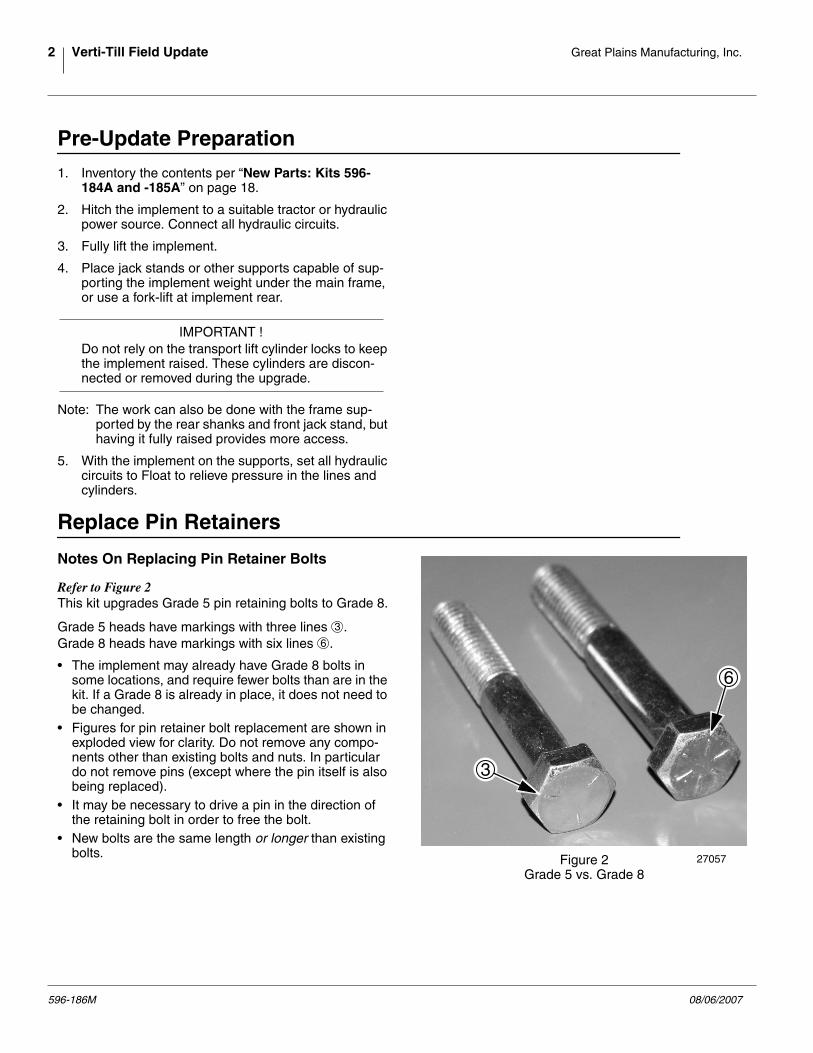
Refer to Figure 2This kit upgrades Grade 5 pin retaining bolts to Grade 8.
Grade 5 heads have markings with three lines .Grade 8 heads have markings with six lines .
• The implement may already have Grade 8 bolts insome locations, and require fewer bolts than are in thekit. If a Grade 8 is already in place, it does not need tobe changed.
• Figures for pin retainer bolt replacement are shown inexploded view for clarity. Do not remove any compo-nents other than existing bolts and nuts. In particulardo not remove pins (except where the pin itself is alsobeing replaced).
• It may be necessary to drive a pin in the direction ofthe retaining bolt in order to free the bolt.
• New bolts are the same length or longer than existingbolts. Figure 2
Grade 5 vs. Grade 827057
3
6
3
6
596-186M 08/06/2007
Great Plains Manufacturing, Inc. Replace Pin Retainers 3
Hitch Toggle Pin Retainers
Refer to Figure 3Replace the retaining bolts and nuts of the pins at eachend of the hitch toggle between the tongue and frame.
6. Remove two sets of existing: HHCS 3/8-16X2 1/4 GR5 NUT LOCK 3/8-16 PLT
These parts are not re-used.
7. Select two sets of new: 802-848C HHCS 3/8-16X2 3/4 GR8 803-013C NUT LOCK 3/8-16 PLT
Install the bolts in the pins.
Tongue Pivot Pin Retainers
Refer to Figure 4Replace the retaining bolts and nuts of the pins at eachof two pivots (left and right side) between the tongueand frame.
8. Remove two sets of existing: HHCS 3/8-16X2 1/2 GR5 NUT LOCK 3/8-16 PLT
These parts are not re-used.
9. Select two sets of new: 802-849C HHCS 3/8-16X3 1/4 GR8 803-013C NUT LOCK 3/8-16 PLT
Install the bolts in the pins.
U
DF
B
L
R
Figure 3Hitch Toggle
21556
55
54
38
35
54 35
55 38
1
Inspect bolt heads before replacing.If already grade 8, skip to next implement location.
1
54
55
35
38
U
DF
B
L
R
Figure 4Tongue-Frame Pivot
21556
52 36
55 38
2
Inspect bolt heads before replacing.If already grade 8, skip to next implement location.
2
52
55
36
38
08/06/2007 596-186M
4 Verti-Till Field Update Great Plains Manufacturing, Inc.
Frame-Rockshaft Pin Retainers
Refer to Figure 5 (showing three of four pins on right side)Replace the retaining bolts and nuts of the two upperpins at each of four pivots , between the frame andcoulter rockshafts. The lower pins are replaced at a laterstep.
Refer to Figure 6 (showing only right side pins)Replace the retaining bolts and nuts of the pins at eachof four pivots (2 left and 2 right side) between the coultersub-frame and level link rockshafts.
12. Remove two sets of existing: HHCS 3/8-16X2 1/2 GR5 NUT LOCK 3/8-16 PLT
These parts are not re-used.
13. Select two sets of new: 802-849C HHCS 3/8-16X3 1/4 GR8 803-013C NUT LOCK 3/8-16 PLT
Install the bolts in the pins.
U
DF
B
L
R
Figure 5Coulter Rockshaft Pivots
21557
52 36
55 383
4
52 36
52 36
55 38
55 38
Inspect bolt heads before replacing.If already grade 8, skip to next implement location.
3 4
52
55
36
38
U
DB
F
R
L
Figure 6Coulter Sub-frame Pivots
21571
52 36
55 38 5
52 36
55 38
Inspect bolt heads before replacing.If already grade 8, skip to next implement location.
5
52
55
36
38
596-186M 08/06/2007
Great Plains Manufacturing, Inc. Replace Pin Retainers 5
Level Link Crank Pin Retainers
Refer to Figure 7 and Figure 8Replace the retaining bolts and nuts of the upper fourpins in each of two triangular cranks , between theframe and transport wheel rockshaft (not shown).
Note: The bolts in the lower end of the vertical links arereplaced on the next page.
Upper and Lower Link Pivots
14. Remove four sets of existing: HHCS 3/8-16X2 1/2 GR5 NUT LOCK 3/8-16 PLT
These parts are not re-used.
15. Select four sets of new: 802-849C HHCS 3/8-16X3 1/4 GR8 803-013C NUT LOCK 3/8-16 PLT
Install the bolts in the pins.
Crank to Frame Pivots
Refer to Figure 8Replace the retaining bolts and nuts of the main pivotpins in each of the two triangular cranks between theframe and transport wheel rockshaft (not shown).
Upper and Lower Link Pivots
16. Remove two sets of existing: HHCS 3/8-16X3 1/4 GR5 NUT LOCK 3/8-16 PLT
These parts are not re-used.
17. Select two sets of new: 802-781C HHCS 3/8-16X3 1/2 GR8 PLT 803-013C NUT LOCK 3/8-16 PLT
Install the bolts in the pins.
U
DF
B
L
R
Figure 7Level Link Crank Links
21558
55 38
52 36
52 36
55 38
52 36
55 38
55 38
5236
5 75 7
Inspect bolt heads before replacing.If already grade 8, skip to next implement location.
52
55
36
38
U
DF
B
L
R
Figure 8Level Link Crank Pivot
21558
53 34
55 38
55 38
5334
Inspect bolt heads before replacing.If already grade 8, skip to next implement location.
53
55
34
38
08/06/2007 596-186M
6 Verti-Till Field Update Great Plains Manufacturing, Inc.
Rockshaft Arm Pin Retainers
Refer to Figure 9 and Figure 10 (showing right side only)Replace the retaining bolts and nuts of the four pins ineach of two floating axle arms .
Lower Vertical Link Pins
These smaller, forward pins connect the arms to the tri-angular crank (not shown).
18. Remove two sets of existing: HHCS 3/8-16X2 1/2 GR5 NUT LOCK 3/8-16 PLT
These parts are not re-used.
19. Select two sets of new: 802-849C HHCS 3/8-16X3 1/4 GR8 803-013C NUT LOCK 3/8-16 PLT
Install the bolts in the pins.
Main Arm Pivot Pins
Refer to Figure 10 (showing right side only)These larger, aft pins connect the arm to the frame.
20. Remove two sets of existing: HHCS 3/8-16X3 1/4 GR5 NUT LOCK 3/8-16 PLT
These parts are not re-used.
21. Select two sets of new: 802-850C HHCS 3/8-16X4 GR8 803-013C NUT LOCK 3/8-16 PLT
Install the bolts in the pins.
U
DF
B
L
R
Figure 9Rockshaft to Frame - Link
21559
52 36
55 368
8
Inspect bolt heads before replacing.If already grade 8, skip to next implement location.
52
55
36
38
U
DF
B
L
R
Figure 10Rockshaft to Frame - Pivot
21559
55 38
8
53 37
Inspect bolt heads before replacing.If already grade 8, skip to next implement location.
8
53
55
37
38
596-186M 08/06/2007
Great Plains Manufacturing, Inc. Replace Pin Retainers 7
Coulter Gang Pin Retainers
Refer to Figure 11 (showing right end only)Replace the retaining bolts and nuts of the 16 pins ineach of eight arms connecting the coulter gangs to thecoulter sub-frame.
Coulter Gang Pivot Pins
These larger, forward/lower pins connect the arms to thesub-frame.
22. Remove two sets of existing: HHCS 3/8-16X2 1/2 GR5 NUT LOCK 3/8-16 PLT
These parts are not re-used.
23. Select two sets of new: 802-849C HHCS 3/8-16X3 1/4 GR8 803-013C NUT LOCK 3/8-16 PLT
Install the bolts in the pins.
Coulter Trunnion Pins
Refer to Figure 12These smaller, aft/upper pins anchor the spring trun-nions to the sub-frame.
24. Remove two sets of existing: HHCS 3/8-16X2 1/4 GR5 NUT LOCK 3/8-16 PLT
These parts are not re-used.
25. Select two sets of new: 802-848C HHCS 3/8-16X2 3/4 GR8 803-013C NUT LOCK 3/8-16 PLT
Install the bolts in the pins.
U
DB
F
R
L
Figure 11Coulter Gang Pivot
21572
52 36
55 38
Inspect bolt heads before replacing.If already grade 8, skip to next implement location.
52
55
36
38
Figure 12Coulter Trunnion Pin
21572
54 35
55 38U
DB
F
R
L
Inspect bolt heads before replacing.If already grade 8, skip to next implement location.
54
55
35
38
08/06/2007 596-186M
8 Verti-Till Field Update Great Plains Manufacturing, Inc.
Transport Lift Cylinder Pins: SN1063+If the implement is serial number 1062 or lower, skip to“Update Lift Cylinders” on page 8. The upper pins areentirely replaced when the cylinder is replaced.
Refer to Figure 13Do not remove the pin .
26. Remove four sets of existing: HHCS 3/8-16X2 1/2 GR5 NUT LOCK 3/8-16 PLT
These parts are not re-used.
27. Select four sets of new: 802-849C HHCS 3/8-16X3 1/4 GR8 803-013C NUT LOCK 3/8-16 PLT
Install the bolts in the pins.
Update Lift Cylinders
Disconnect Transport Rod End
Refer to Figure 14The rod ends of these cylinders are disconnected toupgrade the pinning method. They are also upgradedlater with a clevis replacement or complete cylinderreplacement.
Starting with the left arm:
28. Remove the existing: PIN COTTER 3/16 X 2, WASHER FLAT 1 SAE (may be 0 or 2), and; PIN CLEVIS 1 X 3 3/16 LG.
These parts are not re-used.
29. Repeat step 28 for the right arm.
30. Activate the tractor hydraulics and retract the trans-port lift cylinders. Set circuit to Float to relieve pres-sure.
Figure 13Left Lift Cylinder, Upper Pin
27046
1
5236
55 38U
DB
F
R
L
Inspect bolt heads before replacing.If already grade 8, skip to next implement location.
1
52
55
36
38
Figure 14Left Lift Cylinder, Lower
27046
1
58
56
5756
U
DF
B
L
R
57
56
58
596-186M 08/06/2007
Great Plains Manufacturing, Inc. Update Lift Cylinders 9
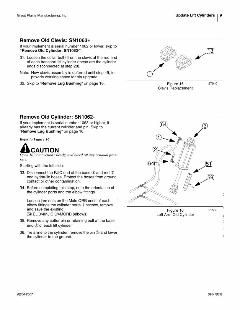
Remove Old Clevis: SN1063+If your implement is serial number 1062 or lower, skip to“Remove Old Cylinder: SN1062-”.
31. Loosen the collar bolt on the clevis at the rod endof each transport lift cylinder (these are the cylinderends disconnected at step 28).
Note: New clevis assembly is deferred until step 49, toprovide working space for pin upgrade.
32. Skip to “Remove Lug Bushing” on page 10.
Remove Old Cylinder: SN1062-If your implement is serial number 1063 or higher, italready has the current cylinder and pin. Skip to“Remove Lug Bushing” on page 10.
Refer to Figure 16
! CAUTIONOpen JIC connections slowly, and bleed off any residual pres-sure.
Starting with the left side:
33. Disconnect the FJIC end of the base and rodend hydraulic hoses. Protect the hoses from groundcontact or other contamination.
34. Before completing this step, note the orientation ofthe cylinder ports and the elbow fittings.
Loosen jam nuts on the Male ORB ends of eachelbow fittings the cylinder ports. Unscrew, removeand save the existing:
EL 3/4MJIC 3/4MORB (elbows)
35. Remove any cotter pin or retaining bolt at the baseend of each lift cylinder.
36. Tie a line to the cylinder, remove the pin and lowerthe cylinder to the ground.
Figure 15Clevis Replacement
27040
1
131
Figure 16Left Arm Old Cylinder
21553
364
2
1
64 51
591 2
64
3
3
08/06/2007 596-186M
10 Verti-Till Field Update Great Plains Manufacturing, Inc.
Remove Lug Bushing
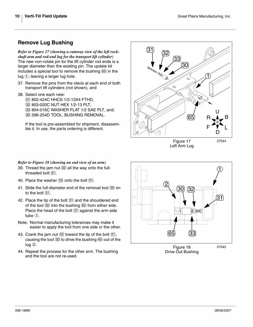
Refer to Figure 17 (showing a cutaway view of the left rock-shaft arm and rod-end lug for the transport lift cylinder)The new non-rotate pin for the lift cylinder rod ends is alarger diameter than the existing pin. The update kitincludes a special tool to remove the bushing in thelug , leaving a larger lug hole.
37. Remove the pins from the clevis at each end of bothtransport lift cylinders (not shown), and
If the tool is pre-assembled for shipment, disassem-ble it. In use, the parts ordering is different.
Refer to Figure 18 (showing an end view of an arm)39. Thread the jam nut all the way onto the full-
threaded bolt .
40. Place the washer onto the bolt .
41. Slide the full-diameter end of the removal tool onto the bolt .
42. Place the tip of the bolt and the shouldered endof the tool into the bushing from either side.Place the head of the bolt against the arm sidetube .
Note: Normal manufacturing tolerances may make iteasier to apply the tool from one side or the other.
43. Crank the jam nut toward the tip of the bolt ,causing the tool to drive the bushing out of thelug .
44. Repeat the process for the other arm. The bushingand the tool are not re-used.
U
DF
B
L
R
Figure 17Left Arm Lug
27044
1
65
3033
3231
65
1
31
32
33
30
Figure 18Drive Out Bushing
27045
1
30
33
32
31
65
2
32
31
33 31
30
31
31
30 65
31
1
32 31
30 65
2
596-186M 08/06/2007
Great Plains Manufacturing, Inc. Update Lift Cylinders 11
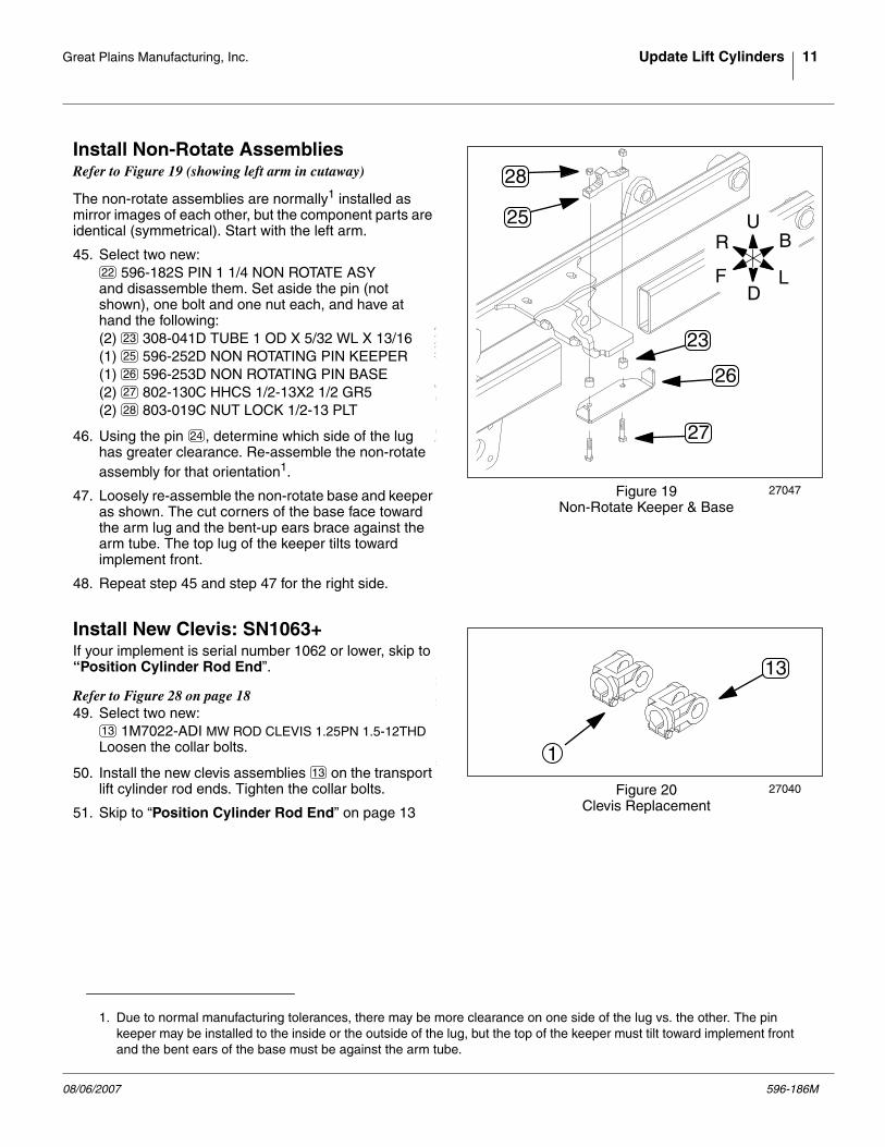
Install Non-Rotate AssembliesRefer to Figure 19 (showing left arm in cutaway)
The non-rotate assemblies are normally1 installed asmirror images of each other, but the component parts areidentical (symmetrical). Start with the left arm.
45. Select two new: 596-182S PIN 1 1/4 NON ROTATE ASY
and disassemble them. Set aside the pin (notshown), one bolt and one nut each, and have athand the following:(2) 308-041D TUBE 1 OD X 5/32 WL X 13/16(1) 596-252D NON ROTATING PIN KEEPER(1) 596-253D NON ROTATING PIN BASE(2) 802-130C HHCS 1/2-13X2 1/2 GR5(2) 803-019C NUT LOCK 1/2-13 PLT
46. Using the pin , determine which side of the lughas greater clearance. Re-assemble the non-rotateassembly for that orientation1.
47. Loosely re-assemble the non-rotate base and keeperas shown. The cut corners of the base face towardthe arm lug and the bent-up ears brace against thearm tube. The top lug of the keeper tilts towardimplement front.
48. Repeat step 45 and step 47 for the right side.
Install New Clevis: SN1063+If your implement is serial number 1062 or lower, skip to“Position Cylinder Rod End”.
Refer to Figure 28 on page 1849. Select two new:
1M7022-ADI MW ROD CLEVIS 1.25PN 1.5-12THDLoosen the collar bolts.
50. Install the new clevis assemblies on the transportlift cylinder rod ends. Tighten the collar bolts.
51. Skip to “Position Cylinder Rod End” on page 13
1. Due to normal manufacturing tolerances, there may be more clearance on one side of the lug vs. the other. The pinkeeper may be installed to the inside or the outside of the lug, but the top of the keeper must tilt toward implement frontand the bent ears of the base must be against the arm tube.
Figure 19Non-Rotate Keeper & Base
27047
28
25
23
27
26
U
DF
B
L
R
22
23
25
26
27
28
24
Figure 20Clevis Replacement
27040
1
13
13
13
08/06/2007 596-186M
12 Verti-Till Field Update Great Plains Manufacturing, Inc.
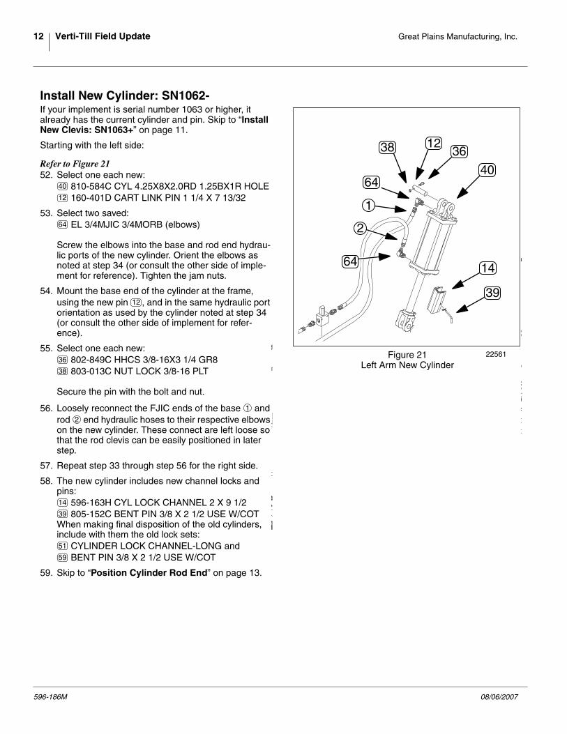
Install New Cylinder: SN1062-If your implement is serial number 1063 or higher, italready has the current cylinder and pin. Skip to “InstallNew Clevis: SN1063+” on page 11.
Starting with the left side:
Refer to Figure 2152. Select one each new:
810-584C CYL 4.25X8X2.0RD 1.25BX1R HOLE 160-401D CART LINK PIN 1 1/4 X 7 13/32
53. Select two saved: EL 3/4MJIC 3/4MORB (elbows)
Screw the elbows into the base and rod end hydrau-lic ports of the new cylinder. Orient the elbows asnoted at step 34 (or consult the other side of imple-ment for reference). Tighten the jam nuts.
54. Mount the base end of the cylinder at the frame,using the new pin , and in the same hydraulic portorientation as used by the cylinder noted at step 34(or consult the other side of implement for refer-ence).
55. Select one each new: 802-849C HHCS 3/8-16X3 1/4 GR8 803-013C NUT LOCK 3/8-16 PLT
Secure the pin with the bolt and nut.
56. Loosely reconnect the FJIC ends of the base androd end hydraulic hoses to their respective elbowson the new cylinder. These connect are left loose sothat the rod clevis can be easily positioned in laterstep.
57. Repeat step 33 through step 56 for the right side.
58. The new cylinder includes new channel locks andpins:
596-163H CYL LOCK CHANNEL 2 X 9 1/2 805-152C BENT PIN 3/8 X 2 1/2 USE W/COT
When making final disposition of the old cylinders,include with them the old lock sets:
CYLINDER LOCK CHANNEL-LONG and BENT PIN 3/8 X 2 1/2 USE W/COT
59. Skip to “Position Cylinder Rod End” on page 13.
Figure 21Left Arm New Cylinder
22561
12
2
1
64
64
36
14
38
40
39
40
12
64
12
36
38
1
2
14
39
51
59
596-186M 08/06/2007
Great Plains Manufacturing, Inc. Update Lift Cylinders 13
Position Cylinder Rod EndStart with the left side.
Refer to Figure 2260. Rotate the cylinder clevis to that the collar bolt is
on top.
61. Extend the clevis onto the arm lug .
Refer to Figure 2362. Select one each set-aside:
596-251D PIN 1 1/4 X 3.94 NON ROT 802-130C HHCS 1/2-13X2 1/2 GR5 803-019C NUT LOCK 1/2-13 PLT
63. Back the clevis off the lug.
64. From the side of the lug opposite the pin keeperassembly, insert the half-round end of the non-rotatepin into the cylinder clevis.
65. Extend the clevis onto the arm lug once more, andinsert the non-rotate pin through the lug, aligning theflat face of the pin with the forward face of the keeperlug.
66. Secure the pin with a bolt and nut. Insert the boltfrom the front.
A complete non-rotate assembly , without clevisand lug, is shown for reference.
67. If the cylinder rod is sufficiently extended, select oneeach:
596-163H CYL LOCK CHANNEL 2 X 9 1/2 805-152C BENT PIN 3/8 X 2 1/2 USE W/COT
and install the lock on the cylinder.
68. Tighten the JIC fittings on the cylinder base ends.Leave the rod ends loose for later bleeding.
69. Repeat step 60 through step 68 for the right side ofthe implement.
Figure 22Cylinder Rod End to Lug
27053
12
1
2
Figure 23Install Non-Rotate Pin
27054
27
28
22
24
24
27
28
24
22
14
39
08/06/2007 596-186M
14 Verti-Till Field Update Great Plains Manufacturing, Inc.
Install Relief Valve
Assemble Valve
Refer to Figure 2470. Select one new:
810-348C RELIEF VALVE 1500 PSI TAMP PRFone new:
811-216C EL 3/4MJIC 9/16MORBand two new:
811-584C AD 9/16MORB 3/4MJIC
71. Screw the Male O-Ring Bushing (MORB) ends of theadaptors into the side ports of the valve.
72. Screw the MORB end of the elbow into the bot-tom/center port of the valve and seat the jam nut.
Open CircuitThe relief valve is plumbed into the transport lift circuit onthe right side of the mainframe, near the right lift cylinder.
! CAUTIONOpen lines first at JIC connectors, and do so slowly, in casethere is any residual pressure in the lines.
Refer to Figure 25Typical implements may vary from the figure, both inhose and clamp placement.
73. Trace the hoses and ensure that you understandwhich is rod (lower/retract) and which is base (lift/extend). Usually, the rod circuit is the upper hose ,and the base circuit is the lower hose .
74. Loosen any clamps necessary to free hoses for dis-connection and routing adjustments.
75. Crack the hose JIC connectors , just forward ofthe tees and bleed off any residual pressure.Unscrew the JIC connectors completely.
Figure 24Assemble Relief Valve
27041
16
19
18
19
16
18
19
19
18
Figure 25Open Circuit
27042
1
2
U
DF
B
L
R
1
2
1 2
596-186M 08/06/2007
Great Plains Manufacturing, Inc. Install Relief Valve 15
Install Valve Fittings
Refer to Figure 2676. Select one new:
811-073C TE 3/4MJIC 3/4MJIC 3/4FJIC
Connect the F-JIC end of the new tee to the M-JIC end of the existing base circuit tee . Orient thecenter M-JIC port of the tee pointing away from theframe.
77. Connect the base circuit hose to the new tee .
78. Select one new: 841-209C HH1/2R1 008 3/4FJIC (8in hose)
Connect one end of the new hose to the M-JICend of the existing rod circuit tee .
79. Select one new: 841-008C HH3/8R2 017 3/4FJIC (17in hose)
Connect one end of the new hose to the centerport of the new tee .
Figure 26Valve Fittings
27043
1
2
17
3
214
20To Tr
actor LOWER
To Tractor RAISE
To Rod End
To Base End
To R
od E
nd
To B
ase E
nd
17
17
3
2 17
21
21
4
20
20
17
08/06/2007 596-186M
16 Verti-Till Field Update Great Plains Manufacturing, Inc.
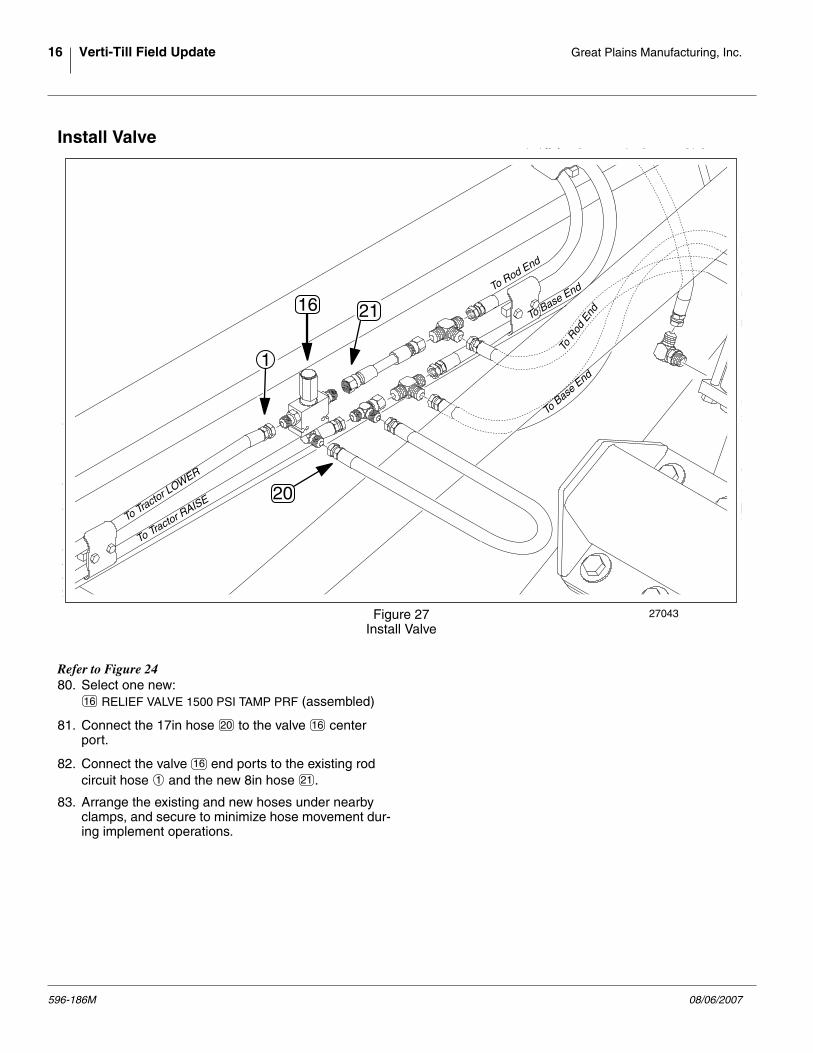
Install Valve
Refer to Figure 2480. Select one new:
RELIEF VALVE 1500 PSI TAMP PRF (assembled)
81. Connect the 17in hose to the valve centerport.
82. Connect the valve end ports to the existing rodcircuit hose and the new 8in hose .
83. Arrange the existing and new hoses under nearbyclamps, and secure to minimize hose movement dur-ing implement operations.
Figure 27Install Valve
27043
1
20
2116
To Tractor L
OWER
To Tractor RAISE
To Rod End
To Base End
To R
od E
nd
To B
ase E
nd
16
20 16
16
1 21
596-186M 08/06/2007
Great Plains Manufacturing, Inc. Closeout 17
Closeout
Refer to Verti-Till Operator’s manual.84. Connect the Transport and Coulter lift circuits to the
tractor.
85. If the transport lift locks are not installed, carefullyextend the transport lift circuit to raise the implementenough to install the locks.
86. Conduct the “Bleeding Transport Cylinders” proce-dure from the Operator’s manual.
87. Check all hydraulic fittings for leaks.
88. Extend the Transport lift circuit and install the locks.
89. Lower the fork lift or dismount the implement fromthe blocks or stands used to hold it up.
90. Remove the locks from Transport lift cylinders, andexercise both lift circuits, checking for binding ormissing bolts at all hinge points.
91. Raise both circuits and install locks.
08/06/2007 596-186M
18 Verti-Till Field Update Great Plains Manufacturing, Inc.
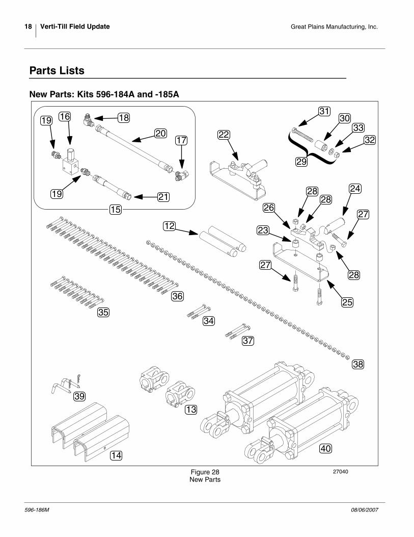
Parts Lists
New Parts: Kits 596-184A and -185A
Figure 28New Parts
27040
22
3130
3332
29
2828
28
25
27
27
24
23
26
12
1720
1819 16
19 2115
36
34
37
35
38
39
14
13
40
{
596-186M 08/06/2007
Great Plains Manufacturing, Inc. Parts Lists 19
Your kit includes the parts listed below. Each kit containsonly some of the parts illustrated on page 18.
The part call-out numbers in this list match all Figures inthe installation instructions.
Quantity in Kit 596-
Callout -184A -185A Part Number Part Description
1 1 596-186M This manual (not shown above)
2 0 160-401D CART LINK PIN 1 1/4 X 7 13/32
0 2 1M7022-ADI MW ROD CLEVIS 1.25PN 1.5-12THD
2 0 596-163H CYL LOCK CHANNEL 2 X 9 1/2
1 1 596-181V RELIEF VALVE KIT
1 1 810-348C RELIEF VALVE 1500 PSI TAMP PRF
1 1 811-073C TE 3/4MJIC 3/4MJIC 3/4FJIC
1 1 811-216C EL 3/4MJIC 9/16MORB
2 2 811-584C AD 9/16MORB 3/4MJIC
1 1 841-008C HH3/8R2 017 3/4FJIC
1 1 841-209C HH1/2R1 008 3/4FJIC
2 2 596-182S PIN 1 1/4 NON ROTATE ASY
4 4 308-041D TUBE 1 OD X 5/32 WL X 13/16
2 2 596-251D PIN 1 1/4 X 3.94 NON ROT
2 2 596-252D NON ROTATING PIN KEEPER
2 2 596-253D NON ROTATING PIN BASE
6 6 802-130C HHCS 1/2-13X2 1/2 GR5
6 6 803-019C NUT LOCK 1/2-13 PLT
1 1 - ASSY, BUSHING REMOVAL TOOL
1 1 596-254D TOOL, BUSHING REMOVAL
1 1 802-424C HHCS 1/2-13X4 FTHD
1 1 803-020C NUT HEX 1/2-13 PLT
1 1 804-016C WASHER FLAT 1/2 SAE PLT
2 2 802-781C HHCS 3/8-16X3 1/2 GR8 PLT
10 2 802-848C HHCS 3/8-16X2 3/4 GR8
30 18 802-849C HHCS 3/8-16X3 1/4 GR8
2 2 802-850C HHCS 3/8-16X4 GR8
46 20 803-013C NUT LOCK 3/8-16 PLT
2 0 805-152C BENT PIN 3/8 X 2 1/2 USE W/COT
2 0 810-584C CYL 4.25X8X2.0RD 1.25BX1R HOLE
11
12
13
14
15
16
17
18
19
20
21
22
23
24
25
26
27
28
29
30
31
32
33
34
35
36
37
38
39
40
08/06/2007 596-186M
20 Verti-Till Field Update Great Plains Manufacturing, Inc.
Existing Parts AffectedThe following existing parts may be involved in the kitinstallation. The Disposition column indicates whetherparts are left in place, moved or not re-used.
The part call-out numbers in the list match all Figures inthe installation instructions. Descriptions match those inyour implement Parts manual.
Existing Parts ListCallout Part No. Part Description Part Disposition
161-073H CYLINDER LOCK CHANNEL-LONG Removed. Not re-used.
802-114C HHCS 3/8-16X2 1/2 GR5 Removed. Not re-used.
802-168C HHCS 3/8-16X3 1/4 GR5 Removed. Not re-used.
802-382C HHCS 3/8-16X2 1/4 GR5 Removed. Not re-used.
803-013C NUT LOCK 3/8-16 PLT Removed. Not re-used.
804-029C WASHER FLAT 1 SAE Removed. Not re-used.
805-058C PIN COTTER 3/16 X 2 Removed. Not re-used.
805-090C PIN CLEVIS 1 X 3 3/16 LG Removed. Not re-used.
805-152C BENT PIN 3/8 X 2 1/2 USE W/COT Removed. Not re-used.
- Transport Lift Cylinder <depends on implement serial number>
810-516C CYL 4X8X1.5 ROD HARDENED BUSH Removed. Not re-used.
810-536C CYL 4X8X1.5 ROD 1 1/4BX1R HOLE Removed. Not re-used.
810-584C CYL 4.25X8X2.0RD 1.25BX1R HOLE Removed and re-installed.
811-063C EL 3/4MJIC 3/4MORB Removed and re-installed.
890-005C BUSHING CYL 1 1/4 X 1 X 1 Removed. Not re-used.
51
52
53
54
55
56
57
58
59
60
61
62
63
64
65
596-186M 08/06/2007
Great Plains Manufacturing, Inc. Reference Information 21
Reference Information
Abbreviations Connector Identification
➀ JIC - Joint Industry Conference (SAE J514)Note straight threads ➁ and the37° cone ➂ on “M” fittings (or 37° flare on “F”).
➃ ORB - O-Ring Boss (SAE J514)Note the straight threads ➄ and,elastomer O-Ring ➅.Fittings needing orientation, such as the ell above,also have a washer ➆ andjam nut ➇ (“adjustable thread port stud”)
Torque Values
AD Adaptor
ADI Austempered Ductile Iron
ASY Assembly
COT Cotter pin
CYL Cylinder
EL Elbow
FTHD Full-Threaded
GR Grade
HHCS Hex Head Cap Screw (Bolt)
LH Left Hand
JIC Joint Industry Conference (Male &Female)
MW Midway (supplier name)
ORB O-Ring Bushing (Male & Female)
OD Outside Diameter
PLT Plated
PN Pin (diameter)
PSI Pounds per Square Inch
RH Right Hand
RHSNB Round Head Shank Neck Bolt
SAE Society of Automotive Engineers(mechanical standard)
TAMP PRF Tamper-Proof
TE Tee
THD Thread
Fastener/Fitting Ft-Lbs N-m
3⁄8-16 Grade 8 31 42
1⁄2-13 Grade 5 105 76
9⁄16 ORB jam nut 12-16 16-22
9⁄16 ORB straight 18-24 24-32
3⁄4 JIC 27-39 37-53
➀
➁➂
➃
➄➅
➆➇
25188
08/06/2007 596-186M
EOD
Great Plains Manufacturing, Inc.Corporate Office: P.O. Box 5060Salina, Kansas 67402-5060 USA