12
Vertical Machining Center VX-1000

Vertical Machining Center
VX-1000

2
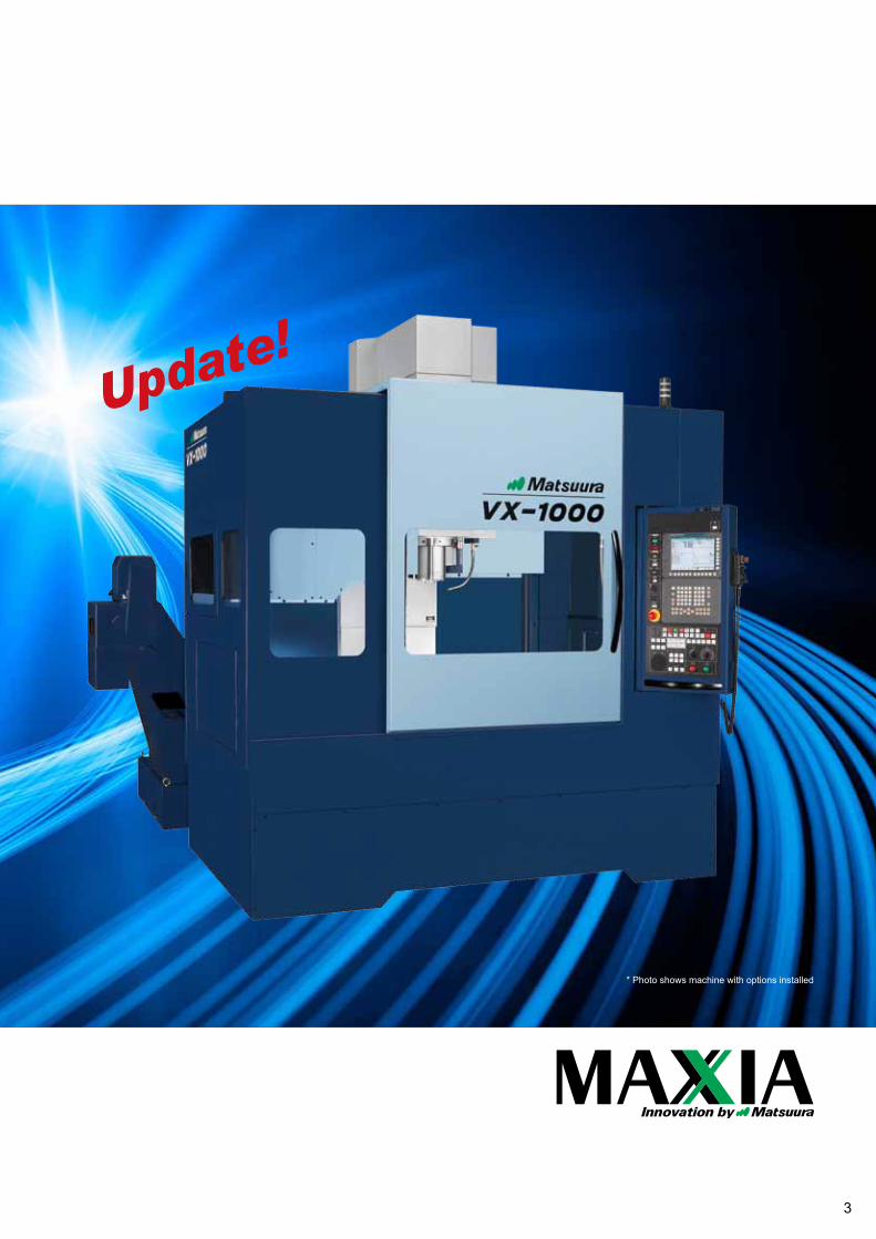
VX-1000
Introducing the VX Series: Cost EffectiveHeavy Duty PerformanceBetter by Design; The Upgraded VX-1000, with new Fanuc 31i control,modernized ergonomic guarding & increased versatility & functionality.
Coolant-through mechanism Lift-up conveyor
Y:610mm(24.01 in.)
Z:610mm(24.01 in.)
X:1,020mm(40.15 in.)
Table size: 1,200×600 mm (47.24×23.62 in.)
Loading Capacity: 500 kg (1,100 lb.) spindle: 15,000 min-1
Standard features: Spindle through coolant and lift up conveyor.
3
* Photo shows machine with options installed
Update!
4
Torque(N・m)
Power(kW)
150000.1
1
10
50
5000
2500 3700 100001000 140010050
500
100
10
110
15.0kW11.0kW
7.5kW
0.79kW0.66kW0.54kW
9.55N・m7.00N・m4.78N・m
150.0N・m126.2N・m
15-minute rating
30-minute rating
Continuous rating
102.2N・m102.2N・m
18.518.513.713.715.015.0
18.518.522.022.0
11.111.1
16.416.4
42.042.035.335.3
28.628.6
16.322.0
15.0
21.831.042.3
8.4
12.012.0
Spindle speed (min-1)
0.1
1
10
50
4500 6000 20000132050
500
100
10
110
0.45kW
15.0kW
0.33kW
29.4N・m
23.9N・m
79.5N・m79.5N・m
108.4N・m108.4N・m
8.8N・m8.8N・m
11.0kW11.0kW15kW15kW
18.5kW18.5kW
7.2N・m7.2N・m
Power(kW)
Torque(N・m)
Spindle speed (min-1)
50% rating
Continuous rating
BT40 15,000 min-1Standard
BT40 20,000 min-1Option
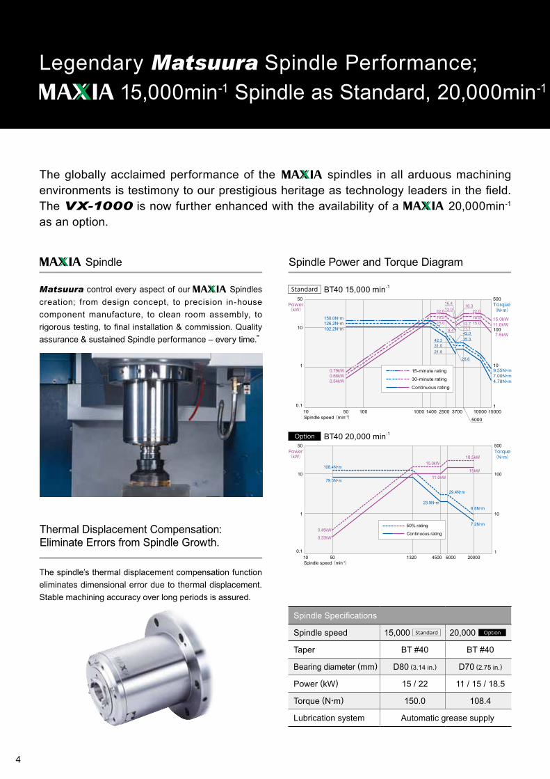
Legendary Matsuura Spindle Performance; 15,000min-1 Spindle as Standard, 20,000min-1 Option
Thermal Displacement Compensation:Eliminate Errors from Spindle Growth.
Spindle Power and Torque Diagram
The spindle’s thermal displacement compensation function eliminates dimensional error due to thermal displacement. Stable machining accuracy over long periods is assured.
The globally acclaimed performance of the spindles in all arduous machining environments is testimony to our prestigious heritage as technology leaders in the field. The VX-1000 is now further enhanced with the availability of a 20,000min-1 as an option.
Spindle Specifications
Spindle speed 15,000 20,000
Taper BT #40 BT #40
Bearing diameter (mm) D80 (3.14 in.) D70 (2.75 in.)
Power (kW) 15 / 22 11 / 15 / 18.5
Torque (N・m) 150.0 108.4
Lubrication system Automatic grease supply
Spindle
Matsuura control every aspect of our Spindles creation; from design concept, to precision in-house component manufacture, to clean room assembly, to rigorous testing, to final installation & commission. Quality assurance & sustained Spindle performance – every time.”
Standard Option
5
■ Cutting test results (in.)
Work material Tool Cut width
Cut depthSpindle
rotation speedCutting
feed rateCutting amount
Work material Tool Spindle
rotation speedCutting
feed rateWork
material
AluminumØ80mm
(3.14)3 blades
W=70mm(2.75)
D=5mm(0.19)
5,500min-1
8,000mm/min(314.96)
2,800cc/min Aluminum Ø35mm
(1.37)1,500min-1
700mm/min(27.55)
673cc/min
SteelØ80mm
(3.14)5 blades
W=70mm(2.75)D=3mm(0.11)
2,800min-1
1,120mm/min(44.09)
588cc/min Steel Ø35mm
(1.37)1,300min-1
330mm/min(12.99)
317cc/min
AluminumØ25mm(0.98)
2 blades
W=22mm(0.86)
D=8.5mm(0.33)
12,000min-1
10,000mm/min(393.70)
1,870cc/min A5052 M36
× P4.0120min-1
480mm/min(18.89)
SteelØ20mm(0.78)
4 blades
W=3mm(0.11)
D=35mm(1.37)
5,500min-1
5,500mm/min(216.53)
578cc/min Steel M30
× P3.5100min-1
350mm/min(13.77)
Face mill Drill
End mill Tap
*Results above may differ in repeat tests due to different operating conditions.
BT40 15,000 min-1Standard
Legendary Matsuura Spindle Performance; 15,000min-1 Spindle as Standard, 20,000min-1 Option
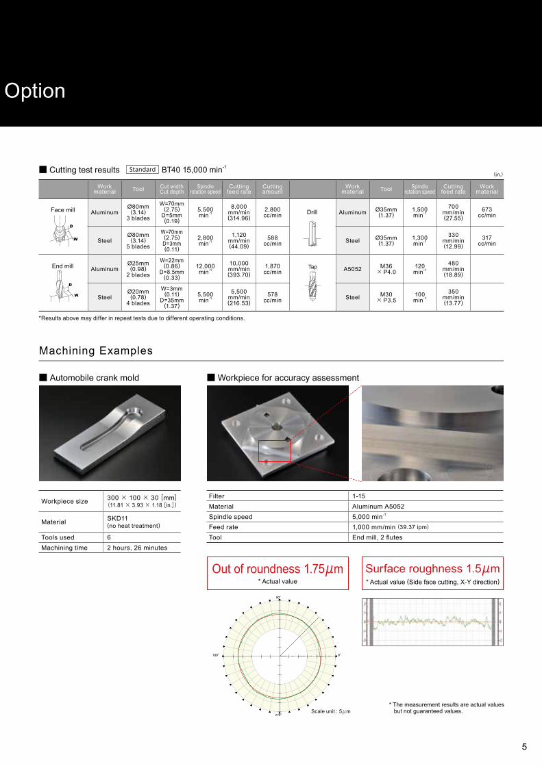
■ Automobile crank mold ■Workpiece for accuracy assessment
Out of roundness 1.75μm* Actual value
Surface roughness 1.5μm * Actual value (Side face cutting, X-Y direction)
* The measurement results are actual values but not guaranteed values.Scale unit : 5μm
Machining Examples
Workpiece size 300 × 100 × 30[mm](11.81 × 3.93 × 1.18[in.])
Material SKD11(no heat treatment)
Tools used 6Machining time 2 hours, 26 minutes
Filter 1-15Material Aluminum A5052Spindle speed 5,000 min-1
Feed rate 1,000 mm/min(39.37 ipm)Tool End mill, 2 flutes

6
Automatic tool changer
Random Memory System” adopted, shortening the waiting time to select the next too.
■ Standard drum magazine for 30 tools
■ Maximum tool size mm(in.)
■ Chain magazine for 48/60 tools Option
φ76
(2.9
9)
φ63
(2.4
8)φ
63 (2
.48)
280 (11.02)
280 (11.02)
50(1.96)
50(1.96)
φ12
5 (4
.92)
〈With adjacent tools〉
〈With no adjacent tools〉
The ATC is equipped with a 30-tool drum magazine as standard.48-tool and 60-tool chain magazines are available as options.
Expanded ATC Capacity; 60 Tool Stations
7
High-precision positioning
High precision and rigidity are standard features of all ballscrews and linear guides - offering dynamic and repeatable performance over many years of operation.
■ Positioning accuracy of each axis
* The measurement results are actual values but not guaranteed values.
0 100 200 300 400 500 600 700 800 900 1000 (mm)
0
-1
-2
1
2
3 (μm) X-Axis
-600 -500 -400 -300 -200 -100 0 (mm)
0
-1
-2
-3
1 (μm) Y-Axis
-600 -500 -400 -300 -200 -100 0 (mm)
0
-1
-2
1
2
3
4 (μm) Z-Axis
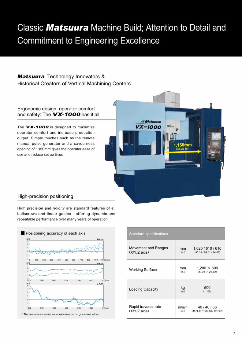
Matsuura; Technology Innovators &Historical Creators of Vertical Machining Centers
Classic Matsuura Machine Build; Attention to Detail andCommitment to Engineering Excellence
Ergonomic design, operator comfort and safety: The VX-1000 has it all.
The VX-1000 is designed to maximise operator comfort and increase production output. Simple touches such as the remote manual pulse generator and a cavourness opening of 1,150mm gives the operator ease of use and reduce set up time.
1,150mm(45.27 in.)
Standard specifications
Movement and Ranges(X/Y/Z axis)
mm(in.)
1,020 / 610 / 610(40.15 / 24.01 / 24.01)
Working Surface mm(in.)
1,200× 600(47.24 × 23.62)
Loading Capacity kg(lb.)
500(1,100)
Rapid traverse rate(X/Y/Z axis)
m/min(in.)
40 / 40 / 36(1574.80 / 1574.80 / 1417.32)

8
Excellent Swarf Management
Modern machine shops and production environments require proven swarf management. Downtime due to blocked conveyors and "swarf traps" because of poor machine design are unacceptable as manufacturers lessen their time to market and improve cost per part ratios. The VX-1000 inherits all of the design success of previous Matsuura machines and their proven swarf management design systems.
■ Lift-up conveyor■ Lift-up conveyor (with drum filter)
■ Coolant-through Spindle System
■ Chip flush■ Spiral chip conveyor■ Air Blow for Chip Removal
■Workpiece cleaning gun
VX-1000; a consummate performer, no matter what the task,no matter what the material
Dedicated & Focussed on Operability,Functionality & Ease of Use
Option

9
Combining craftsmanship, skill and ingenuityMatsuura’s original interface with uncompromising pursuit of utility
Matsuura Intelligent Meister System
Environment Accuracy
Simple
Eco Meister Thermal Meister
■ Power cut-off function ■ Spindle thermal displacement compensation
Power savings Stable accuracy
Operability Meister
■ Tool setup support■ Workpiece setup support■ Restart after machining stop
Hassle-free, simple operation
Selectable M Codes Operation panel
Matsuura original M codes now selectable Operation panel changed for improved operability
Secure
Reliability Meister
■ Preventive maintenance support function■ Machine recovery support function
Reduced machine downtime
Reliability Meister Plus
■ Electronic manual function■ Mail transmission function
Offering greater peace of mind
Function MatsuuraM code
VXM code
Through-spindle coolant start M50 M11
Air blow for chip removal start/stop M25/ 27 M12/ 32
Rigid tap mode preparation M80 M29
4th-axis clamp M21 M43
Orientation start forautomatic measurement M59 M109
Air blow start/stopTool breakage detection sensor M63/ 64 M47/ 48
Automatic measurement ON/OFF M108/ 109 M58/ 85
Operator door open/close M78/ 79 M138/ 139
* Can be changed by parameter.
10
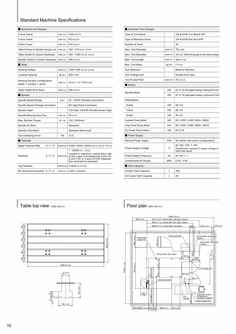
Floor plan Unit: mm (in.)Table top view Unit: mm (in.)
■ Movement and Ranges
X-Axis Travel mm (in.) 1020 (40.15)
Y-Axis Travel mm (in.) 610 (24.01)
Z-Axis Travel mm (in.) 610 (24.01)
Table Surface to Spindle Gauge Line mm (in.) 100 - 710 (3.93 - 27.95)
Table Center to Column Guideway mm (in.) 390 - 1000 (15.35 - 39.37)
Spindle Center to Column Guideway mm (in.) 695 (27.36)
■ Table
Working Surface mm (in.) 1200×600 (47.24×23.62)
Loading Capacity kg (lb.) 500 (1100)
Working Surface Configuration(width× number× pitch) mm (in.) 18 (0.7)×5×100 (3.93)
Table Height (from floor) mm (in.) 930 (36.61)
■ Spindle
Spindle Speed Range min-1 50 - 15000 (Grease Lubrication)
Spindle Speed Change Command S5-digit Direct Command
Spindle Taper 7/24 Taper JIS BT40 (Double Contact Type)
Spindle Bearing Inner Dia. mm (in.) 80 (3.14)
Max. Spindle Torque N・m 150 / 1400min-1
Spindle Air Blow Standard
Spindle Orientation Standard (Electrical)
Tool Clamping Force kN 12.0
■ Feedrate
Rapid Traverse Rate X / Y / Z mm/min (ipm) 40000 / 40000 / 36000 (1574.8 / 1574.8 / 1417.32)
Feedrate X / Y / Z mm/min (ipm)
1 - 20000 (0.1 - 787.4)
Limited to maximum cutting feed rate of the z-axis if simultaneous 2-axis (X/Z and Y/Z) or 3-axis (X/Y/Z) interpola-tion command is executed.
Jog Feedrate mm/min (ipm) 0-4000 (0-157.48)
Min. Movement Increment X / Y / Z mm (in.) 0.001 (0.000039)
■ Automatic Tool Changer
Type of Tool Shank JIS B 6339 Tool Shank 40T
Type of Retention Knob JIS B 6339 Pull Stud 40P
Number of Tools 30
Max. Tool Diameter mm (in.) 76 (2.99)
Max. Tool Diameter mm (in.) 125 (4.92) (When the pockets on both side are empty)
Max. Tool Length mm (in.) 280 (11.02)
Max. Tool Mass kg (lb.) 7 (15.4)
Tool Selection Memory Random
Tool Change Arm Double Grip Type
Tool Pocket Pitch mm (in.) 76.2 (3.0)
■ Motors
Spindle MotorkW AC 15 / 22 (low-speed winding: continuous/15 min)
kW AC 15 / 22 (high-speed winding: continuous/15 min)
Feed Motors
X-Axis kW AC 3.0
Y-Axis kW AC 3.0
Z-Axis kW AC 4.0
Coolant Pump Motor kW AC 0.555 / 0.885 (50Hz / 60Hz)
Chip Flush Pump Motor kW AC 0.555 / 0.885 (50Hz / 60Hz)
Oil Cooler Pump Motor kW AC 0.75
■ Power Supply
Electrical Power Supply kVA 30 (varies with option configuration)
Power Supply Voltage VAC 200 / 220 ± 10%Transformer required if supply voltage is other than above
Power Supply Frequency Hz 50 / 60 ± 1
Compressed Air Supply MPa 0.54 - 0.93
■ Tank Capacity
Coolant Tank Capacity L 300
Oil Cooler Tank Capacity L 36
Standard Machine Specifications
4345
(171
.06)
(880
(34.
64))
2515
(99.
01)
545(
21.4
5)54
5(21
.45)
201 934 (36.77) 518 (20.39)
391
1005 (BED) (39.56)
600
(23.
62)
1618
(BED
) (63
.70)
600
(23.
62)
268 1100 (43.30) (107 (4.21))
5000 (196.85)
2625 (103.34)
900 (35.43)
676
(26.
61)
2833 (111.53)
3211 (126.41)
(40 (1.
57)) (85 (3.34))
(58 (2.28))646
282
Leveling Bolt7-M36×P2
30-tool (#40, drum type)
Operation panel
NC Box
OilCooler
Lift-up conveyor
Power Supply Port
Separate coolanttemperaturecontroller (Option)
Air supply portAir supply port
48-tool (#40, chain type) (Option)48-tool (#40, chain type) (Option)
60-tool (#40, chain type) (Option)60-tool (#40, chain type) (Option)
(60-tool (#40, chain type)) (Option) (48-tool (#40, chain type)) (Option)
(30-tool (#40, drum type)) (10.55) (10.55)
(11.10)
(15.39)
(7.91)
(25.43)(505
(19.
88))
(505
(19.
88))
1200 (47.24)
600
(23.
62)
100
(3.9
3)10
0(3
.93)
100
(3.9
3)10
0(3
.93)
100
(3.9
3)10
0(3
.93)
32 (1
.25)
12 (0.4
7)2
(0.0
7)
30 (1.18)
18+0.027 0

11
1200 (47.24) (table size)
Lift-upconveyor
1020 (40.15) (X-axis travel)
Table (1200×600 (47.24×23.62))
510 (20.07)510 (20.07)
2450 (9
6.45
)2420~3030
(95.
27~
119.
29)
889
(35.
00)
610 (24.01) (Y-axis travel)
(Z-axis travel)
610
(24.
01)
600 (23.62)305 305265
930
(36.
61)
(10.43) (12.00) (12.00)
100
(3.9
3)100
(3.9
3)
External view Unit: mm (in.)
■ Machine Size
Machine Height (from floor) mm (in.) 3030 (119.29)
Required floor space(including maintenance area) mm (in.)
4345W×5000D (171.06W×196.85D) (varies with option configuration)
Mass of Machine kg (lb.) 7390 (16258) (include NC Equipment and ATC Magazine)
■ NC System
Control System
■ Standard Accessories
01. Total Enclosure Guard With Top Side Cover
02. ATC Magazine Guard
03. CE Markings
04. Synchronized Tapping Function
05. Spindle Oil Cooler
06. Lift-up Chip Conveyor (Scraper)
07. Air Blow for Chip Removal
08. Workpiece Cleaning Gun
09. Coolant-through Spindle System
10. Spindle Thermal Displacement Compensation, 15k, BT40, Temperature Monitor Type
11. Chip Flush System
12. Coolant System Chip Side Discharge
13. Auto Oil Supply Unit for Feed Axes Greasing Points with Female Ball Screws (X/Y/Z)
14. Work Light
15. 3-color signal light
16. External Manual Pulse Generator
17. Tools and Tool Box
18. Machine Color Paint
19. MIMS20. AD-TAP funct ion21. IPC funct ion22. Spindle overload protection
23. M code counter (9 types)
24. Spindle runhour meter (within the MIMS screen)
25. Automatic operation runhour meter (within the MIMS screen)
26. Leveling Bolts and Leveling Plates Not for Foundation
27. Memory card program operation and editing CD-ROM
■ Spindle
20,000min-1(BT40 Grease Lubrication)
■ ATC
48 Tools (#40 Chain Magazine)
60 Tools (#40 Chain Magazine)
■ Scale Feedback System
Scale Feedback System X/Y/Z (HEIDENHAIN)
■ Coolant-through Spindle System
Oil Temperature Controller with 50-BAR Coolant-through System of Mono-block Construction
70 bar, supporting through-spindle coolant system
■ Chip Removal
Coolant Temperature Controller with 100-liter Tank (Separately Installed, Small Size)
Lift-up conveyor (with drum filter)
■ Automatic Measurement, Tool Breakage Detection
Automatic Measurement / Automatic Alignment (Optical)
Tool Breakage / Full Automatic Tool Length Measurement (Contact)
Tool Breakage / Full Automatic Tool Length Measurement (Laser)
Automatic Measurement (Optical) / Tool Breakage (Contact)
Automatic Measurement (Optical) / Tool Breakage (Laser)
■ Rotary Wiper
Rotary Wiper
Machine Option
Front view Right side view
* Optional accessories in a wide variety are available in addition to the above. For details, contact your Matsuura representative.
* 2 years spindle warranty
Matsuura G-Tech 31i
*
OE-E1.4 201608 3000 B S
This product is subject to all applicable export control laws and regulations
URL : http://www.matsuura.co.jp/E-MAIL : [email protected]
● Product specifications and dimensions are subject to change without prior notice.● The photos may show optional accessories.
MATSUURA MACHINERY CORPORATION1-1 Urushihara-cho Fukui City 910-8530, JapanTEL : +81-776-56-8106 FAX : +81-776-56-8151
MATSUURA EUROPE GmbHBerta-Cramer-Ring 21D-65205 Wiesbaden-Delkenheim, GermanyTEL : +49-6122-7803-80 FAX : +49-6122-7803-33URL : http://www.matsuura.de/E-MAIL : [email protected]
MATSUURA MACHINERY Ltd.Gee Road, Whitwick Business Park, Coalville Leicestershire, LE67 4NH, EnglandTEL : +44-1530-511-400 FAX : +44-1530-511-440URL : http://www.matsuura.co.uk/E-MAIL : [email protected] : www.facebook.com/pages/Matsuura-Machinery-Ltd/427006380682983
MATSUURA MACHINERY GmbHBerta-Cramer-Ring 21D-65205 Wiesbaden-Delkenheim, GermanyTEL : +49-6122-7803-0 FAX : +49-6122-7803-33URL : http://www.matsuura.de/E-MAIL : [email protected]
ELLIOTT MATSUURA CANADA INC.2120 Buckingham Road Oakville Ontario L6H 5X2, CanadaTEL : +1-905-829-2211 FAX : +1-905-829-5600URL : http://www.elliottmachinery.com/E-MAIL : [email protected]
MATSUURA MACHINERY USA INC.325 Randolph Ave., St.Paul, MN 55102, U.S.A.TEL : +1-651-289-9700URL : http://www.matsuurausa.com/E-MAIL : [email protected]


