30
Vertical Wall Structure Calculations

Vertical Wall Structure Calculations

Hydrodynamic Pressure Distributions on a Vertical Wall (non-breaking waves)
two time-varying components: • the hydrostatic pressure component due to the instantaneous
water depth at the wall (this component is affected by opposing lee-side hydrostatic pressure
• the dynamic pressure component due to the accelerations of the water particles.

Hydrodynamic Pressure Distributions on a Vertical Wall (overtopping)
• Wave overtopping truncates the pressure distribution & reduces the total force and moment
• Possible effects of overtopping on land-based vertical structures due to seaward pressure on the wall caused by saturated backfillor ponding water must be considered.

Types of Wave ForcesNon-breaking waves: • No air pocket against the wall. • Pressure is almost in phase with the
wave elevation. • load treated as a static load in stability
calculations. Breaking waves (vertical fronts): • high pressures with extremely short
durations. • negligible air entrapped, • very large single peaked force followed
by very small force oscillations. Breaking waves (large air pockets):• double peaked force is produced followed
force oscillations • first (largest) peak wave crest hitting
the structure (hammer shock)• second peak compression of the air
pocket • force oscillations are due to the pulsation
of the air pocket.

Basic Pressure Diagram
p3
p1
p2
B
pu
Pressures are due to both the• the hydrostatic pressure component (opposed by the lee-side pressure)• the dynamic pressure component

Hydrostatic Pressure Diagram
FU
seaside lee-side
FS
FL
FU
Lee-sidez > h, p(z) = 0 z ≤ h, p(z) = γ(h – z) η
h + ηh
hz
Seaside:0 ≤ z ≤ h + η
p(z) = γ(h + η – z) ptot(z) = γ(η), z ≤ hptot(z) = γ(h + η – z), z > h
Note: η is the maximum height of wave influence, it includes the wave height & may or may not include a setup component
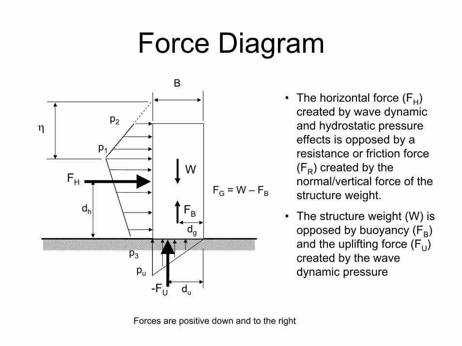
Force Diagram
FH
-FU
W
FB
B
dh
du
p3
p1
pu
FG = W – FB
dg
p2
• The horizontal force (FH) created by wave dynamic and hydrostatic pressure effects is opposed by a resistance or friction force (FR) created by the normal/vertical force of the structure weight.
• The structure weight (W) is opposed by buoyancy (FB) and the uplifting force (FU) created by the wave dynamic pressure
η
Forces are positive down and to the right

Failure Modes:Sliding
Sliding occurs if FH > FR
FH
FR = µFN = µ(W – FB – FU)
Forces are positive down and to the right
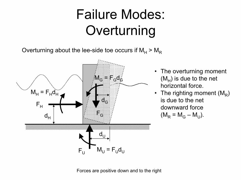
Failure Modes:Overturning
Overturning about the lee-side toe occurs if MH > MR
MH = FHdH
dU
MU = FUdU
FG
dG
MG = FGdG
• The overturning moment (MH) is due to the net horizontal force.
• The righting moment (MR) is due to the net downward force (MR = MG – MU).
FH
dH
FU
Forces are positive down and to the right
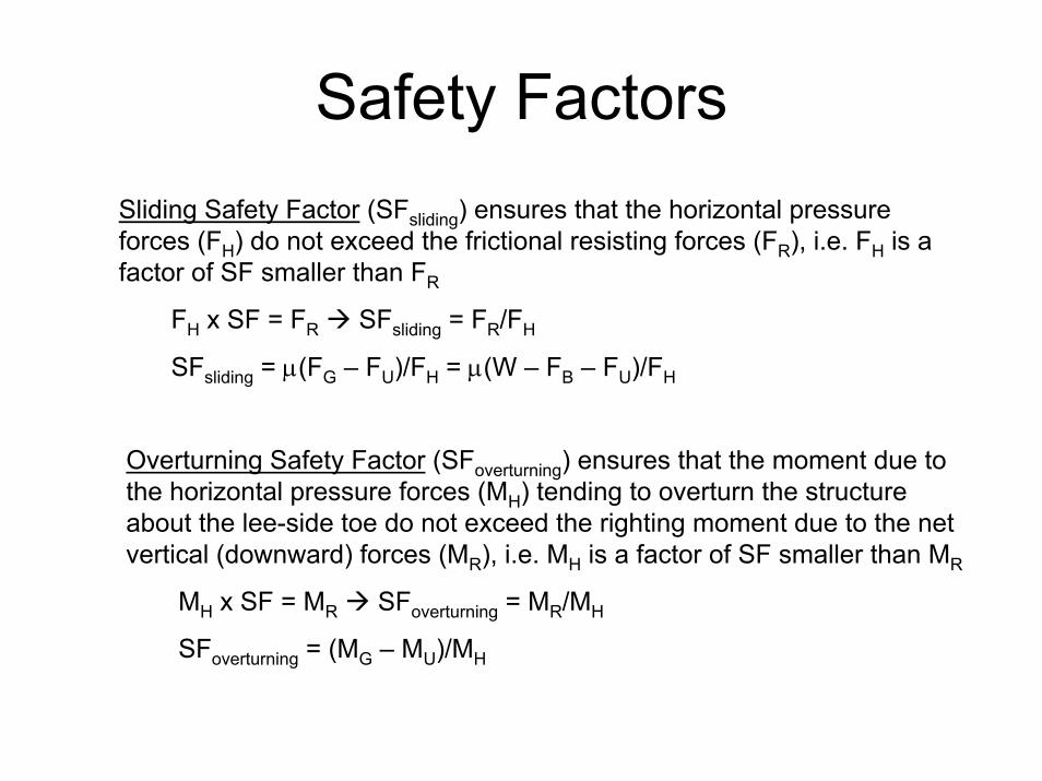
Safety FactorsSliding Safety Factor (SFsliding) ensures that the horizontal pressure forces (FH) do not exceed the frictional resisting forces (FR), i.e. FH is a factor of SF smaller than FR
FH x SF = FR SFsliding = FR/FH
SFsliding = µ(FG – FU)/FH = µ(W – FB – FU)/FH
Overturning Safety Factor (SFoverturning) ensures that the moment due to the horizontal pressure forces (MH) tending to overturn the structure about the lee-side toe do not exceed the righting moment due to the net vertical (downward) forces (MR), i.e. MH is a factor of SF smaller than MR
MH x SF = MR SFoverturning = MR/MH
SFoverturning = (MG – MU)/MH

Basic Force Calculations
p3
p2
W
FB
B
hw = hc + h'Buoyant Weight (FG)
W = γ'hwBFB = γh'BFG = W – FB = (γ'hw – γh')B
Uplift Force (FU)FU = ½puB
Horizontal Force (FH)FH = ½(p1 + p2)hc + ½(p1 + p3)h'
hcp1
FH
h'
pu FU
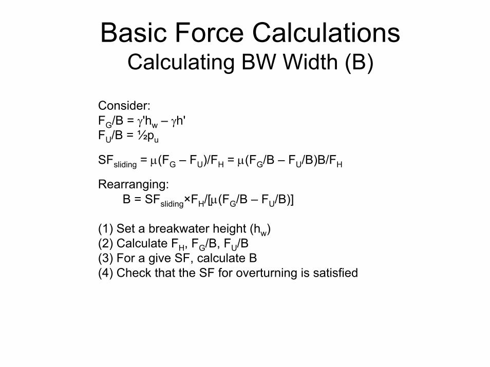
Basic Force CalculationsCalculating BW Width (B)
Consider:FG/B = γ'hw – γh'FU/B = ½pu
SFsliding = µ(FG – FU)/FH = µ(FG/B – FU/B)B/FH
Rearranging:B = SFsliding×FH/[µ(FG/B – FU/B)]
(1) Set a breakwater height (hw)(2) Calculate FH, FG/B, FU/B(3) For a give SF, calculate B(4) Check that the SF for overturning is satisfied
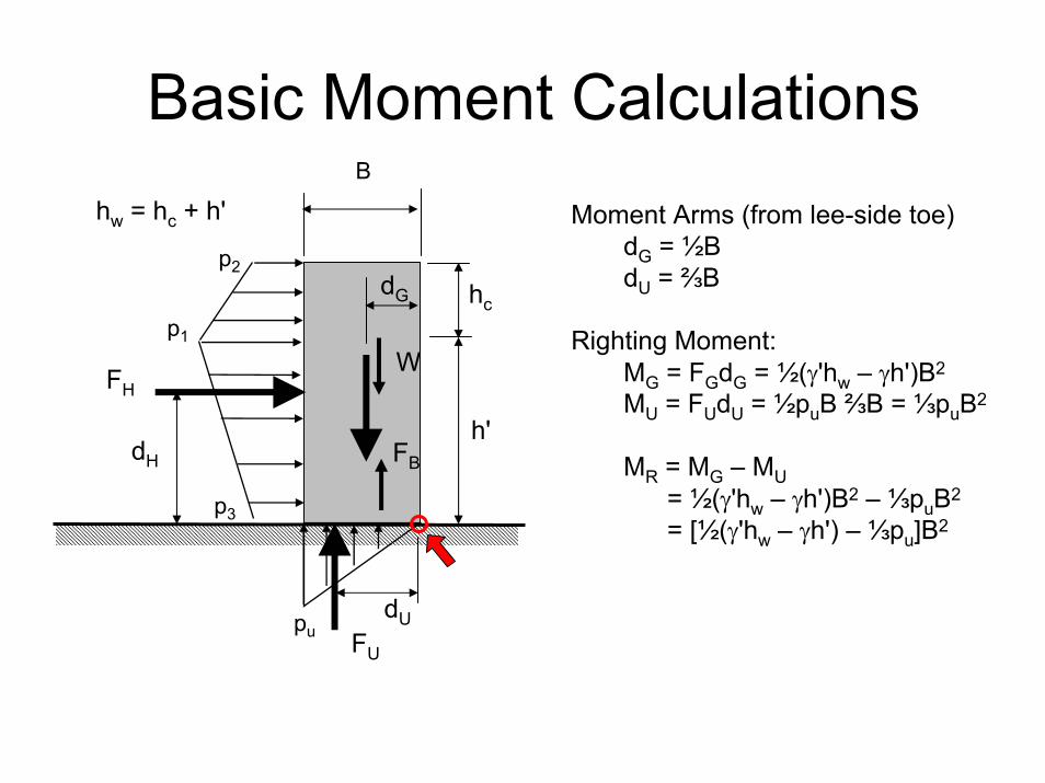
Basic Moment Calculations
p3
p2
W
FB
dU
dG
B
hw = hc + h' Moment Arms (from lee-side toe)dG = ½BdU = ⅔B
Righting Moment:MG = FGdG = ½(γ'hw – γh')B2
MU = FUdU = ½puB ⅔B = ⅓puB2
MR = MG – MU= ½(γ'hw – γh')B2 – ⅓puB2
= [½(γ'hw – γh') – ⅓pu]B2
hcp1
FH
h'dH
pu FU
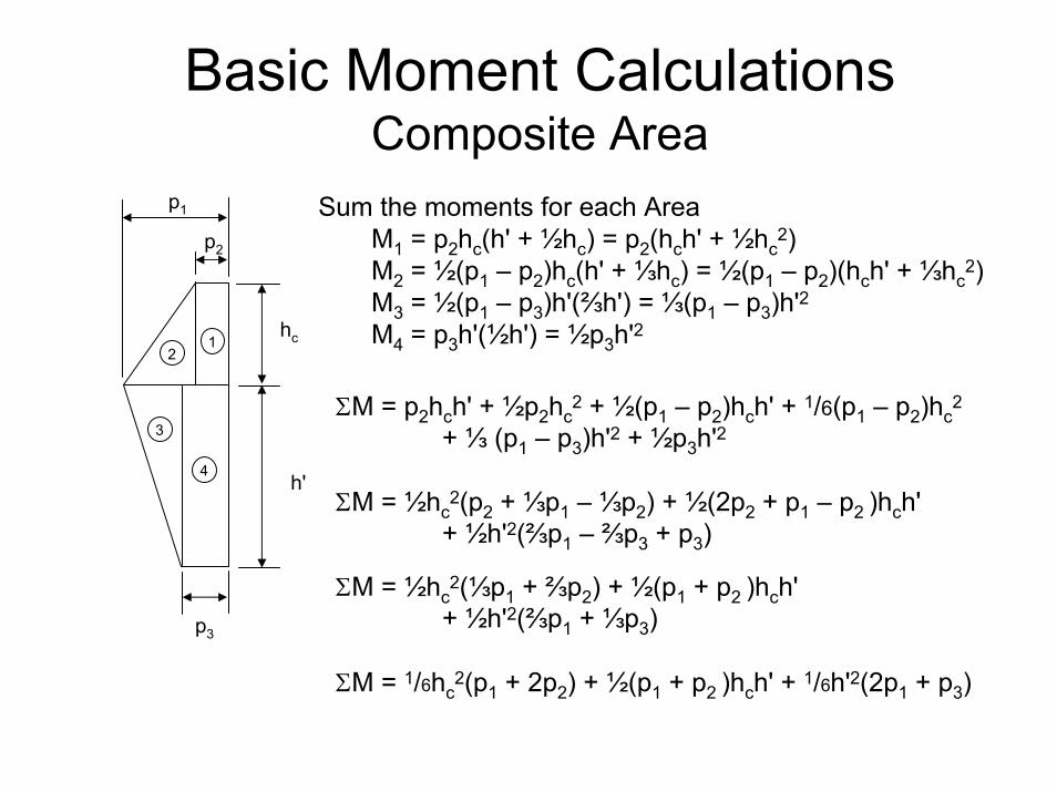
Basic Moment CalculationsComposite Area
Sum the moments for each AreaM1 = p2hc(h' + ½hc) = p2(hch' + ½hc
2)M2 = ½(p1 – p2)hc(h' + ⅓hc) = ½(p1 – p2)(hch' + ⅓hc
2)M3 = ½(p1 – p3)h'(⅔h') = ⅓(p1 – p3)h'2M4 = p3h'(½h') = ½p3h'21
3
4
2
p2
p1
p3
hc
h'
ΣM = p2hch' + ½p2hc2 + ½(p1 – p2)hch' + 1/6(p1 – p2)hc
2
+ ⅓ (p1 – p3)h'2 + ½p3h'2
ΣM = ½hc2(p2 + ⅓p1 – ⅓p2) + ½(2p2 + p1 – p2 )hch'
+ ½h'2(⅔p1 – ⅔p3 + p3)
ΣM = ½hc2(⅓p1 + ⅔p2) + ½(p1 + p2 )hch'
+ ½h'2(⅔p1 + ⅓p3)
ΣM = 1/6hc2(p1 + 2p2) + ½(p1 + p2 )hch' + 1/6h'2(2p1 + p3)
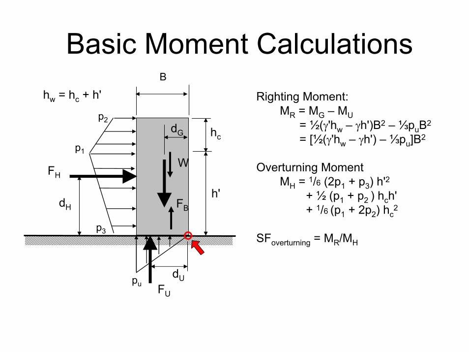
Basic Moment Calculations
p3
p2
W
FB
dU
dG
B
hw = hc + h' Righting Moment:MR = MG – MU
= ½(γ'hw – γh')B2 – ⅓puB2
= [½(γ'hw – γh') – ⅓pu]B2
Overturning MomentMH = 1/6 (2p1 + p3) h'2
+ ½ (p1 + p2 ) hch' + 1/6 (p1 + 2p2) hc
2
SFoverturning = MR/MH
hcp1
FH
h'dH
pu FU

Methods• Goda (VI-5-53, p. VI-5-139): non-breaking & breaking,
allows overtopping, modifications account for– Head-on breaking (VI-5-54)– Inclined/sloped walls (VI-5-56, VI-5-57)– Rubble mound protection of wall (VI-5-58)– Slit fronts and wave channels (VI-5-59)
• Sainflou (VI-5-52, p. VI-5-138): regular or irregular, non-breaking waves; cannot be used for breaking waves or overtopping
• Minikin (SPM): old breaking wave calculation, estimates over-predict by 15-18%, too conservative in most cases and could result in costly structures
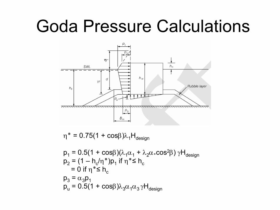
Goda Pressure Calculations
η ٭ = 0.75(1 + cosβ)λ1Hdesign
p1 = 0.5(1 + cosβ)(λ1α1 + λ2α٭cos2β) γHdesignp2 = (1 – hc/η ٭)p1 if η٭≤ hc
= 0 if η٭≤ hcp3 = α3p1pu = 0.5(1 + cosβ)λ3α1α3 γHdesign

Sainflou Pressure Calculations
δ0 = (πH2/L) coth(2πhs/L) … set-up
p2 = γH/cosh(2πhs/L)
under wave crestp1 = (p2 + γhs)(H + δ0)/(hs + H + δ0)
under wave troughp3 = γ(H – δ0)
Assume uplift pressure (pu) = p2
Note: overtopping and wave breaking are not allowed by Sainflou

Sainflou Force Calculations
p2
p1
H + δ0
hs
SWL
p2
Buoyant Weight (FG)W = γ'hwB, where hw = BW heightFB = γhsBFG = W – FB = (γ'hw – γhs)B
Uplift Force (FU)FU = ½p2B
Horizontal Force (FH)FH = ½p1 (hs + H + δ0) + ½p2hs
Alternates: FH = ½ p2(hs + H + δ0) + ½γhs(H + δ0)FH = ½ (p2 + γhs) (hs + H + δ0) – ½γhs
2

Horizontal ForceGoda vs. Sainflou
Sainflou
p3
p1
p2
FH
hc
h'
GodaGoda Sainflou
p1 ↔ p1p2 ↔ 0p3 ↔ p2hc ↔ H + δ0h' ↔ hs
p1
p2
H + δ0
FH
hs
GodaFH = ½(p1 + p2)hc + ½(p1 + p3)h'
Convert pressures to Sainflou definitionsFH = ½(p1 + 0)(H + δ0) + ½(p1 + p2)hs
= ½p1(hs + H + δ0) + ½p2hs= ½ (p2 + γhs)(H + δ0) + ½p2hs
FH = ½ p2(hs + H + δ0) + ½γhs(H + δ0)= ½ (p2 + γhs)(hs + H + δ0) – ½γhs
2
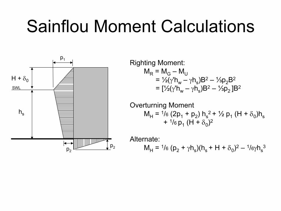
Sainflou Moment Calculations
p2
p1
H + δ0
hs
SWL
p2
Righting Moment:MR = MG – MU
= ½(γ'hw – γhs)B2 – ⅓p2B2
= [½(γ'hw – γhs)B2 – ⅓p2 ]B2
Overturning MomentMH = 1/6 (2p1 + p2) hs
2 + ½ p1 (H + δ0)hs+ 1/6 p1 (H + δ0)2
Alternate:MH = 1/6 (p2 + γhs)(hs + H + δ0)2 – 1/6γhs
3
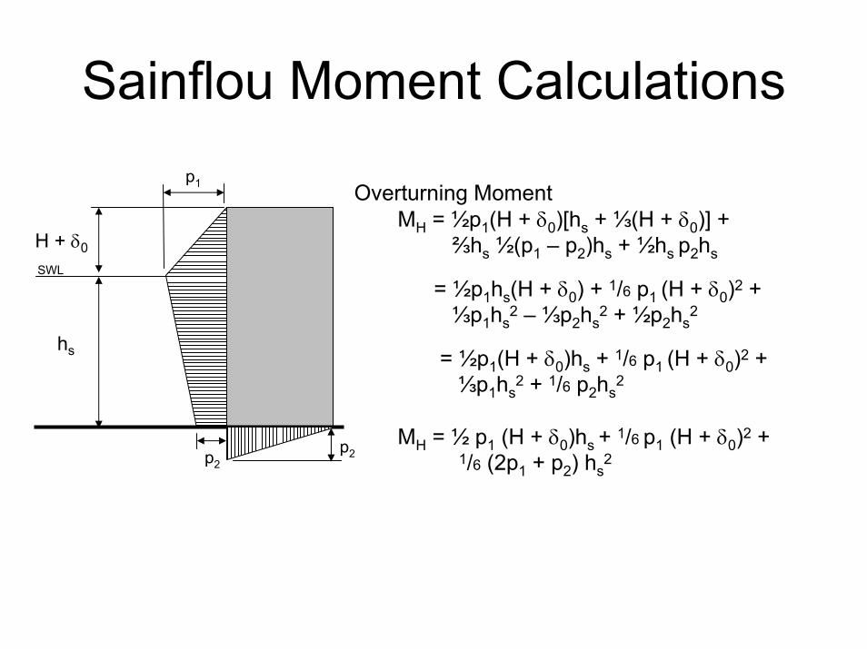
Sainflou Moment Calculations
Overturning MomentMH = ½p1(H + δ0)[hs + ⅓(H + δ0)] +
⅔hs ½(p1 – p2)hs + ½hs p2hs
= ½p1hs(H + δ0) + 1/6 p1 (H + δ0)2 +⅓p1hs
2 – ⅓p2hs2 + ½p2hs
2
= ½p1(H + δ0)hs + 1/6 p1 (H + δ0)2 +⅓p1hs
2 + 1/6 p2hs2
MH = ½ p1 (H + δ0)hs + 1/6 p1 (H + δ0)2 +1/6 (2p1 + p2) hs
2 p2
p1
H + δ0
hs
SWL
p2

Sainflou Moment CalculationsDerivation of Alternate MH
MH = 1/6 (2p1 + p2) hs2 + ½ p1 (H + δ0)hs + 1/6 p1 (H + δ0)2
= ⅓p1hs2 + 1/6 p2hs
2 + ½ p1 (H + δ0)hs + 1/6 p1 (H + δ0)2
= p1[⅓ hs2 + ½ (H + δ0)hs + 1/6 (H + δ0)2] + 1/6 p2hs
2
= 1/6 p1[2 hs2 + 3 (H + δ0)hs + (H + δ0)2] + 1/6 p2hs
2
= 1/6 p1{[hs2 + 2(H + δ0)hs + (H + δ0)2] + [hs
2 + (H + δ0)hs ]} + 1/6 p2hs2
= 1/6 p1[(hs + H + δ0)2 + hs(hs + H + δ0) ] + 1/6 p2hs2
= 1/6 (p2 + γhs)(H + δ0)[(hs + H + δ0) + hs ] + 1/6 p2hs2
= 1/6 (p2 + γhs)(H + δ0)(2hs + H + δ0) + 1/6 p2hs2
= 1/6 p2 [hs2 + 2hs(H + δ0) + (H + δ0)2] + 1/6 γhs[2hs(H + δ0)+ (H + δ0)2]
= 1/6 p2 (hs + H + δ0)2 + 1/6 γhs[hs2 + 2hs(H + δ0)+ (H + δ0)2] – 1/6γhs
3
= 1/6 p2 (hs + H + δ0)2 + 1/6 γhs(hs + H + δ0)2 – 1/6γhs3
MH = 1/6 (p2 + γhs)(hs + H + δ0)2 – 1/6γhs3

Minikin Pressure Calculationscombined
m
1
pmax = max dynamic pressure at SWLpm = dynamic pressurepd = hydrostatic pressure at depth d (including wave hydrostatic press)z = vertical distance from SWLh = the depth of water a distance L from the wall, h = d + LdmLd = the wavelength at depth dLh = the wavelength at depth hHb = breaker height
pmax = 101γd(1 + d/h)Hb/Lhpd = γ(d + ½Hb)
Note: (1) dynamic press force is
applied at the SWL(2) Minikin does not account
for water pressure on the opposite side (calculation is for a seawall)
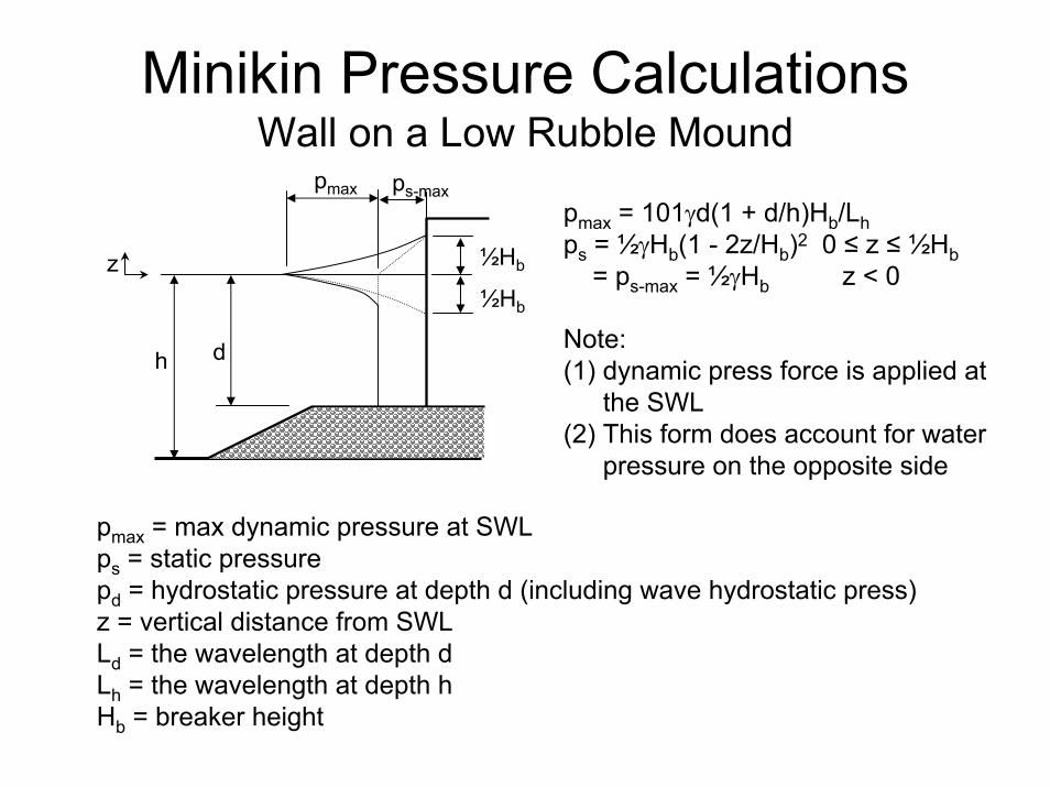
Minikin Pressure CalculationsWall on a Low Rubble Mound
pmax = 101γd(1 + d/h)Hb/Lhps = ½γHb(1 - 2z/Hb)2 0 ≤ z ≤ ½Hb
= ps-max = ½γHb z < 0
Note: (1) dynamic press force is applied at
the SWL(2) This form does account for water
pressure on the opposite side
h
ps-max
½Hb
½Hb
pmax
z
d
pmax = max dynamic pressure at SWLps = static pressurepd = hydrostatic pressure at depth d (including wave hydrostatic press)z = vertical distance from SWLLd = the wavelength at depth dLh = the wavelength at depth hHb = breaker height

Minikin Force CalculationsBuoyant Weight (FG) = W – FB = (γ'hw – γd)BUplift Force (FU) = ½ps-maxB = ¼ γHbB
combined
m1
Horizontal ForceFm = ⅓pmaxHb
Seawall: Fhydrostatic = ½pd(d + ½Hb) = ½ γ(d + ½Hb)2
BW: Fhydrostatic = ½ γ(d + ½Hb)2 - ½γd2
= ½ γHb(d + ¼Hb) (1) Seawall: FH = ⅓pmaxHb + ½ γ(d + ½Hb)2
(2) BW: FH = ⅓pmaxHb + ½ γHb(d + ¼Hb) ps-max
½Hb
½Hb
Horizontal ForceFm = ⅓pmaxHb
Fhydrostatic = ½ ps-max(½Hb) + ps-maxd= ps-max(d + ¼Hb)= ½γHb(d + ¼Hb)
FH = ⅓pmaxHb + ½ γHb(d + ¼Hb)
pmax
dh
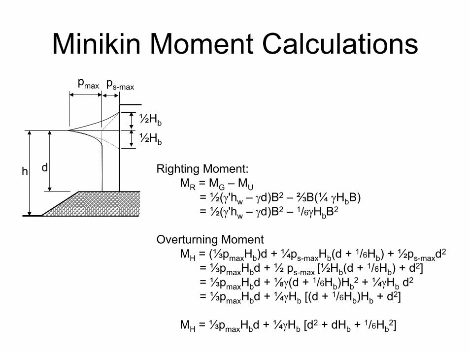
Minikin Moment Calculations
h
ps-max
½Hb
½Hb
pmax
d Righting Moment:MR = MG – MU
= ½(γ'hw – γd)B2 – ⅔B(¼ γHbB)= ½(γ'hw – γd)B2 – 1/6γHbB2
Overturning MomentMH = (⅓pmaxHb)d + ¼ps-maxHb(d + 1/6Hb) + ½ps-maxd2
= ⅓pmaxHbd + ½ ps-max [½Hb(d + 1/6Hb) + d2]= ⅓pmaxHbd + ⅛γ(d + 1/6Hb)Hb
2 + ¼γHb d2
= ⅓pmaxHbd + ¼γHb [(d + 1/6Hb)Hb + d2]
MH = ⅓pmaxHbd + ¼γHb [d2 + dHb + 1/6Hb2]

Minikin Pressure Calculations(wall with top below design breaker crest)
0
0.1
0.2
0.3
0.4
0.5
0.6
0.7
0.8
0.9
1
0 0.1 0.2 0.3 0.4 0.5 0.6 0.7 0.8 0.9 1
b'/Hb
rm
Apply reduction factors (rm & a) to dynamic component
1. Dynamic Force ComponentFm = rm ⅓pmaxHb
2. Dynamic Component of Overturning MomentMH = ⅓pmaxHbd + ¼γHb [d2 + dHb + 1/6Hb
2]Mm' = ⅓pmaxHb [d – (d + a)(1 – rm)]
= ⅓pmaxHb [rm(d + a) – a]
Hb
½ Hb
b'
0
0.1
0.2
0.3
0.4
0.5
0.6
0.7
0.8
0.9
1
0 0.1 0.2 0.3 0.4 0.5 0.6 0.7 0.8 0.9 1
b'/Hb
2a/Hb
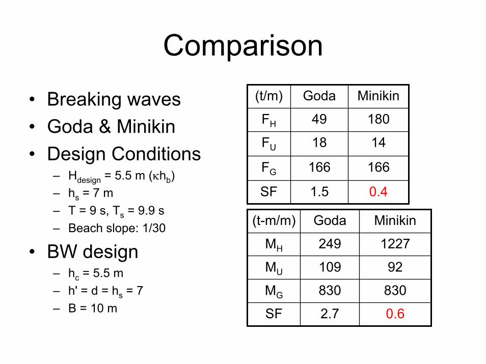
Comparison
• Breaking waves• Goda & Minikin• Design Conditions
– Hdesign = 5.5 m (κhb)– hs = 7 m– T = 9 s, Ts = 9.9 s– Beach slope: 1/30
• BW design– hc = 5.5 m– h' = d = hs = 7– B = 10 m
0.4
166
14
180
MinikinGoda(t/m)
1.5SF
166FG
18FU
49FH
0.62.7SF
830830MG
92109MU
1227249MH
MinikinGoda(t-m/m)
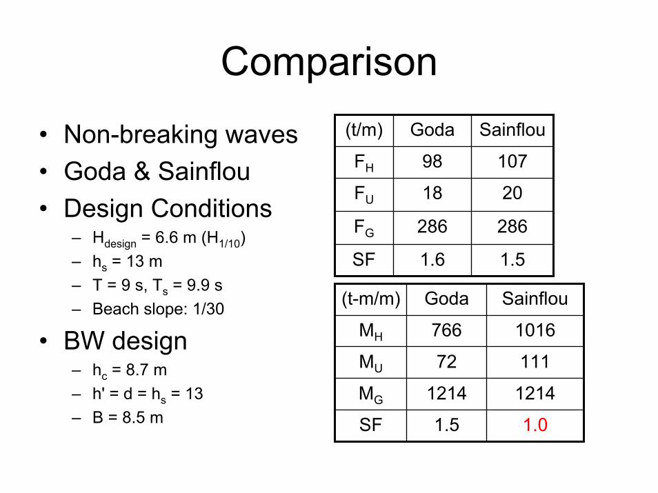
Comparison
• Non-breaking waves• Goda & Sainflou• Design Conditions
– Hdesign = 6.6 m (H1/10)– hs = 13 m– T = 9 s, Ts = 9.9 s– Beach slope: 1/30
• BW design– hc = 8.7 m– h' = d = hs = 13– B = 8.5 m
1.5
286
20
107
SainflouGoda(t/m)
1.6SF
286FG
18FU
98FH
1.01.5SF
12141214MG
11172MU
1016766MH
SainflouGoda(t-m/m)


