May 2017 DocID2574 Rev 31 1/53 This is information on a product in full production. www.st.com LFXX Very low drop voltage regulator with inhibit function Datasheet - production data Features Very low-dropout voltage (0.45 V) Very low quiescent current (typ. 50 μA in OFF mode, 500 μA in ON mode) Output current up to 500 mA Logic-controlled electronic shutdown Output voltages of 1.5; 1.8; 2.5; 3.3; 4.7; 5; 6; 8; 8.5; 9; 12 V Automotive grade product: 1.8 V, 2.5 V, 3.3 V, 5.0 V, 8.0 V, 8.5 V VOUT in DPAK and PPAK packages Internal current and thermal limit Only 2.2 μF for stability Available in ±1% (AB), ±1.5% (AC) or ±2% (C) selection at 25 °C Supply voltage rejection: 80 db (typ.) Temperature range: from -40 to 125 °C Description The LFXX is a very low drop regulator available in TO-220, TO-220FP, DPAK and PPAK packages and in a wide range of output voltages. The low drop voltage (0.45 V) and low quiescent current make it particularly suitable for low-noise, low-power applications and especially in battery- powered systems. In the 5 pin configuration (PPAK) a shutdown logic control function is available (pin 2, TTL compatible). This means that when the device is used as a local regulator, a part of the board can be put in standby, decreasing the total power consumption. In the three terminal configuration, the device has the same electrical performance, but it is fixed in ON state. It requires a capacitor of only 2.2 μF for stability, saving board space and costs. The LFXX is available as automotive grade in DPAK and PPAK packages, for the options of output voltages whose commercial part numbers are shown in the order codes. These devices are qualified according to the specification AEC-Q100 of the automotive market, in the temperature range -40 °C to 125 °C, and the statistical tests PAT, SYL, SBL are performed.
Transcript
May 2017 DocID2574 Rev 31 1/53
This is information on a product in full production. www.st.com
LFXX
Very low drop voltage regulator with inhibit function
Datasheet - production data
Features Very low-dropout voltage (0.45 V)
Very low quiescent current (typ. 50 µA in OFF mode, 500 µA in ON mode)
Output current up to 500 mA
Logic-controlled electronic shutdown
Output voltages of 1.5; 1.8; 2.5; 3.3; 4.7; 5; 6; 8; 8.5; 9; 12 V
Automotive grade product: 1.8 V, 2.5 V, 3.3 V, 5.0 V, 8.0 V, 8.5 V VOUT in DPAK and PPAK packages
Internal current and thermal limit
Only 2.2 µF for stability
Available in ±1% (AB), ±1.5% (AC) or ±2% (C) selection at 25 °C
Supply voltage rejection: 80 db (typ.)
Temperature range: from -40 to 125 °C
Description The LFXX is a very low drop regulator available in TO-220, TO-220FP, DPAK and PPAK packages and in a wide range of output voltages. The low drop voltage (0.45 V) and low quiescent current make it particularly suitable for low-noise, low-power applications and especially in battery-powered systems. In the 5 pin configuration (PPAK) a shutdown logic control function is available (pin 2, TTL compatible). This means that when the device is used as a local regulator, a part of the board can be put in standby, decreasing the total power consumption. In the three terminal configuration, the device has the same electrical performance, but it is fixed in ON state. It requires a capacitor of only 2.2 µF for stability, saving board space and costs. The LFXX is available as automotive grade in DPAK and PPAK packages, for the options of output voltages whose commercial part numbers are shown in the order codes. These devices are qualified according to the specification AEC-Q100 of the automotive market, in the temperature range -40 °C to 125 °C, and the statistical tests PAT, SYL, SBL are performed.
Symbol Parameter Test condition Min. Typ. Max. Unit
VO Output voltage
IO = 50 mA
VI = 10.5 V
Ta = 25 °C
8.33 8.5 8.67
V
IO = 50 mA
VI = 10.5 V 8.145
8.855
VI Operating input voltage IO = 500 mA
16 V
IO Output current limit Ta = 25 °C
1
A
∆VO Line regulation VI = 9.5 to 16 V
IO = 5 mA 8 44 mV
∆VO Load regulation VI = 9.8 V
IO = 5 to 500 mA 8 44 mV
Id Quiescent current
VI = 9.5 to 16 V
IO = 0 mA ON mode
0.7 2.5
mA VI = 9.8 to 16 V
IO = 500 mA 12
VI = 9 V OFF mode
70 160 µA
SVR Supply voltage rejection
IO = 5 mA
VI = 10.5 ± 1 V Ta =
25 °C
f = 120 Hz
72
dB f = 1 kHz
67
f = 10 kHz
57
eN Output noise voltage B = 10 Hz to 100 kHz
Ta = 25 °C 50
µV
Vd Dropout voltage IO = 200 mA
0.2 1.3
V IO = 500 mA
0.4 1.3
VIL Control input logic low
0.8 V
VIH Control input logic high
2
V
II Control input current
VI = 9 V
VC = 6 V
Ta = 25 °C
10
µA
CO Output bypass
capacitance
ESR = 0.1 to 10 Ω
IO = 0 to 500 mA 2 10
µF
Electrical characteristics LFXX
30/53 DocID2574 Rev 31
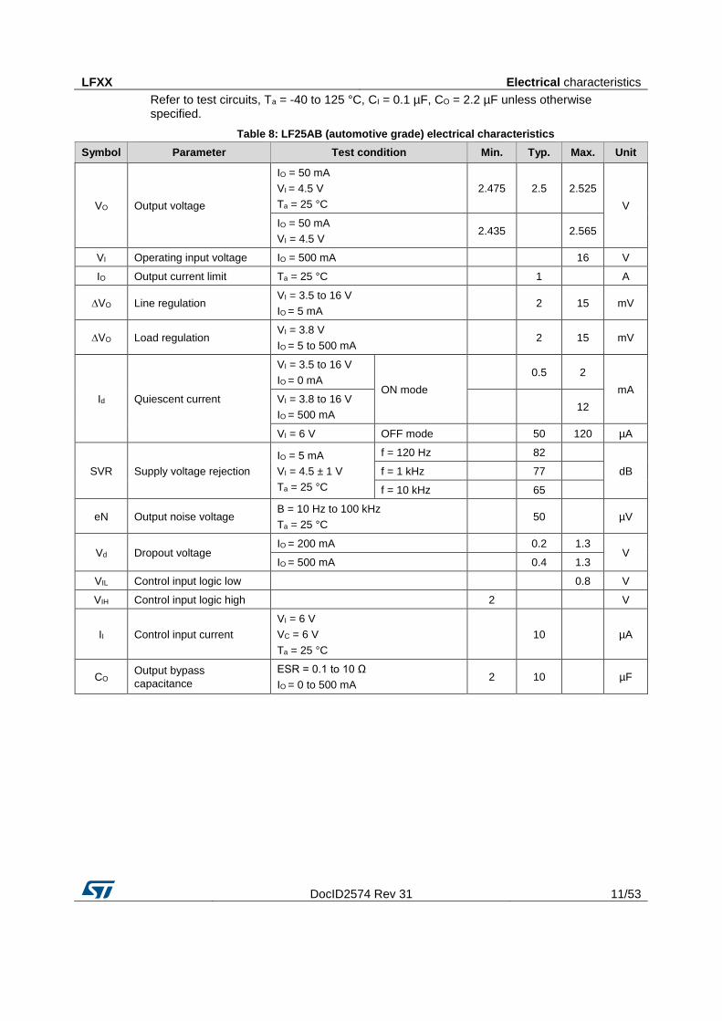
Refer to test circuits, TJ = 25 °C, CI = 0.1 µF, CO = 2.2 µF unless otherwise specified.
Table 27: LF90C electrical characteristics
Symbol Parameter Test condition Min. Typ. Max. Unit
VO Output voltage
IO = 50 mA
VI = 11 V 8.82 9 9.18
V IO = 50 mA
VI = 11 V
Ta = -25 to 85 °C
8.64
9.36
VI Operating input voltage IO = 500 mA
16 V
IO Output current limit
1
A
∆VO Line regulation VI = 10 to 16 V
IO = 5 mA 9 45 mV
∆VO Load regulation VI = 10.3 V
IO = 5 to 500 mA 9 45 mV
Id Quiescent current
VI = 10 to 16 V
IO = 0 mA ON mode
0.7 1.5
mA VI = 10.3 to 16V
IO = 500 mA 12
VI = 10 V OFF mode
70 140 µA
SVR Supply voltage rejection IO = 5 mA
VI = 11 ± 1 V
f = 120 Hz
71
dB f = 1 kHz
66
f = 10 kHz
56
eN Output noise voltage B = 10 Hz to 100 kHz
50
µV
Vd Dropout voltage IO = 200 mA
0.2 0.35
V IO = 500 mA
0.4 0.7
VIL Control input logic low Ta = -40 to 125 °C
0.8 V
VIH Control input logic high Ta = -40 to 125 °C 2
V
II Control input current VI = 10 V
VC = 6 V 10
µA
CO Output bypass capacitance ESR = 0.1 to 10 Ω
IO = 0 to 500 mA 2 10
µF
LFXX Electrical characteristics
DocID2574 Rev 31 31/53
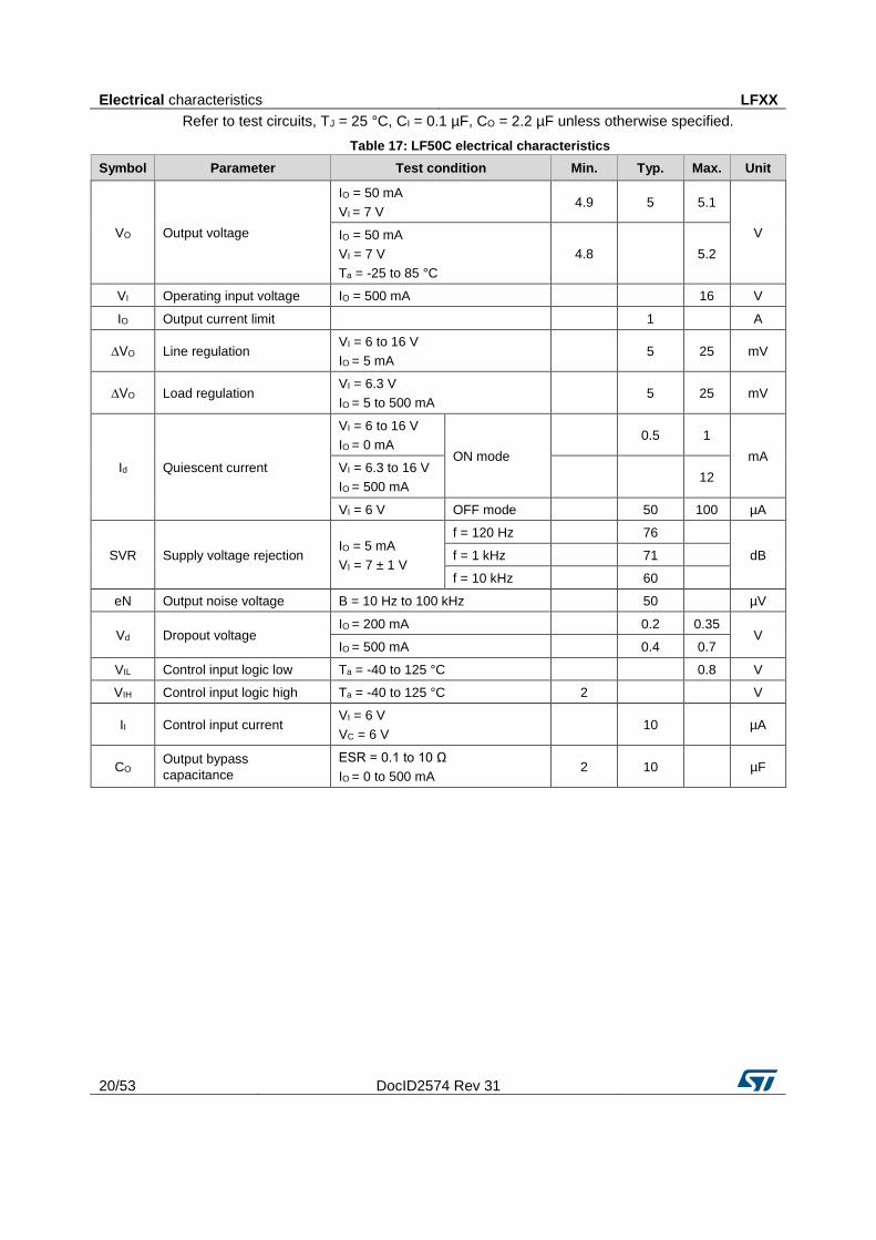
Refer to test circuits, TJ = 25 °C, CI = 0.1 µF, CO = 2.2 µF unless otherwise specified.
Table 28: LF120AB electrical characteristics
Symbol Parameter Test condition Min. Typ. Max. Unit
VO Output voltage
IO = 50 mA
VI = 15 V 11.88 12 12.12
V IO = 50 mA
VI = 15 V
Ta = -25 to 85 °C
11.76
12.24
VI Operating input voltage IO = 500 mA
16 V
IO Output current limit
1
A
∆VO Line regulation VI = 13 to 16 V
IO = 5 mA 12 60 mV
∆VO Load regulation VI = 13.3 V
IO = 5 to 500 mA 12 60 mV
Id Quiescent current
VI = 13 to 16 V
IO = 0 mA ON mode
0.7 1.5
mA VI = 13.3 to 16 V
IO = 500 mA 12
VI = 13 V OFF mode
70 140 µA
SVR Supply voltage rejection IO = 5 mA
VI = 14 ± 1 V
f = 120 Hz
69
dB f = 1 kHz
64
f = 10 kHz
54
eN Output noise voltage B = 10 Hz to 100 kHz
50
µV
Vd Dropout voltage IO = 200 mA
0.2 0.35
V IO = 500 mA
0.4 0.7
VIL Control input logic low Ta = -40 to 125 °C
0.8 V
VIH Control input logic high Ta = -40 to 125 °C 2
V
II Control input current VI = 13 V
VC = 6 V 10
µA
CO Output bypass capacitance ESR = 0.1 to 10 Ω
IO = 0 to 500 mA 2 10
µF
Electrical characteristics LFXX
32/53 DocID2574 Rev 31
Refer to test circuits, TJ = 25 °C, CI = 0.1 µF, CO = 2.2 µF unless otherwise specified.
Table 29: LF120C electrical characteristics
Symbol Parameter Test condition Min. Typ. Max. Unit
VO Output voltage
IO = 50 mA
VI = 14 V 11.76 12 12.24
V IO = 50 mA
VI = 14 V
Ta = -25 to 85 °C
11.52
12.48
VI Operating input voltage IO = 500 mA
16 V
IO Output current limit
1
A
∆VO Line regulation VI = 13 to 16 V
IO = 5 mA 12 60 mV
∆VO Load regulation VI = 13.3 V
IO = 5 to 500 mA 12 60 mV
Id Quiescent current
VI = 13 to 16 V
IO = 0 mA ON mode
0.7 1.5
mA VI = 13.3 to 16 V
IO = 500 mA 12
VI = 13 V OFF mode
70 140 µA
SVR Supply voltage rejection IO = 5 mA
VI = 14 ± 1 V
f = 120 Hz
69
dB f = 1 kHz
64
f = 10 kHz
54
eN Output noise voltage B = 10 Hz to 100 kHz
50
µV
Vd Dropout voltage IO = 200 mA
0.2 0.35
V IO = 500 mA
0.4 0.7
VIL Control input logic low Ta = -40 to 125 °C
0.8 V
VIH Control input logic high Ta = -40 to 125 °C 2
V
II Control input current VI = 13 V
VC = 6 V 10
µA
CO Output bypass
capacitance
ESR = 0.1 to 10 Ω
IO = 0 to 500 mA 2 10
µF
LFXX Typical performance characteristics
DocID2574 Rev 31 33/53
5 Typical performance characteristics Figure 4: Dropout voltage vs output current
Figure 5: Dropout voltage vs temperature
Figure 6: Supply current vs input voltage
Figure 7: Supply current vs input voltage (no load)
Typical performance characteristics LFXX
34/53 DocID2574 Rev 31
Figure 8: Short-circuit current vs input voltage
Figure 9: Supply current vs temperature
Unless otherwise specified VO(NOM) = 3.3 V.
LFXX Typical performance characteristics
DocID2574 Rev 31 35/53
Figure 10: Logic-controlled precision 3.3/5.0 V selectable output
Figure 11: Sequential multi-output supply
Typical performance characteristics LFXX
36/53 DocID2574 Rev 31
Figure 12: Multiple supply with ON/OFF toggle switch
Figure 13: Basic inhibit functions
LFXX Typical performance characteristics
DocID2574 Rev 31 37/53
Figure 14: Delayed turn-on
Figure 15: Low voltage bulb blinker
Package information LFXX
38/53 DocID2574 Rev 31
6 Package information
In order to meet environmental requirements, ST offers these devices in different grades of ECOPACK® packages, depending on their level of environmental compliance. ECOPACK® specifications, grade definitions and product status are available at: www.st.com. ECOPACK® is an ST trademark.
6.1 TO-220 (dual gauge) package information
Figure 16: TO-220 (dual gauge) package outline
LFXX Package information
DocID2574 Rev 31 39/53
Table 30: TO-220 (dual gauge) mechanical data
Dim. mm
Min. Typ. Max.
A 4.40
4.60
b 0.61
0.88
b1 1.14
1.70
c 0.48
0.70
D 15.25
15.75
D1
1.27
E 10
10.40
e 2.40
2.70
e1 4.95
5.15
F 1.23
1.32
H1 6.20
6.60
J1 2.40
2.72
L 13
14
L1 3.50
3.93
L20
16.40
L30
28.90
∅P 3.75
3.85
Q 2.65
2.95
Package information LFXX
40/53 DocID2574 Rev 31
6.2 TO-220 (single gauge) package information
Figure 17: TO-220 (single gauge) package outline
LFXX Package information
DocID2574 Rev 31 41/53
Table 31: TO-220 (single gauge) mechanical data
Dim. mm
Min. Typ. Max.
A 4.40
4.60
b 0.61
0.88
b1 1.14
1.70
c 0.48
0.70
D 15.25
15.75
E 10.00
10.40
e 2.40
2.70
e1 4.95
5.15
F 0.51
0.60
H1 6.20
6.60
J1 2.40
2.72
L 13.00
14.00
L1 3.50
3.93
L20
16.40
L30
28.90
∅P 3.75
3.85
Q 2.65
2.95
Package information LFXX
42/53 DocID2574 Rev 31
6.3 TO-220FP package information
Figure 18: TO-220FP package outline
LFXX Package information
DocID2574 Rev 31 43/53
Table 32: TO-220FP package mechanical data
Dim. mm
Min. Typ. Max.
A 4.4
4.6
B 2.5
2.7
D 2.5
2.75
E 0.45
0.7
F 0.75
1
F1 1.15
1.70
F2 1.15
1.70
G 4.95
5.2
G1 2.4
2.7
H 10
10.4
L2
16
L3 28.6
30.6
L4 9.8
10.6
L5 2.9
3.6
L6 15.9
16.4
L7 9
9.3
Dia 3
3.2
Package information LFXX
44/53 DocID2574 Rev 31
6.4 TO-220 packing information
Figure 19: Tube for TO-220 (dual gauge) (mm.)
Figure 20: Tube for TO-220 (single gauge) (mm.)
LFXX Package information
DocID2574 Rev 31 45/53
6.5 DPAK package information
Figure 21: DPAK package outline
Package information LFXX
46/53 DocID2574 Rev 31
Table 33: DPAK mechanical data
Dim. mm
Min. Typ. Max.
A 2.20
2.40
A1 0.90
1.10
A2 0.03
0.23
b 0.64
0.90
b4 5.20
5.40
c 0.45
0.60
c2 0.48
0.60
D 6.00
6.20
D1
5.10
E 6.40
6.60
E1
4.70
e
2.28
e1 4.40
4.60
H 9.35
10.10
L 1.00
1.50
(L1)
2.80
L2
0.80
L4 0.60
1.00
R
0.20
V2 0°
8°
Figure 22: DPAK recommended footprint (dimensions are in mm)
LFXX Package information
DocID2574 Rev 31 47/53
6.6 PPAK package information
Figure 23: PPAK package outline
Package information LFXX
48/53 DocID2574 Rev 31
Table 34: PPAK mechanical data
Dim. mm
Min. Typ. Max.
A 2.2
2.4
A1 0.9
1.1
A2 0.03
0.23
B 0.4
0.6
B2 5.2
5.4
C 0.45
0.6
C2 0.48
0.6
D 6
6.2
D1
5.1
E 6.4
6.6
E1
4.7
e
1.27
G 4.9
5.25
G1 2.38
2.7
H 9.35
10.1
L2
0.8 1
L4 0.6
1
L5 1
L6
2.8
R
0.20
V2 0°
8°
LFXX Package information
DocID2574 Rev 31 49/53
6.7 PPAK and DPAK packing information
Figure 24: PPAK and DPAK tape
Package information LFXX
50/53 DocID2574 Rev 31
Figure 25: PPAK and DPAK reel
Table 35: PPAK and DPAK tape and reel mechanical data
Tape Reel
Dim. mm
Dim. mm
Min. Max. Min. Max.
A0 6.8 7 A
330
B0 10.4 10.6 B 1.5
B1
12.1 C 12.8 13.2
D 1.5 1.6 D 20.2
D1 1.5
G 16.4 18.4
E 1.65 1.85 N 50
F 7.4 7.6 T
22.4
K0 2.55 2.75
P0 3.9 4.1 Base qty. 2500
P1 7.9 8.1 Bulk qty. 2500
P2 1.9 2.1
R 40
T 0.25 0.35
W 15.7 16.3
LFXX Ordering information
DocID2574 Rev 31 51/53
7 Ordering information Table 36: Order code
Package Output voltage
(V) TO-220 TO-220
(dual gauge) TO-220FP
DPAK
(tape and reel)
PPAK
(tape and reel)
LF15ABDT-TR
1.5
LF18CDT-TR LF18CPT-TR 1.8
LF18CDT-TRY (1)
1.8
LF18ABDT-TR LF18ABPT-TR 1.8
LF25CDT-TR LF25CPT-TR 2.5
LF25CDT-TRY(1)
2.5
LF25ABDT-TR
2.5
LF25ABDT-TRY(1)
2.5
LF33CV LF33CV-DG
LF33CDT-TR LF33CPT-TR 3.3
LF33CDT-TRY(1) LF33CPT-TRY(1) 3.3
LF33ABV LF33ABV-DG
LF33ABDT-TR
3.3
LF50CV LF50CV-DG
LF50CDT-TR LF50CPT-TR 5
LF50CDT-TRY(1) LF50CPT-TRY(1) 5
LF50ABV LF50ABV-DG
LF50ABDT-TR LF50ABPT-TR 5
LF50ACP
5
LF50ABDT-TRY(1)
5
LF60CV
LF60CDT-TR
6
LF60ABV
LF60ABDT-TR
6
LF80CDT-TR
8
LF80CDT-TRY(1)
8
LF80ABDT-TR
8
LF85CDT-TR LF85CPT-TR 8.5
LF85CDT-TRY(1) LF85CPT-TRY(1) 8.5
LF90CV
LF90CPT-TR 9
LF120CDT-TR
12
LF120ABDT-TR
12
Notes:
(1)Qualified and characterized according to AEC Q100 and Q003 or equivalent, advanced screening according to AEC Q001 and Q002 or equivalent.
Revision history LFXX
52/53 DocID2574 Rev 31
8 Revision history Table 37: Document revision history
Date Revision Changes
21-Jun-2004 14 Document updating.
24-May-2006 15 Order codes updated.
02-Apr-2007 16 Order codes updated.
14-May-2007 17 Order codes updated.
26-Jul-2007 18 Add table 1 in cover page.
26-Nov-2007 19 Modified: Table 34.
16-Jan-2008 20 Added new order codes for automotive grade products see Table
34 on page 51.
12-Feb-2008 21 Modified: Table 34 on page 51.
10-Jul-2008 22 Modified: Table 34 on page 51.
05-May-2010 23 Added: Table 29 on page 41, fig 16, fig 17, fig 18 and fig 19.
16-Nov-2010 24 Modified: RthJC value for TO-220 Table 2 on page 7.
10-Feb-2012 25 Added: order code LF33CV-DG and LF33ABV-DG Table 34 on
page 51.
09-Mar-2012 26 Added: order code LF50ABV-DG Table 34 on page 51.
28-Feb-2014 27
Changed the part numbers LFxxAB and LFxxC to LFXX.
Changed the title.
Removed table from cover page.
Removed PENTAWATT package from the figure in cover page,
Updated output voltage values in Table 16 and added new
commercial type in TO-220FP in Table 35.
Minor text changes.
27-Jan-2017 30 Updated features in cover page. Added Table 14 and updated Table 35.
22-May-2017 31 Updated Table 36: "Order code".
Minor text changes.
LFXX
DocID2574 Rev 31 53/53
IMPORTANT NOTICE – PLEASE READ CAREFULLY
STMicroelectronics NV and its subsidiaries (“ST”) reserve the right to make changes, corrections, enhancements, modifications, and improvements to ST products and/or to this document at any time without notice. Purchasers should obtain the latest relevant information on ST products before placing orders. ST products are sold pursuant to ST’s terms and conditions of sale in place at the time of order acknowledgement.
Purchasers are solely responsible for the choice, selection, and use of ST products and ST assumes no liability for application assistance or the design of Purchasers’ products.
No license, express or implied, to any intellectual property right is granted by ST herein.
Resale of ST products with provisions different from the information set forth herein shall void any warranty granted by ST for such product.
ST and the ST logo are trademarks of ST. All other product or service names are the property of their respective owners.
Information in this document supersedes and replaces information previously supplied in any prior versions of this document.