98

Outline 2/ 98
1. What VHDL stands for?
2. History
3. Structure and elements of a VHDL-File
4. Simple logic and Boolean equation
5. Description of Hierarchical Structures
6. Process-Environment
7. Testbenches
8. Packages and Configurations

3/ 98
1. What VHDL stands for?
2. History
3. Structure and elements of a VHDL-File
4. Simple logic and Boolean equation
5. Description of Hierarchical Structures
6. Process-Environment
7. Testbenches
8. Packages and Configurations
What VHDL stands for? 4/ 98
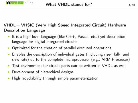
VHDL – VHSIC (Very High Speed Integrated Circuit) HardwareDescription Language
I It is a high-level-language (like C++, Pascal, etc.) yet descriptionlanguage for digital integrated circuits
I Optimized for the creation of parallel executed operationsI Enables the description of individual gates (including rise-, fall-, and
slew rate) up to the complete microprocessor (e.g.: ARM-Processor)I Test environment for circuit-parts can be written in VHDL as wellI Development of hierarchical designsI High recyclability through simple parameterization

Literature - Software 5/ 98
Book: VHDL-Synthese Unibibliothek C632J.Reichard, B. Schwarz FH2004.00033:?
FH2002.11800:?FH2000.13040:?
FPGA-Design & Synthese-Tools In order to use this tool, contact via internetXilinx ISE WebPACK is required:
http://www.xilinx.com/tools/webpack.html
GHDL Small Freeware CMD Compiler and Simulatorfor Windows and Linux:http://ghdl.free.fr (1 MB)
VHDL-Editors VHDL syntax-highlighting is supported bya lot of editors; templates are hardly available
Emacs ftp://ftp.gnu.org/gnu/emacs/windowsVery good Syntax-Highlighting Primary precompiled distribution:Templates and Macros for VHDL emacs-23.3-bin-i386.zip (42 MB)
For further information read http://www.ovgu.de/tornow/lehre/vhdl.htm
6/ 98
1. What VHDL stands for?
2. History
3. Structure and elements of a VHDL-File
4. Simple logic and Boolean equation
5. Description of Hierarchical Structures
6. Process-Environment
7. Testbenches
8. Packages and Configurations

History 7/ 98
I VHDL has been developed in the early 1980s with the assistance of theHigh-Speed-Integrated-Circuit-Research-Project, which had been initialisedby the U.S. Department of Defence.
I 1985 fist public version 7.2
I 1987 accepted by the IEEE as Standard IEEE 1076-1987
I The standard IEEE 1164 defines the standard-package (including thedata-type std_logic with 9 states), it substitutes the manufacturerspecific packages with the aim to standardize the description for simulations.
I 1994 the IEEE 1076-1993 is allocated as an improved version, but finds it‘sway only slowly into simulation tools. Especially the synthesis benefits fromit.
I In the end of 1995 the Standard IEEE 1076.3 has been added. Itcomplements the standard in order to substitute manufacturer specificpackages for the synthesis.

8/ 98
1. What VHDL stands for?
2. History
3. Structure and elements of a VHDL-File
4. Simple logic and Boolean equation
5. Description of Hierarchical Structures
6. Process-Environment
7. Testbenches
8. Packages and Configurations
Structure and elements of a VHDL-File 9/ 98
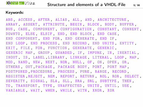
Keywords:
ABS , ACCESS , AFTER , ALIAS , ALL , AND , ARCHITECTURE ,
ARRAY , ASSERT , ATTRIBUTE , BEGIN , BLOCK , BODY , BUFFER ,
BUS , CASE , COMPONENT , CONFIGURATION , CONSTANT , CONNENT ,
DOWNTO , ELSE , ELSIF , END , END BLOCK , END CASE ,
END COMPONENT , END FOR , END GENERATE , END IF ,
END LOOP , END PROCESS , END RECORD , END UNITS , ENTITY ,
EXIT , FILE , FOR , FUNCTION , GENERATE , GENERIC ,
GENERIC MAP , GROUP , GUARDED , IF , IMPURE , IN , INERTIAL ,
INOUT , IS , LABEL ,LIBRARY , LINKAGE , LITERAL , LOOP , MAP ,
MOD , NAND , NEW , NEXT , NOR , NULL , OF , ON , OPEN , OR ,
OTHERS , OUT ,PACKAGE , PACKAGE BODY , PORT , PORT MAP ,
POSTPONED ,PROCEDURE , PROCESS , PURE , RANGE , RECORD ,
REGISTER ,REJECT , REM , REPORT , RETURN , ROL , ROR , SELECT ,
SEVERITY , SIGNAL , SLA , SLL , SRA , SRL , SUBTYPE , THEN ,
TO , TRANSPORT , TYPE , UNAFFECTED , UNITS , UNTIL , USE ,
VARIABLE , WAIT , WHEN , WHILE , WITH , XNOR , XOR

Structure of a VHDL-File 10/ 98
-- Basic -structure of an Entity
-- Integration of a library --> optional
[library <Name > ;]
[use <Name >.<package_name >.all;]
-- Entity --> Symbol with all in - and outputs
entity <Entity_name > is
generic [(< Declaration_of_parameters >);] -- optional
port (<Declaration_of_in -_and_output_ports >);
end <Entity_name >;
-- Architecture --> Logic behind the symbol
architecture <Architecture_name > of Entity_name is
[<Architecture_declarationen >] -- optional
begin -- <Architecture_name >
<VHDL -Instructions >;
end <Architekture_name >;

Structure elements 11/ 98
-- mux2x1.vhd
entity mux2x1 is
port (
E : in bit_vector (1 downto 0);
S : in bit;
Y : out bit
);
end mux2x1;
architecture struct of mux2x1 is
signal wire1 : bit;
signal wire2 : bit;
begin -- behaviour
wire1 <= E(0) and S;
wire2 <= E(1) and not S;
Y <= wire1 or wire2;
end struct;

Entity 12/ 98
entity mux2x1 is -- Entity -declaration
port ( -- Interface -declaration
E : in bit_vector (1 downto 0);-- Input data , Bus signal
S : in bit; -- Control -signal Input
Y : out bit -- Output -signal
);
end mux2x1;
PORT (list_of_names: mode type[; list_of_names: mode type]);
Port-Modus Application
in Input signal; must only be used on the right side of a signalassignment.
out Output signal; must only be used on the left side of a signalassignment.
buffer Output signal; may also stand on the right side of a signal assi-gnment
inout Bi-directional signal in combination with the specific data type:stdlogic (according to IEEE 1164)
[VHDL-Synthese] S.11

Architecture 13/ 98
I An “architecture“ consists of a declarationpart and an instruction part
I An ”architecture” can assume 3 differenttypes (Which can also occur combined):
I Structure-description (Combinationof design-objects: analogue tocircuits)
I Behaviour-description (Utilizationas high level language: abstractdescription)
I Test-bench (Description ofsignal-stimuli)
I All intern-instructions take place parallel(Also known as concurrent instructions)
I Concurrent instructions take placeevent-controlled
I More than one „architecture“ can exist forone entity (Selection over configuration)
architecture struct of mux2x1 is
signal wire1 : bit;
signal wire2 : bit;
begin -- behaviour
wire1 <= E(0) and S;
wire2 <= E(1) and not S;
Y <= wire1 or wire2;
end struct;

Overview of Data-Types 14/ 98
Predefined Data-Types 15/ 98
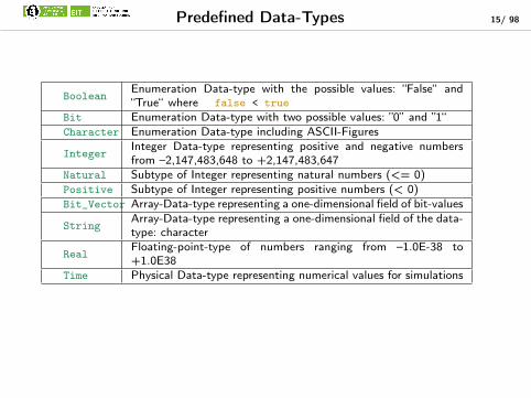
BooleanEnumeration Data-type with the possible values: “False“ and“True“ where false < true
Bit Enumeration Data-type with two possible values: ”0” and ”1“Character Enumeration Data-type including ASCII-Figures
IntegerInteger Data-type representing positive and negative numbersfrom –2,147,483,648 to +2,147,483,647
Natural Subtype of Integer representing natural numbers (<= 0)Positive Subtype of Integer representing positive numbers (< 0)Bit_Vector Array-Data-type representing a one-dimensional field of bit-values
StringArray-Data-type representing a one-dimensional field of the data-type: character
RealFloating-point-type of numbers ranging from –1.0E-38 to+1.0E38
Time Physical Data-type representing numerical values for simulations

Type-definitions 16/ 98
Example for:Integer-type-definition
type INTEGER is range -2147483648 to 2147483647;
Enumerate-type-definitiontype BOOLEAN is (false, true);
type BIT is (’0’,’1’);
Array-type-definitiontype BYTE is array (7 downto 0)of BIT;
type BIT_VECTOR is array (natural range <>)of BIT;
type 2D_BIT_VECTOR is array (natural range <>)of BIT_VECTOR(7 downto 0);
Record-type-definitiontype Holiday is record
year: INTEGER range 1900 to 2020;
month: INTEGER range 1 to 12;
day: INTEGER range 1 to 31;
accepted: BIT;
end record;
type holiday_array_type is array (natural range <>)of holiday;

Signal-Assignments 17/ 98
Architecture struct of example is
SIGNAL list_of_names: type;
SIGNAL wire1 , wire2 : bit; -- 1 Bit information
SIGNAL cable: bit_vector (7 downto 0); -- 8 Bit information Bus
SIGNAL big_cable : 2D_BIT_Vector (4 downto 0);
SIGNAL Hcable , Lcabel3 : bit_vector (3 downto 0);
SIGNAL company_holiday : Holiday_array_type (0 to 1000);
Begin
Wire1 <= cabel (0); -- single -signal of a bus
Hcabel <= cabel (7 downto 4); -- assignment of a signal -slice
Lcabel (2 downto 0) <= cabel (2 downto 0); -- assignment to a slice
-- to another slice
(a,b,c,d) <= Hcabel;-- assignment of a vector to single -signals
-- Access to n-dim Arrays
big_cabel (1) <=cabel;
wire2 <= big_cabel (0)(3);
-- Access to Record -Types
company_holiday (0).year <= 2012;
company_holiday (1) <= (year=> 2012, month=> 5, accepted => ’0’);
company_holiday (2) <= (2011,12,5,’1’);
End example;
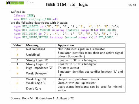
IEEE 1164: std_logic 18/ 98
Defined in:library IEEE;
use IEEE.std_logic_1164.all
are the following datatyopes with 9 states:type STD_ULOGIC is (‘U‘, ‘X‘, ‘0‘, ‘1‘, ‘Z‘, ‘W‘, ‘L‘, ‘H‘, ‘-‘);
type STD_ULOGIC_VECTOR is array (natural range <>)of STD_LOGIC;
type STD_LOGIC is (‘U‘, ‘X‘, ‘0‘, ‘1‘, ‘Z‘, ‘W‘, ‘L‘, ‘H‘, ‘-‘);
type STD_LOGIC_VECTOR is array (natural range <>)of STD_LOGIC;
Value Meaning ApplicationU Not Initialised Not initialised signal in a simulator
X Undefined Simulator identifies more than one active signaldriver (Bus-conflict)
0 Strong Logic ’0’ Equates to ’0’ of a bit-signal1 Strong Logic ’1’ Equates to ’1’ of a bit-signalZ High Impedance ’Z’ Tri-state output
W Weak Unknown Simulator identifies bus-conflict between ’L’ and’H’
L Weak Logic ’0’ Output with pull-down resistorH Weak Logic ’1’ Output with pull-up resistor
- Don’t Care Logic-status irrelevant; can be used for minimi-zation
Source: Book VHDL-Synthese 1. Auflage S.72
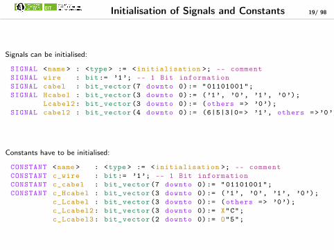
Initialisation of Signals and Constants 19/ 98
Signals can be initialised:
SIGNAL <name > : <type > := <initialisation >; -- comment
SIGNAL wire : bit:= ’1’; -- 1 Bit information
SIGNAL cabel : bit_vector (7 downto 0):= "01101001";
SIGNAL Hcabel : bit_vector (3 downto 0):= (’1’, ’0’, ’1’, ’0’);
Lcabel2: bit_vector (3 downto 0):= (others => ’0’);
SIGNAL cabel2 : bit_vector (4 downto 0):= (6|5|3|0= > ’1’, others =>’0’);
Constants have to be initialised:
CONSTANT <name > : <type > := <initialisation >; -- comment
CONSTANT c_wire : bit:= ’1’; -- 1 Bit information
CONSTANT c_cabel : bit_vector (7 downto 0):= "01101001";
CONSTANT c_Hcabel : bit_vector (3 downto 0):= (’1’, ’0’, ’1’, ’0’);
c_Lcabel : bit_vector (3 downto 0):= (others => ’0’);
c_Lcabel2: bit_vector (3 downto 0):= X"C";
c_Lcabel3: bit_vector (2 downto 0):= O"5";

Assignment of Different Number-Formats 20/ 98
Signal test : STD_LOGIC_VECTOR (12-1 downto 0);
Assignment of binary-numbers:test(0)<= ‘1‘; -- Assignment of one single bit
Test <= "B100111011001"; -- Assignment of a whole vector
Test <= "100111011001"; -- The display of the types can be left
-- out by binary-values!
Assignment of octal values takes place with 3 bits each:Test <= O"4273"; -- Results in bit string ’’100010111011‘‘
Assignment of hexadecimal values takes place with 4 bits each:Test <= X"AF5"; -- Results in bit string ’’101011110101’’
Assignment of decimal values to binary signals:Test <= 7500; --not defined
I It is not advised to use such assignments, since the strong typecast of VHDL is notallowed without a format-modification!
I most synthesis tools will post an error

Conversion of different datatypes 21/ 98
I VHDL is a strong typecasted programming languageI Only signals and variables of the same type can be allocated on each othersI Conversion functions need to be appliedI There are 2 different common method for converting numbers
I Synopsis-Libs: no industry standard but yet often usedI Numeric_STD-lib: vendor independed library from IEEE 1076.3
include of the Numeric_STD Library
library IEEE;
use IEEE.STD_LOGIC_1164.ALL;
use IEEE.NUMERIC_STD.ALL;
include of the Synopsis-Libraries (obsolete)
library IEEE;
use IEEE.STD_LOGIC_1164.ALL;
use IEEE.STD_LOGIC_ARITH.ALL;
--all vectors are interpreted as unsigned
use IEEE.STD_LOGIC_UNSIGNED.ALL;
-- or all vectors are interpreted as signed
--use IEEE.STD_LOGIC_SIGNED.ALL;
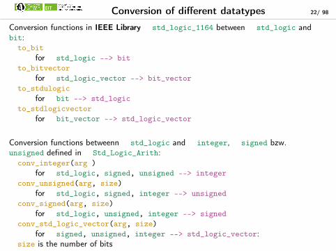
Conversion of different datatypes 22/ 98
Conversion functions in IEEE Library std_logic_1164 between std_logic andbit:to_bit
for std_logic --> bit
to_bitvector
for std_logic_vector --> bit_vector
to_stdulogic
for bit --> std_logic
to_stdlogicvector
for bit_vector --> std_logic_vector
Conversion functions betweenn std_logic and integer, signed bzw.unsigned defined in Std_Logic_Arith:conv_integer(arg )
for std_logic, signed, unsigned --> integer
conv_unsigned(arg, size)
for std_logic, signed, integer --> unsigned
conv_signed(arg, size)
for std_logic, unsigned, integer --> signed
conv_std_logic_vector(arg, size)
for signed, unsigned, integer --> std_logic_vector:size is the number of bits

Conversion function of NUMERIC-STD 23/ 98
Conversion functions between signed, unsigned and integer defined inNUMERIC_STD:to_integer(arg)
for signed, unsigned --> integer
to_unsigned(arg, size)
for natural --> unsigned
to_signed(arg, size)
for integer --> signed
size is the number of bits Typecasting between signed, unsigned and
std_logic_vector defined in NUMERIC_STD:std_logic_vector(arg)
for signed, unsigned --> std_logic_vector
unsigned(arg)
for std_logic_vector, signed --> unsigned
signed(arg)
for std_logic_vector,unsigned --> signed
size is the number of bits

Examples for Conversion functions 24/ 98
Example for synopsis-lib:
ieee.std_logic_1164.all;
ieee.std_logic_arith.all;
ieee.std_logic_signed.all;
. . .
Architecture structure of example1 is
Signal data_a : integer;
Signal data_b : std_logic_vector (14-1 downto 0);
Signal data_c : std_logic_vector (14-1 downto 0);
Begin
Data_a <= 12000;
Data_b <= Data_a; -- not defined!
Data_b <= conv_std_logic_vector(data_a , 14);
Data_c <= conv_std_logic_vector (13000 , 14);
End;
I synopsis-Library is not always exactI will the std_logic_vector contain
signed or unsigned numbers?I definition of the operators: +,-,*, results
in slow artihmeticI for high speed arithmetic vendor specific
hard coded arithmetic
Example for numeric_std:
ieee.std_logic_1164.all;
ieee.numeric_std.all;
. . .
Architecture structure of example2 is
Signal data_a : integer;
Signal data_b : std_logic_vector (14-1 downto 0);
Signal data_c : std_logic_vector (14-1 downto 0);
Begin
Data_a <= 12000;
Data_b <= Data_a; -- not defined!
Data_b <= std_logic_vector(to_signed(Data_a ,14));
Data_c <= std_logic_vector(to_unsigned (13000) , 14);
End;
I no direct conversion of integerto std_logic_vector
I a conversion to signed or unsigned isnecessary
I then a typecast to std_logic_vector
II definition of the operators: +,-,*,/
results in slow artihmeticI for high speed arithmetic vendor specific
hard coded arithmeticI is an independed standard should be used!

25/ 98
1. What VHDL stands for?
2. History
3. Structure and elements of a VHDL-File
4. Simple logic and Boolean equation
5. Description of Hierarchical Structures
6. Process-Environment
7. Testbenches
8. Packages and Configurations

Keywords of the Boolean Algebra 26/ 98
Architecture structure of example is
Signal ltg_a , ltg_b , ltg_c : std_logic;
Signal byte_a , byte_b , byte_c : std_logic_vector (7 downto 0);
Begin
ltg_a <=’1’;
ltg_b <=’0’;
ltg_c <= ltg_a and ltg_b; -- Result: ’0’
-- Application on Vectors:
Byte_a <= "01101011";
-- Bit string "01101011"
Byte_b <= (4|3|2|1=>’1’, others =>’0’);
-- Bit string "00011110"
Byte_c <= byte_a and byte_b;
-- Result Bit string "00001010""
End;

Example Logic 1: MUX 2in1 27/ 98
-- mux2x1.vhd
entity mux2x1 is
port (
E : in bit_vector (1 downto 0);
S : in bit;
Y : out bit
);
end mux2x1;
architecture struct of mux2x1 is
signal wire1 : bit;
signal wire2 : bit;
begin -- behaviour
wire1 <= E(0) and S;
wire2 <= E(1) and not S;
Y <= wire1 or wire2;
end struct;

Example logic 2: MUX 4in1 28/ 98

Example logic 2: MUX 4in1 29/ 98
-- mux4x1.vhd
LIBRARY ieee;
USE ieee.std_logic_1164.all;
entity mux4x1 is
port (
E : in std_logic_vector (3 downto 0);
S : in std_logic_vector (1 downto 0);
Y : out std_logic
);
end mux4x1;
architecture struct of mux4x1 is
signal wire1_mux1 , wire2_mux1 : std_logic;
signal wire1_mux2 , wire2_mux2 : std_logic;
signal wire1_mux3 , wire2_mux3 : std_logic;
signal wire_result1 , wire_result2 : std_logic;
begin
wire1_mux1 <= E(1) and S(0);
wire2_mux1 <= E(0) and not S(0);
wire_result1 <= wire1_mux1 or wire2_mux1;
wire1_mux2 <= E(3) and S(0);
wire2_mux2 <= E(2) and not S(0);
wire_result2 <= wire1_mux2 or wire2_mux2;
wire1_mux3 <= wire_result2 and S(1);
wire2_mux3 <= wire_result1 and not S(1);
Y <= wire1_mux3 or wire2_mux3;
end struct;

Example Logic 3: MUX 4in1 30/ 98
architecture struct2 of mux4x1 is
signal wire1 , wire2: std_logic;
signal wire3 , wire4 : std_logic;
begin
wire1 <= E(0) and not S(1) and not S(0);
wire2 <= E(1) and not S(1) and S(0);
wire3 <= E(2) and S(1) and not S(0);
wire4 <= E(3) and S(1) and S(0);
Y <= wire1 or wire2 or wire3 or wire4;
end struct2;

Conditional Signal-Assignment 31/ 98
-- Conditional signal -assignment
-- First choice has the highest Priority
and will be processed the fastest
-- Any amount of signals can be observed
architecture struct3 of mux4x1 is
begin -- behaviour
Y <= E(0) when S = "00" else
E(3) when S = "11" else
E(1) when S(0)= ’1’ else
E(2) when S(1)= ’1’;
end struct3;

Selective Signal-Assignment 32/ 98
-- Selective signal -assignment
-- All entries are equitable
-- Just one signal is observed
architecture struct4 of mux4x1 is
begin -- behaviour
with S select
Y <= E(0) when "00",
E(1) when "01",
E(2) when "10",
E(3) when "11";
end struct4;
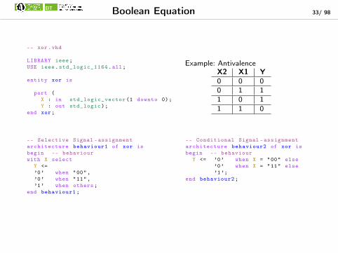
Boolean Equation 33/ 98
-- xor.vhd
LIBRARY ieee;
USE ieee.std_logic_1164.all;
entity xor is
port (
X : in std_logic_vector (1 downto 0);
Y : out std_logic);
end xor;
-- Selective Signal -assignment
architecture behaviour1 of xor is
begin -- behaviour
with X select
Y <=
’0’ when "00",
’0’ when "11",
’1’ when others;
end behaviour1;
Example: AntivalenceX2 X1 Y0 0 00 1 11 0 11 1 0
-- Conditional Signal -assignment
architecture behaviour2 of xor is
begin -- behaviour
Y <= ’0’ when X = "00" else
’0’ when X = "11" else
’1’;
end behaviour2;

Boolean Algebra 34/ 98
-- balgebr.vhd
-- XOR ,OR ,AND ,NAND
LIBRARY ieee;
USE ieee.std_logic_1164.all;
entity balgebr is
port (
X : in std_logic_vector (1 downto 0);
Y : out std_logic_vector (3 downto 0));
end balgebr;
-- Selective Signal -assignment
architecture behaviour1 of balgebr is
begin -- behaviour
with X select
Y <=
"0001" when "00",
"0110" when "11",
"1101" when others;
end behaviour1;
Example: AntivalenceX2 X1 XOR OR AND NAND0 0 0 0 0 10 1 1 1 0 11 0 1 1 0 11 1 0 1 1 0
-- Conditional signal -assignment
architecture behaviour2 of balgebr is
begin -- behaviour
Y <= "0001" when X = "00" else
"0110" when X = "11" else
"1101";
end behaviour2;

35/ 98
1. What VHDL stands for?
2. History
3. Structure and elements of a VHDL-File
4. Simple logic and Boolean equation
5. Description of Hierarchical Structures
6. Process-Environment
7. Testbenches
8. Packages and Configurations
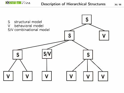
Description of Hierarchical Structures 36/ 98
??? 37/ 98

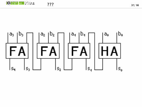
Example: Carry-Ripple-Adder 38/ 98
Input- and Output:I 2*n InputsI N+1 Outputs
Necessary Elements:I One Half adderI N-1 Full adder
I Two Half adders
I The carry ripple adder is used for adding multi-digit binary numbersI The carry-bit trickles through the full addersI Calculation is relatively slow, for the reason that the full adder can
only emit the right result, once the preceding full adder delivers thecarrier bit

Half Adder 39/ 98
Truth table ofa half adder
a b c s0 0 0 00 1 0 11 0 0 11 1 1 0
-- half_adder
-- MT 02.06.2004
library IEEE;
use IEEE.std_logic_1164.all;
entity hadder is
port (a, b : in STD_LOGIC;
c, s : out STD_LOGIC);
end hadder;
architecture arch of hadder is
begin
c <= a and b;
s <= a xor b;
end arch;

Assignments of components 40/ 98
entity hadder is
port (a, b : in STD_LOGIC;
c, s : out STD_LOGIC);
end hadder;
component hadder
port (
a, b : in STD_LOGIC;
c, s : out STD_LOGIC)←↩;
end component;
hadder1: hadder
port map (
a => a,
b => b,
c => c1 ,
s => si);
Name of the instance Name of the component
Signals of the architecturePorts

Full Adder 41/ 98
-- Fulladder
library IEEE;
use IEEE.std_logic_1164.all;
entity fadder is
port (a, b, cin : in STD_LOGIC;
cout , s : out STD_LOGIC);
end fadder;
architecture arch of fadder is
signal si , c1 , c2 : STD_LOGIC;
-- Declaration of a components
component hadder
port (
a, b : in STD_LOGIC;
c, s : out STD_LOGIC);
end component;
begin
hadder1: hadder -- First Instance
port map (
a => a,
b => b,
c => c1 ,
s => si);
hadder2: hadder -- Second Instance
port map (
a => si ,
b => cin ,
c => c2 ,
s => s); -- <-- Assignment
-- to the sum -output
cout <= c1 or c2;
end arch;
x y cin cout s0 0 0 0 00 0 1 0 10 1 0 0 10 1 1 1 01 0 0 0 11 0 1 1 01 1 0 1 01 1 1 1 1

Simulation of the Full Adder 42/ 98
-- Fulladder
library IEEE;
use IEEE.std_logic_1164.all;
entity fadder is
port (a, b, cin : in STD_LOGIC;
cout , s : out STD_LOGIC);
end fadder;
architecture arch of fadder is
signal si , c1 , c2 : STD_LOGIC;
-- Declaration of a components
component hadder
port (
a, b : in STD_LOGIC;
c, s : out STD_LOGIC);
end component;
begin
hadder1: hadder -- First Instance
port map (
a => a,
b => b,
c => c1 ,
s => si);
hadder2: hadder -- Second Instance
port map (
a => si ,
b => cin ,
c => c2 ,
s => s); -- <-- Assignment
-- to the sum -output
cout <= c1 or c2;
end arch;
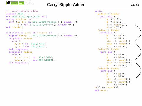
Carry-Ripple-Adder 43/ 98
-- carry -ripple -adder
library IEEE;
use IEEE.std_logic_1164.all;
entity cradder is
port (a, b : in STD_LOGIC_vector (4-1 downto 0);
s : out STD_LOGIC_vector (4 downto 0));
end cradder;
architecture arch of cradder is
signal carry : STD_LOGIC_vector (4-1 downto 0);
component hadder
port (
a, b : in STD_LOGIC;
c, s : out STD_LOGIC);
end component;
component fadder
port (
a, b, cin : in STD_LOGIC;
cout , s : out STD_LOGIC);
end component;
begin
hadder1: hadder
port map (
a => a(0),
b => b(0),
c => carry (0),
s => s(0));
fadder1: fadder
port map (
a => a(1),
b => b(1),
cin => carry (0),
cout => carry (1),
s => s(1));
fadder2: fadder
port map (
a => a(2),
b => b(2),
cin => carry (1),
cout => carry (2),
s => s(2));
fadder3: fadder
port map (
a => a(3),
b => b(3),
cin => carry (2),
cout => carry (3),
s => s(3));
s(4) <= carry (3);
end arch;
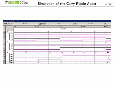
Simulation of the Carry-Ripple-Adder 44/ 98
Impact of parameters 45/ 98
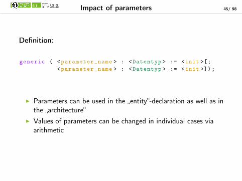
Definition:
generic ( <parameter_name > : <Datentyp > := <init >[;
<parameter_name > : <Datentyp > := <init >]);
I Parameters can be used in the „entity“-declaration as well as inthe „architecture“
I Values of parameters can be changed in individual cases viaarithmetic

Carry-Ripple-Adder with Parameters 46/ 98
-- carry -ripple -adder
-- MT 02.06.2004
--
library IEEE;
use IEEE.std_logic_1164.all;
entity cradder is
generic (d_width : natural := 4);
port (a, b : in STD_LOGIC_vector(d_width -1 downto 0);
s : out STD_LOGIC_vector(d_width downto 0));
end cradder;
architecture arch of cradder is
signal carry : STD_LOGIC_vector(d_width -1 downto 0);
component hadder
port (
a, b : in STD_LOGIC;
c, s : out STD_LOGIC);
end component;
component fadder
port (
a, b, cin : in STD_LOGIC;
cout , s : out STD_LOGIC);
end component;
begin
hadder1: hadder
port map (
a => a(0),
b => b(0),
c => carry (0),
s => s(0));
faddcnt: for i in d_width -1 downto 1 generate
fadder1: fadder
port map (
a => a(i),
b => b(i),
cin => carry(i-1),
cout => carry(i),
s => s(i));
end generate faddcnt;
s(d_width) <= carry(d_width -1);
end arch;
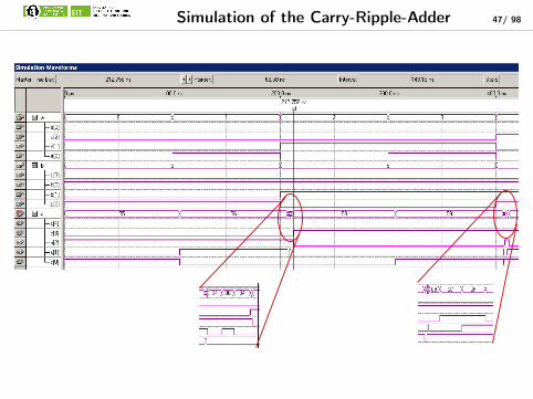
Simulation of the Carry-Ripple-Adder 47/ 98
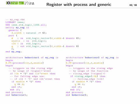
Register with process and generic 48/ 98
-- my_reg.vhd
LIBRARY ieee;
USE ieee.std_logic_1164.all;
entity my_reg is
generic (
d_width : natural := 4);
port (
d : in std_logic_vector(d_width -1 downto 0);
enable : in std_logic;
clk : in std_logic;
q : out std_logic_vector(d_width -1 downto 0)
);
end my_reg;
architecture behaviour1 of my_reg is
begin
D_FF:process(clk ,d,enable)
begin
-- triggers on the rising edge
-- by usage of <signal >’event
if clk = ’1’ and clk ’event then
-- for falling edge use:
-- if clk = ’0’ and clk ’event then
if enable = ’1’ then
q <= d;
end if;
end if;
end process;
end behaviour1;
architecture behaviour2 of my_reg is
begin
D_FF:process(clk ,d,enable)
begin
-- triggers on the rising edge
-- by usage of the function
-- rising_edge (<signal >)
if rising_edge(clk) then
-- falling_edge (clk)
if enable = ’1’ then
q <= d;
end if;
end if;
end process;
end behaviour2;

Carry-Ripple-Adder with Register 49/ 98-- carry -ripple -adder with Register
library IEEE;
use IEEE.std_logic_1164.all;
entity cradder is
generic (d_width : natural := 4;
pipe : boolean := false);
port (a, b : in STD_LOGIC_vector(d_width -1 ←↩downto 0);
clk , enable : in std_logic;
s : out STD_LOGIC_vector(d_width ←↩downto 0));
end cradder;
architecture arch of cradder is
signal carry : STD_LOGIC_vector(d_width -1 ←↩downto 0);
signal si : STD_LOGIC_vector(d_width downto 0);
signal enable : STD_LOGIC := ’1’;
component hadder
port (
a, b : in STD_LOGIC;
c, s : out STD_LOGIC);
end component;
component fadder
port (
a, b, cin : in STD_LOGIC;
cout , s : out STD_LOGIC);
end component;
component my_Reg
generic ( d_width : natural);
port (d : in std_logic_vector(d_width -1 ←↩downto 0);
enable : in std_logic;
clk : in std_logic;
q : out std_logic_vector(d_width -1 ←↩downto 0));
end component;
begin
hadder1:hadder
port map (
a => a(0),
b => b(0),
c => carry (0),
s => si(0));
faddcnt:for i in d_width -1 downto 1 generate
fadder1:fadder
port map (
a => a(i),
b => b(i),
cin => carry(i-1),
cout => carry(i),
s => si(i));
end generate faddcnt;
si(d_width) <= carry(d_width -1);
pipeline:if pipe generate
my_reg_i1:my_Reg
generic map (
d_width => d_width +1)
port map (
d => si ,
enable => enable ,
clk => clk ,
q => s);
end generate pipeline;
not_pipeline:if not pipe generate
s <= si;
end generate not_pipeline;
end arch;
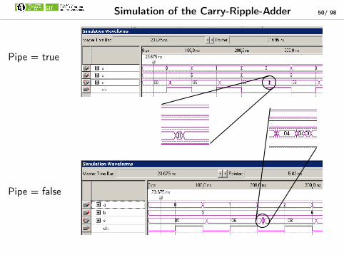
Simulation of the Carry-Ripple-Adder 50/ 98
Pipe = true
Pipe = false

Assignments of components 51/ 98
entity cradder is
generic (
d_width : natural := 4;
pipe : boolean := false);
port (
a, b :in STD_LOGIC_vector(d_width -1 downto 0);
clk : in std_logic;
enable : in std_logic := ’1’;
s :out STD_LOGIC_vector(d_width downto 0));
end cradder;
component cradder
generic (
d_width : natural;
pipe : boolean);
port (
a, b : in STD_LOGIC_vector(←↩d_width -1 downto 0);
clk : in std_logic;
s : out STD_LOGIC_vector(←↩d_width downto 0));
end component;
cradder1 : cradder
generic map (
d_width => 8,
pipe => pipe)
port map (
a => siga ,
b => sigb ,
clk => Mclk ,
s => sigs);
Name of the instance Name of the component
Signals of the architectureSignalPorts
Assignment of the parameter in the architecture
GenericPortsportsandgene-ricswithan in-itiali-sation(e.g.ena-ble)canbeskipedforcom-po-nentandin-stan-ciati-on

Generate-Assignment 52/ 98
Repeated execution:
<label 0> : for <variable > in <range > generate
<concurrent assignment >
end generate <label 0>;
Conditional execution:
<label 1> : if <condition > generate
<concurrent assignment >
end generate <label 1>;
Combination of both variants above:
<label 0> : for <variable > in <range > generate
<label 1> : if <condition > generate
<concurrent assignment >
end generate <label 1>;
end generate <label 0>;
I Creation of strongly parameterised componentsI Not needed logic will not be synthesisedI High re-usablility of the codeI Effective handling of projectsI Time saving after start-up phase

Shift register 53/ 98
I one input registerI 2 register in the centreI one register at the end
Functionality: taking the data at the beginning of theshift register and relaying with each clock
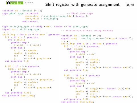
Shift register with generate assignment 54/ 98
constant dw : natural := 10;
type pixel_type is record -- Pixel data type
grayvalue : std_logic_vector(dw -1 downto 0;
data_valid : std_logic;
end record;
type shift_reg_type is array (srn -1 downto 0) of pixel_type;
signal sr : shift_reg_type;
. . .
Shift_Reg : for n in 0 to srn -1 generate
R_A : if n = 0 generate
sra : my_Reg
generic map (
d_width => d_width)
port map (
d => datain ,
enable => enable ,
clk => clk ,
q => sr(n).grayvalue);
end generate R_A;
R_ME : if n > 0 generate
SRME : my_Reg
generic map (
d_width => d_width)
port map (
d => sr(n-1).grayvalue ,
enable => enable ,
clk => clk ,
q => sr(n).grayvalue);
);
end generate R_ME;
end generate Shift_Reg;
-- Alternative without using records
constant dw : natural := 10;
signal sreg : std_logic_vector(dw*srn -1 downto 0);
. . .
Shift_Reg: for n in 0 to srn -1 generate
R_A : if n = 0 generate
SRA: my_Reg
generic map (
d_width => dw)
port map (
d => datain ,
enable => enable ,
clk => clk ,
q => sreg((n+1)*dw -1 downto n*dw));
end generate R_A;
R_ME : if n > 0 generate
SRME: my_Reg
generic map (
d_width => dw)
port map (
d => sreg(n*dw -1 downto (n-1)*dw),
enable => enable ,
clk => clk ,
q => sreg((n+1)*dw -1 downto n*dw));
end generate R_ME;
end generate Shift_Reg;

55/ 98
1. What VHDL stands for?
2. History
3. Structure and elements of a VHDL-File
4. Simple logic and Boolean equation
5. Description of Hierarchical Structures
6. Process-Environment
7. Testbenches
8. Packages and Configurations
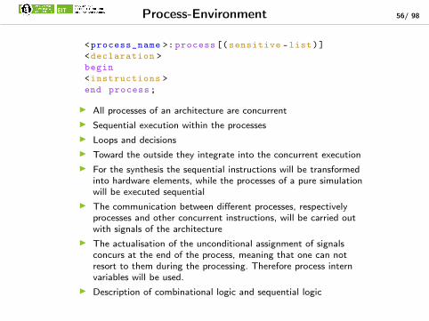
Process-Environment 56/ 98
<process_name >: process [(sensitive -list)]
<declaration >
begin
<instructions >
end process;
I All processes of an architecture are concurrentI Sequential execution within the processesI Loops and decisionsI Toward the outside they integrate into the concurrent executionI For the synthesis the sequential instructions will be transformed
into hardware elements, while the processes of a pure simulationwill be executed sequential
I The communication between different processes, respectivelyprocesses and other concurrent instructions, will be carried outwith signals of the architecture
I The actualisation of the unconditional assignment of signalsconcurs at the end of the process, meaning that one can notresort to them during the processing. Therefore process internvariables will be used.
I Description of combinational logic and sequential logic
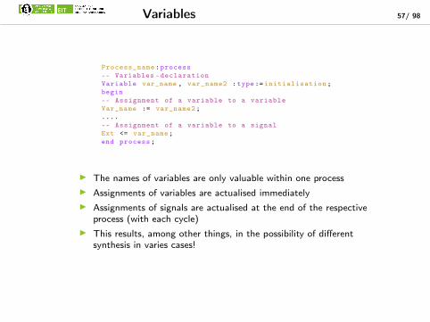
Variables 57/ 98
Process_name:process
-- Variables -declaration
Variable var_name , var_name2 :type:= initialisation;
begin
-- Assignment of a variable to a variable
Var_name := var_name2;
....
-- Assignment of a variable to a signal
Ext <= var_name;
end process;
I The names of variables are only valuable within one processI Assignments of variables are actualised immediatelyI Assignments of signals are actualised at the end of the respective
process (with each cycle)I This results, among other things, in the possibility of different
synthesis in varies cases!

Process without “Sensitive List” 58/ 98
-- latch.vhd
LIBRARY ieee;
USE ieee.std_logic_1164.all;
entity latch is
port (
E : in std_logic;
enable: in std_logic;
not_q : out std_logic;
q : out std_logic
);
end latch;
Begin
-- Example of a simple latch
-- Synchronised with architecture through wait
Pr_latch:process
begin
wait on e, enable until enable = ’1’;
q <= e;
not_q <= not e;
end process;
end behaviour;

Process without “Sensitive List” 59/ 98
SIGNAL Hcabel , Lcabel3 : bit_vector (3 downto 0);
...
Process_name:process(clk ,S,E)
VARIABLE list_of_names: type;
VARIABLE wire : bit; -- 1 Bit information
VARIABLE cabel : bit_vector (7 downto 0); -- 8 Bit information Bus
begin
Wire := cabel (0); -- single signal of a bus
Hcabel <= cabel (7 downto 4); -- assignment to a slice
Lcabel (2 downto 0) <= cabel (2 downto 0); -- assignment to a slice
-- to another slice
end process;

If Then 60/ 98
-- latch.vhd
LIBRARY ieee;
USE ieee.std_logic_1164.all;
entity my_latch is
port (
d : in std_logic;
clk : in std_logic;
not_q : out std_logic;
q : out std_logic
);
end my_latch;
architecture behaviour of my_latch is
begin
-- Example for a simple latch
-- Reacts through a sensitive list
-- This "latch" is not synchronised!
D_latch:process(clk ,d)
begin
if clk = ’1’ then
q <= d;
not_q <= not d;
end if;
end process;
end behaviour;

Edge Controlled Processing 61/ 98
-- latch.vhd
LIBRARY ieee;
USE ieee.std_logic_1164.all;
entity latch is
port (
e : in std_logic;
clk : in std_logic;
not_q : out std_logic;
q : out std_logic
);
end latch;
architecture behaviour of my_latch is
begin
-- Example for a simple latch
-- This "latch" is synchronised!
-- Function : Register!
D_latch:process(clk ,d)
begin
if clk = ’1’ and clk ’event then
q <= d;
not_q <= not d;
end if;
end process;
end behaviour;

Edge Controlled Processing with enable 62/ 98
-- my_reg.vhd
LIBRARY ieee;
USE ieee.std_logic_1164.all;
entity my_reg is
generic (
d_width : natural := 4);
port (
d : in std_logic_vector(d_width -1 downto 0);
enable : in std_logic;
clk : in std_logic;
q : out std_logic_vector(d_width -1 downto 0)
);
end my_reg;
architecture behaviour1 of my_reg is
begin
D_FF:process(clk ,d,enable)
begin
-- triggers on the rising edge
-- by usage of <signal >’event
if clk = ’1’ and clk ’event then
-- for falling edge use:
-- if clk = ’0’ and clk ’event then
if enable = ’1’ then
q <= d;
end if;
end if;
end process;
end behaviour1;
architecture behaviour2 of my_reg is
begin
D_FF:process(clk ,d,enable)
begin
-- triggers on the rising edge
-- by usage of the function
-- rising_edge (<signal >)
if rising_edge(clk) then
-- falling_edge (clk)
if enable = ’1’ then
q <= d;
end if;
end if;
end process;
end behaviour2;
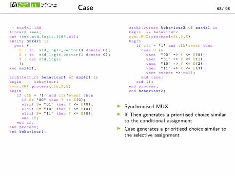
Case 63/ 98
-- mux4x1.vhd
library ieee;
use ieee.std_logic_1164.all;
entity mux4x1 is
port (
E : in std_logic_vector (3 downto 0);
S : in std_logic_vector (1 downto 0);
Y : out std_logic
);
end mux4x1;
architecture behaviour1 of mux4x1 is
begin -- behaviour1
sync_MUX:process(clk ,S,E)
begin
if clk = ’1’ and clk ’event then
if S= "00" then Y <= E(0);
elsif S= "01" then Y <= E(0);
elsif S= "10" then Y <= E(0);
elsif S= "11" then Y <= E(0);
end if;
end if;
end process;
end behaviour1;
architecture behaviour2 of mux4x1 is
begin -- behaviour2
sync_MUX:process(clk ,S,E)
begin
if clk = ’1’ and clk ’event then
case S is
when "00" => Y <= E(0);
when "01" => Y <= E(1);
when "10" => Y <= E(2);
when "11" => Y <= E(3);
when others => null;
end case;
end if;
end process;
end behaviour2;
I Synchronised MUXI If Then generates a prioritised choice similar
to the conditional assignmentI Case generates a prioritised choice similar to
the selective assignment

For-Loop 64/ 98
-- parity.vhd
library ieee;
use ieee.std_logic_1164.all;
entity parity is
port (
D : in std_logic_vector (3 downto 0);
even : out std_logic
);
end parity;
architecture behaviour of parity is
begin -- behaviour
par_gen:process(d)
Variable PAR: boolean;
Begin
par := false;
for i in 4-1 downto 0
if D(i) =’1’ then
par:= not par;
end if;
end loop;
If par then even <= ’1’;
else even <= ’0’;
end if;
end process;
end behaviour;
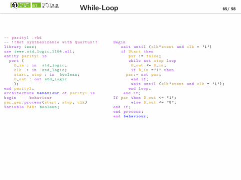
While-Loop 65/ 98
-- parity1 .vhd
-- !!Not synthesizable with Quartus !!
library ieee;
use ieee.std_logic_1164.all;
entity parity1 is
port (
D_in : in std_logic;
clk : in std_logic;
start , stop : in boolean;
D_out : out std_logic
);
end parity1;
architecture behaviour of parity1 is
begin -- behaviour
par_gen:process(start , stop , clk)
Variable PAR: boolean;
Begin
wait until (clk ’event and clk = ’1’)
if Start then
par := false;
while not stop loop
D_out <= D_in;
if D_in =’1’ then
par:= not par;
end if;
wait until (clk ’event and clk = ’1’);
end loop;
end if;
If par then D_out <= ’1’;
else D_out <= ’0’;
end if;
end process;
end behaviour;

Arithmetik in a Process 66/ 98
Process_name:process
-- Variables -declaration
Variable var1 , var2 :std_logic_vector (4 downto 0);
Variable var3 :std_logic_vector (5 downto 0);
Variable var4 :std_logic_vector (9 downto 0);
begin
-- Addition/Subtraction
Var3 := var1 (4)&var1 + var2 (4)&var2; -- extension for signed
Var3 := ’0’&var1 + ’0’&var2; -- extension for unsigned
-- Multiplication
Var4 := "00000"&var1 * "00000"&var2; -- extension for multiplication
-- & concatenates signals of vectortypes
end process;
I Addtion, Subtraction and Multiplication for integer-types is defined and no problemI Addition, subtraction and multiplication with vector types are only permitted and defined
for equal bit widthI packages std_logic_1164 and numeric_std have to be includedI Problems with equal bit widths => Results are truncated!
I Add/SubI No Carryout etc. => Tests for certain errors are not possible
I MultiplicationI Truncation of the upper half of the bits => Potentially results in major
error!I Advice:
I Expansion of the bit width prior to the operation in questionI Utilisation of the macro-function for arithmetic
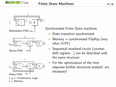
Finite State Machines 67/ 98
Medwedjew-FSM
Moore-FSM
Mealy-FSM
Synchronised Finite State machinesI State transition synchronisedI Memory = synchronised Flipflop (very
often D-FF)I Sequential standard-circuit (counter,
shift register...) can be described withthe same structure
I For the optimization of the timeresponse further structural analysis’ arenecessary!
f, g = Combinatory Logics = Memory

State Machines – Task Description 68/ 98
Current-pulse relays:I Pushing a button shall turn on the lightI Pushing the same button again shall turn off
the lightI Releasing the button will have no impact /
not change the state

Finite State Machines - Moore 69/ 98

State Machines – Moore (Symbolic) 70/ 98
library IEEE;
use IEEE.std_logic_1164.all;
entity ss1 is
port (clk: in STD_LOGIC;
SS: in STD_LOGIC;
Output: out STD_LOGIC);
end;
architecture ss1_arch of ss1 is
-- SYMBOLIC ENCODED state machine: ←↩current_pulse_relay
type current_pulse_relay_type is (AusD←↩, AusL , EinD , EinL);
signal current_pulse_relay: ←↩current_pulse_relay_type;
Begin
current_pulse_relay_machine: process (←↩clk)
begin
if clk ’event and clk = ’1’ then
case current_pulse_relay is
when AusD =>
if SS=’1’ then current_pulse_relay <= AusD;
elsif SS=’0’ then current_pulse_relay <= AusL;
end if;
when AusL =>
if SS=’0’ then current_pulse_relay <= AusL;
elsif SS=’1’ then current_pulse_relay <= EinD;
end if;
when EinD =>
if SS=’1’ then current_pulse_relay <= EinD;
elsif SS=’0’ then current_pulse_relay <= EinL;
end if;
when EinL =>
if SS=’0’ then current_pulse_relay <= EinL;
elsif SS=’1’ then current_pulse_relay <= AusD;
end if;
when others => null;
end case;
end if;
end process;
-- signal assignment statements for combinatorial ←↩outputs
Output_assignment:
Output <= ’0’ when (current_pulse_relay = AusD) else
’0’ when (current_pulse_relay = AusL) else
’1’ when (current_pulse_relay = EinD) else
’1’ when (current_pulse_relay = EinL) else
’1’;
end ss1_arch;

State Machines – Moore (Binary) 71/ 98
library IEEE;
use IEEE.std_logic_1164.all;
library SYNOPSYS;
use SYNOPSYS.attributes.all;
entity ss1 is
port (clk: in STD_LOGIC;
SS: in STD_LOGIC;
Output: out STD_LOGIC);
end;
architecture ss1_arch of ss1 is
-- BINARY ENCODED state machine: ←↩current_pulse_relay
type current_pulse_relay_type is (AusD←↩, AusL , EinD , EinL);
attribute enum_encoding of ←↩current_pulse_relay_type: type is
"00 " & -- AusD
"01 " & -- AusL
"10 " & -- EinD
"11"; -- EinL
signal current_pulse_relay: ←↩current_pulse_relay_type;
begin
current_pulse_relay_machine: process (clk)
begin
if clk ’event and clk = ’1’ then
case current_pulse_relay is
when AusD =>
if SS=’1’ then current_pulse_relay <= AusD;
elsif SS=’0’ then current_pulse_relay <= AusL;
end if;
when AusL =>
if SS=’0’ then current_pulse_relay <= AusL;
elsif SS=’1’ then current_pulse_relay <= EinD;
end if;
when EinD =>
if SS=’1’ then current_pulse_relay <= EinD;
elsif SS=’0’ then current_pulse_relay <= EinL;
end if;
when EinL =>
if SS=’0’ then current_pulse_relay <= EinL;
elsif SS=’1’ then current_pulse_relay <= AusD;
end if;
when others => null;
end case;
end if;
end process;
-- signal assignment statements for combinatorial ←↩outputs
Output_assignment:
Output <= ’0’ when (current_pulse_relay = AusD) else
’0’ when (current_pulse_relay = AusL) else
’1’ when (current_pulse_relay = EinD) else
’1’ when (current_pulse_relay = AusL) else
’1’;
end ss1_arch;

FSM- Simulation - Moore 72/ 98

Finite State Machines - Mealy 73/ 98

State Machines – Mealy (Binary) 74/ 98
library IEEE;
use IEEE.std_logic_1164.all;
library SYNOPSYS;
use SYNOPSYS.attributes.all;
entity ss2 is
port (clk: in STD_LOGIC;
SS: in STD_LOGIC;
Output: out STD_LOGIC);
end;
architecture ss2_arch of ss2 is
-- BINARY ENCODED state machine: ←↩current_pulse_relay
type current_pulse_relay_type is (AusD←↩, AusL , EinD , EinL);
attribute enum_encoding of ←↩current_pulse_relay_type:type is
"00 " & -- AusD
"01 " & -- AusL
"10 " & -- EinD
"11"; -- EinL
signal current_pulse_relay: ←↩current_pulse_relay_type;
begin
current_pulse_relay_machine: process (←↩clk)
begin
if clk ’event and clk = ’1’ then
case current_pulse_relay is
when AusD =>
if SS=’1’ then current_pulse_relay←↩<= AusD;
elsif SS=’0’ then ←↩current_pulse_relay <= AusL;
end if;
when AusL =>
if SS=’0’ then current_pulse_relay <= AusL;
elsif SS=’1’ then current_pulse_relay <= EinD;
end if;
when EinD =>
if SS=’1’ then current_pulse_relay <= EinD;
elsif SS=’0’ then current_pulse_relay <= EinL;
end if;
when EinL =>
if SS=’0’ then current_pulse_relay <= EinL;
elsif SS=’1’ then current_pulse_relay <= AusD;
end if;
when others => null;
end case;
end if;
end process;
-- signal assignment statements for combinatorial ←↩outputs
output_assignment:
output <=
’0’ when (current_pulse_relay = AusD and SS=’1’) else
’0’ when (current_pulse_relay = AusD and SS=’0’) else
’0’ when (current_pulse_relay = AusL and SS=’0’) else
’1’ when (current_pulse_relay = AusL and SS=’1’) else
’1’ when (current_pulse_relay = EinD and SS=’1’) else
’1’ when (current_pulse_relay = EinD and SS=’0’) else
’1’ when (current_pulse_relay = EinL and SS=’0’) else
’0’ when (current_pulse_relay = EinL and SS=’1’) else
’0’;
end ss2_arch;

FSM - Mealy/Moore: Comparision 75/ 98
Mealy
Moore

76/ 98
1. What VHDL stands for?
2. History
3. Structure and elements of a VHDL-File
4. Simple logic and Boolean equation
5. Description of Hierarchical Structures
6. Process-Environment
7. Testbenches
8. Packages and Configurations
Validation of VHDL-Desciptions 77/ 98
Integrated circuits are difficult to repair, but the usage of this circuits is stillincreasing in the last years especially in security relevant areas
I Integrated circuits have to work correctlyI The validation of hardware designs is very importantI The Semiconductor Industry (e.g. Infinion) is spending 60-80 % of the
development time for validationI This ratio is better for FPGA-Implementations, but still the validation is a vital point
and has a high priority
Two main problems:Testing if an Implementation:
I Meets specified formal characteristicsI Is an equivalent to an other implementation

General Steps of Validations 78/ 98
1. Formal specification of the designated behavior of a circuit2. Check of the VHDL-Description3. Logic synthesis und logic optimization
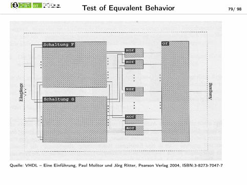
Test of Equvalent Behavior 79/ 98
Quelle: VHDL – Eine Einführung, Paul Molitor und Jörg Ritter, Pearson Verlag 2004, ISBN:3-8273-7047-7

Testbenches 80/ 98
I Testing environment for VHDL-descriptionsI Test benches are written in VHDL
I Entity – without in- or outputsI Usage of parameters is possibleI More data types and instructions necessary
I Specific for a designated design, which has to be verifiedI Sets inputs and outputs with various values
I For n inputs and m memories at least (n+1)*(m+1) data vectors are needed. Meetsspecified formal characteristics
I Are environments for the VHDL-designsI The designs are included as component named as DUT-”Design under test“.
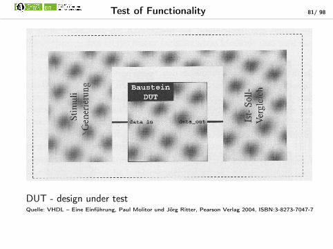
Test of Functionality 81/ 98
DUT - design under testQuelle: VHDL – Eine Einführung, Paul Molitor und Jörg Ritter, Pearson Verlag 2004, ISBN:3-8273-7047-7

Basic Structure of a Testbench 82/ 98
-- basic structure of a testbench
-- library include --> optional
[library < Name >;]
[use < Name >.< package name >.all;]
entity < Entity -name >_tb is -- name of the design + "_tb"
generic [(< deklarationen of Parameters >);] -- optional
end < Entity -name >_tb;
-- testbench -architecture
architecture TB_ < Architectur -name > of Entity -name_tb is
Component – Deklaration des DUT – Design under Test
[< deklarations in the architectur >] -- optional
begin -- < architectur -name >
Instance of the DUT
< VHDL -Instructions with stimuli and set -actual comparison >;
end < Architektur -name >;
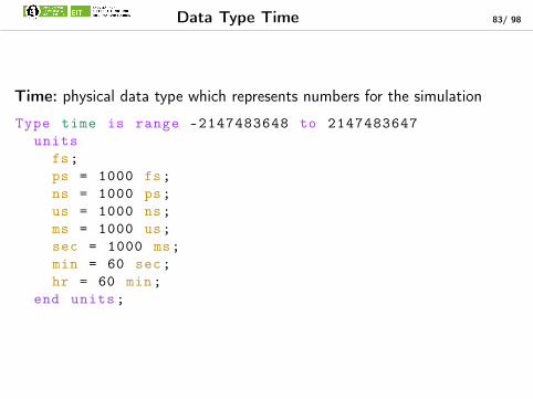
Data Type Time 83/ 98
Time: physical data type which represents numbers for the simulation
Type time is range –2147483648 to 2147483647
units
fs;
ps = 1000 fs;
ns = 1000 ps;
us = 1000 ns;
ms = 1000 us;
sec = 1000 ms;
min = 60 sec;
hr = 60 min;
end units;
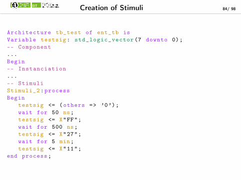
Creation of Stimuli 84/ 98
Architecture tb_test of ent_tb is
Variable testsig: std_logic_vector (7 downto 0);
-- Component
...
Begin
-- Instanciation
...
-- Stimuli
Stimuli_2:process
Begin
testsig <= (others => ’0’);
wait for 50 ns;
testsig <= X"FF";
wait for 500 ns;
testsig <= X"27";
wait for 5 min;
testsig <= X"11";
end process;

Creation of Cyclic Stimuli 85/ 98
Stimuli_1:process
Variable testsig: std_logic;
Begin
testsig := ’0’;
for i in 0 to 5000
testsig := not testsig;
wait for 10 ns;
end loop;
clock <= testsig;
end process;
Stimuli_2:process
Variable testsig: std_logic;
Begin
testsig := ’0’;
for i in 0 to 2500
testsig := not testsig;
wait for 20 ns;
testsig := not testsig;
wait for 5 ns;
end loop;
unsym_clock <= testsig;
end process;
symmetric clock asymmetric clock
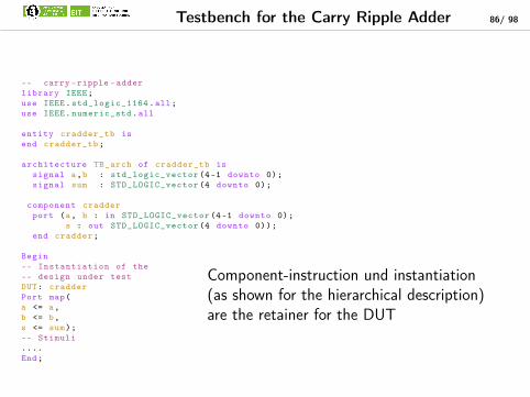
Testbench for the Carry Ripple Adder 86/ 98
-- carry -ripple -adder
library IEEE;
use IEEE.std_logic_1164.all;
use IEEE.numeric_std.all
entity cradder_tb is
end cradder_tb;
architecture TB_arch of cradder_tb is
signal a,b : std_logic_vector (4-1 downto 0);
signal sum : STD_LOGIC_vector (4 downto 0);
component cradder
port (a, b : in STD_LOGIC_vector (4-1 downto 0);
s : out STD_LOGIC_vector (4 downto 0));
end cradder;
Begin
-- Instantiation of the
-- design under test
DUT: cradder
Port map(
a <= a,
b <= b,
s <= sum);
-- Stimuli
....
End;
Component-instruction und instantiation(as shown for the hierarchical description)are the retainer for the DUT

Stimuli for the Carry Ripple Adder 87/ 98
stimuli:process
Variable at, bt :std_logic_vector (4-1 downto 0);
begin
Report "Validation starts ...";
for i in 0 to 2**4-1 loop
at:= std_logic_vector(to_signed(i,4));
for j in 0 to 2**4-1 loop
bt:= std_logic_vector(to_signed(j,4));
a<=at;
b<=bt;
wait for 10 ns;
assert sum=a(4-1)&a+b(4-1)&b
report "Sum calculation incorrect!";
end loop;
end loop;
Report "Validation end";
end process;
I Using both for-loops all possiblecombinations for the inputs are set
I std_logic_vector(to_signed(←↩i,n)) converts a decimal number ina std_logic_vector with thelength n ( Library ieee, use ←↩numeric_std)
I The assert-instruction is used forthe testing of the correctness ofassert sum=a(4-1)&a+b(4-1)&b
I If this is not correct the followingcomment will be written

88/ 98
1. What VHDL stands for?
2. History
3. Structure and elements of a VHDL-File
4. Simple logic and Boolean equation
5. Description of Hierarchical Structures
6. Process-Environment
7. Testbenches
8. Packages and Configurations

Packages 89/ 98
I Correspond like libraries of other programming languagesI Contain collections of common type definitions, operators,
declarations, functions, procedures, entities and componentsI A strict separation of the declaration part and the body of the package
(the body is often hidden to the user)I There are a lot of precompiled packages, where the body is compiled
and only the declaration part is visible to the user

Example for a Package 90/ 98
LIBRARY ieee;
USE ieee.std_logic_1164.ALL;
PACKAGE agp_arithmetic IS
CONSTANT Propagating : agpType := p;
CONSTANT Absorbing : agpType := a;
CONSTANT generating : agpType := g;
TYPE agpType is (a,g,p);
function stdlogic2agp (op1 , op2: in std_logic)
return agpType;
END package agp_arithmetic; Package body agp_arithmetic is
function stdlogic2agp (op1 , op2: in std_logic)
return agpType is
variable result: agpType;
begin
if (op1 xor op2)‘‘=1 then
result := Propagating;
elsif (op1 and op2)‘‘=1 then
result := Generating;
else
result := Absorbing
end if;
end;
End agp_arithmetic;
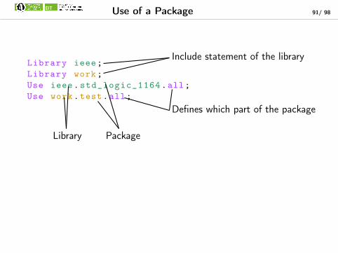
Use of a Package 91/ 98
Library ieee;
Library work;
Use ieee.std_logic_1164.all;
Use work.test.all;
Include statement of the library
Defines which part of the package
PackageLibrary

Characteristis 92/ 98
I The Standard Package is automatically included and contains allnecessary functions and definitions
I The library work contains compiled VHDL-code for simulation anduser generated packages
I The package ieee.std_logic_1164 contains extensions to thebasic specification of VHDL, especially the data type std_logic

Configurations 93/ 98
Configuration <name_of_the_conf > of <name_of_the_entity > ←↩is
for <name_of_the_architecture >
[for instantiation of the architecture;
assignment of an instance to one of its ←↩architectures
end for; ]
end for;
End[configuration] [name_of_the_entity]
I Using configurations a switching between various implementations of afunctionality and an entity is possible

Configuration for the Full-Adder 94/ 98
Assuming the architectures hadder_v1, hadder_v2, fadder_v1
and fadder_v2 exists; the simplest configuration derives as follows:Configuration CFG1a of fadder is
for fadder_v1
for all:hadder;
use entity work.hadder(hadder_v1);
end for;
end for;
End configuration fadder;
Configuration CFG1b of fadder is
for fadder_v1
for hadder1 , hadder2:hadder;
use entity work.hadder(hadder_v1);
end for;
end for;
End configuration fadder
Both configurations are identical, but cfg1a is written morecompactly. Furthermore the configuration doesn’t have to bechanged in order to add an hadder.

Configurations: Further Examples 95/ 98
Configuration CFG2 of fadder is
for fadder_v1
for hadder1:hadder;
use entity work.hadder(hadder_v2);
end for;
for hadder2:hadder;
use entity work.hadder(hadder_v1);
end for;
end for;
End configuration fadder; In this configuration differentarchitectures for different instancesare chosen.

Configurations: More Examples 96/ 98
Configuration CFG1 of cradder is
for cradder_v1
for fadder1:fadder
use entity work.fadder(fadder_v1);
for fadder_v1
for hadder1:hadder;
use entity work.hadder(hadder_v2);
end for;
for hadder2:hadder;
use entity work.hadder(hadder_v1);
end for;
end for;
end for;
for fadder2 , fadder3 , fadder4 :fadder;
use configuration work.cfg1a;
end for;
end for;
End configuration fadder;
By using the configurationfadder1 the knowledge ofthe full hierarchy isnecessary. For all otherinstances cfg1a is used.Thus the hierarchicaldescription can be used inconfigurations as well. Thenthe knowledge of the currentarchitecture is sufficient.

Summary 97/ 98
I Basic structure of a VHDL-FileI Signals and assignmentsI Combinatorics and Boolean algebraI Conditional and selective signal-assignmentsI Hierarchical Structure DescriptionI Impact of parametersI Process
I Edge-controlled and not edge-controlledI Representation of state machines
I Test benchesI Packages
I Basis structureI Configurations
I Different variations

98/ 98
Thanks