• VHSIC (Very High Speed Integrated Circuit) Hardware Description Language • Describes the behavior of an electronic circuit or system • First hardware description language to be standardized by IEEE through IEEE-1076 standard • IEEE-1164 – a multi-valued logic
Transcript
• VHSIC (Very High Speed Integrated Circuit) Hardware
Description Language
• Describes the behavior of an electronic circuit or
system
• First hardware description language to be standardized
by IEEE through IEEE-1076 standard
• IEEE-1164 – a multi-valued logic system.
• VHDL originated in the early 1980s
The American Department of Defense initiated the
development of VHDL in the early 1980s
because the US military needed a standardized method of
describing electronic systems
• VHDL was standardized in 1987 by the IEEE for
describing digital hardware used by industry worldwide
• It is now accepted as one of the most important
standard languages for
• specifying
• verifying
• designing of electronics
• Intended for synthesis as well as simulation
• All the major tool manufacturers now support the
VHDL standard
VHDL is a standard, technology/vendor independent language
Advantage: it is easy to move VHDL code between different
commercial platforms (Portable and reusable)
Concurrent statements not sequential VHDL is fully simulatable, not all constructs are
synthesizable
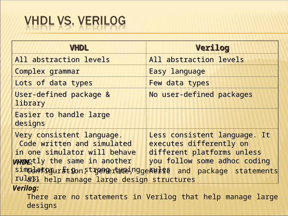
VHDLVHDL VerilogVerilog
All abstraction levelsAll abstraction levels All abstraction levelsAll abstraction levels
Complex grammarComplex grammar Easy languageEasy language
Lots of data typesLots of data types Few data typesFew data types
Easier to handle large designsEasier to handle large designs
Very consistent language. Code written and Very consistent language. Code written and simulated in one simulator will behave simulated in one simulator will behave exactly the same in another simulator.exactly the same in another simulator. E.g. E.g. strong typing rules.strong typing rules.
Less consistent language. Less consistent language. IItt executes executes differently on different platforms unlessdifferently on different platforms unless you follow some adhoc coding rulesyou follow some adhoc coding rules
VHDL:Configuration, generate, generic and package statements all help manage large design structures
Verilog:There are no statements in Verilog that help manage large designs
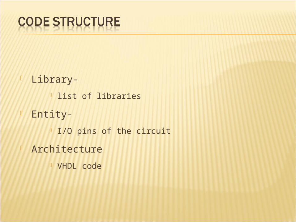
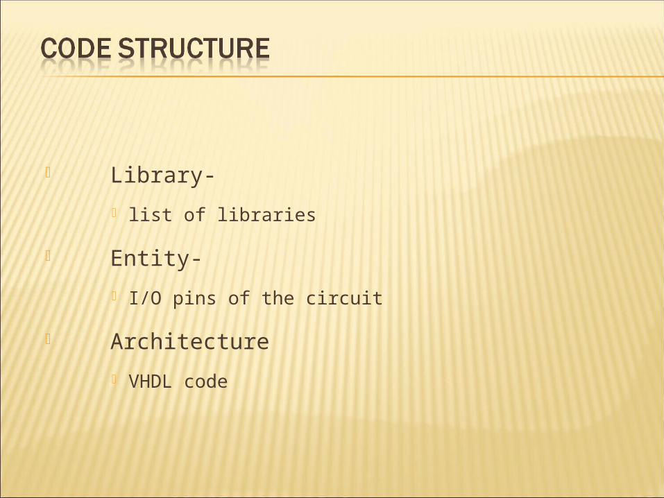
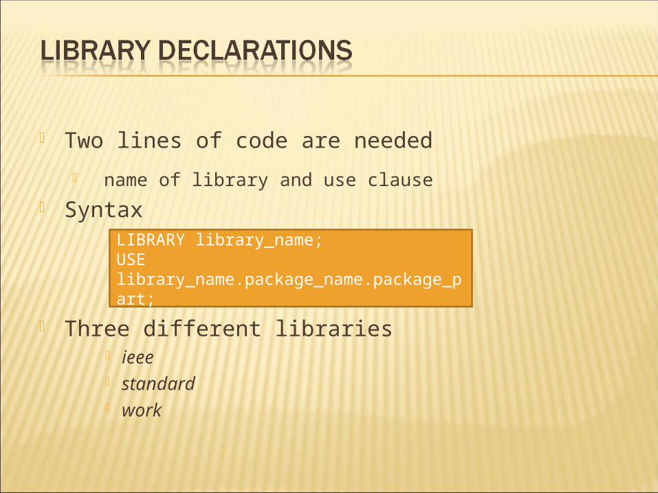
Library-
list of libraries
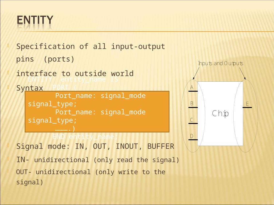
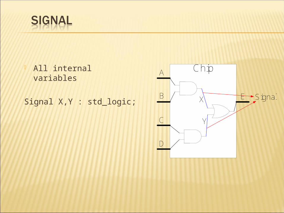
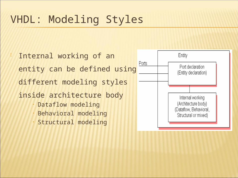
Entity-
I/O pins of the circuit
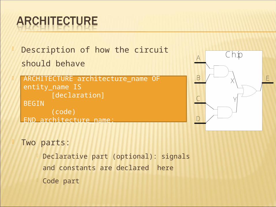
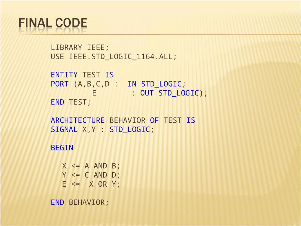
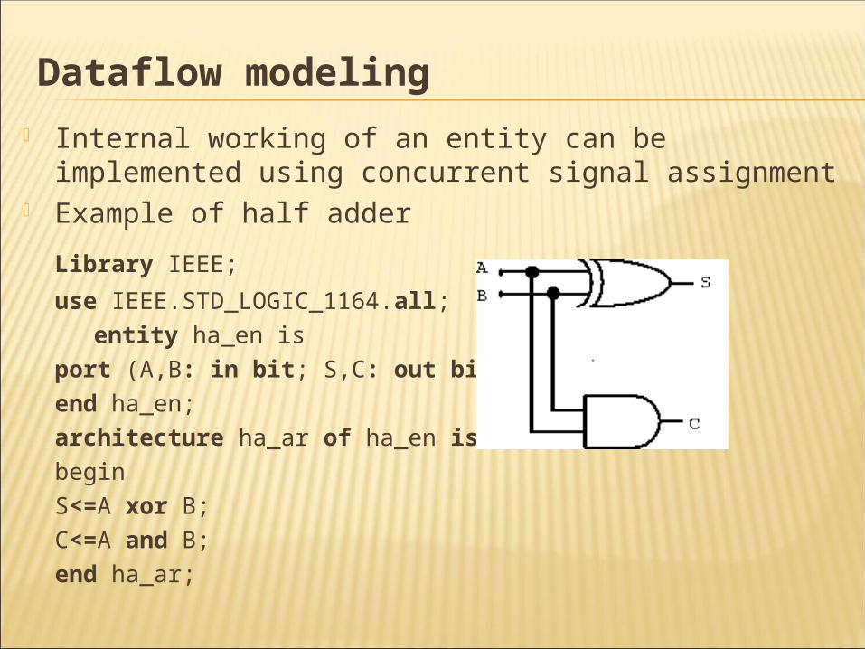
Architecture
VHDL code
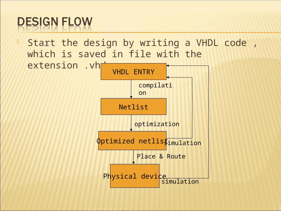
Start the design by writing a VHDL code , which is saved in file with the extension .vhd