VI. ICRF HEATING D. B. BATCHELOR (ORNL), M. D. CARTER (ORNL), R. H. GOULDING (ORNL), D. J. HOFFMAN (ORNL), J. C. HOSEA (PPPL), E. F. JAEGER (ORNL), S. M. KAm (PPPL), T. K. MAU (UCLA), C. K. PHILLIPS (PPPL), P. M. RYAN (ORNL), J. E. SCHAR,ER (Unher,ity of Wisconsin), D. W. SWAIN (ORNL), J. S. TOLLIVER (ORNL), J. R. WILSON (PPPL), and J. J. YUGO (ORNL) VLA. INTRODUCTlON Radio-frequency (RF) power in the ion cyclotron range of frequencies (ICRF) has been chosen as the primary auxiliary heating technique for BPX. This decision is based on the wide success of ICRF heating in existing large-scale experiments (JET, TFTR, JT-60), the capability of ion cyclotron waves to penetrate the high-density plasmas of BPX, the ability to concentrate ICRF power depo- sition near the plasma center, and the ready avail- ability of high-power sources in the appropriate fre- quency range. The primary task of the ICRF sys- tem is to heat to fusion temperatures. However, other important roles are envisaged, such as the stabilization of sawteeth, preheating of the plasma during current rampup, and study of plasma cur- rent profile control by means of fast-wave current drive. It is essential that the ICRF system be ca- pable of coupling power to the plasma effectively for all planned operating modes and that the ICRF system not rely on the tokamak to provide an ideal plasma tailored for ICRF heating. The baseline heating scenario is to use 3He mi- nority in the D-T fuel plasma. At full field, Be = 9 T, this requires fRF - 90 MHz. In lower field op eration, Be = 6 T, 3He minority at fm N 60 MHz and hydrogen minority at fm w 90 MHz will be used. The RF system will provide at least 20 MW coupled to the plasma in the frequency range of 60 to 90 MHz for pulses at least 15 s long. This is to be provided by 16 power sources. The possibility of an upgrade to 30 MW will be accommodated in the facility design. Operation in the range fuF = 120 to 135 MHz may also be possible at reduced power, permitting hydrogen minority or second-harmonic deuterium heating at full field. Section V1.B describes ICRF physics as applied to heating of BPX: heating scenarios, experimen- tal results from present tokamaks, power absorp tion, partitioning of power between various plasma species, and tail formation. The detailed RF sys- tem design is presented in the System Design De- scription. However, the antenna is the critical interface between the RF system and the fusion plasma. The amount of power that can be coupled to the plasma per antenna determines the number 1214 of antennas (and ports) as well as the design of the feed system and number of power sources. For fixed voltage handling capability, this power level is proportional to the antenna loading resistance, which is itself critically dependent on the plasma density profile near the antenna. Therefore, Sec. V1.B describes the physics of antenna design is- sues, particularly estimates of antenna loading. VLB. ICRF PHYSlCS VI&l. ICRF Heating Scenarios The standard operating scenario for bulk heating at full toroidal field (Bo = 9 T) is to use 3He minor- ity heating in a bulk plasma consisting of 50-50 D- T. To place the minority resonance on axis requires an RF frequency between 85 and 92 MHz, depend- ing on the Shafranov shift and plasma paramag- netism. Figure 6.1 shows the variation of cyclotron resonance frequency for various species across the 150 g 125 75 50 175 200 225 250 275 300 325 350 R (cm) Fig. 6.1. Cyclotron frequency of various plasma species versus major radius, & = 9 T. FUSION TECHNOLOGY VOL. 21 MAY 1992
Transcript
VI. ICRF HEATING
D. B. BATCHELOR (ORNL), M. D. CARTER (ORNL), R. H. GOULDING (ORNL), D. J. HOFFMAN (ORNL), J. C. HOSEA (PPPL), E. F. JAEGER (ORNL), S. M. KAm (PPPL),
T. K. MAU (UCLA), C. K. PHILLIPS (PPPL), P. M. RYAN (ORNL), J. E. SCHAR,ER (Unher,ity of Wisconsin), D. W. SWAIN (ORNL), J. S. TOLLIVER (ORNL), J. R. WILSON (PPPL), and
J. J. YUGO (ORNL)
VLA. INTRODUCTlON
Radio-frequency (RF) power in the ion cyclotron range of frequencies (ICRF) has been chosen as the primary auxiliary heating technique for BPX. This decision is based on the wide success of ICRF heating in existing large-scale experiments (JET, TFTR, JT-60), the capability of ion cyclotron waves to penetrate the high-density plasmas of BPX, the ability to concentrate ICRF power depo- sition near the plasma center, and the ready avail- ability of high-power sources in the appropriate fre- quency range. The primary task of the ICRF sys- tem is to heat to fusion temperatures. However, other important roles are envisaged, such as the stabilization of sawteeth, preheating of the plasma during current rampup, and study of plasma cur- rent profile control by means of fast-wave current drive. It is essential that the ICRF system be ca- pable of coupling power to the plasma effectively for all planned operating modes and that the ICRF system not rely on the tokamak to provide an ideal plasma tailored for ICRF heating.
The baseline heating scenario is to use 3He mi- nority in the D-T fuel plasma. At full field, Be = 9 T, this requires fRF - 90 MHz. In lower field op eration, Be = 6 T, 3He minority at fm N 60 MHz and hydrogen minority at fm w 90 MHz will be used. The RF system will provide at least 20 MW coupled to the plasma in the frequency range of 60 to 90 MHz for pulses at least 15 s long. This is to be provided by 16 power sources. The possibility of an upgrade to 30 MW will be accommodated in the facility design. Operation in the range fuF = 120 to 135 MHz may also be possible at reduced power, permitting hydrogen minority or second-harmonic deuterium heating at full field.
Section V1.B describes ICRF physics as applied to heating of BPX: heating scenarios, experimen- tal results from present tokamaks, power absorp tion, partitioning of power between various plasma species, and tail formation. The detailed RF sys- tem design is presented in the System Design De- scription. However, the antenna is the critical interface between the RF system and the fusion plasma. The amount of power that can be coupled to the plasma per antenna determines the number
1214
of antennas (and ports) as well as the design of the feed system and number of power sources. For fixed voltage handling capability, this power level is proportional to the antenna loading resistance, which is itself critically dependent on the plasma density profile near the antenna. Therefore, Sec. V1.B describes the physics of antenna design is- sues, particularly estimates of antenna loading.
VLB. ICRF PHYSlCS
VI&l. ICRF Heating Scenarios
The standard operating scenario for bulk heating at full toroidal field (Bo = 9 T) is to use 3He minor- ity heating in a bulk plasma consisting of 50-50 D- T. To place the minority resonance on axis requires an RF frequency between 85 and 92 MHz, depend- ing on the Shafranov shift and plasma paramag- netism. Figure 6.1 shows the variation of cyclotron resonance frequency for various species across the
150
g 125
75
50 175 200 225 250 275 300 325 350
R (cm)
Fig. 6.1. Cyclotron frequency of various plasma species versus major radius, & = 9 T.
FUSION TECHNOLOGY VOL. 21 MAY 1992
Batchelor et al. ICRF HEATING
COLD PLASMA ROOTS DT (3He) WARM PLASMA ROOTS DT (3He) 0.9 , I I I I I I I , 3.0 , I I I I I 1 I I I
(4
0.8 -
0.7 -
0.6 -
(b) \ \ \
Re (BERNSTEIN}\ \ I \
-7 0.5 - E s do.4 -
0.3 -
0.2 -
0.1 -
0 I I I
-100 -75 -50 -25 ( X
I I I 25 50 7
Re {FAST WAVE
: -0.5 -
. : : :
- -1.0 - : \ Im {BERNSTEIN}
-1.5 - i : ; ‘.
-2.0 - l . t
t ‘.
-2.5 - l . l . f
f -3.0 l . l l l l l l 1. l l
100 -25 -20 -15 -10 -5 0 5 10’ 15 20 X
1
Fig. 6.2. Solutions of the digersion relation Icl for 3He minority in D-T versus distance from the magnetic axis, n,(O) = 2 x 10 rne3, Bo = 9 T, $1 = 10 m-l, r/3Hs = 0.025: (a) cold plasma and (b) warm plasma, Te = Zj = 10 keV.
FUSION TECHNOLOGY VOL. 21 MAY 1992 1215
Batchelor et al. ICRF HEATING
plasma cross section for Bc = 9 T assuming vac- uum magnetic fields (B o( l/R).
Figure 6.2a shows a plot of the fast-wave per- pendicular wave number Icl obtained from the cold plasma dispersion relation versus distance x from the machine center (R = 2.59 m) in the equatorial plane. The parameters were q(O) = 2 x 10²’ rnm3, B(0) = 9 T, lcll = 10 m-l, VHe = 0.025, 77D =w = 0.475, and fRF = 90 MHz. With these parameters, the 3He cyclotron resonance is at z = 5 cm, and the ion-ion hybrid resonance is at x = 0. A thin evanescent layer (ICI imaginary, dotted curve) lies between the ion-ion hybrid layer and the fast-wave cutoff. There are no other cold plasma resonances, but there are evanescent zones in the low-density edge regions. Figure 6.2b shows solutions of the warm plasma dispersion relation near the resonance for the parameters above, with 2” = Ti = 15 keV. One can see the coupling to the short-wavelength Bernstein made (chain dot- ted curve) on the high-field (x < 0) side of the hybrid resonance. At this temperature, the fast- wave cutoff and hybrid resonance pair have been resolved by resonance broadening and mode con- version. Both fast-wave reflection and transmission are quite small.
120
100
N 80 E
60
20
i50 200 250 300 350
R (cm)
Fig. 6.3. Cyclotron frequency of various plasma species versus major radius, BO = 6 T.
With 3He resonant on axis, there are no hydra gen resonances in the device, although there is a deuterium resonance inboard of the machine cen- ter (R = 1.8 to 2 m). As the bulk plasma beta rises, direct second-harmonic heating of the tri- tium component, which coincides with the 3He res- onance, takes over. At the high densities employed on BPX, and because of the enhanced collisional- ity of 3He++, strong tail formation is not expected. This will result in bulk heating of the background ions rather than electrons.
minority hydrogen at fRF = 85 to 91 MHz. Fig- ure 6.3 shows the variation of cyclotron resonance frequency for various species across the plasma cross section for BO = 6 T. Again, with 3He reso nant on axis, there are no hydrogen resonances in the device although the deuterium resonance ap- pears on the inside region (R = 1.8 to 2 m). With hydrogen minority, a tritium second-harmonic res- onance appears on the inside edge of the plasma for Shafranov shifts greater than a few centime- ters. However, the one-pass absorption for the hy- drogen minority mode is so large (~100%) that no significant edge heating should occur.
With the high plasma current of BPX, confine- ment of tail populations is not expected to be an issue in any case, but will certainly not be impor- tant for 3He. Because the wave power propagates essentially radially inward from the antenna and since density gradients provide an additional re- fractive focusing, the wave energy and subsequent absorption is concentrated near the plasma cen- ter. The presence of the shear Alfven resonance near the inboard edge is an issue for further study, although this heating mode is routinely used in present tokamaks and no deleterious effects have been seen. The concern is that, due to the in- complete one-pass absorption for the 3He minority mode, edge absorption might occur at the shear Alfven resonance, which could give an undesirable heating profile or cause impurity problems.
Vi.B.2. Summary of Recent Experimental Results
By now there is a considerable data base on
At 213 field (Bo = 6 T), two heating modes are available, minority 3He at fm = 56 to 61 MHz and
ICRF with both 3He minority and hydrogen mi- nority modes at quite high power levels and plasma parameters. Some of the most encouraging re- sults have come from JET, where up to 22 MW. has been coupled to the plasma.’ Temperatures of G(O) = 11.5 keV and Ti(O) = 8 keV have been achieved with 18 MW in limiter discharges, where peaked density profiles created by pellet fueling are maintained for long periods of time (> 1 s). Very significant for BPX is that long, edge-localized mode (ELM) free H modes have been achieved with ICRF alone on JET (Ref. 2). Figure 6.4 shows an RF-produced H mode of 1.3-s duration in a double- null X-point discharge with Ip = 3 MA, BT = 2.8 T, and pkF = 7 MW. The electron temper- ature reaches 9.5 keV at the end of the H mode,
1216 FUSION TECHNOLOGY VOL. 21 MAY 1992
Time (s)
Fig. 6.4. H mode achieved on JET with 7 MW of ICRH alone.2
when the central density has risen to 3.7 x 10” rnT3 and the energy content given by the diamagnetic loop has reached 6 MJ. In these H modes, the con- finement time of the thermal component is about twice the L-mode value and is similar to values ob- tained with neutral injection at the same power level. Note that by feedback control of the fre- quency and plasma position, the loading resistance is held constant even during L-to-H and H-to-L mode transitions. By use of beryllium gettering of the machine and using solid beryllium as the Fara- day shield material, impurity problems directly as- sociated with ICRF heating have been eliminated. With respect to impurity behavior, density limits and characteristics of the H mode, ICRF heating is essentially indistinguishable from neutral beam injection. Another beneficial effect of ICRF power is the stabilization of sawteeth. Sawtooth-free pe-
FUSION TECHNOLOGY VOL. 21 MAY 1992 1217
Batchelor et al. ICRF HEATING
riods have been produced for up to 3 s in both deuterium and helium plasmas with either hydra gen or 3He minority heating.
Ion cyclotron resonance frequency heating has been used on TFTR to successfully heat plas- mas with densities approaching that required of BPX (Ref. 3). Figure 6.5 shows time traces of 3He minority heating of a pellet-fueled discharge with 4 MW of ICRF power. From the initial cen- tral electron temperature of Te(0) = 700 eV at n,(O) = 2.5 x 10²’ ms3, the temperature rises to >5 keV while the peak density stays above n,(O) = 1 x 1020 cm -3. The rapid rise in Z”(0) indicates that there is efficient central power de- position at a density of n,(O) = 2.5 x 10²⁰ rnw3. TFTR has also been very successful in eliminating ICRF-specific impurities by use of boron and car- bon as the wall coating and Faraday shield material rather than beryllium.
Many important ICRF heating results have come from other tokamaks. There have been signifi- cant high-power ICRF programs on PLT, JT-60, TFR, ASDEX, TEXTOR, TORE Supra, JIPP- IIU, and JFT-2M. A great many heating scenarios have been studied, and various antenna and RF system designs have been employed. Although not all experiments have observed all phenomena (for example, the H mode), the picture of ICRF heat- ing behavior is quite consistent among the various devices.
Observations of ICRF effects in tokamak experi- ments are in broad agreement with theoretical cal- culations, although accurate quantitative compar- isons are often difficult because of the indirect na- ture of many of the RF-relevant measurements and because of the tight, nonlinear coupling between the wave launching, wave propagation, tail forma- tion, and energy confinement processes. Theoreti- cal predictions of peaked power deposition profiles are borne out by local measurements with modu- lated RF power waveforms.4 Predictions of direct [transit time magnetic pumping (TTMP), electron Landau damping (ELD) mode conversion] electron heating as compared to indirect (tail slowing down) electron heating are confirmed by experiment. Ob- served reactivity enhancement, due to energetic tail formation, can be modeled with reasonable ac- curacy.5 Calculated values of antenna loading re- sistance are in good agreement with measurements in cases where reasonably accurate measurements of edge plasma density profiles are available.
VI.B.3. Special Heating Scenarios
Although they are not system requirements, ad- ditional RF scenarios can be employed for special purposes:
Batchelor et al. ICRF HEATING
?-----
2
t
1
0 L
c---T--
/ ,
iJ PELLET +
’ .s MW w
1 ICRH !
3.5 4.0 4.5 Time (s)
Fig. 6.5. Pellet-fueled density evolution and electron reheat with 4 and 0.5 MW of ICRF power. (D(3He), B. = 5 T, Ip = 1.4 MA] (from Ref. 3).
1218 FUSION TECHNOLOGY VOL. 21 MAY 1992
1
2.
Off-Axis Heating: Because of limited flat- top time for the plasma current and toroidal field, it may be necessary to begin heating during the & ramp. In order to avoid gen- eration of energetic ions in the plasma edge, a requirement is that before the ICRF power is applied, the magnetic field must reach a value such that the hydrogen fundamental res- onance be outside the plasma (it may actu- ally be necessary that the resonance be out- side the vacuum vessel). If, for example, the scenario is to reach a Shafranov shift of 20 cm, fm = 85 MHz, the hydrogen fundamental res- onance leaves the plasma (&he = 3.38 m) when Be > 7.3 T. Under the same condi- tions, the resonance leaves the vacuum vessel when Bc > 8 T. In earlier transport simula- tions, it was assumed that the RF power is applied when Be = 7.6 T, which places the hydrogen resonance behind the antenna cur- rent strap but still inside the vacuum vessel. At this field, the 3He minority resonance oc- curs at R = 2.36 m or inboard of the machine center (R = 2.59 m) by about one-third of the minor radius. The heating efficiency will be reduced due to low initial density and tem- perature and because the resonance is off-axis. In addition, as BT increases, the fundamen- tal deuterium resonance appears on the inside edge of the plasma. It is conceivable that a difficulty would arise due to the shear Alfvdn resonance at the very edge of the plasma, al- though this has not been observed on other ex- periments. With the slow toroidal field (TF) ramp currently envisioned, BT reaches 90% of its flattop value (i.e., 8.1 T) by the time aux- iliary heating is applied (typically 4.5 s after plasma breakdown), so this will not be a se- rious issue. Off-axis heating is important for reasons of flexibility, however, and therefore, it is an item of the R&D plan indicated for further study.
High-Frequency Operation: Depending on the RF circuit design, it may be possible to op- erate at reduced power in the frequency range fRF = 127 to 137 MHz. This would per- mit hydrogen minority or deuterium second- harmonic heating at full field. The principle advantage of this mode is that single-pass ab- sorption, even for very small hydrogen minor- ity concentrations, is essentially complete, re- sulting in a more peaked heat deposition pro file and reduced fuel dilution effect compared to 3He minority. Also, the stronger energetic tail produced with H minority is more favor- able for sawtooth stabilization.
FUSION TECHNOLOGY VOL. 21 MAY 1992
Batchelor et al. ICRF HEATING
3. Preactivation Scenarios: A preliminary op erational phase is planned in which nuclear ac- tivation of the device is to be avoided. During this phase, use of deuterium will not be allowed in high-power auxiliary-heated discharges (see Chap. XII). Two ICRF scenarios are pos- sible for this phase: 3He minority in hydra gen majority or 3He minority in 4He majority. As far as the ICRF physics is concerned, the latter is indistinguishable from the very com- monly used D(3He) scenario. The H(3He) case is somewhat more complicated. The 3He mi- nority, being the heavier species, is cyclotron resonant on the high-field side of the ion-ion hybrid resonance. The fast wave, propagat- ing from the low-field side, first encounters the fast-wave cutoffA then the hybrid resonance, and finally the He cyclotron layer. In order to heat the minority species, the minority con- centration must be kept quite low, so that the three singular layers are ‘close together. At higher concentrations, the hybrid resonance moves away from the cyclotron resonance so that only mode conversion to Bernstein waves occurs, resulting primarily in electron heating. In BPX, even concentrations of a few percent 3He are sufficient to move the fast-wave cutoff far away from the resonance and increase the wave reflection. The presence of a deuterium minority in this case would result in strong edge heating, but since deuterium will not have been introduced into the machine, this should not be a problem. Quantitative evaluations of the conditions necessary to achieve good heat- ing in this scenario are ongoing. Successful heating experiments were carried out on PLT with heavy minority species,6 in
r articular deuterium minority in hydrogen or He. The observations were quite consistent
with the picture above. No enhanced neutron production or energetic deuteron tail forma- tion was observed with nD N 10%. However, a small decrease in 70 to -5% resulted in sig- nificant neutrons and an observable minority tail.
4. Fast-Wave Current Drive: The TF and poloidal field (PF) systems are capable of pulses up to 45 s at lower field (twothirds or one-half of the maximum BT). The divertor system should also be capable of long pulses with alpha power small but still comparable to the auxiliary power. Under such circum- s t antes, interesting experiments are possible when studying fast-wave current drive in D- T plasmas or using fast-wave current drive to modify the current profile for confinement op
1219
Batchelor et al. ICRF HEATING
timization. The most promising technique in this regard is to drive electron currents directly with the fast waves by means of transit time magnetic pumping (TTMP) and electron Lan- dau damping (ELD) while attempting to min- imize coupling to fuel ions, hydrogen impurity ions, and energetic alpha particles. Figure 6.6 shows the variation of cyclotron resonance fre- quency for various species across the plasma cross section for Be = 4.5 T. One scenario that has been considered is to operate in the win- dow just above fRF N 100 MHz, which avoids hydrogen fundamental (second-harmonic deu- terium, third-harmonic tritium) and hydra gen second-harmonic (fourth-harmonic deu- terium). The only ion resonances present are third-harmonic deuterium, alpha, and fourth- harmonic tritium.
If we assume low-density operation [(n,(O) m 0.5 x 10¹⁴ cms3)], high electron temperature [T=(O) w 20 keV], and low Z,ff 5 2, the basic theoretical current drive efficiency is quite high for BPX. Neglecting trapped particle effects, the Fisch-Boozer expression for driven current is
In&MA) = 1.6 x lo- 3~~;o~ +(MW),
where j/fi is the normalized current drive efficiency, which depends on u = +hase/vk and Z,ff. For
200
150
4 100
50
0 150 175 200 225 250 275 300 325 350
R (cm)
Fig. 6.6. Cyclotron frequency of various plasma species versus major radius, Be = 4.5 T.
1220
fast waves, where the damping mechanism is pre- dominantly TTMP, and assuming 21 N 1.5, which gives strong damping, one finds that j/p w 20. With the plasma parameters assumed above, we get II@ 2( 0.49&F. This expression does not ac- count for the efficiency of depositing the power in the electrons at the proper ~11 nor does it include trapped particle effects. A two-dimensional full- wave calculation with the ORION code, which in- cluded trapped-particle effects but did not include damping by alpha particles, gave IRR ‘v 0.36%~ for a single toroidal mode with no upshift in nil.
A preliminary ray-tracing calculation that in- cluded a self-consistent alpha-particle profile and did include alpha damping and toroidal upshift of nlI gave much more modest efficiencies with ~45% of the fast-wave power absorbed by alpha parti- cles at their third-harmonic cyclotron resonance. The calculations were carried out on a ray-tracing code, RAYFAS (Ref. 7), which utilizes an approx- imate magnetohydrodynamic (MHD) equilibrium flux surface geometry.
To optimize the current drive efficiency, fast waves were launched into a low-density plasma from the midplane on the low-field edge with the following parameters: n,(O) = 5 x 10¹³’ cme3, Te(0) = x(O) = 20 keV, Be = 4.5 T, f = 108.5 MHz, JQJ) = 5.8 to 11.6 m-l, with a 50/50 D- T plasma mixture. The frequency was chosen to minimize alpha absorption, by placing the fourth- harmonic alpha resonance on the outboard edge (R = 3.36 m) and the third-harmonic resonance on the high-field side (R = 2.50 m) of the magnetic axis (R = 2.79 m). Given the Ti(= 2”) and ni profiles, the self-consistent fast alpha density pro file is calculated. The various damping decrements are evaluated, including that of the energetic al- phas, using a slowing-down distribution function that scales as vs3. To calculate the driven current, a normalized efficiency scaling taking into account trapped electron and TTMP effects has been used.
The calculated fast alpha concentration n,/n, has a peak value of 0.6%. A single ray with launch point 0.2 m below the midplane is used with an incident toroidal wave number of 5.8 m-‘. Only single-pass absorption was considered, which in this case results in 56% of the incident power ab sorbed in one radial transit. Figure 6.7 shows power absorption profiles for electrons, fuel ions, and alpha particles. The increase in lcII as the ray propagates inward results in the broadening of the Doppler width of the third alpha harmonic, result- ing in a broad alpha absorption profile. Electrons absorb about 42% of the total absorbed power, with alphas and tritons accounting for 45 and 13%, respectively. As a result, the current drive effi-
FUSION TECHNOLOGY VOL. 21 MAY 1992
Batchelor et al. ICRF HEATING
Vl.B.4. Single-Pass Absorption
NORMALIZED FLUX RADIUS
Fig. 6.7. Power deposition in various species versus radius.
ciency is 0.154 A/W if subsequent passes have sim- ilar efficiency.
A second case has also been studied in which the incident wave number is doubled to 11.6 m-l in order to increase the fraction of electron absorbed power. The results indicate a 66,32, and 2% distri- bution of absorbed power among electrons, alphas, and tritons, respectively, However, the current drive efficiency is slightly degraded to 0.151 A/W, probably because the wave interacts with a larger proportion of thermal electrons.
The most important factor that could further re- duce current drive efficiency is the directivity of the antenna array. Further study is needed to de- termine whether the proposed antenna array can produce an adequate kll spectrum and whether a frequency range can be found that permits efficient coupling to electrons without parasitic heating of the fuel ions or alpha particles. Another possibil- ity is to use a low-frequency scenario similar to that proposed for ITER with fRF N 50 MHz. This avoids the fundamental deuterium, alpha, and fun- damental hydrogen (second-harmonic deuterium, alpha) resonances but has reduced electron absorp tion and more difficult $1 spectral control. More extensive evaluation of the feasibility of fast-wave current drive will be carried out as a part of the BPX R&D program.
An indication of the power deposition in a given heating scenario can be obtained by considering the transmission, reflection, absorption, and mode conversion at the resonance layer. To do this, one solves a sixth-order full-wave equation that de- scribes fast and slow ion cyclotron waves, as well as Bernstein waves up to second harmonic.s A num- ber of codes have been developed for this purpose (see references contained in Ref. 8). Many of these codes have been benchmarked against each other and are known to give good agreement. The ge- ometry is a slab with magnetic field, density, and temperature variations in the x direction, B in the z direction, and kll = const as the wave propa- gates. Figure 6.8 shows the dependence of the var- ious coefficients as a function of kll for the full-field 3He case with qsH. = 1.5%. The plasma parame- ters are representative of the ohmic startu phase with moderate density, n,(O) = 2.5 x 10 iTI rne3, and low temperature, Z”, = Ti = 3 keV. We have taken B(0) = 8.48 T (fnF = 86.2 MHz). For the present baseline antenna design (hybrid antenna, described in Sec. V1.B) with dipole phasing (0, 7r), the peak of the radiated $1 spectrum occurs at about 10 m-i. One can see that at this I’ll, about 60% of the power is dissipated in the var- ious plasma species or is mode converted (to be dissipated primarily by electrons), whereas about 10% is reflected back toward the antenna and 30% is transmitted to the high-field side. The power reflected or transmitted will be rereflected back into the plasma center from the plasma edge, ex-
loo1 so
- 60 $ a' ii: 40
20
k, On-’ )
Fiq 6.8. Wave scattering coefficients for BPX D- T( He): Be = 9 T operation at low startup tem- perature (Te = Ti = 3 keV) and q3Ha = 1.5%.
FUSION TECHNOLOGY VOL. 21 MAY 1992 1221
Batchelor et al. ICRF HEATING
cept that a portion of the transmitted power might be absorbed at the edge by the shear Alfvdn reso nance. With (0, 7r) phasing of the current straps, very little power resides in lcll components below 5 m-i. With monopole phasing (0, 0), reflec- tion and transmission are dominant, mode conver- sion being the most significant absorption process. In experiments with monopole phasing, density- dependent resonant peaks are observed in the an- tenna loading associated with standing waves be- tween the plasma edge and the cutoff layer. Also, impurity generation has been seen to be more of a problem with monopole phasing.g
Figure 6.9 shows the dependence of the various coefficients as a function of Icll for the 2/3 field 3He case with 7)sHe = l.O%, n&O) = 2.5 x 10²⁰ m-‘, Te = !Q = 3 keV, and B(0) = 5.66 T (fm = 57.5 MHz). Here the absorbed power is even greater and the reflected power is much less, due to the smaller minority concentration and greater tunneling coefhcient.
The equivalent 2/3 field case for minority hy- drogen (nH = 1.0%) is shown in Fig. 6.10. Here absorption is nearly complete for lcll > 5 m-i. These results are consistent with previous calcula- tions done for earlier versions of the design having higher B field and smaller &.
In order to give an indication that this degree of one-pass absorption is indeed sufficient, in Fig. 6.11 we provide scattering coefficients for the experi- mental data from TFTR shown in Fig. 6.5. The plasma parameters used were for the time t = 3.75 s, n,(O) = 2.0 x 10²’ m-‘, Te = Ti = 2 keV, B(0) = 5.0 T (fnF = 50.8 MHz), and qsH, =
roa
60
20
k, (mm' )
30 40
Fiq 6.9. Wave scattering coefficients for BPX D- T( He), BO = 6 T operation at low startup tem- perature (Te = Ti = 3 keV) and 773He = 1.0%.
I I I
100
60
‘;; 60 5
8
a 40
20
0 0 10 20
k, W’ )
30 40
Fig. 6.10. Wave scattering coefficients for BPX mfq, Bo = 6 T operation at low startup tem- perature Te = Ti = 3 keV,nH = 1.0%.
1001 I I I 1
0 10 20 30 40
k, W’ 1
F$. 6.11. Wave scattering coefficients for TFTR D( He): Be = 5 T, n,(O) = 2.0 x 10²’ mS3, T, = Ti = 2 keV, and pne = 1.0%.
2.0%. Although the theoretically predicted max- imum power dissipation was only about 45% and the transmission was greater than 50%, excellent heating with no enhanced impurity influx was ob- served in the experiment.
These results are sensitively dependent on the concentration of the minority species qmin. At very low values of 7jdn, damping by the minority is small, and most power is transmitted through the resonance layer. At large values of nmin, the evanescent region between the fast-wave cutoff and the ion-ion hybrid layer increases so that reflec- tion is larger, minority cyclotron damping is weak,
FUSION TECHNOLOGY VOL. 21 MAY 1992 1222
0.6
0.5
6 0.4
g 2 03 .
t3: 0.2
5 a 0.1
0
-0.1
I I I I
/ P(k,=lO m-1) /
I I I I
0 1 2 3 4 5 3He (%)
Fig. 6.12. Power fraction absorbed + mode con- verted (solid) and power fraction reflected (dashed) versus r]31.1~, ne(0) = 1 x 1020 mm3, T! = 2” = 3 keV, Ccl1 = 10 m-l.
O2 I 0.7
0.6
I -,. -
t UK2 =I(zrnax)/ - - - 7
/ /
/
,' R(kZ =lOm-')
/ I
\
P(kz =lOm-')
0.1 /
0 HHI I I I
0 1 2 3 4 5 3He (%)
Fig. 6.13. Power fraction absorbed + mode con- verted (solid), power fraction reflected (dashed), versus r&I& for kll = 10 m-‘, and power fraction absorbed + mode converted for lcll value having maximum absorption: n,(O) = 2.5 x 10M rnw3 and Te = Ti = 3 keV.
FUSION TECHNOLOGY VOL. 21 MAY 1992
Batchelor et al. ICRF HEATING
and mode conversion becomes the dominant ab- sorption process. Large values of ?7min are also undesirable from the standpoint of fuel dilution. There is an optimum concentration that maximizes single-pass absorbed power with acceptable fuel di- lution. Figure 6.12 shows a plot of total power absorbed by the plasma (absorbed + mode con- verted) at Ccl1 = 10 m-l as a function of ~3~. for a relatively low-density [(n,(O) = 1 x 10¹⁴ cms3)], low-temperature [(T=(O) = Ti(0) = 3 keV)] startup plasma. We see that the optimum concentration is about nsH, = 1.7% and that reflected power at this concentration is ~12%~ an acceptable value. At higher plasma density, the peak shifts to lower minority concentration. Figure 6.13 shows a case similar to Fig. 6.12 but for n,(O) = 2.5 x 10²’ rnm3. Here the optimum concentration is about 1% with reflected power II 4%. Also shown in this figure is the absorbed power for the value of $1 having maximum absorption for given qsn,,. We therefore anticipate operation with 3He concentration in the vicinity of 1%. Based on the TFTR results, one could conclude that even lower concentrations are adequate to provide sufficient damping, if required to minimize fuel dilution.
The presence of the poloidal field tends to modify the picture afforded by these simple slab calcula- tions. Since there is actually a nonzero component of B in the direction of the magnetic field gradi- ent, lcll is not constant as the wave propagates nor are particle parallel velocities constant. The prob- lem is therefore nonlocal and is not separable by a simple Fourier transformation along the magnetic field. This problem has been studied in several re- cent calculations that include the poloidal field and nonlocal aspects directly in the formulation of the conductivity tensor operator.‘O The result is that reflection and mode conversion tend to be reduced as compared to the simple slab, while cyclotron absorption is increased. These effects are particu- larly important at low lcll, where reflection appears dominant.
VI.B.5. Two-Dimensional Full-Wave Calculations
The scattering coefficients do give an indication of the relative strengths of the absorption processes and of the importance of reflection and mode con- version, but in practice, the mode-converted wave is damped (primarily by electrons), and the trans- mitted and reflected waves propagate to the plasma surface where they are m-reflected back into the plasma. Also the absorption must be summed over the kll (or toroidal mode number NT) spectrum ex- cited by the antenna. These effects can be properly included in a two-dimensional full-wave code. Fig-
1223
Batchelor et al. ICRF HEATING
UNWEIGHTED ABSORPTION SPECTRUM
- 0.56
- 0.42
-18.0 -13.5 -9.0 4.5 0 04.5 9.0 13.5 18.0
kz (m-l)
- 10
- 8
Fig. 6.14. ORION calculation of power absorption spectrum for nominal 3He operation.
1224 FUSION TECHNOLOGY VOL. 21 MAY 1992
Batchelor et al. ICRF HEATING
/ PLASMA
/
UI
ANTENNA CURRENT STRAP
Vl VESSEL
Fig. 6.15. Gray-scale density plot Re{Ey~,,Y,} for the case shown in Fig. 6.14.
FUSION TECHNOLOGY VOL. 21 MAY 1992 1225
Batchelor et al. ICRF HEATING
x (ml
Fig. 6.16. Flux surface average of power deposition versus distance from magnetic axis.
ures 6.14, 6.15, and 6.16 show results for BPX ob- tained with the ORION two-dimensional full-wave code.‘l
The antenna was assumed to consist of two cur- rent straps of toroidal width 14.6 cm, separated by 30.5 cm center to center and located 30 cm radially in from the back conducting wall. The straps were driven out of phase (0, r). This is consistent with the design of the BPX “hybrid” antenna described in more detail in Sec. V1.C. The plasma parameters were (n,) = 2.5 x 10²’ mv3, Te(o) = TD(o) = T!(O) = 14 keV, and T3He = 100 keV with 1.5% 3He in a 50-50 D-T mixture. A flat density profile with a steep lin- ear drop at the edge was used. A total of 101 toroidal modes were included in the calculation, summed from NT = -50 to +50. Figure 6.14 shows the NT spectrum of the antenna current density (dotted line), the un-normalized power ab- sorption spectrum (dashed line), and the power ab- sorption spectrum weighted by the antenna current density spectrum (solid line). The antenna spec- trum peaks at about 10 m-l and is very small near NT = 0, where, as seen from the previous scat- tering coefficient figures, reflection and mode con- version dominate. Figure 6.15 shows a gray-scale density plot of Re{E,} in a poloidal cross section. One can see that the wave energy is tightly focused toward the center, and very little RF field actually penetrates to the high-field side of the resonance. Figure 6.16 shows the radial profile of wave power absorption for the various species. This is indeed highly peaked near the magnetic axis. Of the to tal absorbed power, 62.25% is absorbed by the 3He minority, 15.95’% by the fuel tritium, 0.58% by the
Sawtooth stabilization has been observed exper- imentally in a number of tokamaks with differ- ent heating methods. In TEXTOR neutral-beam- injected discharges, the sawtooth period was ob- served to increase with increasing hot ion beta.14 ICRF-only JET discharges revealed sawteeth sup pressed for periods of up to 5 s (Ref. 15). The most effective suppression of sawteeth was found when the ICRF was injected early in the discharge during current rampup, when ~+,~/a was small. In fact, the period of sawtooth suppression lasted for as long as it took for the current profile to reach a near-steady-state value. ICRF sawtooth stabi- lization has also been observed on TFTR (Ref. 16) with properties similar to those observed on JET (Ref. 17). Analysis of the JET and TFTR data indicates that the sawtooth-free discharges lie ap proximately within the stabilized regime as deter- mined by the ideal limit of the hot ion stabilization theory.
The ability to stabilize sawteeth in BPX will de- pend critically on the energies and distribution of the hot ion population (either the hot ion tail pro- duced by ICRF heating or the alpha population). A study to evaluate these effects is currently un- der way. Preliminary calculations suggest that tail temperatures of hundreds of keV will be needed to stabilize sawteeth in BPX. Such tails can be gener- ated in the central region of the plasma (r < 0.15 m), at moderate densities, with sufficiently peaked RF heating.
VI.B.7. Summary of ICRF Physics
ICRF heating is a well-established technique that has been successful on many tokamaks. The heating scenarios planned for BPX (3He and hy- drogen minority) are commonly used on existing
1226 FUSION TECHNOLOGY VOL. 21 MAY 1992
deuterium, and 21.2% by electrons.
Vl.B.6. Stabilization of Sawteeth
An important aspect of ICRF heating pertain- ing to plasma performance is the creation of a hot banana-trapped ion tail and its inherent sta- bilization properties. The existence of a trapped hot ion component has been shown theoretically to stabilize resistive and ideal low-n internal kink modes.12,13 A key criterion for this stabilization is that the precession frequency of the hot ions ex- ceeds the growth rate of the MHD mode; large pre- cession frequencies (high temperatures) are charac- teristic of ICRF-produced tails. While theory has shown that sawteeth can be stabilized by these hot particles at modest values of &, too great a hot ion component can destabilize fishbones.
Batchelor et al. ICRF HEATING
SIDE ELEVATION
h n-l rl
Fig. 6.17. BPX hybrid antenna: (a) side elevation, (b) plan view, and (c) front view.
FUSION TECHNOLOGY VOL. 21 MAY 1992 1227
Batchelor et al. ICRF HEATING
tokamaks. A number of the problems long associ- ated with ICRF have now been resolved. For exam- ple, the influx of impurities associated with ICRF on JET and TFTR are not different from those associated with an equivalent amount of neutral beam injection power. Long-lived H modes have been produced, using ICRF alone, whose pulse lengths are limited only by the density influx and associated rise in radiation. These H modes are not different from those produced by other heating methods. Heating at densities approaching that planned for BPX has been achieved on TFTR. All indications from experiment and theory sug- gest that ICRF can be used successfully to heat BPX.
VLC. ANTENNA DESIGN ISSUES
Plasma physics considerations impact ICRF an- tenna design in two primary areas: antenna load- ing resistance and Faraday shield design. For a given antenna design with specified voltage lim- its, the power that can be coupled to the plasma per antenna is proportional to the antenna load resistance. This quantity can vary over a wide range, depending on antenna design and details of the plasma density profile. Therefore, considerable effort has been invested in determining the worst- case density profiles, determining loading for these profiles, and investigating the sensitivity of loading to variations around these profiles.
VI.C.l. Power Handling and Voltage Limits
The limit to the amount of power that can be radiated by a given antenna is found in practice to be determined by a maximum voltage V,, that can be applied to the antenna without pro- ducing a breakdown at some location in the an- tenna/transmission line system. This does not cor- respond to a specific power limit since at V,, the radiated power can increase or decrease, depend- ing on how favorable is the coupling to the plasma. The radiated power is proportional to the square of the antenna current, integrated along the length of the current strap:
The present antenna design is referred to as the “hybrid” design since each antenna unit, which consists of a 2 x 2 array of current straps, is to be inserted through a port opening, while the Fara- day shield assembly, which is larger than the port size, is mounted on the wall from the inside. The rationale for this is to maximize the radiating area of the antenna by permitting the electrically ac- tive current strap components to fill the port area. This optimizes the kll spectrum within the limita- tions of port size but allows the electrical assembly to be removed through the port for ease of remote maintenance. The engineering difficulties of any ICRF antenna design for a device such as BPX are significant. These are discussed in detail in the Sys- tem Design Description. Figures 6.17a, 6.17b, and 6.17~ show, respectively, side elevation, front ele- vation, and plan views of the hybrid design. Each of the four current straps is shorted to ground at the center and driven by coaxial transmission lines at each end (eight feed connections per antenna). To achieve 20-MW total power to the plasma, four such units composed of four straps each will be employed, requiring 1.25 MW per strap.
Pt* = 1 2 oh’ dZR’(Z)12(Z), J
where R’ = loading resistance in ohms per me- ter, h, = height of current strap, and 1 is distance along the current strap. R’ is determined both by antenna design and by the plasma density profile, particularly the low-density edge profile. I varies along the current strap because of finite phase ve- locity. The magnitude of I is proportional to the applied voltage and inversely proportional to the characteristic impedance of the strap. The load- ing resistance typically accounts for only a small part of the antenna input impedance so that an increase in R’ translates essentially directly into a proportional increase in radiated power at fixed V.
The distribution of current and voltage on the antenna can be understood by considering it as a leaky strip transmission line, with the Fara- day shield acting as a ground plane that adds ca- pacitance but has little effect on the inductance per unit length. This is shown schematically in Fig. 6.18, where, for the BPX design, the strap is shorted to ground at the center and fed at ei- ther end. The current maximum is at the short,
1228 FUSION TECHNOLOGY VOL. 21 MAY 1992
VOLTAGE IMUM
VOLTAGE INCREASE
CURRENT MAXIMUM ZERO VOL .TAGE
STRAP
FARADA? SCREEN -
Fig. 6.18. Schematic view of double-end-fed loop antenna.
Batchelor et al. ICRF HEATING
Table 6.1. Typical Voltage Limits in Experiments
Design Maximum Typical Voltage Operation Operation
(w/pl~ma)
TFTR (Bay L) 50 60 50
(Bay M) 50 50 40
JET 32 28 25
JT-60 50 3oa 30
DIII-D 50 17b 17
BPX 50
Q Administrative limit. b Transmitter power limited.
whereas the voltage is zero there. In moving away from the short, toward either feed point, the cur- rent drops and the voltage rises. Figure 6.19 shows a coupled, lossy transmission line model of the RF voltage and current on the current strap and feed transmission line as a function of distance from
40 1
35 - - -RmcuITent(M)
cismxc fmm md MO
0.15
s
0.5 I v
0.25
0
50 30 - 35
the center short.18 The dashed line indicates the junction between the ends of the radiating cur- rent strap and the feed system. It can be seen that the voltage maximum occurs at about 0.7 m from the short and, for these particular parame ters, is about 33 kV. Since the half-length of the current strap is only about 0.24 m, this maximum voltage point occurs back in the coaxial feeder. The maximum voltage on the current strap itself is 25 kV. This calculation was done for an assumed loading resistance of R' = 8.9 n/m, which corre- sponds to the worst-case H-mode density profile at a volume-average density of (n,) = 5 x 10²⁰ rnm3, the Greenwald limit for BPX (see Fig. 6.30). The loading resistance is further reduced by a factor of 0.92 to account for end effect8 (discussed in Sec. VI.C.3). After subtracting the RF power dissi- pated in the current strap and Faraday shield, the radiated power is then 1.25 MW/strap at a peak voltage in the-system of 32.5 kV. The peak system design voltage for BPX is to be 50 kV. Table 6.1 shows the design voltages, maximum attained op erational voltages, and typical operational voltage8 for several existing ICRF experiments a8 well as for BPX. It can be seen that the values for BPX are comparable to those for present experiments. The choice to set the BPX operating conditions to handle worst-case plasma conditions provides a measure of conservatism.
Fig. 6.19. RF voltage (solid line) and current (dashed line) versus distance from short for BPX hybrid antenna.
Fig. 6.20. (a) Model geometry and (b) geometric parameters for RANT recessed antenna model.
1230 FUSION TECHNOLOGY VOL. 21 MAY 1992
Batchelor et al. ICRF HEATING
VI.C.2. Calculation of Antenna Loading
A number of codes exist for computing loading characteristics of current strap antennas facing slab plasmas. ls2’ In order to provide a quantitative ba- sis for evaluation of BPX antenna designs, we have used the Oak Ridge National Laboratory recessed antenna modeling code RANT to perform exten- sive calculations for a number of different BPX an- tenna designs (hybrid, port-mount designs, wall- mount designs) for a variety of edge density pro- files.
The geometry for the recessed model is shown in Fig. 6.20a. The magnetic field is constant and oriented in the z direction. Two radial-like coordi- nates are used: R, which is measured out from the magnetic axis, and 2, which is measured in from the plasma edge, x = & e - R. The boundary consists of a perfectly con 2 ucting wall with an ar- bitrary number of recesses (two recesses for these calculations). Each recess contains a y-directed current strap (zero thickness in x) of width W, in Z. The plasma, current straps, and boundary are uni- form in 3 (i.e., there is no poloidal variation). The model therefore gives loading per unit length of current strap. The plasma is uniform in z and has arbitrary variation in R (or x) out to R = R,dge, beyond which the density vanishes. One can vi- sualize this as the location of a Faraday shield or antenna bumper limiter that cuts off the plasma. There is actually no need for a separate Faraday shield model in this code since only transverse elec- tric (TE) fields are included (B 11 to f and J 11 to 9). The x variation of the density profile is arbi- trary. A density profile that would be appropriate for gas-fueled L-mode plasmas or pellet-fueled H- mode plasmas is shown in Fig. 6.20b, i.e., square- root parabolic out to Rsep and exponential from R,, to K&e with a drop to 0 at &dse.
There are four x regions (or equivalently R re- gions) in which the wave field must be represented:
Region 1
&trap < R < Rbcck vacuum region between strap and cav- ity backplane, one for each recess
Region 2
&mu < R < &trap vacuum region between tokamak wall and strap, one for each recess
Region 3
hxige < R < &mu vacuum region outside recess between tokamak wall and front of Faraday shield
Region 4 0 < R < Redge
plasma region The field is expanded in terms of the appropri-
ate eigenfunctions for each region. The z distri- bution of antenna current J (z) is also expanded in the recessed-region eige xl? unctions. Because of nonuniformity of the boundary in the z direction, the different Fourier modes in I are coupled. This coupling arises when appropriate matching of the fields and their derivatives is enforced at the junc- tions of the four regions. We ultimately arrive at a large system of linear equations for the expansion coefficients in region 1 as driven by the expansion coefficients of JY(%). These are then used to deter- mine the field amplitudes in the other regions and, by summation, the EY field and Poynting flux are determined in space.
The time average power flux in the x direction is, in SI units,
W/m2.
Integrating over the L extent of the device, we ob- tain for the total radiated power per unit length in the 9 direction
P(x) = 1”’ dzS,(x, Z) W/m.
For a nondissipative plasma, as is assumed here, P(x) is actually independent of x and can be evalu- ated at any convenient location. To obtain a load- ing resistance per unit length per current strap R’, we assume the loading to be uniform along the length of the strap and take
$R’II12 = &,
where NA is the number of current straps (in this case, 2).
VI.C.3. Benchmarking of Calculated Loading Against Experiments
To have confidence in our ability to predict load- ing for BPX, it is necessary to compare modeling results with measurements on actual experiments. This is not an easy comparison because loading is sensitive to details of the plasma density immedi- ately in front of the antenna (which is poorly mea- sured except in a few cases) and because correc- tions for poloidal variations must be made to our
FUSION TECHNOLOGY VOL. 21 MAY 1992 1231
Batchelor et al. ICRF HEATING
loading per unit length in the 1/ (poloidal) direc- tion. Fortunately, laboratory measurements have been made of the poloidal corrections for some antennas where reasonable information about the edge density is available: a single-strap antenna on DIII-D and the Bay-M and Bay-L antennas on TFTR.
To correct for poloidal field variations, it is con- venient to define an effective strap length (h,),ff:
(Ueff = l J”’ dZI?,2(1), %=4 0 where B,(e) is the RF toroidal magnetic field that is produced by the antenna in vacuum as measured just in front of the current strap. Then the load resistance Rr, can be defined as
a1
-5 “; 5
g4 2
3
1 where R’ = uniform load resistance per unit length obtained from the model. The radiated power per strap is then
There are two physical effects that contribute to the variation of Bz along the strap:
1. Finite phase velocity: The current wave is a standing wave with peak at the center short. The current varies therefore as COS(K~) where K = x/cvp&p
2. End effect: B, is cancelled by image currents in the antenna wall near the end of the strap. This is a particularly large effect in the DIII-D antenna.
Fig. 6.21. Density profiles measured on DIII- D with the Thomson scattering system and the movable Langmuir prove during NBI L-mode and ELM-free H mode conditions. The insert shows Langmuir probe data with a magnified vertical scale. The radial locations of the separatrix. The outboard limiter and vessel tile surfaces are also indicated. The solid curves are the analytic fits to the data used in the Brambilla coupling code (from Ref. 18).
Laboratory measurements have been made of the variation of B, along the strap for the DIII-D an- tennas and both of the TFTR antennas. The re- sults are shown in Table 6.2. The correction for the DIII-D antennas is much larger than that for TFTR (or for BPX, to be discussed later) be- cause of a basic difference in design. In DIII-D, the single-end-fed current strap is grounded to a cavity sidewall near the front of the cavity rather than at the cavity backplane, as is the case for TFTR and BPX.
Figure 6.21 shows edge density profiles measured on DIII-D in both L-mode and H-mode opera- tion for two different antenna designs.22 The toka- mak and antenna dimensions and the quantities required for the RANT model are shown in Ta- ble 6.3. Measured values of loading resistance for these plasma parameters are shown in Fig. 6.22 as the distance between the separatrix and the front
of the antenna protection tiles is varied.22 The curves shown are theoretical loading predictions obtained with a modified version of the Brambilla antenna modeling code. 23 To model the H-mode re- sults, we assumed a piecewise linear density profile that is flat from the magnetic axis out to a break radius Rg = & + rB, decays linearly to the sep aratrix radius, -and has an exponential decay with characteristic length XS out to the antenna loca- tion:
720, OlrlrB
nJepe-(r-r~ep)/X~, rsep 5 r < rtile -
where the relevant plasma parameters are no = 7 x 10¹³ cmS3 , n = 10 x 10” mS3 sep ’ , RB = 2 3 .
1232 PUSION TECHNOLOGY VOL. 21 MAY 1992
0 226 230 235 239
R (cm)
Batchelor et al. ICRF HEATING
Table 6.2. Measured Values of (hg)eff
TFTR
DIII-D
Bay-L
Bay-M
Single Strap
FWCD
Actual Length 0.68 m
Effective Length 0.592 m
0.76 m 0.602 m
0.45 m 0.275 m
0.45 m 0.275 m
Table 6.3. DIII-D Parameters
Tokamak Dimensions
Rmoj Ruta Rsep rsep him rlirn he We
167 167 230 + 234 63 ---f 67 236 69 238 71
Parameters of Recessed Antenna Model a b d ds Ws Wc hs
Bay L, strap 3 11 23 24.4 16.2 Bay L, strap 4 11 23 24.4 16.2 Bay M, slots 10 29 33.7 Bay M, no slots 10 29 33.7 15.7
da redge - rsep
redge - raw
r&e - rsep
redge - rsep
I I I
wall
’ l-4
rdtrap hv
122
. , I I I I
Bay M, no slots 96 1 100 ] 100.1 1 103.3 I 119
FUSION TECHNOLOGY VOL. 21 MAY 1992 1233
Batchelor et al. ICRF HEATING
4
OHMIC 0 L-MODE
H-MODE
,NT I ANT II X + 0 A
l A
3 T (ELM-FREE)
1
o- 1 I I I I I I I
0 12 3 4 5 6 7 9 9
ANTENNA - PLASMA SEP. (cm)
Fig. 6.22. Comparison of the antenna loading resistance for DIII-D antenna I and antenna II geometries as a function of 6,t. Solid curves: Brambilla code with antenna I geometry. Dash-dot curves: Brambilla code with antenna II geometry (from Ref. 18).
- 2.32 m, XS = 0.01 m, BO = 2.1 T, and TRFR:&: MHz.
This profile is plotted in Fig. 6.23 and is seen to overlay accurately with the experimental pro- file shown in Fig. 6.21. The RANT predictions are shown in Fig. 6.24 for the H-mode profiles for both antennas. To obtain these results, R' was calcu- lated, then multiplied by the effective length pre- sented in Table 6.2. These curves overlay very well with the experimental values and also agree closely with the Brambilla code results.
Calculations were also carried out for the TFTR Bay-M and Bay-L antennas. The geometric pa- rameters of these antennas are shown in Table 6.4. There are differences in design (primarily narrower strap separation and greater strap-plasma distance for Bay-L) that make the loading characteristics of these antennas quite different. Unfortunately, there are no detailed edge density profiles available. However, there is some information about density somewhat inside the limiter radius, R = 0.86 m, for some shots where loading measurements were made. We have considered loading measurements on TFTR done with a 2.615-m major radius and 0.965-m minor radius (the plasma size is fixed by
1234
L
226 228 230 232 234 236 238
R (cm)
Fig. 6.23. Density profile used in RANT model- ing of DIII-D antenna loading results for measured profile shown in Fig. 6.21.
the inner limiter at 1.65 m). We have considered a case in which (Q) = 5 x 10²¹ mS2 and &(r = 0.86 m) = 1.1 x 10” mm3 (as determined by the last radial channel of the interferometer). By extrapo lating the interferometer and Thomson scattering profile data, we estimate the density at the sepa- ratrix to be nJeP = 3.7 x 1018 mm3. In this case, Rsep refers to the limiter radius. To model this, we have used a power-parabolic density profile of the form
n,(r) = ns~e-WLdX. for R,, 91&dge
0 for R+e 5 r.
Choosing m = 3.63 x 10” mm3 and cm = 0.887, this profile satisfies the density constraints above.
FUSION TECHNOLOGY VOL. 21 MAY 1992
Batchelor et al. ICRF HEATING
Table 6.5. Antenna Loading Result for TFTR
Antenna R’ wm> R w Experimental R (0)
Bay-M 13 + 15 62.4 Bay-L 3.4 ---) 5 59.7
I I I I I I I I
ANTENNA II
I I I I I I I I
0123456789 ANTENNA-PLASMA SEPARATION, aANT (cm)
Fig. 6.24. RANT results for same loading mea- surements as shown in Fig. 6.22.
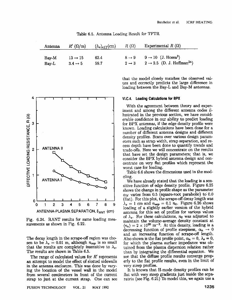
The decay length in the scrape-off region was cho- sen to be X, = 0.01 m, although nsep is so small that the results are completely insensitive to X,. The results are shown in Table 6.5.
The range of calculated values for R’ represents an attempt to model the effect of slotted sidewalls in the antenna enclosure. This was done by vary- ing the location of the vessel wall in the model from several centimeters in front of the current strap to just at the current strap. One can see
We have already stated that the loading is a sen- sitive function of edge density profile. Figure 6.25 shows the change in profile shape as the parameter (YN varies from 0.5 (square-root parabolic) to 0.0 (flat). For this plot, the scrape-off decay length was X, = 1 cm and nJep = 0.1 no. Figure 6.26 shows loading of a slightly earlier version of the hybrid antenna for this set of profiles for various values of X,. For these calculations, ne was adjusted to maintain the volume-average density constant at (n,) = 2 x 10²’ rne3. At this density, loading is a decreasing function of profile steepness, a, ---) 0 and an increasing function of scrape-off length. Also shown is the flat profile point, cu, = 0, X, = 0, for which the plasma surface impedance was ob- tained from the plasma dispersion relation rather than by integrating the differential equation. We see that the diffuse profile results converge prop erly to the flat profile results, even in the limit of very steep profiles.
It is known that H-mode density profiles can be flat with very steep gradients just inside the sepa- ratrix (see Fig. 6.21) To model this, we again use a
FUSION TECHNOLOGY VOL. 21 MAY 1992 1235
849 9 + 10 (J. Hosea3) 2+3 2 + 2.5 (D. J. Hoffman24)
that the model closely matches the observed val- ues and correctly predicts the large difference in loading between the Bay-L and Bay-M antennas.
VI.C.4. Loading Calculations for BPX
With the agreement between theory and exper- iment and among the different antenna codes il- lustrated in the previous section, we have consid- erable confidence in our ability to predict loading for BPX antennas, if the edge density profile were known. Loading calculations have been done for a number of different antenna designs and different density profiles. Scans over various design param- eters such as strap width, strap separation, and re- cess depth have been done to quantify trends and trade-offs. Here we will concentrate on the results that have set the design parameters; that is, we consider the BPX hybrid antenna design and con- centrate on very flat profiles which represent the worst case for loading.
Table 6.6 shows the dimensions used in the mod- eling.
Batchelor et al. ICRF HEATING
n, (R) FOR BPX (Raxis = 279 cm)
I I I I I
3 -
* 2- Z 7
X
l-
a
-0
- -0.1 ---- 0.2 ~-~~~~~ 0.3
- -- 0.4 -.-.-.- 0.5
0' I I I I
260 280 300 320 360 380 F’ (cm) 340
R sep = 338.5 ‘=‘,dge= 342.5
Fig. 6.25. Power-parabolic density profiles {- (1 - (T/T,,~)~]~} converging to flat (cu + 0) profile.
Parameters of Recessed Antenna Model Antenna a b d d, W, WC WA h, Hybrid 26.6 0.1 3.3 3 + 8 14.6 29.3 30.5 47.9
1236 FUSION TECHNOLOGY VOL. 21 MAY 1992
Batchelor et al. ICRF HEATING
20 6
18 5
16
2 9 (3 g l4
4
4
2 IB
1
- !
0 0 20 40 60 80 100
r
CEWISE LINEAR li = 2 ----B-v-
------------- PIECEWISE LINEAR ii = 1
FLAT PROFILE (LIMa-~0, h--,0)
81 0 0.1 0.2 0.3 0.4 0.5
a
Fig. 6.26. Antenna loading, R’, versus profile shape exponent, cr.
piecewise linear model, Fig. 6.27. We assume the location of the front of the antenna to be fixed rel- ative to the magnetic axis 7kdge. We vary d,, the separation between the front of the antenna and the separatrix, by adjusting rSep = T e - d,. And we adjust the steepness of the profile 3 y adjusting A = rdep - rb. The nominal antenna-separatrix spacing is d, = 0.04 m. A poloidal limiter extends radially to 0.01 m inside the Faraday shield. A belt limiter extends in an additional 0.01 m. The nom- inal separatrix position is 0.02 m inside the belt limiter.
Figures 6.28, 6.29, and 6.30 show loading for the hybrid antenna for a low-density case ((n,) = 1 x 1020 mm3), a nominal-density case ((n,) = 2.5 x 10²⁰ mS3), and a high-density case ((G) = 5 x 10²’ mS3), respectively. In all cases, the density at the separatrix is taken to be 10% of the peak density. The current straps are driven out of phase (dipole phasing). These results can be qualitatively under- stood by considering the two competing physical effects involved:
Fig. 6.27. Geometric parameters for piecewise lin- ear density profile used to model H-mode loading in Figs. 6.28, 6.29, and 6.30.
1. Increasing the plasma density near the an- tenna (increased X, or decreased dd) reduces the evanescence distance through which the waves must tunnel in order to propagate, thus increasing loading.
2. A steep density gradient in front of the antenna [increased %(Rg) or decreased A] presents an impedance mismatch which decreases cou- pling.
At low density (Fig. 6.28), the impedance mis- match is minimal so the main effect of increasing A (decreasing steepness) is to reduce the amount of nearby plasma and decrease coupling. At higher densities, the impedance mismatch is important so that increased A increases loading. However, mov- ing the density discontinuity closer to the current strap (smaller d,) decreases the tunneling distance and therefore increases loading at both high and low (n,).
It is of interest to compare these results with calculations obtained from the ORION two
FUSION TECHNOLOGY VOL. 21 MAY 1992 1237
Batchelor et al. ICRF HEATING
25
20
i5
2
g 10
2
5
0 I I I I I
0 1 2 3 4 5 6 6
Fig. 6.28. Loading for BPX hybrid antenna ver- sus A for various Faraday shield-to-separatrix sep- arations d, and scrape-off decay lengths X,: low- density case ((n,) = 1.0 x 10²⁰ me3).
dimensional code. The geometric parameters for the ORION calculations presented in Figs. 6.14, 6.13, and 6.16, correspond to ds = 4 cm, X, = 2 cm, and A = 5 cm, shown for the RANT model in Fig. 6.29. The ORION value for loading resis- tance is R’ = 19.34 n/m, obtained by dividing the total absorbed power by the 96-cm strap height and by 2 for the number of current straps. This is to be compared to the RANT value of 21 n/m. There are some differences in the two models that should be borne in mind in this comparison. The ORION code includes reflection at the fast-wave cutoff for low-$1 modes, which reduces loading rel- ative to RANT (which has purely outgoing wave boundary conditions). Image currents included in ORION in the walls at the top and bottom of the straps introduce some end effects, although the geometry at the end of the current straps is not an accurate representation of the actual design. This would also reduce loading relative to RANT. The finite poloidal length of the current straps is correctly included in ORION (higher poloidal modes are slightly more evanescent than the uni- form poloidal fields of RANT). The finite phase velocity effect is not included since the current was assumed uniform in the poloidal direction. Image currents in the side walls, which are correctly in- cluded in RANT, are absent in the ORION calcu- lations. This would tend to increase the ORION
1238 FUSION TECHNOLOGY VOL. 21 MAY 1992
loading relative to RANT. Altogether the agree- ment between codes seems quite good despite the differences in the models.
It is clear that the critical issue is loading at the highest volume-average density, with steep profiles (A - 0) and with very little plasma in the scrape- off layer. Therefore, the reference profile for speci- fication of the RF system is the worst case of a flat density profile, A = 0, with no scrape-off plasma, As = 0. We see from Fig. 6.30 that at the nomi- nal separatrix location, d, = 4 cm, the minimum loading is 8.6 Q/m. This is the basis for adopting a value of R’ = 8.6 0/m as the reference design value of load resistance. This value is further reduced by an end-effect factor of 0.92 as obtained by scaling from measurements on the TFTR antenna.
Note that the flat reference profile is in fact non- physical. If the density gradient just inside the sep- aratrix is not permitted to be infinite and if some plasma is assumed to be in the scrape-off layer, then predicted loadings are higher. For example, if the fall-off distance A is 2 cm and the scrape-off distance X, is 1 cm, then for the nominal limiter position, ds = 4 cm, the loading is 212 Q/m, a factor of 1.4 larger than the reference value.
As a further point of reference, the recessed an- tenna code ANTIMP, develo
P ed at the University
of Wisconsin, has been used 1 to consider a piece- wise linear density profile with a flat region in the center. This profile has the following parameters: n,(O) = 4 x 10m rnw3, G(TS) = 3 x 10²⁰ rnm3, fRF = 85 MHz, A = 1 cm, dS = 4 cm, and X, = 1 cm. Note that this density profile is a good fit to a parabolic profile with power expo nent cr = 0.25. As in RANT, the antenna is en- closed in a box of finite length in the toroidal di- rection, and ANTIMP explicitly takes into account finite
2 effects. With a uniform current in the
poloid direction, ANTIMP gives a loading resis- tance RL of 9.5 R for dipole phasing. Applying an end-effect correction factor of 0.92, we obtain (RL)RANT = 8.75 R for this case. Letting the pa- rameter A vary from 1 to 10 cm, the loading resis- tance changes from 9.5 to 17.6 R, respectively. A modified version of the Brambilla code2’ has also been used to study the variation of Rr, with respect to the wave phase velocity 21 along the strap. For a four-coaxial feed case (in w Ll ‘ch the current distri- bution does not greatly deviate from uniformity) and plasma parameters corresponding to BPX L and H modes, Rr, decreases by 18% as the phase velocity along the coil decreases from that procluc- ing a uniform current to 0.6 times the speed of light in vacuum.
Batchelor et al. ICRF HEATING
30
25
20
15
10
5
0
/’ -w--H 6 -4' -- *- - ---__---- _*--
I I 1 I 012345
A
hs=lcm I I 1 I
hs=2cm
--/- *--
_C-- --
---__*-
012345 012345 A A
Fig. 6.29. Loading for BPX hybrid antenna versus A for various Faraday shield-to-separatrix separations d, and scrape-off decay lengths X,. . intermediate-density case ((n,) = 1.0 x 10²’ m- ).
d,=3cm
012 3 4 5 A
h,=lcm I 1 1 I
hs=2cm 1 I I I
d,=3cm
d,=3cm
--I .- /*-----
*- *I -- _-- --
I I I I 1 I I I
012345 012345 A A
Fig. 6.30. Loading for BPX hybrid antenna versus A for various Farada? shield-to-separatrix separations d, and scrape-off decay lengths X,: high-density case ((n,) = 1.0 x 10 mS3).
FUSION TECHNOLOGY VOL. 21 MAY 1992 1239
Batchelor et al. ICRF HEATING
VI.C.5. Faraday Shield Design Issues
The Faraday shield is the final interface between the RF hardware and the plasma that is to be heated. Details of the plasma particle and energy fluxes in the scrape-off region along with RF losses control the heat load on the shield. These fluxes, together with the structure of RF near fields and RF-driven sheaths, determine the degree of local sputtering, impurity generation, and outgassing. Forces generated by induced currents during dis- ruption place severe constraints on Faraday shield design for survivability. In turn, the Faraday shield affects the plasma through its proclivity to gener- ate impurities, through its behavior as a limiter, and by its effect on the RF fields that ultimately must penetrate to the plasma.
There is a substantial base of empirical infor- mation on Faraday shield behavior in high-power tokamak experiments. Many designs have been tried, and data exist on the influence of blade size and shape, blade angle with respect to the mag- netic field, and structural and coating materials (see Ref. 25 for many relevant papers and addi- tional references). There is also beginning to be a base of physics understanding on Faraday shield effects in ICRF plasmas and in particular on how impurities are generated. Several mechanisms have been identified and investigated for the generation of enhanced sheath potentials due to RF fields.2G28
A model has been developed that has been quite successful in explaining observations of impurity influx on JET in terms of sputtering due to ion acceleration in the rectified direct current (DC) sheath potential. 2g This model, combined with ex- perience with various antenna designs, gives guid- ance as to the important variables for minimization of impurity influx. To the extent that impurity generation is a result of enhanced sheaths, the crit- ical element is to minimize the peak voltage of the RF-rectified sheaths. The sheath potential is lim- ited by line integral of the RF electric field along a magnetic field line that couples two grounded metal surfaces, such as two Faraday shield blades, of the front face of a Faraday shield blade and a limiter. This line integral is equal to the RF mag- netic flux linked by the magnetic field line, which is in turn proportional to the antenna strap cur- rent or strap voltage. It is therefore important to minimize the possible flux linkages by aligning the Faraday shield blades as nearly parallel to the toka- mak magnetic field as possible and by contouring the shield to the flux surfaces to minimize linkages to nearby limiters. Operation with two symmetric current 8traps, driven out of phase, also greatly re- duces the RF flux linked by magnetic field lines at the front face of the shield. Since at fixed radiated
1240
power the RF voltage is inversely proportional to the loading resistance, it is clear that high load- ing resistance is important for impurity control as well as for control of breakdown at the high-voltage points in the transmission system. Another impor- tant parameter is the plasma density at, and just in front of, the Faraday shield. This is because both the potential of the rectified sheath and the flux of sheath accelerated ions onto the surface increases with density.
Finally, it is clear that the materials used in the surfaces of Faraday shield elements and limiters is of critical importance. High-Z materials such as nickel, molybdenum, and tungsten are subject to high self-sputtering yield8 when sheath potentials exceed a few hundred volts. Fortunately, there ex- ist low-2 materials with the requisite thermal and mechanical properties to be usable in this environ- ment and that have sputtering yields for normal incidence less that 1 at all energies. Beryllium and graphite are in this category. Calculations by D’Ippolito et al.,,3o in a model that include8 ion acceleration in RF-enhanced sheaths, physi- cal sputtering, and scrape-off layer physics, have shown that amplification of neutral metal produc- tion by self-sputtering can lead to an avalanche phenomenon in high-2 surface materials, which is absent or significantly weaker with low-2 surface materials such as beryllium or carbon.
Another parameter that may be relevant because of its influence on the RF ponderomotive force on the plasma in front of the antenna is the RF power density in watts per square meter. The power den- sity for the BPX hybrid antenna at -8.5 W/m2 is substantially above that at which JET typically operates. However, it is comparable to the power densities achieved on TFTR and is well below the operating level of 12 MW/m* achieved on JT-60.
The BPX hybrid antenna system has been de- signed according to the above principles. Although design work for the BPX hybrid antenna Fara- day shield is ongoing, an idea of the present con- cept can be obtained from Figs. 6.17a, 6.17b, and 6.17~. A single tier of shield tubes is planned, the tubes being angled to align as closely as possi- ble with the magnetic field. The shield is to be constructed of copper-plated Inconel tubes with carbon-carbon composite tiles mechanically at- tached to the plasma side of the tubing (see inset, Fig. 6.17a). A single-tier design allows the current strap to be brought closer to the plasma than with a double-tier design, substantially increasing the antenna coupling. Furthermore, a more open de- sign with wider spacing between tubes results in an increase in magnetic flux transmission of ap- proximately 10%. The carbon-carbon composite has much higher electrical conductivity than con-
FUSION TECHNOLOGY VOL. 21 MAY 1992
Batchelor et al. ICRF HEATING
ventional graphite and allows smaller RF heating of the shield but has better thermal properties for disruption shocks than beryllium.
It must be made clear that the engineering dif- ficulties of designing a Faraday shield for BPX are severe. Heat loads from the plasma are large, and for certain materials, such as graphite, ohmic dis- sipation of the RF fields provides additional large heat loads. The shield must withstand large dis- ruption forces. Therefore, information from the new antennas on JET and those being constructed for TFTR, Alcator C-Mod, and JT-6OU will be monitored closely. Information coming from these experiments will be factored into the BPX design as it becomes available. A backup design will be considered along the lines of the JET wall-mounted antenna concept. This may permit more power to be launched per port or allow the power density in watts per cubic meter to be decreased at constant power. In addition, an array of uniformly spaced current straps could provide more control of the $1 spectrum for such purposes as current drive.
coupled into the most unfavorable density profile with moderate peak voltages in the RF system (32.5 kV). Careful attention has been paid to ex- perience gained in JET, TFTR, JT-60, PLT, and other high-power experiments to minimize break- down and impurity generation problems. This is an ongoing process, and new information on an- tenna and Faraday shield performance as well as materials properties will be incorporated as it be- comes available. It is also planned to do further investigation of design concepts other than the hy- brid, for example, a wall-mounted concept, in the spirit of the JET configuration.
ACKNOWLEDGMENTS
Research sponsored by the Office of Fusion En- ergy, U.S. Department of Energy, under contract DE-AC05-840R21400 with Martin Marietta En- ergy Systems, Inc.
VLC.6. Summary REFERENCES
ICRF appears to be ideally suited to heating the high-density plasmas of BPX. Present-day exper- iments have achieved the ICRF power levels re- quired for BPX and have achieved plasma param- eters approaching the BPX regime. The baseline heating scenario for BPX, 3He minority in D-T plasma, is similar to the D(3He) scenario that is routinely used in present experiments. A sizable base of experience now exists on a number of toka- maks, which permits confidence in extrapolation to the use of ICRF on BPX. Theoretical calculations, which have been found to be broadly consistent with experimental results, predict excellent heating for BPX plasmas. Although there is a significant amount of research, theory/experiment compari- son, and model development to be done in order to ensure optimum ICRJ? performance and to de- velop possibilities for alternative scenarios, there is no reason to doubt the success of ICRF in BPX.
Design of an ICRF system for BPX, particularly the launching structures, is a technological chal- lenge. Heat loads and disruption stresses are se- vere, and remote maintenance problems are dif- ficult. These factors have been analyzed and an antenna design obtained that meets the system design requirements (see the System Design De- scription for details). The launching efficiency of this design has been analyzed in detail, and consideration has been given to a wide. range of plasma density profiles that might be confronted. The design is conservative from a power radiation point of view, in that the required power can be
1. D. START, JET, Private Communication.
2. D. START et al., Pmt. 13th Int. Conf. on Plasma Physics and Controlled Nuclear fision Re- search, Washington, D.C., October 1-6, 1990, In- ternational Atomic Energy Agency (1990). 3. J. HOSEA et al., Proc. 13th Int. Conf. on Plasma Physics and Controlled Nuclear fision Re- search, Washington, D.C., October l-6, 1990, In- ternational Atomic Energy Agency (1990). 4. JET Team, Prvc. 11th Int. Conf. on Plasma Physics and Controlled Nuclear FZlsion Research, Kyoto, Japan, November 13-20, 1986, IAEA-CN- 47/F-I-l, p. 449, International Atomic Energy Agency (1986).
5. D. F. H. START et al., Proc. 12th Int. Conf. on Plasma Physics and Controlled Nuclear fision Re- search, Nice, France, October 12-19, 1988, IAEA- CN-50/E-11-3, p. 593, International Atomic Energy Agency (1988). 6. J. HOSEA et al., Proc. 8th Int. Conf. on Plasma Physics and Controlled Nuclear Fusion Research, Brussels, Belgium, July l-10, 1980, IAEA-CN- 38/D-5-1, Vol. II, p. 95, International Atomic En- ergy Agency (1980).
7. T. K. MAU and D. A. EHST, Bull. Am. Phys. Sot., 34, 1968 (1989). 8. E. F. JAEGER et al., Nucl. fision, 28, 1 (1988) and references contained therein.
FUSION TECHNOLOGY VOL. 21 MAY 1992 1241
Batchelor et al. ICRF HEATING
9. J. R. WILSON et al., Proc. 12th Int. Conf. on Plasma Physics and Controlled Nuclear fision Re- search, Nice, France, October 12-19, 1988, Inter- national Atomic Energy Agency (1988).
10. D. SMITHE et al., Phys. Rev. I&t., 60, 801 (1988).
11. E. F. JAEGER et al., Nucl. fision, 30, 505 (1990).
12. R. WHITE et al., Phys. Fluids B, 2, 745 (1990).
13. B. COPPI et al., Phys. Fluids B, 2,927 (1990).
14. J. ONGENA et al., Proc. of 17th European Conf on Controlled Fusion and Plasma Heating, Amsterdam, Netherlands, June 25-29, 1990, Vol. 14B, Part 1, p. 383, European Physical Society (1990).
15. F. PORCELLI et al., Proc. of 17th European Conf. on Controlled fision and Plasma Heating, Amsterdam, Netherlands, June 25-29, 1990, Vol. 14B, Part 1, p. 327, European Physical Society (1990).
16. J. HOSEA et al., Proc. of Joint Varenna- Lawanne Int. Workshop on Theo y of Fusion Plas- mas, Varenna, Italy, August 27-31, 1990.
17. D. J. CAMPBELL et al., Phys. Rev. Mt., 60, 2148 (1990).
18. R. GOULDING, ORNL, Private Communica- tion.
19. J. S. TOLLIVER and D. B. BATCHELOR, Bull. Am. Phys. Sot., 34, 2035 (1989).
20. M. BRAMBILLA, Nucl. F&ion, 28, 549 (1988). 21. J. E. SCHARER, N. T. LAM, M. BETTEN- HAUSEN, and J. RUFINUS, UW-CPTC Report 90-7, University of Wisconsin (1990).
22. M. MAYBERRY et al., Nucl. fision 30, 579 (1990).
23. S. C. CHIU, M. J. MAYBERRY and W. D. BARD, Nucl. I%sion, 30, 2551 (1990).
24. D. J. Hoffman, ORNL, Private Communica- tion, 1991.
25. J. M. NOTREDAEME and D. B. BATCHE- LOR, fision Eng. Design, 12 (1996). 26. F. W. PERKINS, Nucl. fision, 29, 583, (1989).
27. R. CHODURA, Fusion Eng. Design, 12, 111 (1990).
28. M. D. CARTER et al., fision Eng. Design, 12, 105 (1990)
29. J. R. MYRA, D. A. D’IPPOLITO, and M. J. GERVER, Nucl. fision, 30, 845, (1990).
30. D. A. D’IPPOLITO et al., “A Modelof Sheath- Driven Impurity Production by ICRF Antennas,” LRC-90-18, Lodestar Research Corp. (1990).