Proceedings of the5rd International Conference on Civil Structural and Transportation Engineering (ICCSTE'20) Niagara Falls, Canada Virtual Conference – November, 2020 Paper No. 272 DOI: 10.11159/iccste20.272 272-1 Vibration Induced By Rapid Impact Compaction on Granular Soils Omar El Khaled Trevi Arabian Soil Contractors Ltd. Al Khobar, Saudi Arabia [email protected]; Emmanouil Spyropoulos Saudi Aramco, Dhahran, Saudi Arabia. [email protected]; Omar Maalej Trevi ASC, Al Khobar, Saudi Arabia [email protected]; Abstract - The use of Rapid Impact Compaction (RIC), sometimes referred as Rapid Dynamic Compaction (RDC), has increased significantly in the latest years in Saudi Arabia mainly for large scale and strategic projects due to substantial time and cost saving benefits. Following the concept of Dynamic Compaction, RIC machines have been developed for the compaction of embankments and shallow treatment up to 6m depth, by providing a compaction hammer attached to a strengthened arm of a hydraulic excavator. This paper concludes the minimum required safe distance to prevent any potential damages of RIC on adjacent buildings and buried utilities, based on the results of experimental measurements supported by numerical model results. Keywords: Rapid Impact Compaction, Vibration Transmission, Safe Distance, Vibration Measurements. 1. Introduction 1.1. Preamble Rapid impact compaction (RIC) was developed in the late 1990s for the rapid repair of explosion damage to military airfield runways (Allen 1996; SAICE 2006; Serridge and Synac 2006). As an extension of the concept of weights dropped on the ground, RIC was developed using modified (BSP) hydraulic hammers acting on a steel foot that remains in contact with the ground. It improves the compacted soils by creating “a plug” of denser ground then driving this layer to greater depth, it is a top-down process. The development of RIC technique has closed the gap between superficial compaction techniques such as Roller compaction (RC) and High Energy Impact Compaction (HEIC), and deep improvement techniques such Deep Dynamic Compaction and Vibro Compaction. Though, despite all its advantages, the RIC technique, same as most of the heavy equipment, is generating a considerable ground vibration. 1.2. Motivation for this study and objective Rapid impact compaction (RIC) is currently used for many civilian applications, namely in GCC area. The application of RIC technique induces vibration waves that might be harmful for the surrounding vicinity of the working area as like building, structures, sensitive instrumentations and buried pipelines. As the RIC technique is relatively new, comprehensive studies should be initiated to further understand the possible dynamic effect of RIC on its environment. 1.3. Objective Numerical model and experimental analysis will be used to gain more knowledge about the vibration resulting from RIC application on poorly graded sand and silty sand material. In the first part of this study, details about the RIC rig and the work sequence are provided. Definition of peak velocity magnitude VR, max is provided in the second part with brief on the allowable peak velocity on buildings and buried utilities as per the British Standard BS 5228:2-2009 and Deutsche Norm DIN 4150-3 respectively.
Transcript
Proceedings of the5rd International Conference on Civil Structural and Transportation Engineering (ICCSTE'20)
Niagara Falls, Canada Virtual Conference – November, 2020
Paper No. 272
DOI: 10.11159/iccste20.272
272-1
Vibration Induced By Rapid Impact Compaction on Granular Soils
Omar El Khaled Trevi Arabian Soil Contractors Ltd.
Under normal working conditions, the hammer must be stopped when the recorded penetration is less than 25mm
for more than 10 blows, over 6 consecutive intervals of 25mm (For example 60 blows per 150mm).
272-3
2.2. RIC Applications
RIC technique has proven a high efficiency and excellent engineering performance for dry and/ or submerged granular
granular soils with less than 15% fine content passing sieve number #200. Less anticipated improvement occurred for soils
soils having significant silt content particularly below water table. RIC technique can be successfully used for the compaction
compaction of gravels, sands, reclaimed fills and landfills allowing the increase of allowable bearing capacity of foundations,
reducing the settlement and liquefaction potential of soils. RIC has been used as an alternative to the conventional soil
replacement solution.
RIC is a more cost-effective ground improvement solution comparing with the other techniques (SAICE 2006;
Kristiansen and Davies 2004). It has been used effectively in different civil engineering applications such as: Compacting
loose granular soils and miscellaneous fills (Allen 1996; Serridge and Synac 2006), Compacting granular backfill material
in lifts of 3m to 7m with the advanced models of RIC, Mitigating liquefaction potential ( Kristiansen and Davies 2003, 2004;
Serridge and Synac 2006) and reducing the collapse potential of metastable soils (Serridge and Synac 2006).
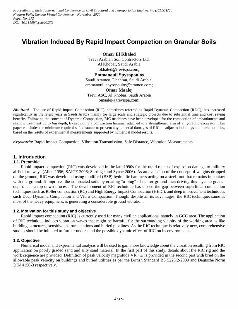
2.3. RIC Typical Work Sequence
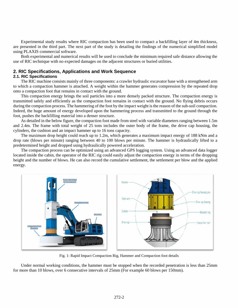
RIC works consists generally of two or three phases, namely Primary grid (Phase-1), Secondary grid (Phase-2) and
Tertiary grid (Phase-3). Typical final compaction grid (after all phases) is ranging between 2.5m to 5m. depending on the
grading plan, some projects might require that the top surface layer be compacted by the roller compactor after completing
the subject RIC works. The optimum grid for a specific project shall be determined based on the field trial, taking into
consideration the actual soil conditions and the required technical criteria. The below Figure-2 shows the typical square grid
used in the field trial performed for the purpose of this study.
Fig. 2: Typical RIC grid.
3. Vibration Definition, Limits and Factors for Response Analysis 3.1. Definition and factors for Buildings Response Analysis
The ground borne vibrations can be produced by variable construction activities such as piling, blasting or compaction.
It could be also generated by the moving vehicles on road and railways. The dynamic effects of such vibrations might create
some substantial problems for the surrounding structures. The RIC technique generates surfaces waves with frequencies
between 2 and 20 Hz. The dominant frequency of ground vibrations changes in the limits of 3-12 Hz (Mitchell 1981; Mayne
1985).
The surface waves referred as Rayleigh waves, propagating through energy-rich waves in the ground from the vibration
source to an adjacent building, buried utilities are the main vibrations to be studied in case of Rapid Impact compaction.
The amplitude of these waves decreases with distance increasing from the compaction point (RIC pounder is considered
as the source of vibration) due to the dissipation of energy in the soil itself.
(Optional)
272-4
According to the British Standard BS 5228-2:2009, the Peak particle velocity (PPV) is defined as an instantaneous
maximum velocity reached by a vibrating element as it oscillates about its rest position. The magnitudes of ground
are usually described in terms of PPV [mm/s].
The velocity is measured in three orthogonal directions namely Radial (x), Transverse (y) and Vertical (z). The peak
velocity magnitude VR,max [mm/s] during a single event is defined as the square root of the sum of the squares of the
corresponding velocity components Vx, Vy and Vz [Equation (1)].
VR,max = 2 2 2 |Vx Vy Vz max (1)
As per the British Standard BS 7385:2-1993, several factors could affect the response of a building to ground borne
vibration such as: the foundation type, the ground conditions and the interaction between both of them; The type of the
structure including its natural frequencies, mode, shape, and damping; The building individual components such as
floors, beams or ceilings and the structural system; Size and age of the building; Sensitivity of the building. 3.2. Allowable vibration velocity limits.
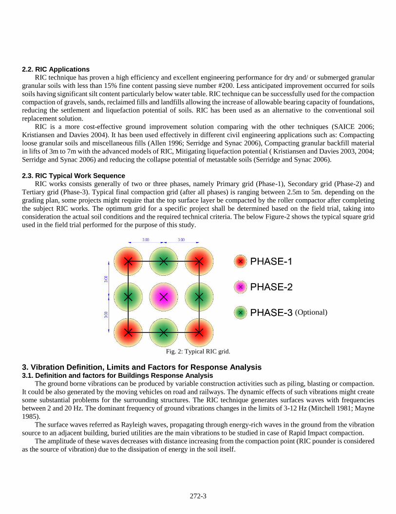
Threshold criteria for the limits of transient vibration above which superficial damage could occur, according to
the British Standard BS 5228-2:2009 are given in Table-1:
Table 1: Transient vibration guide values for cosmetic damage.
Line Type of Building
Peak component particle velocity in frequency range of
predominant pulse
4 Hz to 15 Hz 15 Hz and above
1 Reinforced or framed structures
Industrial and heavy commercial buildings 50 mm/s at 4 Hz and above
2 Unreinforced or light framed structures
Residential or light commercial buildings
15 mm/s at 4 Hz increasing
to 20 mm/s at 15 Hz
20 mm/s at 15 Hz increasing to
50 mm/s at 40 Hz and above
Note 1 Values referred to are at the base of the building
The Deutsche Norm DIN 4150-3 presents the allowable short-term vibration velocity limits on buried pipelines,
assuming that pipes has been manufactured and laid according the applicable regulations and standards.
Table 2: Guideline values for short-term vibration velocity on buried pipeline based on Deutsche Norm DIN 4150-3
4. Experimental Study of Vibration Induced by RIC 4.1. Trial Details and Device
A 16 Tons capacity RIC rig has been used to compact a trial test area with 4m backfilled material of poorly graded Sand
Sand and silty sand having a maximum fine content of less than 12%. The trial test area is located in Jubail – Kingdom of
of Saudi Arabia with 50mx100m dimensions. The site is an open area where no footings or utilities are located in the vicinity
vicinity allowing for safe vibration studies.
A heavy compaction energy using a 16 tons hammer dropped from a height of 0.7m and 40 blows per print has been
applied over three consecutive phases with a final square grid pattern of 3mx3m. The vibration measurements were taken
after each phase at variable distance, namely at 3m, 5m, 10m, 20m, 40m, 60m and 90m from the compaction point using a
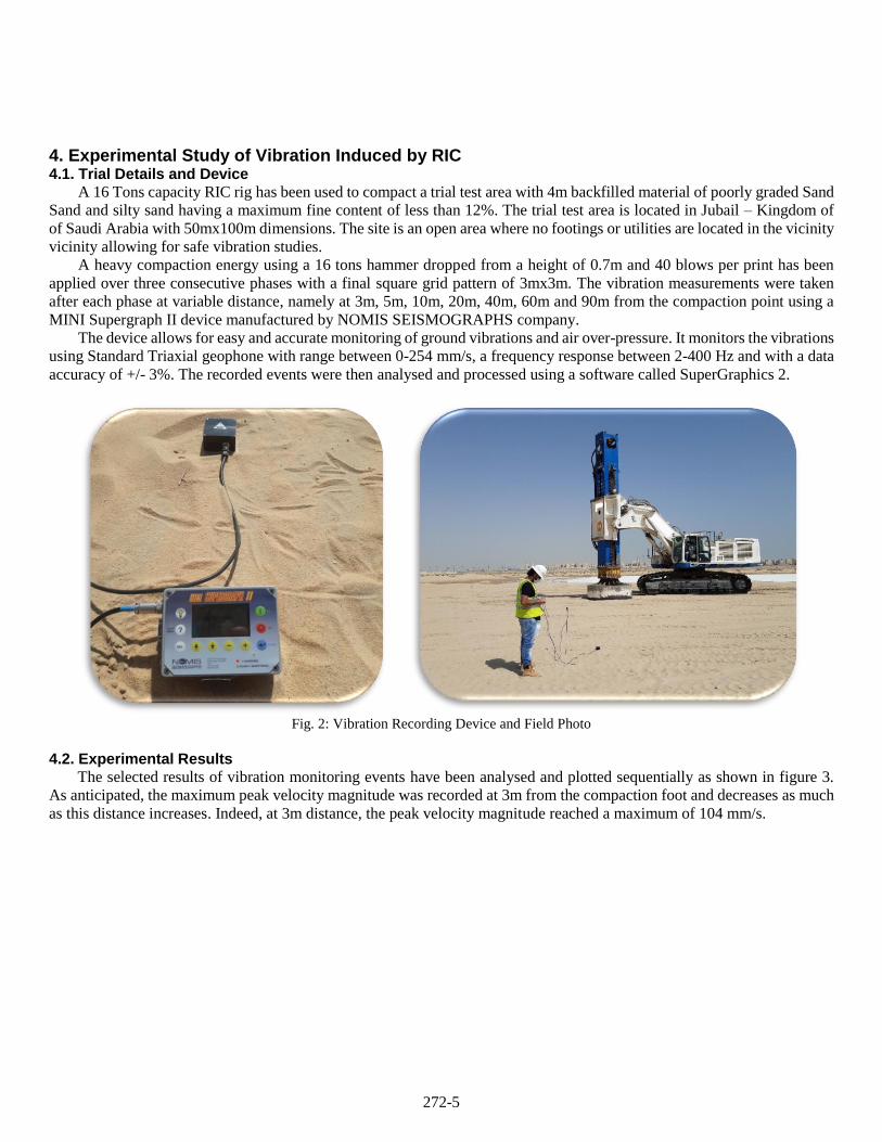
MINI Supergraph II device manufactured by NOMIS SEISMOGRAPHS company.
The device allows for easy and accurate monitoring of ground vibrations and air over-pressure. It monitors the vibrations
using Standard Triaxial geophone with range between 0-254 mm/s, a frequency response between 2-400 Hz and with a data
accuracy of +/- 3%. The recorded events were then analysed and processed using a software called SuperGraphics 2.
Fig. 2: Vibration Recording Device and Field Photo
4.2. Experimental Results
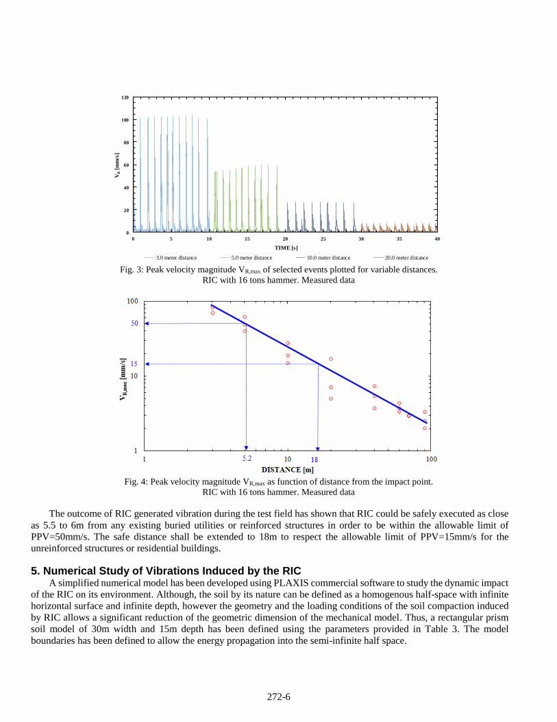
The selected results of vibration monitoring events have been analysed and plotted sequentially as shown in figure 3.
As anticipated, the maximum peak velocity magnitude was recorded at 3m from the compaction foot and decreases as much
as this distance increases. Indeed, at 3m distance, the peak velocity magnitude reached a maximum of 104 mm/s.
272-6
Fig. 3: Peak velocity magnitude VR,max of selected events plotted for variable distances.
RIC with 16 tons hammer. Measured data
Fig. 4: Peak velocity magnitude VR,max as function of distance from the impact point.
RIC with 16 tons hammer. Measured data
The outcome of RIC generated vibration during the test field has shown that RIC could be safely executed as close
as 5.5 to 6m from any existing buried utilities or reinforced structures in order to be within the allowable limit of
PPV=50mm/s. The safe distance shall be extended to 18m to respect the allowable limit of PPV=15mm/s for the
unreinforced structures or residential buildings.
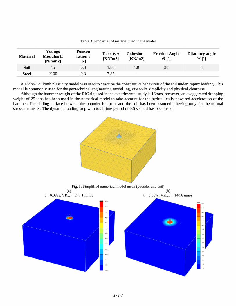
5. Numerical Study of Vibrations Induced by the RIC A simplified numerical model has been developed using PLAXIS commercial software to study the dynamic impact
of the RIC on its environment. Although, the soil by its nature can be defined as a homogenous half-space with infinite
horizontal surface and infinite depth, however the geometry and the loading conditions of the soil compaction induced
by RIC allows a significant reduction of the geometric dimension of the mechanical model. Thus, a rectangular prism
soil model of 30m width and 15m depth has been defined using the parameters provided in Table 3. The model
boundaries has been defined to allow the energy propagation into the semi-infinite half space.
0
20
40
60
80
100
120
0 5 10 15 20 25 30 35 40
VR
[mm
/s]
TIME [s]
3.0 meter distance 5.0 meter distance 10.0 meter distance 20.0 meter distance
272-7
Table 3: Properties of material used in the model
Material
Youngs
Modulus E
[N/mm2]
Poisson
ration ν
[-]
Density γ
[KN/m3]
Cohesion c
[KN/m2]
Friction Angle
Ø [°] Dilatancy angle
Ψ [°]
Soil 15 0.3 1.80 1.0 28 8
Steel 2100 0.3 7.85 - - -
A Mohr-Coulomb plasticity model was used to describe the constitutive behaviour of the soil under impact loading. This
model is commonly used for the geotechnical engineering modelling, due to its simplicity and physical clearness.
Although the hammer weight of the RIC rig used in the experimental study is 16tons, however, an exaggerated dropping
weight of 25 tons has been used in the numerical model to take account for the hydraulically powered acceleration of the
hammer. The sliding surface between the pounder footprint and the soil has been assumed allowing only for the normal
stresses transfer. The dynamic loading step with total time period of 0.5 second has been used.
Fig. 5: Simplified numerical model mesh (pounder and soil)
(a)
t = 0.033s, VRmax =247.1 mm/s
(b)
t = 0.067s, VRmax = 140.6 mm/s
272-8
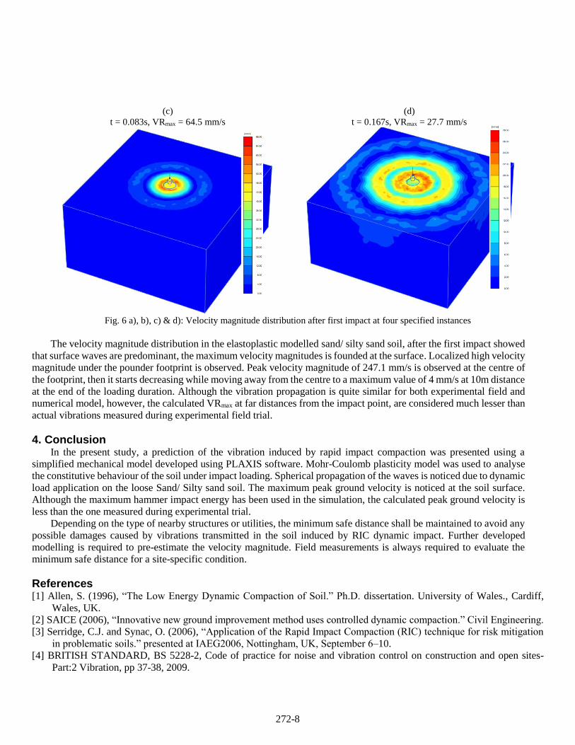
(c)
t = 0.083s, VRmax = 64.5 mm/s
(d)
t = 0.167s, VRmax = 27.7 mm/s
Fig. 6 a), b), c) & d): Velocity magnitude distribution after first impact at four specified instances
The velocity magnitude distribution in the elastoplastic modelled sand/ silty sand soil, after the first impact showed
that surface waves are predominant, the maximum velocity magnitudes is founded at the surface. Localized high velocity
magnitude under the pounder footprint is observed. Peak velocity magnitude of 247.1 mm/s is observed at the centre of
the footprint, then it starts decreasing while moving away from the centre to a maximum value of 4 mm/s at 10m distance
at the end of the loading duration. Although the vibration propagation is quite similar for both experimental field and
numerical model, however, the calculated VRmax at far distances from the impact point, are considered much lesser than
actual vibrations measured during experimental field trial.
4. Conclusion In the present study, a prediction of the vibration induced by rapid impact compaction was presented using a
simplified mechanical model developed using PLAXIS software. Mohr-Coulomb plasticity model was used to analyse
the constitutive behaviour of the soil under impact loading. Spherical propagation of the waves is noticed due to dynamic
load application on the loose Sand/ Silty sand soil. The maximum peak ground velocity is noticed at the soil surface.
Although the maximum hammer impact energy has been used in the simulation, the calculated peak ground velocity is
less than the one measured during experimental trial.
Depending on the type of nearby structures or utilities, the minimum safe distance shall be maintained to avoid any
possible damages caused by vibrations transmitted in the soil induced by RIC dynamic impact. Further developed
modelling is required to pre-estimate the velocity magnitude. Field measurements is always required to evaluate the
minimum safe distance for a site-specific condition.
References [1] Allen, S. (1996), “The Low Energy Dynamic Compaction of Soil.” Ph.D. dissertation. University of Wales., Cardiff,