Vibration reduction for flexible systems by command smoothing Xumiao Xie, Jie Huang n , Zan Liang School of Mechanical Engineering, Beijing Institute of Technology, Beijing 100081, China article info Article history: Received 5 September 2012 Received in revised form 20 December 2012 Accepted 25 February 2013 Keywords: Command smoothing Flexible system Vibration reduction Input shaping Modeling error abstract A method is presented for limiting vibration in flexible systems by smoothing the original command. The original command is smoothed to drive the flexible systems without inducing vibration. The proposed smoother is designed as a function of system natural frequency and damping ratio. The comparison between the new method and the zero vibration and triple derivative (ZVDDD) shaper for modeling error is explored and quantified. The theoretic analysis shows that the new method is more insensitive at higher frequencies, while the ZVDDD shaper has more insensitivity at lower frequencies. Moreover, the designed smoother benefits vibration reduction for multi-mode systems. Experimental results for single-mode and multi-mode systems validate the simulated dynamic behavior and the effectiveness of the new method. & 2013 Elsevier Ltd. All rights reserved. 1. Introduction Flexible dynamic systems suffer from unwanted transient deflection and residual vibration. Those detrimental effects cause significant problems for positioning accuracy, effectiveness, fatigue and safety for many types of systems ranging from nano-positioning devices to large industrial cranes [1]. Therefore, there exists a need for a control system that can effectively reduce vibration. Numerous researchers have worked to provide solutions to the challenging problems posed by the flexible dynamic systems. The work can roughly be broken into three categories: feedback control, input shaping and command smoothing. The feedback control strategies use measurements and estimation of system state to suppress vibration. Qiu designed an adaptive nonlinear controller for vibration reduction. The gains of the controller were varied with the vibration amplitude. The performance of the controller was verified on a flexible Cartesian manipulator [2]. Yu et al. proposed a robust controller for vibration suppression of rotor systems supported by magnetic bearings. Simulations demonstrated the effectiveness of the controller and its robustness to uncertainties, such as sudden disk mass loss and speed variation [3]. Input shaping can effectively reduce the oscillatory dynamics of many types of flexible dynamic systems including bridge cranes [4], tower cranes [5], boom cranes [6], container cranes [7], coordinate measurement machines [8], spacecrafts [9], robotic arms [10], robotic workcells [11], demining robots [12], micro-milling machines [13], nano- positioning stages [14], and linear step motors [15]. The input shaping process is demonstrated as follows. The original command produces an oscillatory response. To eliminate the oscillatory response, the original command is convolved with a series of impulses, called the input shaper, to create the shaped command. The shaped command can move the system without inducing vibrations. For a three-impulse zero vibration and derivative (ZVD) shaper, the amplitudes, A i , and times, Contents lists available at SciVerse ScienceDirect journal homepage: www.elsevier.com/locate/ymssp Mechanical Systems and Signal Processing 0888-3270/$ - see front matter & 2013 Elsevier Ltd. All rights reserved. http://dx.doi.org/10.1016/j.ymssp.2013.02.021 n Corresponding author. Tel.: þ86 1068915097. E-mail address: [email protected] (J. Huang). Mechanical Systems and Signal Processing ] (]]]]) ]]]–]]] Please cite this article as: X. Xie, et al., Vibration reduction for flexible systems by command smoothing, Mech. Syst. Signal Process. (2013), http://dx.doi.org/10.1016/j.ymssp.2013.02.021i
Transcript
Contents lists available at SciVerse ScienceDirect
Mechanical Systems and Signal Processing
Mechanical Systems and Signal Processing ] (]]]]) ]]]–]]]
0888-32
http://d
n Corr
E-m
PleasSign
journal homepage: www.elsevier.com/locate/ymssp
Vibration reduction for flexible systemsby command smoothing
Xumiao Xie, Jie Huang n, Zan Liang
School of Mechanical Engineering, Beijing Institute of Technology, Beijing 100081, China
e cite this article as: X. Xie, et al.,al Process. (2013), http://dx.doi.org
a b s t r a c t
A method is presented for limiting vibration in flexible systems by smoothing the
original command. The original command is smoothed to drive the flexible systems
without inducing vibration. The proposed smoother is designed as a function of system
natural frequency and damping ratio. The comparison between the new method and the
zero vibration and triple derivative (ZVDDD) shaper for modeling error is explored and
quantified. The theoretic analysis shows that the new method is more insensitive at
higher frequencies, while the ZVDDD shaper has more insensitivity at lower frequencies.
Moreover, the designed smoother benefits vibration reduction for multi-mode systems.
Experimental results for single-mode and multi-mode systems validate the simulated
dynamic behavior and the effectiveness of the new method.
& 2013 Elsevier Ltd. All rights reserved.
1. Introduction
Flexible dynamic systems suffer from unwanted transient deflection and residual vibration. Those detrimental effectscause significant problems for positioning accuracy, effectiveness, fatigue and safety for many types of systems rangingfrom nano-positioning devices to large industrial cranes [1]. Therefore, there exists a need for a control system that caneffectively reduce vibration.
Numerous researchers have worked to provide solutions to the challenging problems posed by the flexible dynamicsystems. The work can roughly be broken into three categories: feedback control, input shaping and command smoothing.The feedback control strategies use measurements and estimation of system state to suppress vibration. Qiu designed anadaptive nonlinear controller for vibration reduction. The gains of the controller were varied with the vibration amplitude.The performance of the controller was verified on a flexible Cartesian manipulator [2]. Yu et al. proposed a robustcontroller for vibration suppression of rotor systems supported by magnetic bearings. Simulations demonstrated theeffectiveness of the controller and its robustness to uncertainties, such as sudden disk mass loss and speed variation [3].
Input shaping can effectively reduce the oscillatory dynamics of many types of flexible dynamic systems includingbridge cranes [4], tower cranes [5], boom cranes [6], container cranes [7], coordinate measurement machines [8],spacecrafts [9], robotic arms [10], robotic workcells [11], demining robots [12], micro-milling machines [13], nano-positioning stages [14], and linear step motors [15]. The input shaping process is demonstrated as follows. The originalcommand produces an oscillatory response. To eliminate the oscillatory response, the original command is convolved witha series of impulses, called the input shaper, to create the shaped command. The shaped command can move the systemwithout inducing vibrations. For a three-impulse zero vibration and derivative (ZVD) shaper, the amplitudes, Ai, and times,
All rights reserved.
g).
Vibration reduction for flexible systems by command smoothing, Mech. Syst./10.1016/j.ymssp.2013.02.021i
X. Xie et al. / Mechanical Systems and Signal Processing ] (]]]]) ]]]–]]]2
ti, of the impulses are given by [10]
Ai
ti
� �¼
11þ2KþK2
2K1þ2KþK2
K2
1þ2KþK2
0 0:5Td Td
" #ð1Þ
where Td is the damped period of vibration and K is given by
K ¼ eð�zp=ffiffiffiffiffiffiffiffi1�z2p
Þ ð2Þ
where z is the damping ratio. The convolution is performed by simply multiplying the original command by the amplitudeof the first impulse, and adding it to the original command multiplied by the amplitude of the second impulse and shiftedin time by one-half of the damped vibration period, and then adding it to the original command multiplied by theamplitude of the third impulse and shifted in time by a damped vibration period. Note that the rise time of the shapedcommand is increased by the duration of the input shaper.
There have been hundreds of papers on smooth command profiles to drive flexible systems and reduce vibration, suchas S-curves [16], trigonometric transition functions [17], Gaussians [18], spline function [19] and cam polynomials [20].Smooth profiles have been used to reduce the tendency to excite flexible system vibration. The trajectory ramps up to peakacceleration and ramps down to constant velocity, thereby producing a smooth velocity profile. The smooth transitionsbetween boundary conditions avoid vibration. Note that vibration suppression comes at the cost of increased duration ofthis ramp-up time.
While significant work has been directed at smooth profiles to reduce vibration, however, these methods usually failto fully exploit the known properties of the system. Instead, they simply provide a low-pass filtering effect [21].The contribution of this paper is a novel method for command smoothing in order to limit the residual vibrations.The proposed smoother is a function of the system parameters, such as natural frequency and damping ratio. An increasein robustness to modeling errors in natural frequency and damping must be traded off against an increase in rise time.However, the robustness for a given rise time will differ between design methods. Therefore, an effective method forvibration reduction should provide the optimal robustness for a given rise time. Note that the proposed smoother can onlyreduce the vibration induced by intentional motions commanded by the human operator. However, it cannot rejectexternal disturbances.
The rest of this paper is organized as follows. The Section 2 presents the design of the smoother for vibration reduction.In Section 3, the comparison between the smoother and the zero vibration and triple derivative (ZVDDD) shaper formodeling error in natural frequency and damping ratio is investigated. The higher-order derivative smoother, whichincreases the robustness, is presented in Section 4. Section 5 demonstrates the effectiveness of the new method on singlependulum and double pendulum crane.
2. Design of command smoothing for vibration reduction
The command smoothing is a control method that dramatically suppresses motion-induced vibration by intelligentlysmoothing the original command. Using estimates of system natural frequency and damping ratio, the smoother isdesigned.
If the system can be modeled as a second-order harmonic oscillator, then the system response from the smoothedimpulse command, u, is
If Eqs. (5) and (6) are limited to zero, the smoothed impulse command, u, would cause no residual vibration. In order toadd the robustness of the smoother under variations of the system natural frequency and damping ratio, a new constraintmust be added. The derivative of Eqs. (5) and (6) with respect to o and z can also be set equal to zero [10]. Changes in
Please cite this article as: X. Xie, et al., Vibration reduction for flexible systems by command smoothing, Mech. Syst.Signal Process. (2013), http://dx.doi.org/10.1016/j.ymssp.2013.02.021i
X. Xie et al. / Mechanical Systems and Signal Processing ] (]]]]) ]]]–]]] 3
natural frequency and damping ratio will cause small changes in vibration amplitude. To satisfy this requirement, thefollowing equations should be applied:Z þ1
Another constraint must be applied to ensure that the smoothed command reaches the same set-point as the originalcommand. To satisfy this requirement, the integral of the smoothed impulse command, u, is limited to oneZ þ1
t ¼ 0uðtÞdt¼ 1 ð9Þ
while limiting Eqs. (5) and (6) to zero and from Eqs. (7–9), the smoothed impulse command is described by
uðtÞ ¼tu0e�zmomt, 0rtrTm
ð2Tm�tÞu0e�zmomt, Tmotr2Tm
0 t42Tm
8><>:
9>=>; ð10Þ
where om is the modeled natural frequency, zm is the modeled damping ratio, Tm is the modeled damped oscillationperiod, and u0 is the smoothed impulse command at time zero. From Eqs. (9) and (10), it has the form
u0 ¼z2
mo2m
ð1�MÞ2ð11Þ
where
M¼ e�2pzm=ffiffiffiffiffiffiffiffiffi1�z2
m
pð12Þ
Fig. 1 shows the smoothed impulse curve, which is a piecewise continuous profile as a function of natural frequencyand damping ratio. From Eq. (10), the transfer function of the smoother is:
smootherðsÞ ¼z2
mo2m
ð1�MÞ2Uð1�Me�TmsÞ
2
ðsþzmomÞ2
ð13Þ
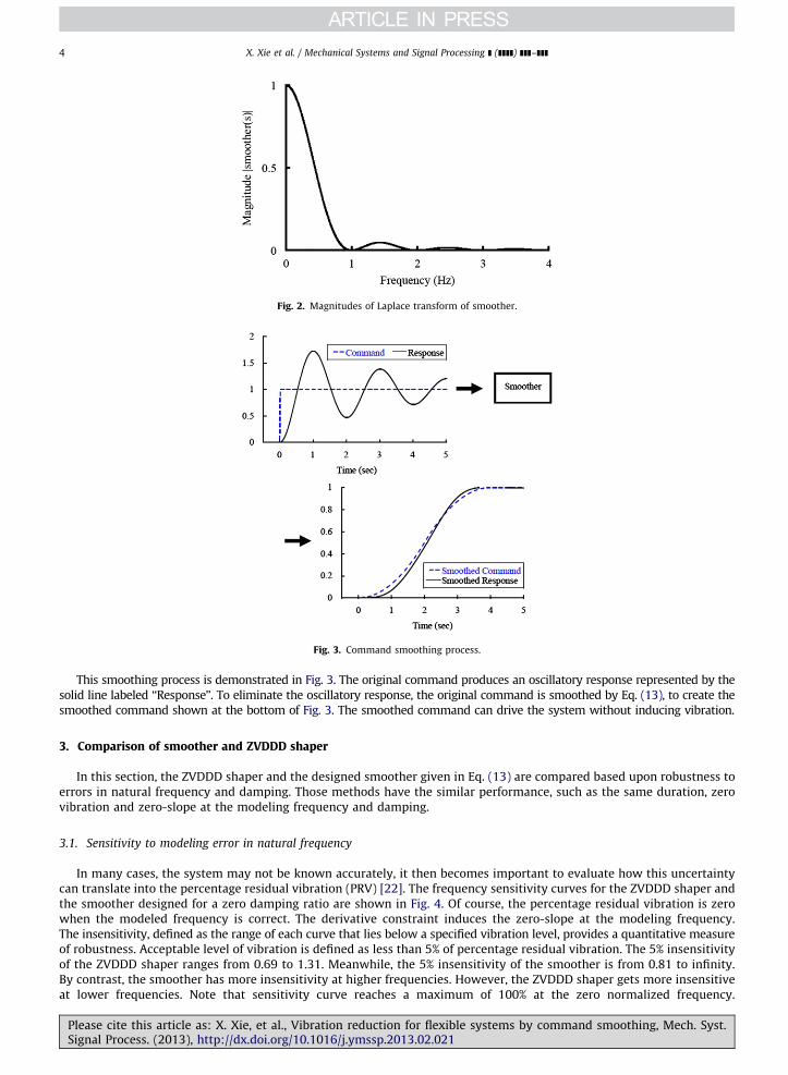
Using the smoother Eq. (13), the vibration amplitude Eq. (4) will be limited to zero for any arbitrary command when themodeled frequency and damping ratio are correct. Fig. 2 shows the magnitudes of the smoother Eq. (13) for a modeleddamped natural frequency of 1 Hz. It is clear that the smoother is a combination of low-pass and multi-notch filters.According to Fig. 2, the smoothed command cannot excite systems which have modes corresponding to the notchfrequencies at 1, 2, 3 Hz, etc. It is also apparent that high frequencies will not be excited by the smoothed command.The magnitude of the smoother is equal to one at the zero frequency so that the smoothing process is to have unity gain.
The smoothing process increases the rise time by the duration of the smoother Eq. (13). The duration of the smootherEq. (13), RSM, is twice as long as a modeled damped vibration period:
RSM ¼ 2Tm ð14Þ
Fig. 1. Smoothed impulse command as a function of system parameters.
Please cite this article as: X. Xie, et al., Vibration reduction for flexible systems by command smoothing, Mech. Syst.Signal Process. (2013), http://dx.doi.org/10.1016/j.ymssp.2013.02.021i
Fig. 2. Magnitudes of Laplace transform of smoother.
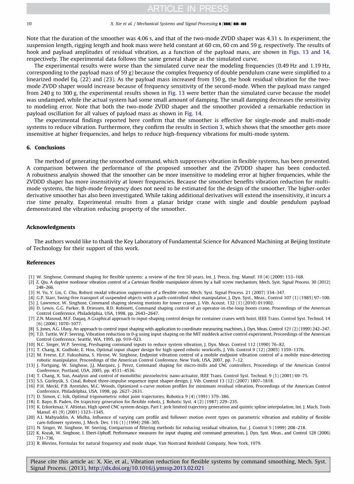
Fig. 3. Command smoothing process.
X. Xie et al. / Mechanical Systems and Signal Processing ] (]]]]) ]]]–]]]4
This smoothing process is demonstrated in Fig. 3. The original command produces an oscillatory response represented by thesolid line labeled ‘‘Response’’. To eliminate the oscillatory response, the original command is smoothed by Eq. (13), to create thesmoothed command shown at the bottom of Fig. 3. The smoothed command can drive the system without inducing vibration.
3. Comparison of smoother and ZVDDD shaper
In this section, the ZVDDD shaper and the designed smoother given in Eq. (13) are compared based upon robustness toerrors in natural frequency and damping. Those methods have the similar performance, such as the same duration, zerovibration and zero-slope at the modeling frequency and damping.
3.1. Sensitivity to modeling error in natural frequency
In many cases, the system may not be known accurately, it then becomes important to evaluate how this uncertaintycan translate into the percentage residual vibration (PRV) [22]. The frequency sensitivity curves for the ZVDDD shaper andthe smoother designed for a zero damping ratio are shown in Fig. 4. Of course, the percentage residual vibration is zerowhen the modeled frequency is correct. The derivative constraint induces the zero-slope at the modeling frequency.The insensitivity, defined as the range of each curve that lies below a specified vibration level, provides a quantitative measureof robustness. Acceptable level of vibration is defined as less than 5% of percentage residual vibration. The 5% insensitivityof the ZVDDD shaper ranges from 0.69 to 1.31. Meanwhile, the 5% insensitivity of the smoother is from 0.81 to infinity.By contrast, the smoother has more insensitivity at higher frequencies. However, the ZVDDD shaper gets more insensitiveat lower frequencies. Note that sensitivity curve reaches a maximum of 100% at the zero normalized frequency.
Please cite this article as: X. Xie, et al., Vibration reduction for flexible systems by command smoothing, Mech. Syst.Signal Process. (2013), http://dx.doi.org/10.1016/j.ymssp.2013.02.021i
Fig. 4. Frequency sensitivity for smoother and ZVDDD shaper.
Fig. 5. Damping sensitivity for smoother and ZVDDD shaper (zm¼0.1).
X. Xie et al. / Mechanical Systems and Signal Processing ] (]]]]) ]]]–]]] 5
The percentage residual vibration for the ZVDDD shaper at the even normalized frequencies is also 100%. Increasingnormalized frequency will decrease the peak of percentage residual vibration for the smoother, thereby reducing high-frequency vibrations. This performance will benefit vibration reduction for multi-mode systems. If the smoother isdesigned to eliminate vibration of low-mode frequency, it will also suppress that of high-mode frequency. Thus, the high-mode frequency does not need to be estimated for the design of the smoother.
3.2. Sensitivity to modeling error in damping
The damping sensitivity curves for the ZVDDD shaper and the smoother designed for a modeled damping ratio of 0.1are shown in Fig. 5. The robustness to errors in damping follows similar trends to robustness to changes in frequency. Onedifference is that damping ratio is not normalized. That is because when the modeled damping ratio is near zero, smallchanges in damping result in large changes in the normalized damping ratio. The percentage residual vibration is also zerowhen the modeled damping ratio is correct. The derivative constraint also induces the zero-slope at the modeling dampingratio. The smoother and ZVDDD shaper provide a dramatic reduction in percentage residual vibration for all valuesof damping shown in Fig. 5. Note that extremely large variations in damping are tolerated. Changes in damping do not havea large effect on the vibration as changes in frequency.
4. Higher-order derivative smoother
The process of adding robustness can be further extended to include the higher-order derivatives of Eqs. (5) and (6)with respect to o and z [10]. The general form of limiting the nth derivatives of Eqs. (5) and (6) with respect to o and zto zero isZ þ1
t ¼ 0tnuðtÞezotsinðot
ffiffiffiffiffiffiffiffiffiffiffiffi1�z2
qÞdt¼ 0 ð15Þ
Please cite this article as: X. Xie, et al., Vibration reduction for flexible systems by command smoothing, Mech. Syst.Signal Process. (2013), http://dx.doi.org/10.1016/j.ymssp.2013.02.021i
while limiting Eqs. (5) and (6) to zero and from (9), (15) and (16), the transfer function of the smoother with the nthderivative (SMnD) with respect to o and z is described by
SMnDðsÞ ¼zðnþ1Þ
m oðnþ1Þm
ð1�MÞðnþ1Þ
ð1�Me�TmsÞðnþ1Þ
ðsþzmomÞðnþ1Þ
ð17Þ
The duration of (17), RSMnD, is (nþ1) times as long as a modeled damped vibration period
RSMnD ¼ ðnþ1ÞTm ð18Þ
The frequency sensitivity curves for the smoother, the smoother with the second derivative, and the smoother with thethird derivative, designed for a zero damping ratio are shown in Fig. 6. The 5% frequency insensitivity of the smootherranges from 0.81 to infinity, and that with the second derivative is from 0.7 to infinity, and that with the third derivativevaries from 0.63 to infinity. Therefore, the frequency insensitivity will increase by taking additional derivatives.
The damping sensitivity curves for the smoother, the smoother with the second derivative, and the smoother with thethird derivative, designed for a modeled damping ratio of 0.1 are shown in Fig. 7. The damping insensitivity will alsoincrease by taking additional derivatives. The price for each additional derivative is an increase in smoothing duration by amodeled damped oscillation period.
5. Experimental results
To verify some of the key theoretical results mentioned above, experiments were performed on a planar bridge cranewith single pendulum and double pendulum payload, which correspond to single-mode and two-mode systems,respectively.
Please cite this article as: X. Xie, et al., Vibration reduction for flexible systems by command smoothing, Mech. Syst.Signal Process. (2013), http://dx.doi.org/10.1016/j.ymssp.2013.02.021i
Fig. 9. Residual vibration on a single pendulum crane.
X. Xie et al. / Mechanical Systems and Signal Processing ] (]]]]) ]]]–]]] 7
5.1. Single pendulum crane
A planar single pendulum bridge crane can be modeled as a single pendulum on a trolley, which is shown in Fig. 8.The generalized displacements are the position of the trolley and the angular deflection of the payload. The trolley ismodeled as a mass with an applied actuator force. A tennis ball was served as the payload, which was suspended from arigid and weightless cable. It is assumed that the motion of the trolley is unaffected by motion of the payload due to thelarge mechanical impedance in the drive system, and the suspension cable length does not change during the motion.
Using the well-known pendulum relationship between the payload suspension length, l, the gravitational constant,g, and the natural frequency, we know that the natural frequency of pendulum oscillation is
o¼ffiffiffig
l
rð19Þ
Of course, the length of a crane suspension cable cannot be known with total accuracy, so it is of interest to investigate theresidual vibration with various size errors in the estimation of the suspension length. A series of experiments wereperformed by using the smoother and the ZVDDD shaper to move payloads with various suspension lengths when themodeled suspension length was 100 cm. The experimental and simulated amplitudes of residual vibration, as a function ofthe suspension length, are shown in Fig. 9. The suspension cable length varied from 40 cm to 160 cm, which corresponds tofrequencies from 0.39 Hz to 0.79 Hz. The experimental data follows the same general shape as the simulated curve.The smoother and the ZVDDD shaper eliminated oscillations near the modeling frequency (0.50 Hz, corresponding tosuspension length of 100 cm). Then, as the suspension length increased from 100 cm, the residual amplitude for thesmoother would increase faster because of more insensitivity at lower frequencies for the ZVDDD shaper. Meanwhile, asthe suspension length decreased from 100 cm, the residual amplitude for the ZVDDD shaper would increase sharplybetween 40 cm and 60 cm because of more insensitivity at higher frequencies for the smoother.
Fig. 10 shows the effect when the ZVDDD shaper and the smoother were used to move the trolley 48 cm. The originalcommand was a trapezoidal velocity profile. The ZVDDD-shaped command performed in this experiment induced jerks
Please cite this article as: X. Xie, et al., Vibration reduction for flexible systems by command smoothing, Mech. Syst.Signal Process. (2013), http://dx.doi.org/10.1016/j.ymssp.2013.02.021i
Fig. 10. Trolley response to ZVDDD-shaped and smoothed command.
Fig. 11. A planar double-pendulum bridge crane.
X. Xie et al. / Mechanical Systems and Signal Processing ] (]]]]) ]]]–]]]8
at time 0 s, 1 s, 2 s, 3 s, 4 s and 5 s. In this case, the smoothed command was an S-curve profile, which had smoothtransitions between boundary conditions.
5.2. Double pendulum crane
Fig. 11 is a schematic representation of a planar double-pendulum bridge crane. The crane is moved by applying a forceto the trolley. The suspension cable of length, lh, hangs below the trolley and supports a hook of mass, mh, to which thepayload is attached using rigging cable. Hence, the rigging cable and payload are modeled as a second cable, of length, lp,and point mass, mp. Assuming the suspension and rigging lengths do not change, the linearized equations of motions are:
ah
dd¼�
g
lhahþ
gR
lhap�
aðtÞ
lhð20Þ
apdd¼
g
lhah�
g
lpþ
gR
lpþ
gR
lh
� �apþ
aðtÞ
lhð21Þ
where ah and ap are swing angle of the hook and payload, R is the ratio of the payload mass to the hook mass, and a(t) isthe acceleration of the trolley. Then, the linearized frequencies of the planar double-pendulum bridge crane dynamicsmodeled in the Eqs. (20) and (21) are [23]
o1,2 ¼
ffiffiffig
2
r ffiffiffiffiffiffiffiffiffiffiffiffiffiffiffiffiffiffiffiffiffiffiffiffiffiffiffiffiffiffiffiffiffiffiffiffiffiffiffiffiffiffiffið1þRÞ
The frequencies depend on the two cable lengths and the mass ratio. Fig. 12 shows the two frequencies as a function ofpayload mass ranged from 50 g to 300 g when the suspension length, rigging length and hook mass were held constant at60 cm, 60 cm and 59 g, respectively. The first-mode frequencies varied from 0.47 Hz to 0.50 Hz, while the second-modefrequencies ranged from 1.13 Hz to 2.20 Hz. Such information can be used to design two-mode input shaper and smoother.
Please cite this article as: X. Xie, et al., Vibration reduction for flexible systems by command smoothing, Mech. Syst.Signal Process. (2013), http://dx.doi.org/10.1016/j.ymssp.2013.02.021i
X. Xie et al. / Mechanical Systems and Signal Processing ] (]]]]) ]]]–]]] 9
The input shaper can easily be generalized to handle multi-mode systems. If an input shaper is designed for each of the twomode of a system independently, they can be convolved together to form a two-mode input shaper which drives the two-modesystem without vibration. The rise time of the resulting two-mode shaper is the sum of the duration of the individual shaper.
The smoother helps to reduce high-frequency vibrations for multi-mode systems. Because the first-mode smoother willalso eliminate vibration at second-mode frequency, the designer does not need to estimate the second-mode frequency.However, the first-mode frequency is necessary for the design of a smoother. For the modeled payload mass of 59 g, thesmoother for the double pendulum crane is
smootherðsÞ ¼ð1�2e�2:03sþe�4:06sÞ
4:1221s2ð24Þ
A series of experiments were performed by using the smoother and the two-mode zero vibration and double derivative(ZVDD) shaper to move a double pendulum crane with various payload mass when the modeled payload mass was 59 g.
Fig. 12. Variation of first and second mode frequencies.
Fig. 13. Hook residual vibration on a double pendulum crane.
Fig. 14. Payload residual vibration on a double pendulum crane.
Please cite this article as: X. Xie, et al., Vibration reduction for flexible systems by command smoothing, Mech. Syst.Signal Process. (2013), http://dx.doi.org/10.1016/j.ymssp.2013.02.021i
X. Xie et al. / Mechanical Systems and Signal Processing ] (]]]]) ]]]–]]]10
Note that the duration of the smoother was 4.06 s, and that of the two-mode ZVDD shaper was 4.31 s. In experiment, thesuspension length, rigging length and hook mass were held constant at 60 cm, 60 cm and 59 g, respectively. The results ofhook and payload amplitudes of residual vibration, as a function of the payload mass, are shown in Figs. 13 and 14,respectively. The experimental data follows the same general shape as the simulated curve.
The experimental results were worse than the simulated curve near the modeling frequencies (0.49 Hz and 1.19 Hz,corresponding to the payload mass of 59 g) because the complex frequency of double pendulum crane were simplified to alinearized model Eq. (22) and (23). As the payload mass increased from 150 g, the hook residual vibration for the two-mode ZVDD shaper would increase because of frequency sensitivity of the second-mode. When the payload mass rangedfrom 240 g to 300 g, the experimental results shown in Fig. 13 were better than the simulated curve because the modelwas undamped, while the actual system had some small amount of damping. The small damping decreases the sensitivityto modeling error. Note that both the two-mode ZVDD shaper and the smoother provided a remarkable reduction inpayload oscillation for all values of payload mass as shown in Fig. 14.
The experimental findings reported here confirm that the smoother is effective for single-mode and multi-modesystems to reduce vibration. Furthermore, they confirm the results in Section 3, which shows that the smoother gets moreinsensitive at higher frequencies, and helps to reduce high-frequency vibrations for multi-mode system.
6. Conclusions
The method of generating the smoothed command, which suppresses vibration in flexible systems, has been presented.A comparison between the performance of the proposed smoother and the ZVDDD shaper has been conducted.A robustness analysis showed that the smoother can be more insensitive to modeling error at higher frequencies, while theZVDDD shaper has more insensitivity at lower frequencies. Because the smoother benefits vibration reduction for multi-mode systems, the high-mode frequency does not need to be estimated for the design of the smoother. The higher-orderderivative smoother has also been investigated. While taking additional derivatives will extend the insensitivity, it incurs arise time penalty. Experimental results from a planar bridge crane with single and double pendulum payloaddemonstrated the vibration reducing property of the smoother.
Acknowledgments
The authors would like to thank the Key Laboratory of Fundamental Science for Advanced Machining at Beijing Instituteof Technology for their support of this work.
References
[1] W. Singhose, Command shaping for flexible systems: a review of the first 50 years, Int. J. Precis. Eng. Manuf. 10 (4) (2009) 153–168.[2] Z. Qiu, A daptive nonlinear vibration control of a Cartesian flexible manipulator driven by a ball screw mechanism, Mech. Syst. Signal Process. 30 (2012)
248–266.[3] H. Yu, Y. Lin, C. Chu, Robust modal vibration suppression of a flexible rotor, Mech. Syst. Signal Process. 21 (2007) 334–347.[4] G.P. Starr, Swing-free transport of suspended objects with a path-controlled robot manipulator, J. Dyn. Syst., Meas., Control 107 (1) (1985) 97–100.[5] J. Lawrence, W. Singhose, Command shaping slewing motions for tower cranes, J. Vib. Acoust. 132 (1) (2010) 011002.[6] D. Lewis, G.G. Parker, B. Driessen, R.D. Robinett, Command shaping control of an operator-in-the-loop boom crane, Proceedings of the American
Control Conference, Philadelphia, USA, 1998, pp. 2643–2647.[7] Z.N. Masoud, M.F. Daqaq, A Graphical approach to input-shaping control design for container cranes with hoist, IEEE Trans. Control Syst. Technol. 14
(6) (2006) 1070–1077.[8] S. Jones, A.G. Ulsoy, An approach to control input shaping with application to coordinate measuring machines, J. Dyn. Meas. Control 121 (2) (1999) 242–247.[9] T.D. Tuttle, W.P. Seering, Vibration reduction in 0-g using input shaping on the MIT middeck active control experiment, Proceedings of the American
Control Conference, Seattle, WA, 1995, pp. 919–923.[10] N.C. Singer, W.P. Seering, Preshaping command inputs to reduce system vibration, J. Dyn. Meas. Control 112 (1990) 76–82.[11] T. Chang, K. Godbole, E. Hou, Optimal input shaper design for high-speed robotic workcells, J. Vib. Control 9 (12) (2003) 1359–1376.[12] M. Freese, E.F. Fukushima, S. Hirose, W. Singhose, Endpoint vibration control of a mobile endpoint vibration control of a mobile mine-detecting
robotic manipulator, Proceedings of the American Control Conference, New York, USA, 2007, pp. 7–12.[13] J. Fortgang, W. Singhose, J.J. Marquez, J. Perez, Command shaping for micro-mills and CNC controllers, Proceedings of the American Control
Conference, Portland, USA, 2005, pp. 4531–4536.[14] T. Chang, X. Sun, Analysis and control of monolithic piezoelectric nano-actuator, IEEE Trans. Control Syst. Technol. 9 (1) (2001) 69–75.[15] S.S. Gurleyuk, S. Cinal, Robust three-impulse sequence input shaper design, J. Vib. Control 13 (12) (2007) 1807–1818.[16] P.H. Meckl, P.B. Arestides, M.C. Woods, Optimized s-curve motion profiles for minimum residual vibration, Proceedings of the American Control
Conference, Philadelphia, USA, 1998, pp. 2627–2631.[17] D. Simon, C. Isik, Optimal trigonometric robot joint trajectories, Robotica 9 (4) (1991) 379–386.[18] E. Bayo, B. Paden, On trajectory generation for flexible robots, J. Robotic Syst. 4 (2) (1987) 229–235.[19] K. Erkorkmaz, Y. Altintas, High speed CNC system design. Part I: jerk limited trajectory generation and quintic spline interpolation, Int. J. Mach. Tools
Manuf. 41 (9) (2001) 1323–1345.[20] A.I. Mahyuddin, A. Midha, Influence of varying cam profile and follower motion event types on parametric vibration and stability of flexible
cam-follower systems, J. Mech. Des. 116 (1) (1994) 298–305.[21] N. Singer, W. Singhose, W. Seering, Comparison of filtering methods for reducing residual vibration, Eur. J. Control 5 (1999) 208–218.[22] K. Kozak, W. Singhose, I. Ebert-Uphoff, Performance measures for input shaping and command generation, J. Dyn. Syst. Meas., and Control 128 (2006)
731–736.[23] R. Blevins, Formulas for natural frequency and mode shape, Van Nostrand Reinhold Company, New York, 1979.
Please cite this article as: X. Xie, et al., Vibration reduction for flexible systems by command smoothing, Mech. Syst.Signal Process. (2013), http://dx.doi.org/10.1016/j.ymssp.2013.02.021i