54
a Video Encoder EI3 Extender Board Manual an EZ-Extender ® product Revision 1.1, November 2012 Part Number 82-000252-01 Analog Devices, Inc. One Technology Way Norwood, Mass. 02062-9106
a
Video Encoder EI3 Extender Board Manual
an EZ-Extender® product
Revision 1.1, November 2012
Part Number 82-000252-01
Analog Devices, Inc.One Technology WayNorwood, Mass. 02062-9106

Copyright Information© 2012 Analog Devices, Inc., ALL RIGHTS RESERVED. This docu-ment may not be reproduced in any form without prior, express written consent from Analog Devices, Inc.
Printed in the USA.
DisclaimerAnalog Devices, Inc. reserves the right to change this product without prior notice. Information furnished by Analog Devices is believed to be accurate and reliable. However, no responsibility is assumed by Analog Devices for its use; nor for any infringement of patents or other rights of third parties which may result from its use. No license is granted by impli-cation or otherwise under the patent rights of Analog Devices, Inc.
Trademark and Service Mark NoticeThe Analog Devices logo, Blackfin, CrossCore, EngineerZone, EZ-Board, EZ-Extender, EZ-KIT Lite, and VisualDSP++ are registered trademarks of Analog Devices, Inc.
All other brand and product names are trademarks or service marks of their respective owners.

Regulatory Compliance The Video Encoder EI3 Extender Board is designed to be used solely in a laboratory environment. The board is not intended for use as a consumer end product or as a portion of a consumer end product. The board is an open system design which does not include a shielded enclosure and there-fore may cause interference to other electrical devices in close proximity. This board should not be used in or near any medical equipment or RF devices.
The Video Encoder EI3 Extender Board has been certified to comply with the essential requirements of the European EMC directive 2004/108/EC and therefore carries the “CE” mark.
The Video Encoder EI3 Extender Board has been appended to Analog Devices, Inc. EMC Technical File (EMC TF) referenced DSPTOOLS1, issue 2 dated June 4, 2008 and was declared CE compliant by an appointed Notified Body (No.0673) as listed below.
Notified Body Statement of Compliance: Z600ANA2.045 dated Septem-ber 3, 2012.
Issued by: Technology International (Europe) Limited 56 Shrivenham Hundred Business Park Shrivenham, Swindon, SN6 8TY, UK
The extender board contains ESD (electrostatic discharge) sensitive devices. Electrostatic charges readily accumulate on the human body and equipment and can discharge without detection. Permanent damage may occur on devices subjected to high-energy discharges. Proper ESD precautions are recommended to avoid performance degradation or loss of functionality. Store unused extender boards in the protective shipping package.


CONTENTS
PREFACE
Product Overview ......................................................................... ix
Purpose of This Manual ................................................................. x
Intended Audience ........................................................................ xi
Manual Contents .......................................................................... xi
What’s New in This Manual ......................................................... xii
Technical Support ........................................................................ xii
Supported Products ..................................................................... xiii
Product Information ................................................................... xiii
Analog Devices Web Site ....................................................... xiii
EngineerZone ......................................................................... xiv
Related Documents ....................................................................... xv
Notation Conventions ................................................................... xv
USING VIDEO ENCODER EI3 EXTENDER BOARD
Package Contents .......................................................................... 1-2
Video Encoder EI3 Extender Board Installation ............................. 1-2
High Performance HDMI Transmitter (ADV7511) ........................ 1-3
Multi-Format Video Encoder (ADV7431) ..................................... 1-4
Video Encoder EI3 Extender Board Manual v

Contents
Expansion Interface III ................................................................. 1-5
Example Programs ........................................................................ 1-6
Board Design Database ................................................................. 1-7
VIDEO ENCODER EI3 EXTENDER BOARD HARDWARE REFERENCE
System Architecture ...................................................................... 2-2
Software-Controlled Switches (SoftConfig) ................................... 2-3
Overview of SoftConfig ........................................................... 2-3
Programming SoftConfig ........................................................ 2-7
Video Encoder Mode Select ................................................... 2-10
ADV7511_INT_GPIOx Signal ............................................. 2-10
27MHZ_CLK_EN Signal ..................................................... 2-10
74MHZ_CLK_EN Signal ..................................................... 2-10
SPORT_ENABLE Signal ...................................................... 2-10
Connectors ................................................................................. 2-11
Expansion III (EI3) Connectors (J4) ...................................... 2-12
S-Video Connector (J2) ........................................................ 2-12
Component Connector (J14) ................................................ 2-13
HDMI Connector (J5) .......................................................... 2-13
Composite Connector (J6) .................................................... 2-14
Power Connector (P1) ........................................................... 2-14
LEDs ......................................................................................... 2-15
HDMI Detect LED (LED1) .................................................. 2-15
Power LED (LED2) .............................................................. 2-15
vi Video Encoder EI3 Extender Board Manual
Contents
VIDEO ENCODER EI3 EXTENDER BOARD BILL OF MATERIALS
VIDEO ENCODER EI3 EXTENDER BOARD SCHEMATIC
INDEX
Video Encoder EI3 Extender Board Manual vii
Contents
viii Video Encoder EI3 Extender Board Manual

PREFACE
Thank you for purchasing the Video Encoder EI3 Extender Board, an
EZ-Extender® product for EZ-KIT Lite®/EZ-Board® evaluation systems with the expansion interface 3 (EI3).The EZ-KIT Lite/EZ-Board and Video Encoder EI3 Extender Board are designed to be used in conjunction with the CrossCore® Embedded Studio (CCES) development environment.
To learn more about Analog Devices development software, go to http://www.analog.com/processors/tools.
Product OverviewThe Video Encoder EI3 Extender Board is a separately sold daughter board that plugs onto the expansion interface 3 (EI3) of an EZ-KIT Lite/EZ-Board evaluation system. The extender board aids the design and prototyping phases of embedded processor-targeted applications.
The board extends the capabilities of the evaluation system by providing a connection between the parallel peripheral interface (PPI) of the processor and the ADV7511 and ADV7341 video encoders. The SPORT is used for transmitting audio data. The two-wire interface (TWI) port of the proces-sor is used to communicate to the video encoders and SoftConfig on the extender.
Video Encoder EI3 Extender Board Manual ix
Purpose of This Manual
The following is a list of the Video Encoder EI3 Extender Board interfaces.
• Video interface
• ADV7511 — 225 MHz, high performance HDMI trans-mitter with ARC
• ADV7341— multi-format video encoder, six 12-bit noise- shaped video DACs
• Video connectors
• One HDMI
• One SVIDEO
• One component
• One composite
• No power supply required: derives power from the EZ-KIT Lite/EZ-Board
• CE certified
• Traditional mechanical switches and jumpers for changing the board’s factory setup have been removed in favor of I2C-controlled software switches.
Purpose of This ManualThe Video Encoder EI3 Extender Board Manual provides instructions for installing the product hardware (board). The text describes operation and configuration of the board components and provides guidelines for run-ning your own code on the Video Encoder EI3 Extender Board. Finally, a schematic and a bill of materials are provided for reference.
x Video Encoder EI3 Extender Board Manual

Preface
Intended AudienceThe primary audience for this manual is a programmer who is familiar with Analog Devices processors. This manual assumes that the audience has a working knowledge of the appropriate processor architecture, instruction set, and C/C++ programming languages.
Programmers who are unfamiliar with Analog Devices processors can use this manual, but should supplement it with other texts that describe your target architecture and hardware development tools.
Programmers who are unfamiliar with the CrossCore Embedded Studio programming environment or the mating evaluation board, should refer to the CCES online help.
Manual ContentsThe manual consists of:
• Chapter 1, “Using Video Encoder EI3 Extender Board” on page 1-1Provides basic board information.
• Chapter 2, “Video Encoder EI3 Extender Board Hardware Refer-ence” on page 2-1Provides information about the product’s hardware components.
• Appendix A, “Video Encoder EI3 Extender Board Bill Of Materi-als” on page A-1Provides a list of hardware components used to manufacture the extender board.
• Appendix B, “Video Encoder EI3 Extender Board Schematic” on page B-1Provides all circuits on the extender board.
Video Encoder EI3 Extender Board Manual xi
What’s New in This Manual
What’s New in This ManualThis is the second revision of the Video Encoder EI3 Extender Board Man-ual. It includes the updated regulatory compliance section and minor modifications based on the errata report against the first revision.
Technical SupportYou can reach Analog Devices processors and DSP technical support in the following ways:
• Post your questions in the processors and DSP support community at EngineerZone®:http://ez.analog.com/community/dsp
• Submit your questions to technical support directly at:http://www.analog.com/support
• E-mail your questions about processors, DSPs, and tools develop-ment software from CrossCore Embedded Studio or VisualDSP++®:
Choose Help > Email Support. This creates an e-mail [email protected] and automatically attaches your CrossCore Embedded Studio or VisualDSP++ version infor-mation and license.dat file.
• E-mail your questions about processors and processor applications to: [email protected] [email protected] (Greater China support)
• In the USA only, call 1-800-ANALOGD (1-800-262-5643)
xii Video Encoder EI3 Extender Board Manual

Preface
• Contact your Analog Devices sales office or authorized distributor. Locate one at:www.analog.com/adi-sales
• Send questions by mail to:Processors and DSP Technical SupportAnalog Devices, Inc.Three Technology WayP.O. Box 9106Norwood, MA 02062-9106USA
Supported ProductsThis extender board supports EZ-KIT Lite/EZ-Board evaluation systems with the expansion interface 3.
Product InformationProduct information can be obtained from the Analog Devices Web site and the CCES online help system.
Analog Devices Web SiteThe Analog Devices Web site, www.analog.com, provides information about a broad range of products—analog integrated circuits, amplifiers, converters, and digital signal processors.
To access a complete technical library for each processor family, go to http://www.analog.com/processors/technical_library. The manuals selection opens a list of current manuals related to the product as well as a link to the previous revisions of the manuals. When locating your manual
Video Encoder EI3 Extender Board Manual xiii
Product Information
title, note a possible errata check mark next to the title that leads to the current correction report against the manual.
Also note, myAnalog.com is a free feature of the Analog Devices Web site that allows customization of a Web page to display only the latest infor-mation about products you are interested in. You can choose to receive weekly e-mail notifications containing updates to the Web pages that meet your interests, including documentation errata against all manuals. myAnalog.com provides access to books, application notes, data sheets, code examples, and more.
Visit myAnalog.com (found on the Analog Devices home page) to sign up. If you are a registered user, just log on. Your user name is your e-mail address.
EngineerZoneEngineerZone is a technical support forum from Analog Devices. It allows you direct access to ADI technical support engineers. You can search FAQs and technical information to get quick answers to your embedded processing and DSP design questions.
Use EngineerZone to connect with other DSP developers who face similar design challenges. You can also use this open forum to share knowledge and collaborate with the ADI support team and your peers. Visit http://ez.analog.com to sign up.
xiv Video Encoder EI3 Extender Board Manual

Preface
Related DocumentsFor additional information about the product, refer to the following publications.
Table 1. Related Processor Publications
Title Description
Processor Data Sheet General functional description, pinout, and timing of the processor
Processor Hardware Reference Description of the internal processor architecture and all register functions
Blackfin® Processor Programming Reference Description of all allowed processor assembly instructions
Notation ConventionsText conventions used in this manual are identified and described as fol-lows. Additional conventions, which apply only to specific chapters, may appear throughout this document.
Example Description
Close command (File menu)
Titles in reference sections indicate the location of an item within the CCES environment’s menu system (for example, the Close command appears on the File menu).
{this | that} Alternative required items in syntax descriptions appear within curly brackets and separated by vertical bars; read the example as this or that. One or the other is required.
[this | that] Optional items in syntax descriptions appear within brackets and sepa-rated by vertical bars; read the example as an optional this or that.
[this,…] Optional item lists in syntax descriptions appear within brackets delim-ited by commas and terminated with an ellipse; read the example as an optional comma-separated list of this.
Video Encoder EI3 Extender Board Manual xv

Notation Conventions
.SECTION Commands, directives, keywords, and feature names are in text with letter gothic font.
filename Non-keyword placeholders appear in text with italic style format.
Note: For correct operation, ...A Note provides supplementary information on a related topic. In the online version of this book, the word Note appears instead of this
symbol.
Caution: Incorrect device operation may result if ...Caution: Device damage may result if ... A Caution identifies conditions or inappropriate usage of the product that could lead to undesirable results or product damage. In the online version of this book, the word Caution appears instead of this symbol.
Warning: Injury to device users may result if ... A Warning identifies conditions or inappropriate usage of the product that could lead to conditions that are potentially hazardous for the devices users. In the online version of this book, the word Warning appears instead of this symbol.
Example Description
xvi Video Encoder EI3 Extender Board Manual

1 USING VIDEO ENCODER EI3 EXTENDER BOARD
This chapter provides the setup procedure for the Video Encoder EI3
Extender Board and describes the interfaces the extender supports.The information is presented in the following order.
• “Package Contents” on page 1-2
• “Video Encoder EI3 Extender Board Installation” on page 1-2
• “High Performance HDMI Transmitter (ADV7511)” on page 1-3
• “Multi-Format Video Encoder (ADV7431)” on page 1-4
• “Expansion Interface III” on page 1-5
• “Example Programs” on page 1-6
• “Board Design Database” on page 1-7
Video Encoder EI3 Extender Board Manual 1-1

Package Contents
Package ContentsYour Video Encoder EI3 Extender Board package contains the following items.
• Video Encoder EI3 Extender Board
• A bag containing hardware for securing the extender board on the EZ-KIT Lite/EZ-Board
• Video cables – one HDMI and one component
• Release note containing information about the product download
Contact the vendor where you purchased your extender board or contact Analog Devices, Inc. if any item is missing.
Video Encoder EI3 Extender Board Installation
Follow these instructions to ensure correct operation of the product hard-ware and software.
1. Attach the extender board to the EZ-KIT Lite/EZ-Board.
The J1 connector on the extender board can be connected to the P1A, P2A, or P3A connector on the EZ-KIT Lite/EZ-Board. Refer to the example program for a reference to the proper connector.
2. Use the provided hardware to secure the extender to the EZ-KIT Lite/EZ-Board. See Figure 1-1.
1-2 Video Encoder EI3 Extender Board Manual

Using Video Encoder EI3 Extender Board
Figure 1-1. Assembled Board Diagram
Part DescriptionItem0.75in Nylon Standoff1
1.0in Nylon Standoff2 1.25in Nylon Standoff3
3
Nylon Screw4 Nylon Spacer5
EZ-Extender 3(Stacked)
2
2
1
1
2
4
5
4 4
4
5
3. Refer to the EZ-KIT Lite/EZ-Board manual for information on connecting to a personal computer (PC) and running CCES.
High Performance HDMI Transmitter (ADV7511)
The ADV7511 is a 225 MHz high-definition multimedia interface (HDMI) transmitter, which is ideal for home entertainment products including DVD players/receivers, digital set top boxes, A/V receivers, gaming consoles and PCs.
The digital video interface contains an HDMI v1.4 and a DVI v1.0 com-patible transmitter and supports all HDTV formats (including 1080p with 12-bit Deep Color). The ADV7511 supports the HDMI v1.4 spe-
Video Encoder EI3 Extender Board Manual 1-3
Multi-Format Video Encoder (ADV7431)
cific features, HEAC (ARC), and 3D video. In addition, the ADV7511 supports x.v.Color, high bit rate audio and programmable AVI Info Frames features. With the inclusion of HDCP, the ADV7511 allows the secure transmission of protected content as specified by the HDCP v1.4 protocol.
The ADV7511 high-performance HDMI transmitter with ARC connects to the PPI, SPORT, TWI and GPIO of the processor. This device sup-ports up to 1080p.
The ADV7511 can be configured to generate an interrupt based on vari-ous events. The TWI port is used for communication between the transmitter and processor. The PPI is used for transmitting video data. The SPORT is used for transmitting audio data. An interrupt signal from the transmitter is connected to a GPIO signal on the processor. The GPIO signal is configured via a software switch. Refer to “Software-Con-trolled Switches (SoftConfig)” on page 2-3 for more information.
For more information about the ADV7511, go to www.analog.com and search for ADV7511.
An example program demonstrating capabilities of the ADV7511 is avail-able by installing the Video Encoder EI3 Extender Board Support Package (BSP).
Multi-Format Video Encoder (ADV7431)The ADV7341 is a high speed, digital-to-analog video encoder. Six high speed, NSV, 3.3V, 12-bit video DACs provide support for composite (CVBS), S-Video (Y-C), and component (YPrPb/RGB) analog outputs in standard definition (SD), enhanced definition (ED), or high definition (HD) video formats.
The ADV7341 has a 30-bit pixel input port that can be configured in a variety of ways. SD video formats are supported over an SDR interface
1-4 Video Encoder EI3 Extender Board Manual
Using Video Encoder EI3 Extender Board
and ED/HD video formats are supported over SDR and DDR interfaces. Pixel data can be supplied in either the YCrCb or RGB color space.
The part also supports embedded EAV/SAV timing codes, external video synchronization signals, and I2C communication protocol.
In addition, simultaneous SD and ED/HD input and output are sup-ported. Full-drive DACs ensure that external output buffering is not required, while 216 MHz (SD and ED) and 297 MHz (HD) oversampling ensures that external output filtering is not required.
The ADV7341 multi-format video encoder connects to the PPI and TWI of the processor. This device supports up to 1080i/720p.
The TWI port is used for communications between the encoder and pro-cessor. The PPI is used for transmitting video data. Refer to “Software-Controlled Switches (SoftConfig)” on page 2-3 for more information.
For more information about the ADV7341, go to www.analog.com and search for ADV7341.
An example program demonstrating capabilities of the ADV7341 is avail-able by installing the Video Encoder EI3 Extender Board Support Package (BSP).
Expansion Interface IIIThe Expansion Interface III (EI3) allows an extender board to be tested across various hardware platforms that have the same expansion interface connectors.
The EI3 implemented on the Video Encoder EI3 Expander Board con-tains the PPI, SPORT, TWI and GPIO ports. These signals are used for the peripherals on the extender. For pinout information, go to Appendix B, “Video Encoder EI3 Extender Board Schematic”. The
Video Encoder EI3 Extender Board Manual 1-5

Example Programs
mechanical dimensions of the expansion connectors can be obtained by contacting “Technical Support”.
The Video Encoder EI3 Extender Board supports interfacing with EZ-Boards which are operating at an IO voltage of 3.3V. Other IO volt-ages are not supported.
The Video Encoder EI3 Extender Board supports being powered from either the EZ-Board or through the on board 5V power connector (P1).
For more information about other daughter boards, visit the Analog Devices Web site.
Limits to current and interface speed must be taken into consideration when using the EI3. Current for the EI3 can be sourced from the EZ-KIT Lite/EZ-Board; therefore, the current should be limited to 200 mA for 5V and 300 mA for the 3.3V planes. If more current is required, then a sepa-rate power connector and a regulator must be designed on the daughter card. Additional circuitry can add extra loading to signals, decreasing their maximum effective speed.
Analog Devices does not support and is not responsible for the effects of additional circuitry.
Example ProgramsExample programs are included with the Video Encoder EI3 Extender Board Support Package (BSP). Example programs demonstrate various capabilities of the product. The support package is installed on top of CrossCore Embedded Studio. Once installed, the example programs can be found in the following directory:<install_path>\Video_Encoder_EI3_Extender_Board-RelX.X.X\Video_E
ncoder_EI3, where X.X.X denotes the support package release number.
1-6 Video Encoder EI3 Extender Board Manual
Using Video Encoder EI3 Extender Board
Board Design DatabaseA .zip file containing all of the electronic information required for the design, layout, fabrication, and assembly of the product is available for download from the Analog Devices board design database at:http://www.analog.com/en/processors-dsp/blackfin/proces-
sors/board-design-database/resources/index.html.
Video Encoder EI3 Extender Board Manual 1-7
Board Design Database
1-8 Video Encoder EI3 Extender Board Manual
2 VIDEO ENCODER EI3 EXTENDER BOARD HARDWARE REFERENCE
This chapter describes the hardware design of the Video Encoder EI3
Extender Board.The following topics are covered.
• “System Architecture” on page 2-2Describes the daughter board configuration and explains how the board components interface with the processor and EZ-KIT Lite.
• “Software-Controlled Switches (SoftConfig)” on page 2-3Lists and describes the software-controlled switches.
• “Connectors” on page 2-11Shows the locations and provides part numbers for the on-board connectors. In addition, the manufacturer and part number infor-mation is provided for the mating parts.
• “LEDs” on page 2-15Describes the on-board LEDs.
Video Encoder EI3 Extender Board Manual 2-1
System Architecture
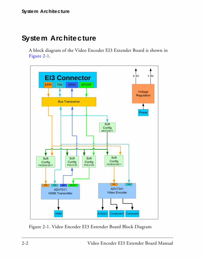
System ArchitectureA block diagram of the Video Encoder EI3 Extender Board is shown in Figure 2-1.
Figure 2-1. Video Encoder EI3 Extender Board Block Diagram
ADV7511HDMI Transmitter
HDMI Component CompositeSVIDEO
Power
Voltage Regulation
3.3V
PPI
1.8V
SoftConfig
74CB3Q16211
SoftConfig
PI3C3125
SoftConfig
PI3C3125
SoftConfig
MCP23017
TWI SPORTINT
ADV7341Video Encoder
PPI TWI
SoftConfig
74CB3Q16211
Bus Transceiver
EI3 ConnectorGPIOTWIEPPI SPORT
2-2 Video Encoder EI3 Extender Board Manual

Video Encoder EI3 Extender Board Hardware Reference
Software-Controlled Switches (SoftConfig)
On the Video Encoder EI3 Extender Board, all of the traditional mechan-ical switches/jumpers have been replaced by I2C software-controlled switches. Refer to any SoftConfig*.c file found in the installation direc-tory of CCES for an example of how to set up the SoftConfig feature of the product through software.
The SoftConfig section of this manual serves as a reference to any user that intends to modify an existing software example. If software provided by ADI is used, there should be little need to reference this section.
Care should be taken when changing SoftConfig settings not to create a conflict with interfaces. The same GPIO signal and SPICS should not be configured for more than one interface.
Overview of SoftConfigIn order to further clarify the use of electronic single FET switches and multi-channel bus switches, an example of each is illustrated and com-pared to a traditional mechanical switching solution. This is a generic example. After this generic discussion there is a detailed explanation of the SoftConfig interface specific to the extender.
Figure 2-2 shows two individual FET switches (Pericom PI3A125CEX) with reference designators UA and UB. Net names ENABLE_A and ENABLE_B control UA and UB. The default FET switch enable settings in this example are controlled by resistors RA and RB which pull the enable pin 1 of UA and UB to ground (low). In a real example, these enable signals are controlled by the Microchip IO expander. The default pull-down resistors connect the signals EXAMPLE_SIGNAL_A and EXAMPLE_SIGNAL_B and also connect sig-nals EXAMPLE_SIGNAL_C and EXAMPLE_SIGNAL_D. To disconnect EXAMPLE_SIGNAL_A from EXAMPLE_SIGNAL_B, the Microchip IO expander is
Video Encoder EI3 Extender Board Manual 2-3

Software-Controlled Switches (SoftConfig)
used to change ENABLE_A to a logic 1 through software that interfaces with the Microchip. The same procedure for ENABLE_B would disconnect EXAMPLE_SIGNAL_C from EXAMPLE_SIGNAL_D.
Figure 2-2. Example of Individual FET Switches
Figure 2-3 shows the equivalent circuit to Figure 2-2 but utilizes mechan-ical switches that are in the same package. The default is shown by black boxes located closer to the ON label of the switches. In order to disconnect these switches, physically move the switch to the OFF position.
Figure 2-3. Example of Mechanical Switch Equivalent to Figure 2-2
2-4 Video Encoder EI3 Extender Board Manual
Video Encoder EI3 Extender Board Hardware Reference
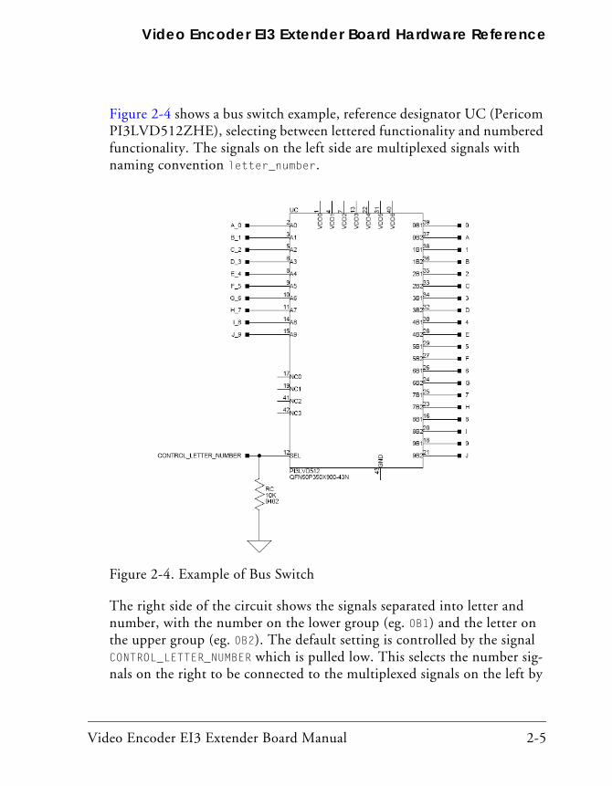
Figure 2-4 shows a bus switch example, reference designator UC (Pericom PI3LVD512ZHE), selecting between lettered functionality and numbered functionality. The signals on the left side are multiplexed signals with naming convention letter_number.
Figure 2-4. Example of Bus Switch
The right side of the circuit shows the signals separated into letter and number, with the number on the lower group (eg. 0B1) and the letter on the upper group (eg. 0B2). The default setting is controlled by the signal CONTROL_LETTER_NUMBER which is pulled low. This selects the number sig-nals on the right to be connected to the multiplexed signals on the left by
Video Encoder EI3 Extender Board Manual 2-5
Software-Controlled Switches (SoftConfig)
default. In this example, the Microchip IO expander is not shown but controls the signal CONTROL_LETTER_NUMBER and allows the user to change the selection through software.
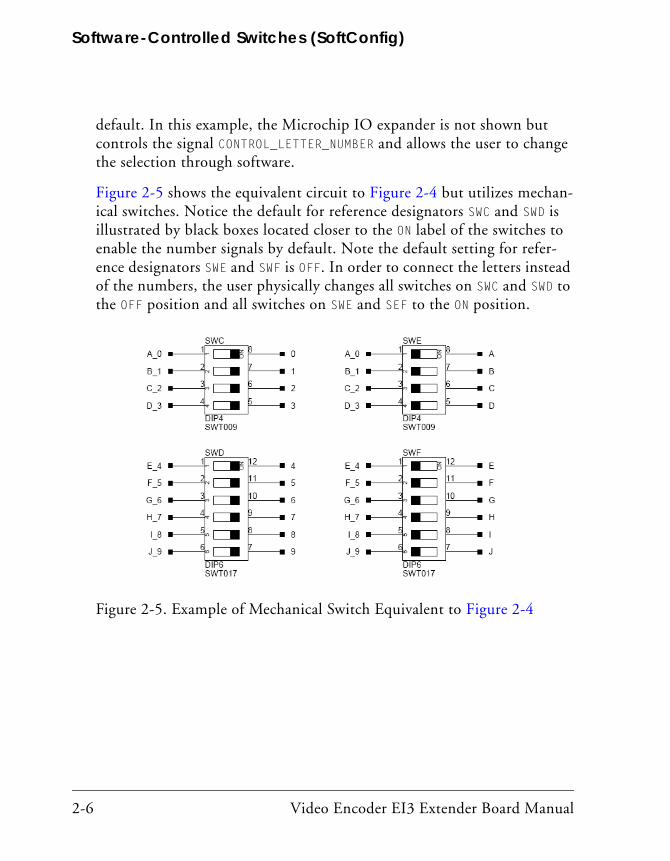
Figure 2-5 shows the equivalent circuit to Figure 2-4 but utilizes mechan-ical switches. Notice the default for reference designators SWC and SWD is illustrated by black boxes located closer to the ON label of the switches to enable the number signals by default. Note the default setting for refer-ence designators SWE and SWF is OFF. In order to connect the letters instead of the numbers, the user physically changes all switches on SWC and SWD to the OFF position and all switches on SWE and SEF to the ON position.
Figure 2-5. Example of Mechanical Switch Equivalent to Figure 2-4
2-6 Video Encoder EI3 Extender Board Manual
Video Encoder EI3 Extender Board Hardware Reference
Programming SoftConfigOn the Video Encoder EI3 Extender Board, a single Microchip MCP23017 device controls individual and electronic bus switches via TWI. The device has the following programming characteristics:
• There are two programmable GPIO registers.
GPIO Register Register Address
GPIOA 0x12
GPIOB 0x13
• Each GPIO register controls eight signals (software switches).
• By default, the GPIO signals function as input signals; therefore, all electronic switches are in the OFF state.
The signals must be programmed as output signals to override their default values. The following table shows the Microchip register addresses and values that must be written to them to program the signals as output signals.
IODIR Register IODIR Register Address Value to be Written to Program Signals as Outputs
IODIRA 0x00 0
IODIRB 0x01 0
Video Encoder EI3 Extender Board Manual 2-7

Software-Controlled Switches (SoftConfig)
Each example in Cross Core Embedded Studio includes source files that program the soft switches, even if the default settings are being used. The README for each example identifies only the signals that are being changed from their default values. The code that programs the soft switches is located in two files:
• SoftConfig_Encoder.c for configuring the extender board
• SoftConfig_xxx.c for configuring the EZ-KIT Lite/EZ-Board; xxx identifies the EZ-KIT Lite/EZ-Board file in each example.
Page 2 of Appendix B, “Video Encoder EI3 Extender Board Schematic” shows how the GPIO signals are connected to the board’s ICs.
U13 and U10-U13 are 24-bit bus switches. They are used to select how the transmitter/encoder is connected to the processor. You can select an 8-bit, 16-bit, or 24-bit interface.
U8-U9 are 2-port bus switches. They are used for selecting which GPIO signals to use as the interrupt.
U18 is an 8-port bus switch. It is used to connect/disconnect the SPORT to the ADV7511.
Table 2-1 and Table 2-2 show the output signals of the GPIO expander (U10) with a TWI address of 0100 101X, where X represents the read or write bit. The signals that control an individual FET have an entry under the FET column. The Component Connected column shows the board IC that is connected if the FET is enabled.
2-8 Video Encoder EI3 Extender Board Manual

Video Encoder EI3 Extender Board Hardware Reference
Table 2-1. Output Signals of GPIO Expander (U19 Port A)
Bit Signal Name Description FET Component Connected
Default
0 24_BIT_ADV7511 24-bit video mode U10 U14 Off
1 24_BIT_ADV7341 24-bit video mode U11 U2 Off
2 16_BIT_ADV7511 16-bit video mode U13 U14 Off
3 16_BIT_ADV7341 16-bit video mode U12 U2 Off
4 27MHZ_CLK_EN Enable 27 MHz oscillator U15 Off
5 74MHZ_CLK_EN Enable 74 MHz oscillator U14 Off
6 8_BIT_ADV7341 8-bit video mode U3 U2 Off
7 SPORT_ENABLE Enable SPORT interface U18 U14 Off
Table 2-2. Output Signals of GPIO Expander (U19 Port B)
Bit Signal Name Description FET Component Connected
Default
0 ADV7511_INT_GPIO0 Transmitter interrupt U9 U14 Off
1 ADV7511_INT_GPIO1 Transmitter interrupt U9 U14 Off
2 ADV7511_INT_GPIO2 Transmitter interrupt U19 U14 Off
3 ADV7511_INT_GPIO3 Transmitter interrupt U9 U14 Off
4 ADV7511_INT_GPIO4 Transmitter interrupt U8 U14 Off
5 ADV7511_INT_GPIO5 Transmitter interrupt U8 U14 Off
6 ADV7511_INT_GPIO6 Transmitter interrupt U8 U14 Off
7 ADV7511_INT_GPIO7 Transmitter interrupt U8 U14 Off
Video Encoder EI3 Extender Board Manual 2-9

Software-Controlled Switches (SoftConfig)
Video Encoder Mode SelectThe Video Encoder Mode Select determines whether the interface to the processors PPI is 8, 16 or 24 bits. The Video Encoder Mode select is cho-sen by driving low either the 24_BIT_ADV7511, 16_BIT_ADV7511, 24_BIT_ADV7341, 16_BIT_ADV7341 or 8_BIT_ADV7341 signal (U20 ports GPA0-GPA3, GPA6. Driving one of these signals low enables the appropriate bus switches (U10-U13 and U3).
ADV7511_INT_GPIOx SignalThe ADV7511_INT_GPIOx signal connects the interrupt signal of the ADV7511 to one of eight GPIO pins of the processor. U20 ports GPB0-GPB7 are used to select the connection to the appropriate GPIO sig-nal via the U8 and U9 bus switch.
27MHZ_CLK_EN SignalThe 27MHZ_CLK_EN signal is used to enable the onboard 27 MHz oscillator which connects to the ADV7511 and ADV7341. U20 port GPA4 is used to enable and disable the oscillator. The default is disabled.
74MHZ_CLK_EN SignalThe 74MHZ_CLK_EN signal is used to enable the onboard 74.25 MHz oscil-lator which connects to the ADV7511 and ADV7341. U20 port GPA5 is used to enable and disable the oscillator. The default is disabled.
SPORT_ENABLE SignalThe SPORT_ENABLE signal connects the audio signal of the ADV7511 to the SPORT interface of the processor. U20 port GPA7 is used to enable or dis-able the connection via the U18 bus switch. The default is disabled.
2-10 Video Encoder EI3 Extender Board Manual
Video Encoder EI3 Extender Board Hardware Reference
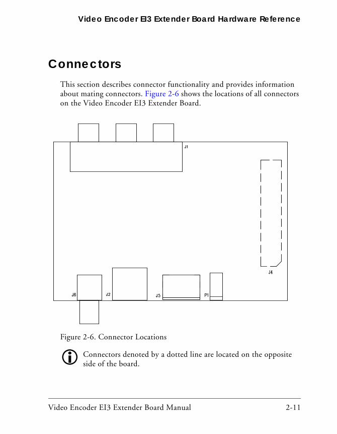
ConnectorsThis section describes connector functionality and provides information about mating connectors. Figure 2-6 shows the locations of all connectors on the Video Encoder EI3 Extender Board.
Figure 2-6. Connector Locations
Connectors denoted by a dotted line are located on the opposite side of the board.
Video Encoder EI3 Extender Board Manual 2-11

Connectors
Expansion III (EI3) Connectors (J4)One board-to-board connectors (J4) provide signals from the PPI, SPORT, TWI, and GPIO interfaces of the processor. The connector is located on the bottom side of the board.
Part Description Manufacturer Part Number
120-pin, 0.6 mm HIROSE FX8-120S-SV(21)
Mating Connector
120-pin, 0.6 mm HIROSE FX8-120P-SV1(91)
S-Video Connector (J2)The S-Video connector (J2) is a DIN connector which connects to the ADV7341. This connector can be used for Y-C mode and supports SD, ED, and HD video modes.
Part Description Manufacturer Part Number
S-Video CUI MD-40SM
Mating Cable
S-Video Cable Belkin F8V308-06
2-12 Video Encoder EI3 Extender Board Manual

Video Encoder EI3 Extender Board Hardware Reference
Component Connector (J14)The Component connector (J14) is a group of three RCA jacks which connect to the ADV7341. This connector can be used for YPrPb and RGB modes and supports SD, ED, and HD video modes.
Part Description Manufacturer Part Number
Component (3x1 RCA) CUI RCJ-32265
Mating Cable
Component Cable Belkin AV21000-06
HDMI Connector (J5)The HDMI connector (J5) is an HDMI receptacle that is connected to the ADV7511. This connector can be used for YCbCr and RGB modes and supports SD, ED, and HD video modes. It supports ARC and is v.1.4 compliant.
Part Description Manufacturer Part Number
HDMI FCI 10029449-002TLF
Mating Cable
HDMI Cable Mediabridge 91-02X-06B
Video Encoder EI3 Extender Board Manual 2-13
Connectors
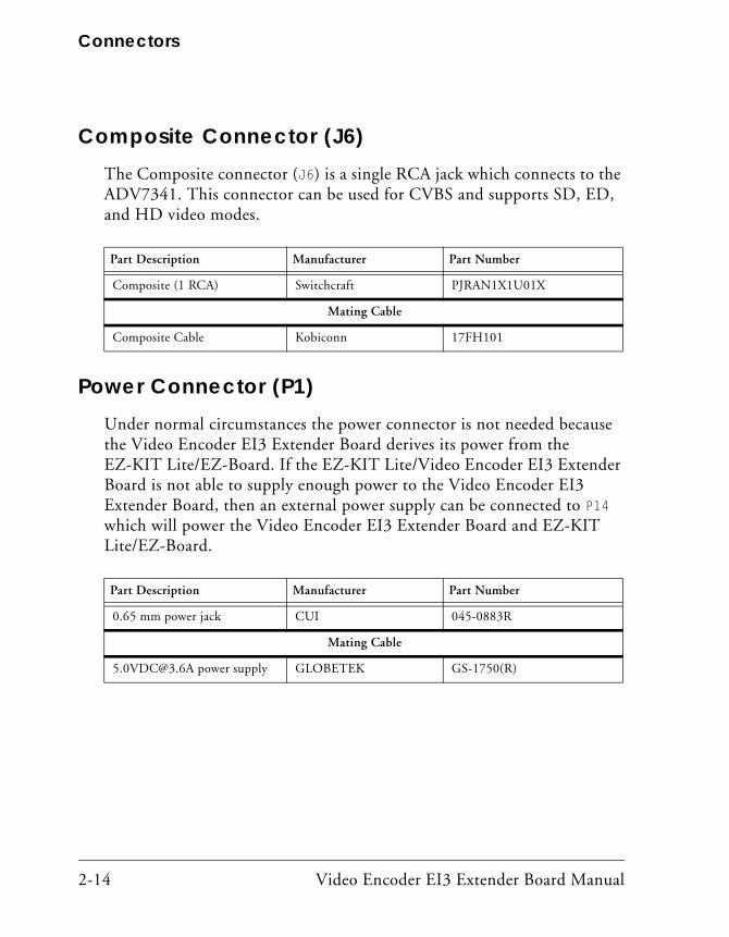
Composite Connector (J6)The Composite connector (J6) is a single RCA jack which connects to the ADV7341. This connector can be used for CVBS and supports SD, ED, and HD video modes.
Part Description Manufacturer Part Number
Composite (1 RCA) Switchcraft PJRAN1X1U01X
Mating Cable
Composite Cable Kobiconn 17FH101
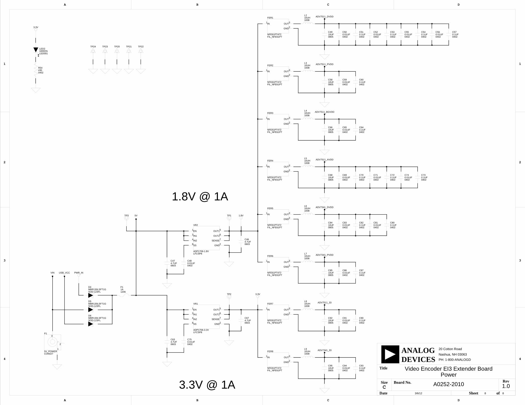
Power Connector (P1)Under normal circumstances the power connector is not needed because the Video Encoder EI3 Extender Board derives its power from the EZ-KIT Lite/EZ-Board. If the EZ-KIT Lite/Video Encoder EI3 Extender Board is not able to supply enough power to the Video Encoder EI3 Extender Board, then an external power supply can be connected to P14 which will power the Video Encoder EI3 Extender Board and EZ-KIT Lite/EZ-Board.
Part Description Manufacturer Part Number
0.65 mm power jack CUI 045-0883R
Mating Cable
[email protected] power supply GLOBETEK GS-1750(R)
2-14 Video Encoder EI3 Extender Board Manual

Video Encoder EI3 Extender Board Hardware Reference
LEDsThis section describes the on-board LEDs.
HDMI Detect LED (LED1)When LED1 is lit solid (yellow), it indicates that an HDMI device has been detected (connected to the HDMI connector (J5)).
Power LED (LED2)When LED2 is lit solid (green), it indicates that power is being supplied to the board properly.
Video Encoder EI3 Extender Board Manual 2-15

LEDs
2-16 Video Encoder EI3 Extender Board Manual

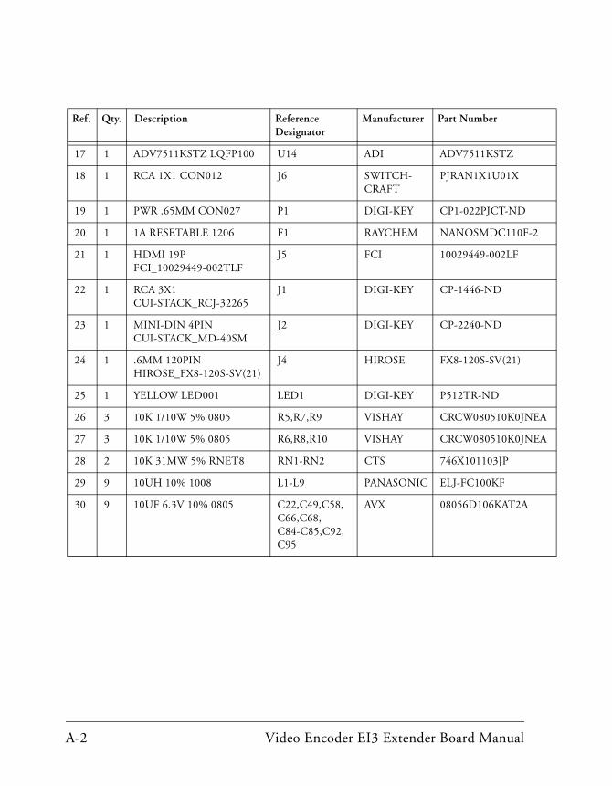
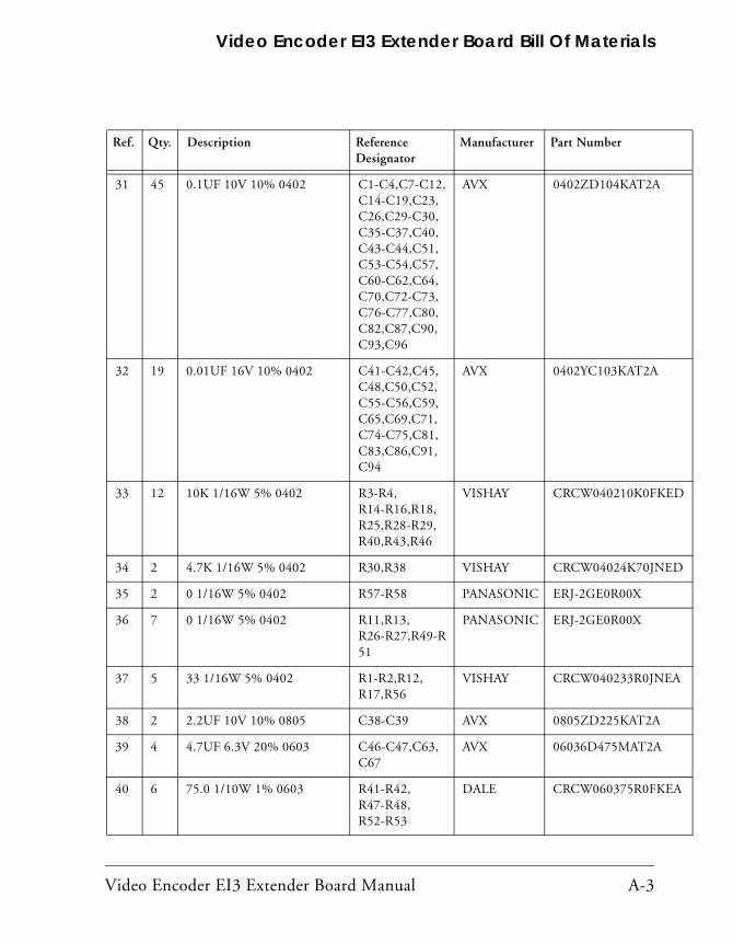
A VIDEO ENCODER EI3 EXTENDER BOARD BILL OF MATERIALS
The bill of materials corresponds to “Video Encoder EI3 Extender Board
4
7
7
Schematic” on page B-1.
Ref. Qty. Description Reference Designator
Manufacturer Part Number
1 1 SN74LVC1G125 SOT23-5 U22 TI 74LVC1G125DBVRE
2 2 SN74LVC1G04 SOT23-5 U4-U5 TI SN74LVC1G04DBVT
3 1 27MHZ OSC003 U15 EPSON SG-8002CA-MP
4 5 SN74CB3Q16211 TSSOP56 U3,U10-U13 DIGI-KEY 296-17629-1-ND
5 1 SN74AVC4T245 SOIC16 U1 DIGI-KEY 296-17930-1-ND
6 1 SN74AVC8T245 TSSOP24 U18 TI SN74AVC8T245PW
7 1 12MHZ OSC015 U17 DIGI-KEY 535-9413-2-ND
8 1 MCP23017 QFN65P600X600-29N
U19 DIGI-KEY MCP23017-E/ML-ND
9 3 PI3C3125 TSSOP14 U7-U9 PERICOM PI3C3125
10 1 74.25MHZ OSC003 U16 CTS CB3LV-3I-74M2500
11 1 74AVC24T245 LFBGA84 U6 DIGI-KEY 296-17662-1-ND
12 1 ADV7341BSTZ LQFP64 U2 ADI ADV7341BSTZ
13 3 ADA4430 SC70_6 U23-U25 ADI ADA4430-1YKSZ-R2
14 1 ADP1706-1.8V LFCSP8 VR2 ADI ADP1706ACPZ-1.8-R
15 1 ADP1706-3.3V LFCSP8 VR1 ADI ADP1706ACPZ-3.3-R
16 1 10MA AD1580BRTZ SOT23D
D7 ADI AD1580BRTZ-R2
Video Encoder EI3 Extender Board Manual A-1
A
A
17 1 ADV7511KSTZ LQFP100 U14 ADI ADV7511KSTZ
18 1 RCA 1X1 CON012 J6 SWITCH-CRAFT
PJRAN1X1U01X
19 1 PWR .65MM CON027 P1 DIGI-KEY CP1-022PJCT-ND
20 1 1A RESETABLE 1206 F1 RAYCHEM NANOSMDC110F-2
21 1 HDMI 19P FCI_10029449-002TLF
J5 FCI 10029449-002LF
22 1 RCA 3X1 CUI-STACK_RCJ-32265
J1 DIGI-KEY CP-1446-ND
23 1 MINI-DIN 4PIN CUI-STACK_MD-40SM
J2 DIGI-KEY CP-2240-ND
24 1 .6MM 120PIN HIROSE_FX8-120S-SV(21)
J4 HIROSE FX8-120S-SV(21)
25 1 YELLOW LED001 LED1 DIGI-KEY P512TR-ND
26 3 10K 1/10W 5% 0805 R5,R7,R9 VISHAY CRCW080510K0JNE
27 3 10K 1/10W 5% 0805 R6,R8,R10 VISHAY CRCW080510K0JNE
28 2 10K 31MW 5% RNET8 RN1-RN2 CTS 746X101103JP
29 9 10UH 10% 1008 L1-L9 PANASONIC ELJ-FC100KF
30 9 10UF 6.3V 10% 0805 C22,C49,C58, C66,C68, C84-C85,C92, C95
AVX 08056D106KAT2A
Ref. Qty. Description Reference Designator
Manufacturer Part Number
A-2 Video Encoder EI3 Extender Board Manual
Video Encoder EI3 Extender Board Bill Of Materials
D
D
A
A
31 45 0.1UF 10V 10% 0402 C1-C4,C7-C12,C14-C19,C23, C26,C29-C30, C35-C37,C40, C43-C44,C51, C53-C54,C57, C60-C62,C64, C70,C72-C73, C76-C77,C80, C82,C87,C90, C93,C96
AVX 0402ZD104KAT2A
32 19 0.01UF 16V 10% 0402 C41-C42,C45, C48,C50,C52, C55-C56,C59, C65,C69,C71, C74-C75,C81, C83,C86,C91, C94
AVX 0402YC103KAT2A
33 12 10K 1/16W 5% 0402 R3-R4, R14-R16,R18, R25,R28-R29, R40,R43,R46
VISHAY CRCW040210K0FKE
34 2 4.7K 1/16W 5% 0402 R30,R38 VISHAY CRCW04024K70JNE
35 2 0 1/16W 5% 0402 R57-R58 PANASONIC ERJ-2GE0R00X
36 7 0 1/16W 5% 0402 R11,R13, R26-R27,R49-R51
PANASONIC ERJ-2GE0R00X
37 5 33 1/16W 5% 0402 R1-R2,R12, R17,R56
VISHAY CRCW040233R0JNE
38 2 2.2UF 10V 10% 0805 C38-C39 AVX 0805ZD225KAT2A
39 4 4.7UF 6.3V 20% 0603 C46-C47,C63, C67
AVX 06036D475MAT2A
40 6 75.0 1/10W 1% 0603 R41-R42, R47-R48, R52-R53
DALE CRCW060375R0FKE
Ref. Qty. Description Reference Designator
Manufacturer Part Number
Video Encoder EI3 Extender Board Manual A-3

41 2 1UF 6.3V 20% 0402 C20-C21 PANASONIC ECJ-0EB0J105M
42 1 GREEN LED001 LED2 PANASONIC LN1361CTR
43 1 1.1K 1/16W 1% 0402 R37 PANASONIC ERJ-2RKF1101X
44 2 430 1/16W 1% 0402 R19,R54 DIGI-KEY 311-430LRCT-ND
45 1 VARISTOR V5.5MLA 30A 0603
R55 LITTLE-FUSE
V5.5MLA0603
46 2 0.15UF 10V 10% 0603 C31,C33 AVX 0603ZC154KAT2A
47 3 1A MBR130LSFT1G SOD-123FL
D4-D6 ON SEMI MBR130LSFT1G
48 1 27K 1/16W 5% 0402 R20 PANASONIC ERJ-2GEJ273X
49 8 4700PF XXX 2A FIL_NFE61PT
FER1-FER8 DIGI-KEY 490-2554-2-ND
50 1 887 1/10W 1% 0603 R32 DIGI-KEY 311-887HRTR-ND
51 3 5A RCLAMP0524 DIO_RCLAMP0524
D9-D11 SEMTECH RCLAMP0524P.TCT
52 1 30MA DB3X314 DIO_DB3X314
D8 PANASONIC DB3X314K0L
53 2 49.9 1/16W 1% 0402 R23-R24 STACKPOLE RMCF0402FT49R9
54 3 2.0K 1/10W 1% 0402 R21-R22,R31 PANASONIC ERJ-2RKF2001X
55 1 4.12K 1/10W 1% 0402 R33 PANASONIC ERJ-2RKF4121X
56 2 0.012UF 10V 10% 0402 C32,C34 DIGI-KEY 399-3009-2-ND
57 2 169.0 1/10W 1% 0402 R35-R36 PANASONIC ERJ-2RKF1690X
58 1 510.0 1/10W 1% 0402 R34 PANASONIC ERJ-2RKF5100X
59 3 300.0 1/10W 1% 0402 R39,R44-R45 PANASONIC ERJ-2RKF3000X
61 3 100MA BAT54S SOT23D D1-D3 FAIRCHILD BAT54S
Ref. Qty. Description Reference Designator
Manufacturer Part Number
A-4 Video Encoder EI3 Extender Board Manual

1.01 8
A0252-2010
Video Encoder EI3 Extender BoardTitle Sheet
3/6/12
D
4
3
2
1
A B C
20 Cotton Road
Nashua, NH 03063
A B C D
4
3
2
1
PH: 1-800-ANALOGD
C
Title
Size Board No.
Date Sheet of
DEVICESANALOG
Rev
Video Encoder EI3 Extender BoardSchematic

1.02 8
A0252-2010
Video Encoder EI3 Extender BoardEI3 Connector/GPIO Extender
3/6/12
D
4
3
2
1
A B C
20 Cotton Road
Nashua, NH 03063
A B C D
4
3
2
1
PH: 1-800-ANALOGD
C
Title
Size Board No.
Date Sheet of
DEVICESANALOG
Rev
J4
HIROSE_FX8-120S-SV(21)
101
100
71
70
120
118
116
114
112
110
108
106
104
102
98
96
94
92
90
88
86
84
82
80
78
76
74
72
119
117
115
113
111
109
107
105
103
99
97
95
93
91
89
87
85
83
81
79
77
75
73
69
66
6867
64
61
63
65
11
62
36
35
8
6
4
2
9
7
5
3
1
12
10
59
60
55
53
51
49
47
45
43
41
39
56
54
52
50
40
48
46
44
42
58
57
3433
16
18
20
22
14
24
26
28
30
32
13
15
17
19
21
23
25
27
29
31
37 38SPI0_SEL_CSPI0_SEL_B
SPORT1_D1
SPORT0_TDV
PPI0_FS1
RSVD5
GND6
RSVD2
PPI0_D3
GND5
PPI0_D9
PPI0_D13
SPORT0_D1
SPORT1_TDV
GND7
PPI0_FS3
RSVD4
PPI0_D11
RSVD3
PPI0_D1
PPI0_D5
PPI0_D7
SPI0_D2 SPI0_D3
RESET_OUT*
GND12
SCL1*
GPIO2
GND10
TMR_A
GND9
SPI0_RDY
GND11
RSVD8
TWI0_A0*
SPI0_SEL1/SPI0_SS*
SDA1*
GPIO0
GPIO4
GPIO6
TMR_C
RSVD6
RSVD7
RSVD9
RESET_IN*
UART0_RX
PPI0_D17
PPI0_D14
VIN
GND1
USB_VCC
PPI0_D23
PPI0_D19
RSVD1
GND2
GND3
PPI0_D21
SPORT_INT
GND8
UART0_TX
GND4
WAKE*
GND13
EXT_BOOT
SLEEP*
RSVD11 RSVD12
RSVD10
GND14
TMR_B
GND15
GPIO3
SCL0*
GND16
SPI0_MISO
SPI0_SEL_A
SPORT0_CLK
SPORT0_FS
SPORT1_D0
GND18
PPI0_FS2
RSVD15
PPI0_INT
PPI0_D4
PPI0_D6
PPI0_D10
GND21
PPI0_D16
PPI0_D20
GND22
GND23
RSVD17
TMR_D*
GPIO7*
GPIO5
GPIO1
SDA0*
SPI0_CLK
SPI0_MOSI
GND17
SPORT0_D0
SPORT1_FS
SPORT1_CLK
PPI0_CLK
RSVD14
GND19
PPI0_D2
GND20
PPI0_D8
PPI0_D12
PPI0_D15
PPI0_D18
PPI0_D22
VIO
GND24
PS_IN
RSVD13
CLKOUT
RSVD16
PPI0_D0
PWR_IN
3.3V
C4
04020.1UF
R5
DNP080510K
R610K0805
R710K0805DNP
R8
080510K
DNP
R910K0805
R10
080510K
3.3V
3.3V
U19
MCP23017QFN65P600X600-29N
17
18
19
20
5
8
9
14
16
15
11
12
28
24
23
27
22
26
21
25
1
2
3
413A2 GPB7
GPB6
GPB5
GPB4
GPB0
GPA4
GPB1
GPA5
GPB2
GPA6
GPA7
GPB3
A1
A0
INTB
INTA
RESET
SDA
SCL
VDD
GPA3
GPA2
GPA1
GPA0
R56330402
TP7
R57
DNP
00402
R58
DNP04020
TP16
R11 00402
U7
PI3C3125TSSOP14
12 11
13
9 8
10
5 6
4
2 3
1OE0
B0A0
OE1
B1A1
OE2
B2A2
OE3
B3A3
U15
27MHZOSC003
4
31
2GND
OE OUT
VDD
3.3V
U16
OSC00374.25MHZ
4
31
2GND
OE OUT
VDD
3.3V
R1330402
R2
040233
R3
040210K
3.3V
C290.1UF0402
R410K0402
3.3V
C2
04020.1UF
3.3V
C30.1UF0402
U4
SN74LVC1G04SOT23-5
U5
SOT23-5SN74LVC1G04
R2510K0402
3.3V
3.3V
C30
04020.1UF
C960.1UF0402
EI3_GPIO0 EI3_GPIO1
EI3_GPIO2 EI3_GPIO3
EI3_GPIO4 EI3_GPIO5
EI3_GPIO6 EI3_GPIO7
EI3_SCL
EI3_SCL
EI3_SDA
EI3_SDA
EI3_SPORT1_CLK
EI3_SPORT1_CLK
EI3_SPORT1_FS
EI3_SPORT1_FS
EI3_SPORT1_D0
EI3_SPORT0_FS
EI3_SPORT0_FSEI3_SPORT0_CLK
EI3_SPORT0_CLK
EI3_SPORT0_D1 EI3_SPORT1_D1
24_BIT_ADV7511
EI3_PPID18
EI3_PPID17EI3_PPID16
EI3_PPID23
EI3_PPID21
EI3_PPID22
EI3_PPID19
EI3_PPID2016_BIT_ADV7341
EI3_PPIFS1
EI3_PPIFS2
16_BIT_ADV7511
24_BIT_ADV7341
VIN
USB_VCC
ADV7511_INT_GPIO7
ADV7511_INT_GPIO6
ADV7511_INT_GPIO5
ADV7511_INT_GPIO4
ADV7511_INT_GPIO3
ADV7511_INT_GPIO2
ADV7511_INT_GPIO1
ADV7511_INT_GPIO0
EI3_PPID0
EI3_PPID2
EI3_PPID4
EI3_PPID6
EI3_PPID8
EI3_PPID10
EI3_PPID12
EI3_PPID14
EI3_PPID1
EI3_PPID3
EI3_PPID5
EI3_PPID7
EI3_PPID9
EI3_PPID11
EI3_PPID13
EI3_PPID15
SPORT_ENABLE
EI3_SPORT0_D0
EI3_PPIFS3
27MHZ_CLK_EN
27MHZ_CLK_EN
74MHZ_CLK_EN
74MHZ_CLK_EN
EI3_PPICLK
EI3_RESET
EI3_RESET
8_BIT_ADV7341
PPICLK
x is the R/W bit. Read - 1, Write - 0
SoftConfig control signals
TWI Address 0100 101x
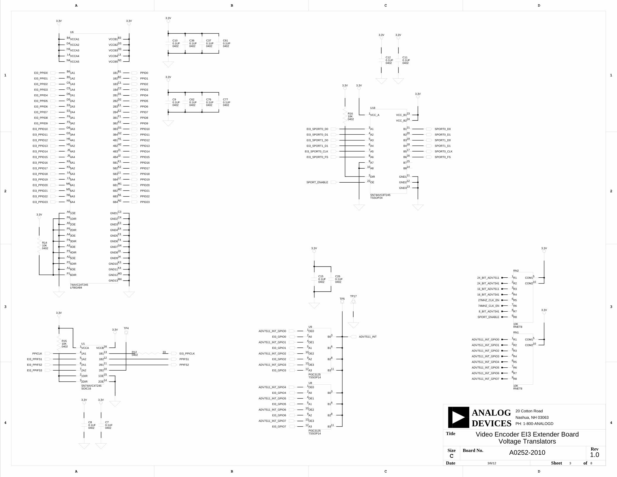
A0252-2010
Video Encoder EI3 Extender BoardVoltage Translators
3/6/12
1.03 8
D
4
3
2
1
A B C
20 Cotton Road
Nashua, NH 03063
A B C D
4
3
2
1
PH: 1-800-ANALOGD
C
Title
Size Board No.
Date Sheet of
DEVICESANALOG
Rev
TP4
U8
TSSOP14PI3C3125
12 11
13
9 8
10
5 6
4
2 3
1OE0
B0A0
OE1
B1A1
OE2
B2A2
OE3
B3A3
U9
TSSOP14PI3C3125
12 11
13
9 8
10
5 6
4
2 3
1OE0
B0A0
OE1
B1A1
OE2
B2A2
OE3
B3A3
RN1
10KRNET8
10
5
9
8
7
6
4
3
2
1R1
R2
R3
R4
R5
R6
R7
R8
COM1
COM2
C150.1UF0402
3.3V
3.3V3.3V
3.3V
3.3V
3.3V
C260.1UF0402
U1
SN74AVC4T245SOIC16
15
10
11
12
13
161
4
6
2
7
3
5
142OE
1A2
2DIR
2A2
1DIR
2A1
1A1
VCCA VCCB
1B1
1B2
2B1
2B2
1OE
U18
SN74AVC8T245TSSOP24
22
24
231
13
12
112
14
15
16
17
18
19
20
21
10
9
8
7
6
5
4
3A1
A2
A3
A4
A5
A6
A7
A8
B1
B2
B3
B4
B5
B6
B7
B8
DIR GND1
GND2
GND3
VCC_A VCC_B1
VCC_B2
OE
3.3V
74AVC24T245LFBGA84
U6
M4
M3
K4
K3
J4
J3
G4
F4
F3
A6
P6
A1
P1
A2
P2
A3
P3
A4
P4
N3N4
L3
H3
D3
B3
L4
H4
D4
B4
E4
E3
C4
C3
A5
H5
J6
J5
K6
K5
L6
L5
M6
N6
N5
H6
M5
F1
M1
F2
M2
G1
N1
G2
N2
P5
B6
B5
C6
C5
D6
D5
E6
E5
C2
J2
J1
C1
H2
B2
H1
B1
D1
K1
D2
K2
E1
L1
L2
E2
G5
G6
F5
F63A1
3A2
3A3
3A4
2B4
5B4
5B3
2B3
5B2
2B2
5B1
2B1
1B1
4B1
1B2
4B2
1B3
4B3
4B4
1B4
2A4
2A3
2A2
2A1
1A4
1A3
1A2
1A1
2DIR
6B4
3B4
6B3
3B3
6B2
3B2
6B1
3B1
6A2
4A1
6A4
6A3
6A1
5A4
5A3
5A2
5A1
4A4
4A3
4A2
2OE
GND1
GND2
GND3
GND4
VCCA1
VCCA2
VCCA3
VCCA4
VCCB1
VCCB2
VCCB3
VCCB4
VCCA5 VCCB5
3DIR
3OE
4DIR
4OE
5DIR
5OE
6DIR
6OE
1DIR
1OE
GND5
GND6
GND7
GND8
GND9
GND10
GND11
GND12
GND13
TP17TP5
R14
040210K
3.3V
040210KR15
R12 330402
3.3V
3.3V
3.3V
3.3V
R16
040210K
3.3V
RN2
10KRNET8
10
5
9
8
7
6
4
3
2
1R1
R2
R3
R4
R5
R6
R7
R8
COM1
COM2
3.3V
3.3V
C70.1UF0402
C8
04020.1UF
3.3V
C90.1UF0402
C10
04020.1UF
3.3V
C110.1UF0402
C12
04020.1UF
C36
04020.1UF
C370.1UF0402
C61
04020.1UF
C620.1UF0402
C76
04020.1UF
C770.1UF0402
EI3_GPIO0
EI3_GPIO1
EI3_GPIO2
EI3_GPIO3
EI3_GPIO4
EI3_GPIO5
EI3_GPIO6
EI3_GPIO7
EI3_SPORT1_D0
EI3_SPORT0_FS
EI3_SPORT0_CLK
EI3_SPORT0_D1
EI3_SPORT1_D1
24_BIT_ADV7511
EI3_PPID18
EI3_PPID17
EI3_PPID16
EI3_PPID23
EI3_PPID21
EI3_PPID22
EI3_PPID19
EI3_PPID20
16_BIT_ADV7341
EI3_PPIFS1
EI3_PPIFS2
16_BIT_ADV7511
24_BIT_ADV7341
ADV7511_INT_GPIO7
ADV7511_INT_GPIO7
ADV7511_INT_GPIO6
ADV7511_INT_GPIO6
ADV7511_INT_GPIO5
ADV7511_INT_GPIO5
ADV7511_INT_GPIO4
ADV7511_INT_GPIO4
ADV7511_INT_GPIO3
ADV7511_INT_GPIO3
ADV7511_INT_GPIO2ADV7511_INT_GPIO2
ADV7511_INT_GPIO1ADV7511_INT_GPIO1
ADV7511_INT_GPIO0
ADV7511_INT_GPIO0
ADV7511_INT
EI3_PPID0
EI3_PPID2
EI3_PPID4
EI3_PPID6
EI3_PPID8
EI3_PPID10
EI3_PPID12
EI3_PPID14
EI3_PPID1
EI3_PPID3
EI3_PPID5
EI3_PPID7
EI3_PPID9
EI3_PPID11
EI3_PPID13
EI3_PPID15
SPORT0_D0
PPID0
PPID1
PPID2
PPID3
PPID4
PPID5
PPID6
PPID7
PPID8
PPID9
PPID10
PPID11
PPID12
PPID13
PPID14
PPID15
PPID16
PPID17
PPID18
PPID19
PPID20
PPID21
PPID22
PPID23
PPIFS1
PPIFS2
SPORT_ENABLE
SPORT_ENABLE
EI3_SPORT0_D0
SPORT0_D1
SPORT1_D0
SPORT1_D1
SPORT0_CLK
SPORT0_FS
EI3_PPIFS3
27MHZ_CLK_EN
74MHZ_CLK_EN
EI3_PPICLK
8_BIT_ADV7341
PPICLK

A0252-2010
Video Encoder EI3 Extender BoardVideo Modes
3/6/12
1.04 8
D
4
3
2
1
A B C
20 Cotton Road
Nashua, NH 03063
A B C D
4
3
2
1
PH: 1-800-ANALOGD
C
Title
Size Board No.
Date Sheet of
DEVICESANALOG
Rev
3.3V3.3V
3.3V
C160.1UF0402
U10
TSSOP56SN74CB3Q16211
178 19
55
56
3
29
31
39
40
41
54
42
43
44
50
53
12
37
36
35
34
45
33
32
30
46
47
48
51
52
2
14
13
11
10
9
7
6
5
4
16
18
20
21
22
23
24
25
27
28
15
26
38 49G
ND
4
GN
D3
2A10
2A1
2A12
2A11
2A9
2A8
2A7
2A6
2A5
2A4
2A3
2A2
1A3
1A4
1A5
1A6
1A7
1A8
1A9
1A11
1A12
1A1
1B3
1B4
1B6
1B7
1B8
2B11
2B9
2B8
1B9
2B7
2B6
2B5
2B4
1A10
1B2
1B5
1B10
1B11
1B12
1B1
2B1
2B2
2B3
2B10
2B12
1A2
1OE
2OE
GN
D2
GN
D1
VC
C U11
TSSOP56SN74CB3Q16211
178 19
55
56
3
29
31
39
40
41
54
42
43
44
50
53
12
37
36
35
34
45
33
32
30
46
47
48
51
52
2
14
13
11
10
9
7
6
5
4
16
18
20
21
22
23
24
25
27
28
15
26
38 49G
ND
4
GN
D3
2A10
2A1
2A12
2A11
2A9
2A8
2A7
2A6
2A5
2A4
2A3
2A2
1A3
1A4
1A5
1A6
1A7
1A8
1A9
1A11
1A12
1A1
1B3
1B4
1B6
1B7
1B8
2B11
2B9
2B8
1B9
2B7
2B6
2B5
2B4
1A10
1B2
1B5
1B10
1B11
1B12
1B1
2B1
2B2
2B3
2B10
2B12
1A2
1OE
2OE
GN
D2
GN
D1
VC
C
U12
SN74CB3Q16211TSSOP56
178 19
55
56
3
29
31
39
40
41
54
42
43
44
50
53
12
37
36
35
34
45
33
32
30
46
47
48
51
52
2
14
13
11
10
9
7
6
5
4
16
18
20
21
22
23
24
25
27
28
15
26
38 49G
ND
4
GN
D3
2A10
2A1
2A12
2A11
2A9
2A8
2A7
2A6
2A5
2A4
2A3
2A2
1A3
1A4
1A5
1A6
1A7
1A8
1A9
1A11
1A12
1A1
1B3
1B4
1B6
1B7
1B8
2B11
2B9
2B8
1B9
2B7
2B6
2B5
2B4
1A10
1B2
1B5
1B10
1B11
1B12
1B1
2B1
2B2
2B3
2B10
2B12
1A2
1OE
2OE
GN
D2
GN
D1
VC
C
C140.1UF0402
3.3V
3.3V
3.3V
C18
04020.1UF
U13
SN74CB3Q16211TSSOP56
178 19
55
56
3
29
31
39
40
41
54
42
43
44
50
53
12
37
36
35
34
45
33
32
30
46
47
48
51
52
2
14
13
11
10
9
7
6
5
4
16
18
20
21
22
23
24
25
27
28
15
26
38 49G
ND
4
GN
D3
2A10
2A1
2A12
2A11
2A9
2A8
2A7
2A6
2A5
2A4
2A3
2A2
1A3
1A4
1A5
1A6
1A7
1A8
1A9
1A11
1A12
1A1
1B3
1B4
1B6
1B7
1B8
2B11
2B9
2B8
1B9
2B7
2B6
2B5
2B4
1A10
1B2
1B5
1B10
1B11
1B12
1B1
2B1
2B2
2B3
2B10
2B12
1A2
1OE
2OE
GN
D2
GN
D1
VC
C
3.3V
3.3V
C17
04020.1UF
TP9
TP6
TP8
R29
040210K
3.3VC1
04020.1UF
3.3V
TP10
3.3V
U3
SN74CB3Q16211TSSOP56
178 19
55
56
3
29
31
39
40
41
54
42
43
44
50
53
12
37
36
35
34
45
33
32
30
46
47
48
51
52
2
14
13
11
10
9
7
6
5
4
16
18
20
21
22
23
24
25
27
28
15
26
38 49G
ND
4
GN
D3
2A10
2A1
2A12
2A11
2A9
2A8
2A7
2A6
2A5
2A4
2A3
2A2
1A3
1A4
1A5
1A6
1A7
1A8
1A9
1A11
1A12
1A1
1B3
1B4
1B6
1B7
1B8
2B11
2B9
2B8
1B9
2B7
2B6
2B5
2B4
1A10
1B2
1B5
1B10
1B11
1B12
1B1
2B1
2B2
2B3
2B10
2B12
1A2
1OE
2OE
GN
D2
GN
D1
VC
C
TP11
ADV7511_D4
ADV7511_D20
ADV7511_D20
ADV7511_D21
ADV7511_D21
ADV7511_D22
ADV7511_D22
ADV7511_D23
ADV7511_D23
ADV7511_D28
ADV7511_D28
ADV7511_D29
ADV7511_D29
ADV7511_D30
ADV7511_D30
ADV7511_D31
ADV7511_D31
ADV7511_D32
ADV7511_D32
ADV7511_D33
ADV7511_D33
ADV7511_D34
ADV7511_D34
ADV7511_D35
ADV7511_D35
24_BIT_ADV7511
16_BIT_ADV7341
ADV7341_Y2
ADV7341_Y2
ADV7341_Y3
ADV7341_Y3
ADV7341_Y4
ADV7341_Y4
ADV7341_Y5
ADV7341_Y5
ADV7341_Y6
ADV7341_Y6
ADV7341_Y7
ADV7341_Y7
ADV7341_Y8
ADV7341_Y8
ADV7341_Y9
ADV7341_Y9ADV7341_S2
ADV7341_S2ADV7341_S3
ADV7341_S3ADV7341_S4
ADV7341_S4ADV7341_S5
ADV7341_S5ADV7341_S6
ADV7341_S6ADV7341_S7
ADV7341_S7ADV7341_S8
ADV7341_S8ADV7341_S9
ADV7341_S9
ADV7341_C2
ADV7341_C2
ADV7341_C3
ADV7341_C3
ADV7341_C4
ADV7341_C4
ADV7341_C5
ADV7341_C5
ADV7341_C6
ADV7341_C6
ADV7341_C7
ADV7341_C7
ADV7341_C8
ADV7341_C8
ADV7341_C9
ADV7341_C9
ADV7511_D5
ADV7511_D6
ADV7511_D7
ADV7511_D8
ADV7511_D9
ADV7511_D10
ADV7511_D11
ADV7511_D16
ADV7511_D17
ADV7511_D18
ADV7511_D19
16_BIT_ADV7511
24_BIT_ADV7341
PPID0
PPID0PPID0
PPID0PPID0
PPID1
PPID1PPID1
PPID1PPID1
PPID2
PPID2PPID2
PPID2PPID2
PPID3
PPID3PPID3
PPID3PPID3
PPID4
PPID4PPID4
PPID4PPID4
PPID5
PPID5PPID5
PPID5PPID5
PPID6
PPID6PPID6
PPID6PPID6
PPID7
PPID7PPID7
PPID7PPID7
PPID8PPID8
PPID8PPID8
PPID9PPID9
PPID9PPID9
PPID10PPID10
PPID10PPID10
PPID11PPID11
PPID11PPID11
PPID12PPID12
PPID12PPID12
PPID13PPID13
PPID13PPID13
PPID14PPID14
PPID14PPID14
PPID15PPID15
PPID15PPID15
PPID16PPID16
PPID17PPID17
PPID18PPID18
PPID19PPID19
PPID20PPID20
PPID21PPID21
PPID22PPID22
PPID23PPID23
ADV7511_D24
ADV7511_D25
ADV7511_D26
ADV7511_D27
8_BIT_ADV734124-Bit ModeRGB 4:4:4
24-Bit ModeRGB 4:4:4
YCbCr 4:2:216-Bit Mode
YCbCr 4:2:216-Bit Mode
YCbCr 4:2:28-Bit Mode

A0252-2010
Video Encoder EI3 Extender BoardADV7511
3/6/12
1.05 8
D
4
3
2
1
A B C
20 Cotton Road
Nashua, NH 03063
A B C D
4
3
2
1
PH: 1-800-ANALOGD
C
Title
Size Board No.
Date Sheet of
DEVICESANALOG
Rev
ADV7511KSTZLQFP100
U14
28
47413429252421
1009975443727232220
30
54
53
52
38
56
55
46
17
16
11
15
14
13
12
10
3
4
5
6
7
8
9
57
58
61
60
59
62
51
50
48
42
2677764919
45
79
97
63
64
73
74
87
88
43
1
39
40
3118
35
36
67
66
65
86
32
33
68
70
71
72
78
80
81
82
83
84
98
2
69
89
96
95
94
93
92
91
90
85D11
D6
D5
D4
D3
D2
D1
D0
D7
D23
VSYNC
HSYNC
D12
D13
D14
D15
D16
D17
D20
D21
D22
D24
TXC+
TXC-
D10
D27
D26
D25
TX0+
TX0-
GN
D1
GN
D6
TX1+
TX1-
DV
DD
1
TX2+
D8
D9
D18
D19
D28
D29
DE
CLK
INT
DV
DD
2D
VD
D3
DV
DD
4D
VD
D5
BG
VD
D
TX2-
CEC
CEC_CLK
HEAC-
D30
D33
D32
D31
D34
D35
DSD_CLK/DST_CLK
DSD5/DST_FL
DSD4/DST_ST
DSD3
DSD2
DSD1
DSD0
SPDIF
I2S0
I2S1
I2S2
I2S3
MCLK
SCLK
LRCLK
SPDIF_OUT
SCL
SDA
PD
HEAC+
DDCSCL
DDCSDA
HPD
GN
D2
GN
D3
GN
D4
GN
D5
GN
D7
GN
D8
GN
D9
GN
D10
GN
D11
PV
DD
1P
VD
D2
PV
DD
3
AV
DD
1A
VD
D2
AV
DD
3
DV
DD
_33V
R_E
XT
R328870603
R2349.90402
DIO_DB3X314
DB3X314D8
R2027K0402
R212.0K0402
R22
04022.0K
R24
040249.9
C201UF0402
C21
04021UF
R2700402
R2810K0402
R304.7K0402
R312.0K0402
TP19
R13 00402
L1
100810UH
C2210UF0805
U17
12MHZOSC015
4
31
2GND
OE OUT
VDD
R17330402
R1810K0402
C19
04020.1UF
TP12
U22
SN74LVC1G125SOT23-5
1
LED1YELLOWLED001
R194300402
3.3V
TP13 TP14
C23
04020.1UF
TP25
EI3_SCL
EI3_SDA
TXC+
TX0-
TX0+
TX1-
TX1+
TX2-
TX2+
CEC
CEC_CLK
CEC_CLK
TXC-
DDCSCL
DDCSDA
HEAC-/HPD
HEAC-/HPD
HEAC-/HPD
HEAC+
ADV7511_D4
ADV7511_D20
ADV7511_D21
ADV7511_D22
ADV7511_D23
ADV7511_D28
ADV7511_D29
ADV7511_D30
ADV7511_D31
ADV7511_D32
ADV7511_D33
ADV7511_D34
ADV7511_D35
ADV7511_D5
ADV7511_D6
ADV7511_D7
ADV7511_D8
ADV7511_D9
ADV7511_D10
ADV7511_D11
ADV7511_D16
ADV7511_D17
ADV7511_D18
ADV7511_D19
ADV7511_PVDD
ADV7511_PVDD
ADV7511_BGVDD
ADV7511_AVDD ADV7511_AVDD
ADV7511_AVDD
ADV7511_DVDD
ADV7511_DVDD
ADV7511_33
ADV7511_33
ADV7511_33
ADV7511_INT
SPORT0_D0
PPIFS1
PPIFS2
ADV7511_PLVDD
ADV7511_PLVDD
SPORT0_D1
SPORT1_D0
SPORT1_D1
SPORT0_CLK
SPORT0_FS
ADV7511_D24
ADV7511_D25
ADV7511_D26
ADV7511_D27
PPICLK
5V
HDMI Device Detected
Close to U14 as possible and opposite pcb side
TWI Address 0111 001xx is the R/W bit. Read - 1, Write - 0

R33
04024.12K
R34
0402510.0
R35169.00402
C31
06030.15UF
C320.012UF0402
A0252-2010
Video Encoder EI3 Extender BoardADV7341
3/6/12
1.06 8
D
4
3
2
1
A B C
20 Cotton Road
Nashua, NH 03063
A B C D
4
3
2
1
PH: 1-800-ANALOGD
C
Title
Size Board No.
Date Sheet of
DEVICESANALOG
Rev
ADV7341BSTZLQFP64
U2
19
48
36
47
46
31
35454134156
49
50
24
23
63
29
28
62
61
13
12
30
33
10
37
38
4032645711
20
21
39
42
25
26
27
51
43
44
18
16
15
14
60
59
58
55
54
53
22
17
9
2
3
4
5
6
7
8
52S1
Y6
Y5
Y4
Y3
Y2
Y1
Y0
Y7
C3
P_HSYNC
S2
S3
S4
S5
S6
S7
C0
C1
C2
C4
DAC1
DAC2
S0
C7
C6
C5
DAC3
DAC4
SCL
SDA
DG
ND
1
DG
ND
2
GN
D_I
O
PG
ND
AG
ND
DAC5
DAC6
VD
D1
EXT_LF1
CLKIN_A
Y8
Y9
S8
S9
C8
C9
CLKIN_B
P_VSYNC
P_BLANK
S_HSYNC
S_VSYNC
VD
D2
VD
D_I
O
PV
DD
VA
A
CO
MP
1
CO
MP
2
EXT_LF2
VREF
RSET1
RSET2
SFL
ALSB
R53
060375.0
C330.15UF0603
C34
04020.012UF
R36169.00402
R5275.00603
R48
060375.0
C350.1UF0402
SOT23D
AD1580BRTZD7
R371.1K0402
R384.7K0402
C382.2UF0805
C39
08052.2UF
R26 00402
3.3V
TP15
EI3_SCL
EI3_SDA
DAC2
DAC2
DAC6
DAC5
DAC4
DAC1
DAC1
DAC3
DAC3
ADV7341_Y2
ADV7341_Y3
ADV7341_Y4
ADV7341_Y5
ADV7341_Y6
ADV7341_Y7
ADV7341_Y8
ADV7341_Y9
ADV7341_S2
ADV7341_S3
ADV7341_S4
ADV7341_S5
ADV7341_S6
ADV7341_S7
ADV7341_S8
ADV7341_S9
ADV7341_C2
ADV7341_C3
ADV7341_C4
ADV7341_C5
ADV7341_C6
ADV7341_C7
ADV7341_C8
ADV7341_C9
ADV7341_PVDD
ADV7341_PVDD
ADV7341_DVDD
ADV7341_33
ADV7341_33
ADV7341_33
PPIFS1
PPIFS2
PPICLK
Place close to U2
Place as close to U2 as possibleand on same pcb side
TWI Address 0101 011xx is the R/W bit. Read - 1, Write - 0

A0252-2010 1.07 8
Video Encoder EI3 Extender BoardVideo Connectors
3/6/12
D
4
3
2
1
A B C
20 Cotton Road
Nashua, NH 03063
A B C D
4
3
2
1
PH: 1-800-ANALOGD
C
Title
Size Board No.
Date Sheet of
DEVICESANALOG
Rev
CUI-STACK_RCJ-32265RCA
J1
5
6
3
4
1
2 R
G
B
ADA4430SC70_6
U23
43
52
61VIN VS+
GND PD
SAG VOUTR39300.00402
R4010K0402
R42
060375.0
R43
040210K
R44
0402300.0 ADA4430
SC70_6
U24
43
52
61VIN VS+
GND PD
SAG VOUT
ADA4430SC70_6
U25
43
52
61VIN VS+
GND PD
SAG VOUTR45300.00402
R4610K0402
R4775.00603
C400.1UF0402
C410.01UF0402
HDMIFCI_10029449-002TLF
J5
19
18
17
16
15
14
13
12
11
10
9
8
6
7
5
1
2
3
4 TMDS_DATA1+
TMDS_DATA2-
TMDS_SHIELD2
TMDS_DATA2+
TMDS_SHIELD1
TMDS_DATA0+
TMDS_DATA1-
TMDS_SHIELD0
TMDS_DATA0-
TMDS_CLOCK+
TMDS_CLK_SHIELD
TMDS_CLOCK-
CEC
HEC
SCL
SDA
DDC/CEC_GND
+5V
HOT_PLUG_DETECT
C420.01UF0402
C430.1UF0402
C44
04020.1UF
C45
04020.01UF
BAT54S
SOT23D
D1
1 2
3
BAT54S
SOT23D
D2
1 2
3
BAT54S
SOT23D
D3
1 2
3
3.3V
RCLAMP0524DIO_RCLAMP0524
D10
3
6
7
92
1
5
8
10
4IN3
OUT1
GND2
IN4
IN1
IN2 OUT2
OUT3
OUT4
GND1
RCLAMP0524DIO_RCLAMP0524
D11
3
6
7
92
1
5
8
10
4IN3
OUT1
GND2
IN4
IN1
IN2 OUT2
OUT3
OUT4
GND1
CUI-STACK_MD-40SMMINI-DIN
J2
765
4
231GND1
Y GND2
CGND3GND4GND5
DNP
EDAC_634-015-263-032DSUB
J3
17
16
11
10
12
15
9
14
13
2
8
7
63
51
4GND1RED
GND2
BLUEGND3
GND4
GND5
GREEN
HS
VS
VGA_5V
VGA_SCL
VGA_SDA
GND6
GND7
GND8
GND9
R49
04020
R5000402
R51
04020
RCLAMP0524DIO_RCLAMP0524
D9
3
6
7
92
1
5
8
10
4IN3
OUT1
GND2
IN4
IN1
IN2 OUT2
OUT3
OUT4
GND1
R55VARISTOR
0603
R4175.00603
J6RCA
CON012
2
1
DAC2
DAC6
DAC5
DAC4
TXC+
TXC+
TX0-
TX0-
TX0+
TX0+
TX1-
TX1-
TX1+
TX1+
TX2-
TX2-
TX2+
TX2+
CEC
CEC
TXC-
TXC-
DDCSCL
DDCSCL
DDCSDA
DDCSDA
HEAC-/HPD
HEAC-/HPD
HEAC+
HEAC+
DAC1
DAC3
ADV7341_33
ADV7341_33
ADV7341_33
ADV7341_33
ADV7341_33
ADV7341_33
PPIFS1
PPIFS2
5V
75 Ohm traces
75 Ohm traces
Component
Composite
S-Video
HDMI
VGA
Terminators close to video filters
Terminator close to video filter
Place close to ADV7341
Place close to ADV7341
Place close to ADV7341
100 Ohm diff pairs(50 Ohms to GND)
R49-R51 should be very close to J3.
1.08 8
A0252-2010
Video Encoder EI3 Extender BoardPower
3/6/12
D
4
3
2
1
A B C
20 Cotton Road
Nashua, NH 03063
A B C D
4
3
2
1
PH: 1-800-ANALOGD
C
Title
Size Board No.
Date Sheet of
DEVICESANALOG
Rev
VR2
LFCSP8ADP1706-1.8V
8
7
6
5
4
3
2
1EN
GND
IN1
IN2
OUT1
OUT2
SENSE
SS
C634.7UF0603
C67
06034.7UF
C750.01UF0402
C46
06034.7UF
C474.7UF0603
C480.01UF0402
VR1
ADP1706-3.3VLFCSP8
8
7
6
5
4
3
2
1EN
GND
IN1
IN2
OUT1
OUT2
SENSE
SS
FIL_NFE61PT
FER1
2
31IN OUT
GND
NFE61PT472
L210UH1008
C4910UF0805
C500.01UF0402
C510.1UF0402
C52
04020.01UF
C53
04020.1UF
C540.1UF0402
TP20
1.8V
LED2GREENLED001
D5MBR130LSFT1GSOD-123FL
TP1
C550.01UF0402
C56
04020.01UF
C57
04020.1UF
L3
100810UH
FIL_NFE61PT
FER2
2
31IN OUT
GND
NFE61PT472C58
080510UF
C59
04020.01UF
C60
04020.1UF
TP2
L8
100810UH
FIL_NFE61PT
FER7
2
31IN OUT
GND
NFE61PT472C90
04020.1UF
C91
04020.01UF
C92
080510UF
C640.1UF0402
C650.01UF0402
C6610UF0805FIL_NFE61PT
FER3
2
31IN OUT
GND
NFE61PT472
L410UH1008
L5
100810UH
FIL_NFE61PT
FER4
2
31IN OUT
GND
NFE61PT472C68
080510UF
C69
04020.01UF
C70
04020.1UF
C710.01UF0402
C720.1UF0402
C73
04020.1UF
C74
04020.01UF
L910UH1008
FIL_NFE61PT
FER8
2
31IN OUT
GND
NFE61PT472
C80
04020.1UF
C81
04020.01UF
C820.1UF0402
C830.01UF0402
C8410UF0805FIL_NFE61PT
FER5
2
31IN OUT
GND
NFE61PT472
L610UH1008
L7
100810UH
FIL_NFE61PT
FER6
2
31IN OUT
GND
NFE61PT472C85
080510UF
C86
04020.01UF
C87
04020.1UF
C930.1UF0402
C940.01UF0402
C9510UF0805
PWR_IN
D4MBR130LSFT1GSOD-123FL
5V_POWER
P1
CON027
1
2
3
3.3V
R54
0402430
3.3V
F11A1206
TP3
TP21 TP22TP23TP24
D6
SOD-123FLMBR130LSFT1G
ADV7341_PVDD
ADV7511_PVDD
ADV7511_BGVDD
ADV7511_AVDD
ADV7341_DVDD
ADV7511_DVDD
ADV7511_33
ADV7341_33
VIN USB_VCC
5V
1.8V @ 1A
3.3V @ 1A
I INDEX
Numerics composite (J6), 2-14
27MHZ_CLK_EN signal, 2-1074MHZ_CLK_EN signal, 2-10
AADV7341 video encoder, ixADV7511_INT_GPIOx signal, 2-10ADV7511 video encoder, ixarchitecture, of Video Encoder EI3 Extender
Board, 2-2
Bbill of materials, A-1block diagram of Video Encoder EI3 Extender
Board, 2-2board design database, 1-7board schematic (Video Encoder EI3 Extender
Board), B-1bus switch, 2-5
example, 2-5
Ccomponent connector (J14), 2-13composite connector (J6), 2-14configuration, of Video Encoder EI3 Extender
Board, 1-2connector locations, 2-11connectors
120-pin 0.6 mm pitch, 2-12component (J14), 2-13
expansion III (EI3) (J4), 2-12HDMI (J5), 2-13power (P1), 2-14single RCA jack, 2-14S-video DIN (J2), 2-12triple RCA jack (J4), 2-13
contents, of this extender board package, 1-2
Ddesign reference info, 1-7
EEngineerZone, xivexpansion III (EI3) connectors (J4), 2-12extender board block diagram, 2-2
FFET switches, 2-3
example, 2-4
HHDMI connector (J5), 2-13HDMI Detect LED (LED1), 2-15
Iinstallation, of Video Encoder EI3 Extender
Board, 1-2interfaces, x
Video Encoder EI3 Extender Board Manual I-1
Index
LLEDs, 2-15
HDMI Detect (LED1), 2-15power (LED2), 2-15
Mmechanical switch, 2-4, 2-6
Nnotation conventions, xv
Ppackage contents, 1-2power connector (P1), 2-14power LED (LED2), 2-15product information, xiiiproduct overview, ix
Rrelated documents, xvrelated processor publications, xv
Sschematic, of Video Encoder EI3 Extender
Board, B-1signals
27MHZ_CLK_EN, 2-1074MHZ_CLK_EN, 2-10ADV7511_INT_GPIOx, 2-10SPORT_ENABLE, 2-10video encoder mode select, 2-10
SoftConfig, 2-3overview, 2-3programming switches, 2-7
software-controlled switches (SoftConfig), 2-3
SPORT_ENABLE signal, 2-10supported products, xiiiS-video connector (J2), 2-12switches
programming SoftConfig, 2-7system architecture, 2-2
Ttechnical support, xii
Vvideo connectors, xVideo Encoder EI3 Extender Board
interfaces, xvideo encoder mode select, 2-10video interface,
ADV7341, xADV7511, x
I-2 Video Encoder EI3 Extender Board Manual


