ADJUSTMENTS AND CALIBRATION ......................................................................................10
GENERAL DESCRIPTION...........................................................................................................11 INTRODUCTION .........................................................................................................................11 INPUT VIDEO ..............................................................................................................................11 DIGITAL STAGES .......................................................................................................................11 GRATICULE.................................................................................................................................11
ANALOG BOARD ..........................................................................................................................12
DIGITAL BOARD...........................................................................................................................13
PARTS LIST ....................................................................................................................................14
ANALOG BASICS ..........................................................................................................................19
WARRANTY This product is manufactured by Hamlet Video International Ltd and is warranted to be free from defects in components and factory workmanship under normal use and service for a period of one year from the date of purchase. FREE EXTENDED WARRANTY The warranty period can be extended to two years by registering the instrument on the Hamlet web site http://www.hamlet.co.uk/serv.html TERMS AND CONDITIONS During the warranty period, Hamlet Video International Ltd will undertake to repair or at its option, replace this product at no charge to its owner when failing to perform as specified, provided the unit is returned shipping prepaid, to the factory or authorised service facility. No other warranty is expressed or implied. Warranty shall not be applicable and be void when this product is subjected to: 1. Repair work or alteration by persons other than those authorised by Hamlet Video
International Ltd in such a manner as to injure the performance, stability, reliability or safety of this product.
2. Misuse, negligence, accident, act of God, war or civil insurrection. 3. Connection, installation, adjustment or use otherwise than in accordance with the instructions in this manual. Hamlet Video International Ltd reserves the right to alter specifications without notice. This warranty does not affect the statutory rights of the UK customer.
6
GENERAL INFORMATION
SAFETY COMPLIANCE This product is manufactured and tested to comply with:
BS EN 61010-1 : 1993 Safety requirements for electrical equipment for measurement, control and laboratory use.
EMC COMPLIANCE We: HAMLET VIDEO INTERNATIONAL LTD MAPLE HOUSE
11 CORINIUM BUSINESS CENTRE RAANS ROAD AMERSHAM BUCKS HP6 6FB ENGLAND
declare under our sole responsibility that the product HAMLET PICO SCOPE 300W to which this declaration relates is in conformity with the following standard, EN50081-1 Generic emissions standard for light industrial applications. EN50082-1 Generic immunity standard for light industrial applications. following the provisions of EU EMC Directives 89/336/EEC and 92/31/EEC. NOTE. During the EMC certification of this product, shielded cables were used. We recommend that they are used in operation.
7
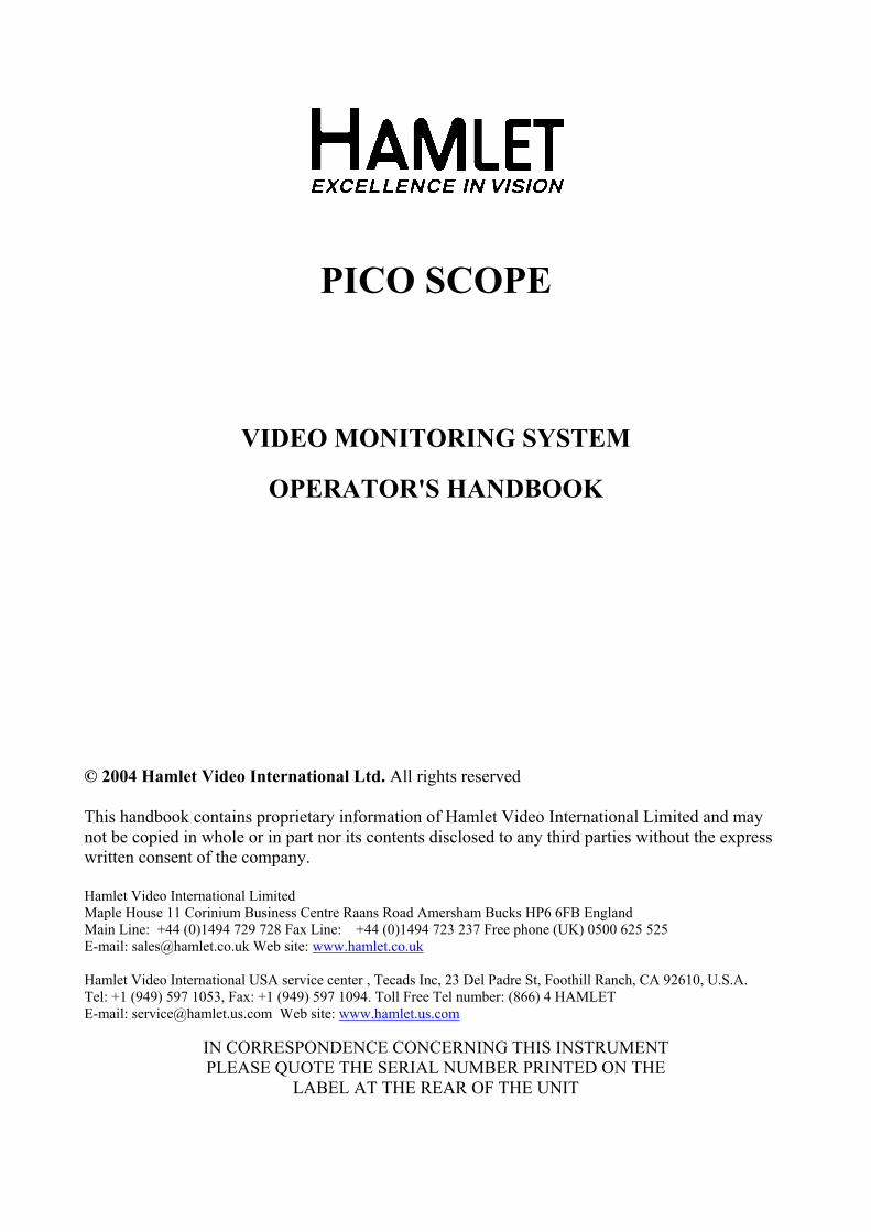
FRONT AND REAR PANELS
8
TECHNICAL SPECIFICATION DISPLAY AREA The waveforms are in boxes burnt into the video signal Small modes: Box is 128 lines high, with a width of 14uSec. Expand mode: Box is 512 lines high, with a width of 42uSec. SIGNAL CONNECTIONS Inputs: BNC connector with loop-through output. Return loss is better than 40db. Input impedance 15K ohm,max d.c.+/- 10 volts. Output: Output to monitor is 1 Volt to 75 ohms. Option: The Pico Scope can be factory set such that on power-down, the unit is bypassed so that the output is directly connected to the input, and the loop output is disconnected. SPECIFICATION Response: FLAT is +/- 1% from 25Hz to 5.5MHz, -5% at 10MHz LPASS is a low pass filter -1db at 1MHz, -40db at 3.58 / 4.4MHz CPASS is a band pass filter -3db at +/- 750KHz Sensitivity: Black level displays 0%, white level displays 100% Calibrator: Error in CAL position is less than 1% (0.007V). Calibration line variable over full signal range. D.C. Restorer: Attenuation of less than 30% to line hum signals Display level change less than 2% for 1 volt change in signal level. POWER INT: 2 x 1.5V AA cells, life approx 4 hours (Lithium) 1.5 hours (Alkaline) or 1 hour (Nicad). EXT: 8V-15V D.C. at 0.21 amp. Centre negative. ENVIRONMENT Indoor use, 5 to 45 deg.C. ambient to 2000m. Max humidity 80% to 31 deg.C decreasing to 50% at 40 deg.C. Overvoltage category 2. Pollution degree 1.
WEIGHT 450g or 500gr with batteries.
9
OPERATING INSTRUCTIONS OFF - ON - MIX Enables the power supply, provides a mix between the picture and waveform SCALE Controls the brightness of the internal electronic graticule TOP - BTM Gives small display at top of screen, full size display or small display at bottom of screen. (LEFT-RIGHT) An internal jumper selects left or right small displays. CPASS - FLAT - LPASS Switches the video filtering between flat, low pass and chroma pass modes. CURSOR Provides a variable electronic cursor for measurement comparisons. CAL - OFF - VAR Gives a calibrated cursor position, cursor off or variable control. CHOICE OF POWER SOURCE If no external supply is present, the Pico Scope will operate from its internal batteries. To conserve battery life, it will only operate when input video is applied. The front panel LED will change from GREEN to RED when the batteries are nearly exhausted. The correct battery polarity is with the caps (positive) facing outwards. When a suitable external supply is present, this will automatically be used instead of the internal batteries.
10
ADJUSTMENTS AND CALIBRATION AMPLITUDE CALIBRATION Preset controls are provided on the analog board for fine adjustment of waveform gain and lift in relation to the electronic graticule. Adjust R5 for gain and R28 for lift. Adjust R4 for cursor cal at 100%. MIX LEVEL Adjust R13 (mix) for desired background level in mix mode FILTERS Adjust L1 for minimum residual chroma in LPASS mode. Adjust L2 for maximum chroma in CPASS mode. DIGITAL BOARD Using a meter with input resistance greater than 1M ohm: Adjust L1 with a plastic tool for 1.5 volts at R7
11
GENERAL DESCRIPTION
INTRODUCTION The Pico Scope is basically an oscilloscope, but with the CRT tube replaced by an analogue to digital converter circuit and a television field store, which act as a digital scan converter In order to obtain a display identical to that produced on an analogue CRT, the field store is addressed in the same way as the electron beam in a conventional instrument scans its phosphor
INPUT VIDEO The incoming video signal is buffered and DC restored, then split in two ways. One path is via the output waveform inserter and out to the t.v. display monitor. The second path is to the oscilloscope section, which contains the usual filters, gain controls and sync separators. The resultant video signal is then digitised to provide the Y axis data for the video memory.
DIGITAL STAGES Video memory X axis data is obtained from a line locked counter. The memory is read-out from in synchronism with the input video signal to produce the required output display areas, with their size and position being selectable.
GRATICULE The internally generated electronic graticules are stored in the master gate array, which allows custom designs to be implemented. They are superimposed on to the output video in synchronism with the field store to give exact calibration with no parallax errors The Pico Scope is split into two circuit boards, Analog and Digital.
12
ANALOG BOARD VIDEO IN/OUT The input video is amplified at U2B and DC restored using feedback restoration at U5A. Video is then fed to switcher U3 which gates in the waveform display on black or variable background video for mix, and is output via video buffer U2A. The waveform information is formed at T1 and T8 by adding the field store and scale signals. SYNC SEPERATOR U4 provides sync separation for clamp pulse use and for output to the digital board. CURSOR During field blanking, U3 switches the ADC input to a DC level from the cursor control or cal preset. VIDEO PATH The video signal is fed via the gain preset and filters and goes to the digital converter U1. A to D CONVERTION The ADC is fed with a 10 MHz timing clock from the digital board which governs the sample point and output latch clocking.
13
DIGITAL BOARD This board is the digital scan converter, comprising clock and control signal generators for the analogue board and memory, two field memories and graticule generator. It is split into read and write sections. All the logic is implemented in a single gate array. READ ADDRESS Syncs from the analogue board are digitally separated to produce horizontal and vertical trigger pulses. The horizontal pulses lock the 18.5MHz clock oscillator, which clocks the horiz read timing counter. Similarly, vertical sync phases up the vertical timing counter. These two counters determine the output display sizes and positions for full screen displays, small screen top and small screen bottom displays. The 25Hz EVEN signal enables the memories to changeover between reading and writing in synchronism with the input video. WRITE ADDRESS Horizontal pulses are used to phase-up the write counter to incoming video. The 18.5MHz clock is divided by two to produce the clock for the ADC and the memory write enable. This clock is then divided by two again for the timebase clock. The two 64Kx4 fast static rams are the two fields of memory for the scan converter. During television field one, the first memory is written into and the second is read out from. During television field two the action is reversed, allowing totally separate reading and writing, and doubling memory speed. ADDRESSING Memory A0 to A7 is the horizontal address, with A0 held low in the small display mode and being the least significant bit in expand mode. Memory A8-A15 is the vertical address, with A8 the least significant bit in full screen mode, but not used in normal mode (held low). WRITING The memory is written into in a read-modify-write manner, so that at each write address, previous memory data is read out, incremented by one and written back in. This gives true 4 bit (15 level) brightness output. OUTPUT The memory outputs are latched and fed to a four bit DAC to provide the waveform brightness information to feed back to the analogue board, where it is inserted into the output video signal. ERASURE Erasure is carried out by writing a logic 0 into each memory address during its readout frame. Each bit is erased straight after it has been read out. GRATICULE The graticules are generated in the gate array and output to the analog board.
2 x Knobs, lined - SIFAM S111125B 2 x Knob Caps, lined, blue - SIFAM C111 (+colour) 3 x BNC r/a pcb sockets 1 x 12V Power connector - FARNELL 224-972 2 x Insulating Sheets, 135mm x 80mm 1 x Battery Holder, Bulgin 2 x AA in-line
19
ANALOG BASICS COMPONENT COLOUR The colour picture can be distributed in two forms, whether in 625 or 525 line standards: RGB This is the basic signal produced by a camera etc and fed to a colour c.r.t. It consists of three primary signals, Red, Green and Blue. By convention, black level is at 0mV and peak brightness is at + 700mV. YCrCb As the human eye can see less resolution with colours, the video can be modified to take advantage of this to reduce the amount of information needed. The picture is separated into monochrome and colour components. The monochrome Y signal is formed from: Y = (0.3 x Red) + (0.59 x Green) + (0.11 x Blue) approximately. This signal has black level at 0mV and maximum white level at + 700mV. The colour components are two colour difference signals: Cr = (R-Y) and Cb = (B-Y) These are weighted to give maximum values of +/- 350mV and are bandwidth restricted to half that of the Y component. PAL Fig 3 shows an encoded 100% colour bar signal. The two colour components of Cr and Cb are used to amplitude modulate a 4.43361875Mhz carrier signal. The two carriers are arranged to be 90 degrees apart before they are combined with the Y luminance signal, so that they can be decoded separately. The PAL system is designed to minimise hue errors by phase reversing the Cr axis on alternate lines (Phase Alternate Line). This reversal is copied by the decoder, so that the hue error will now alternate in phase. By combining the chrominance from two adjacent lines, the error is thus cancelled out. NTSC Fig 4 shows an encoded SMPTE (75%) colour bar signal. The two colour components of Cr and Cb are used to amplitude modulate a 3.579545Mhz carrier signal, but they are first modified into I and Q signals to reduce the overall maximum chrominance level when combined.
20
Fig 3.
21
Fig 4.
22
SC-H RELATIONSHIP PAL appears, at first sight, to be a four field system: field 1 being identical to field 5, and field 3 having the opposite pal switch phase. However, if a switch or edit is made between two video sources which are in the same pal sequence only, a small horizontal picture shift will often be noticed, this is due to the relationship between subcarrier and line frequencies. In order to avoid chroma patterning on monochrome receivers the PAL subcarrier frequency was chosen to have a 90 degree offset per television line, with 25Hz added on so that any remaining patterning would run through the picture: F (pal) = (283.75 x 15.625KHz) + 25Hz = 4.43361875MHz The drawback of this is that after one PAL frame of four fields the subcarrier will have executed exactly 354689.50 cycles, so it will be 180 degrees shifted from its original phase at the same sync point. Hence the subcarrier to horizontal sync (SC-H) phase will only repeat every EIGHT fields. A similar problem also exists in NTSC, except that it is a four field system rather than eight field. F (ntsc) = (227.5 x 15.73426373KHz) = 3.579545MHz After one NTSC frame of two fields, the subcarrier will have executed exactly 119437.50 cycles, so it will then be exactly 180 degrees shifted from its original phase at the same sync point hence the sc-h phase will only repeat every FOUR fields. If a video edit or switch is made without regard to the above field sequence, there is a 50/50 chance of picking the wrong eight field match. This will cause an SC-H phase jump producing a picture shift of half a cycle of subcarrier. Whilst this may be acceptable if cutting to a different shot, in animation or tag-editing the shift would be very noticeable. To produce reliable match frame edits it is therefore necessary to identify the correct field sequence. In addition, if due to misalignment, the SC-H phase was displaced from the ideal by 90 degrees, the field relationship would be uncertain. Both these problems can be addressed by having an instrument which displays the subcarrier phase to horizontal sync phasing. Zero SC-H phase has been defined as a positive zero-crossing of subcarrier at the vertical sync point on field 1. Systems can now be adjusted in the exactly correct SC-H phase to avoid uncertainty when near to the 90 degree point. A video signal in the exactly wrong eight-field sequence would show up as an 180 degree SC-H phase error.
23
USEFUL WEBSITES HAMLET www.hamlet.co.uk HAMLET (USA) www.hamlet.us.com SMPTE www.smpte.org Society of Motion Picture Television
Engineers DIN www.din.de German Standards Institute EBU www.ebu.ch European Broadcasting Union AES www.aes.org Audio Engineering Society ITU www.itu.int International Telecommunication Union
CONTACT DETAILS AND CUSTOMER SUPPORT For any form of assistance in maintaining your Pico Scope, please contact: Hamlet Video International Limited Maple House 11 Corinium Business Centre Raans Road Amersham Bucks HP6 6FB England Main Line: +44 (0)1494 729 728 Fax Line: +44 (0)1494 723 237 Free phone (UK) 0500 625 525 E-mail: [email protected] Web site: www.hamlet.co.uk Hamlet Video International USA service center , Tecads Inc, 23 Del Padre St, Foothill Ranch, CA 92610, U.S.A. Tel: +1 (949) 597 1053, Fax: +1 (949) 597 1094. Toll Free Tel number: (866) 4 HAMLET E-mail: [email protected] Web site: www.hamlet.us.com In correspondence concerning this instrument, please quote the serial number, which you will find